1
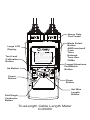
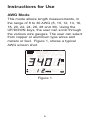
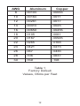
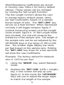
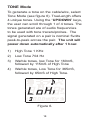
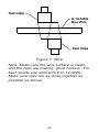
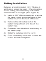
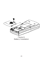
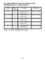
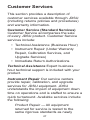
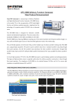
TrueLengthf Cable Length Meter
User's Guide
www.jdsu.com/know
Heavy Duty
Test Leads
Large LCD
Display
Test Lead
Calibration
Button
Up Button
Power
Button
Pair/Single
Conductor
Button
Mode Select
Button
AWG/mm/mm2
Coax
Telco
Network
Tone Gen.
OHMs
Copper/Aluminum
Feet/Metric
Button
Down
Button
Set Wire
Length
Button
TrueLength Cable Length Meter
CLM400
! Warning
Do not attach test leads to energized cables.
The TrueLength unit may be damaged.
Description
The TrueLength cable length meter is an
easy-to-use, versatile compact handheld unit
for measuring cable length and generating
tone. TrueLength works on virtually any
single or two conductor cables for testing
and troubleshooting.
Key Features
• Measure distance to open or distance to
short
• Modes of operation: AWG/mm/mm2,
Telco, Network, Coax, Tone Generator and
Ohms
• Single or dual (pair) conductor length
measurements in feet or meters
• Audible indicator for shorted wires
• Large LCD, easy-to-read under sunlight
• Measures wires 8 to 30 AWG (3.264mm
/8.366 mm² to 0.255mm/0.051 mm²)
• Copper (CU) or Aluminum (AL) wire
measurements
• 120vac Voltage Protection
• 12 pre-set wire gauge settings
• 12 user programmable wire gauge settings
• 4 selectable tones
• Requires 9 volt battery (not included)
• Auto shut down
• Resistance 0 to 635 Ohms
• Opens/Capacitance 0 to .082uf (approx.
5K feet)
• Measurements at milliohm resolution
• CE certified
General Functions
PWR Key and Auto Power Off
Turn the unit on and off. TrueLength
powers off automatically after 10 minutes,
if no keys have been depressed. The timer
is reset every time a key depression has
been detected. In Tone Mode unit will
automatically power down after 1 hour.
MODE Key
TrueLength provides eight modes of
operation, depressing the “MODE” key will
cycle through the various modes:
• AWG/mm/mm2 - Measures Cable
Length in AWG/mm/mm2, feet/meters,
Copper/Aluminum
• COAX - Measures cable length,
distance to opens or distance to short
• TELCO - Measures cable length,
distance to opens or distance to short
• NETWORK - Measures cable length,
distance to opens or distance to short
• OHMS - Measures 0 to 635 ohms
• TONE - Generates 4 different unique
tones
Al/CU UNITS Key
Key has a dual function.
Function 1: The user can select wire
alloy type copper (CU) or aluminum
(AL) by pressing the “AL/CU/UNITS”
key (toggle) normally. The “AL” or “CU”
icon will illuminate in the lower right
corner of the display as selected.
Function 2: Holding the “AL/CU/
UNITS” key down approximately 1.5
seconds, the unit will toggle between
units of measure “Feet” or “Meters”.
The “M” or “FT”, icon will illuminate in
the center right hand side of the screen
as selected.
LCD Display Icons
Feature
Description
Coax Mode
Telco Mode
Network Mode
Tone Mode
Dual Conductor icon (AWG/mm/mm2
Mode)
Single Conductor icon (AWG/mm/mm2
Mode)
Short Symbol, indicates the presence
of a short between two conductors. An
Audible Tone will also be generated.
(Coax, Telco, and Network Mode)
Indicate unit has detected the presence
of voltage on the line.
Battery Low Icon. TrueLength monitors
battery status continuously when it is
powered on. When the battery low icon
is activated, the unit has approximately
15 minutes of battery life. The battery
should be replaced as soon as possible.
Cable testing results will become
unreliable if the 15 minute period is
exceeded
Instructions for Use
AWG Mode
This mode allows length measurements, in
the range of 8 to 30 AWG (8, 10, 12, 14, 16,
18, 20, 22, 24, 26, 28 and 30). Using the
UP/DOWN keys, the user can scroll through
the various wire gauges. The user can select
from copper or aluminum type wires and
meters or feet. Figure 1, shows a typical
AWG screen shot.
Figure 1
AWG/mm/mm2 cross Reference table
A.W.G.
Diameter
(mm)
Area (mm²)
#8
3.264
8.37
#9
2.906
6.63
#10
2.588
5.26
#11
2.305
4.17
#12
2.053
3.31
#13
1.828
2.62
#14
1.628
2.08
#15
1.450
1.65
#16
1.291
1.31
#17
1.150
1.04
#18
1.024
0.823
#19
0.912
0.653
#20
0.812
0.518
#21
0.723
0.410
#22
0.644
0.326
#23
0.573
0.258
#24
0.511
0.205
#25
0.455
0.162
#26
0.405
0.129
#27
0.361
0.102
#28
0.321
0.081
#29
0.286
0.064
#30
0.255
0.051
PAIR SGL Key
TrueLength can measure single or
dual conductor wires. Depressing the
“PAIR SGL” key toggles between single
or dual conductor. Single conductor
measurements assume the unit is connected
at both ends of the wire/conductor. In
AWG/mm/mm2 mode dual conductor
measurements assume the user is
measuring at one end of the wire, while the
other end of the pair is shorted (wire length
= total resistance / 2).
SET LEN Key (AWG Mode example)
The Set Length function allows the user to
change factory default values, ohms per feet
coefficients, based on a sample length of
wire. The “SET LEN” key serves as a dual
function when depressed normally, it will
toggle between AWG mode screen (figure 1)
and Set Length mode screen (figure 2). In
Set Length mode, the unit will measure the
resistance of the sample wire. The length of
wire can be set by adjusting the “UP/DOWN”
keys in the range of 100 to 200 feet. The
smaller digits display ohms per feet, based
on the sample wire. Holding the “SET LEN”
key down for a few seconds will store the
new coefficients overriding factory default
values.
Example: The factory default for 12 AWG
Copper is .0017 Ω per feet.
)
Using the “MODE” key, select AWG
mode and set the AWG to 12 using the
“UP/DWN” keys.
Depress the “SET LEN” (LEN = Length) key,
a new screen will pop up (see Figure 2). In
this mode the “UP/DOWN” keys are used to
adjust the larger digits to match the length
of the sample wire (100 – 200 ft range).
Assume the sample wire is 150 feet and
its resistance is equal to .315 ohms. The
smaller digits on the left hand side of the
screen will display “002.1mΩ” (Ω per feet).
)
To store the new value, depress the
“SET LEN” key down approximately
1.5 seconds, a confirmation beep will
be generated. The new 12AWG length
coefficient of .0021Ω per feet will be
stored in memory in place of the factory
default of .0017 Ω per feet.
10
Figure 2
Note: Restoring Factory Default Values.
To restore factory coefficients back to its
original values, hold the “UP/DOWN keys
and the Power” key down at the same time
when powering down the unit. Any previous
values stored by the user will be deleted
from memory.
11
AWG
Aluminum
Copper
8
.00103
.00063
10
.00164
.0011
12
.00261
.0017
14
.00414
.0025
16
.00659
.00455
18
.0105
.0061
20
.0167
.00945
22
.0265
.0168
24
.0421
.0273
26
.067
.0436
28
.106
.0637
30
.169
.108
Table 1
Factory Default
Values, Ohms per Feet
12
COAX, NETWORK, TELCO Mode
Coax (See Figure 5 for coax F connection
measurements), Network and Telco modes
detect distance to opens and distance to
shorts. Figure 3, shows a Network screen
shot (line open).
Figure 3
TrueLength determines length by measuring
line capacitance when the line is open
or measuring resistance when the line is
shorted. Measuring opens, the user can
adjust the capacitance coefficient (10 to
40pf per feet) to calculate the cable length
by using the “UP/DOWN” keys. TrueLength
supports three user-adjustable length
coefficients, one for each type of cable
(Coax, Network and Telco). TrueLength
stores these coefficients in memory even
when the unit is powered off.
13
Short/Resistance coefficients are stored
in memory (see Table 2 for factory default
values). These values can be changed
by running the Set Length Function.
The Set Length function allows the user
to change factory default values, ohms
per feet coefficients, based on a sample
known length of wire. The “SET LEN” key
serves as a dual function. When depressed
normally it will toggle between figure 3
(normal measuring screen) and Set Length
mode screen, figure 4. In Set Length mode
(line shorted), the unit will measure the
resistance of the sample wire. The length of
the sample wire can be set adjusted by the
UP/DOWN keys in the range of 100 to 200
feet. The smaller digits display the ohms
per feet based on the sample wire. Holding
the “SET LEN” key down for a few seconds
will store the new coefficients.
Example: The factory default for Network
wire is .0273 Ω per feet.
)
Using the “MODE” key, select Network
mode.
)
Depress the “SET LEN” (LEN = Length)
key, a new screen will pop up (see
figure 4). In this mode the “UP/DOWN”
keys are use to adjust the larger digits
to match the length of the sample
14
wire (100 – 200 ft range). Assume
the sample wire is 150 feet and its
resistance is equal to .315 ohms. The
smaller digits on the left hand side of
the screen will display “002.1mΩ”.
3)
To store the new value, depress the
“SET LEN” key down approximately 1.5
seconds, a confirmation beep will be
generated. The new Network length
coefficient of .0021Ω per feet will be
store in memory.
Figure 4
Note: Restoring Factory Default Values To
restore ohms per feet factory coefficients
back to its original values, hold the Power
and UP/DOWN keys down at the same
time when powering down the unit. Any
previously stored values by the user will be
overwritten to factory default.
15
In order to obtain symmetrical
test results for Shorts and Opens
measurements the TrueLength must
have the correct “capacitance per feet
coefficient” and “resistance per feet
coefficient” of the wire under test.
Changing Opens/Capacitance Coefficient
using Set Length.
Changing capacitance coefficients can also
be accomplished by following the steps
above (Cable/wire must be open) based on
the sample wire (100 to 200 ft). TrueLength
measures the total capacitance of the cable
and displays the value in the lower left hand
corner of the LCD (cable must be within 10
to 40pf per feet range, otherwise meter will
indicate OL).
Mode
Capacitance
Opens
Ω per feet / AWG
shorts
Coax
22.0pf
.0663 Ω/ NA
Network
15.0pf
.0273 Ω / 24 AWG
Telco
17.5pf
.0273 Ω / 24 AWG
Table 2
Factory Default Values
16
Figure 5.
BNC to F connection for Coax
measurements.
17
TONE Mode
To generate a tone on the cable/wire, select
Tone Mode (see figure 6). TrueLength offers
4 unique tones. Using the “UP/DOWN” keys,
the user can scroll through 1 of 4 tones. The
tones generated are of audio frequencies
to be used with tone tracers/probes. The
signal generated on a pair is nominal 5volts
peak-to-peak across the pair. The unit will
power down automatically after 1 hour.
)
High Tone 1 KHz
)
Low Tone 704 Hz
3)
Warble tones, low Tone for 160mS,
followed by 115mS of High Tone
4)
Warble tones, Low Tone for 365mS,
followed by 65mS of High Tone.
Figure 6.
18
TEST LEAD CALIBRATION
)
Hold down the “LEAD CAL” key until
the units displays “CAL”. The unit will
display “CAL” for a few seconds then
display “Shrt LEAd”.
)
Proceed to short the leads as illustrated
in figure 7. Once connected properly
to the bus wire, the user must depress
the “LEAD CAL” key again. Upon
competition, the unit will beep and
display “OPEN LEAd”.
3)
Disconnect the leads from the short.
With the test leads open press the
“LEAD CAL” button. Upon competition,
the unit will be beep and go into
its normal mode of operation. This
completes the calibration procedure.
This procedure must be done correctly
to ensure good measuring results.
19
Test Clips
8-14 AWG
Bus Wire
Test Clips
Figure 7. Wire
Note: Make sure the wire surface is clean
and the clips are making good contact. For
best results use solid wire 8 to 14 AWG.
Make sure clips are as close together as
possible as shown.
20
Models, options & accessories
Item
Ordering number
TrueLength cable length
meter
CLM400
Replacement double
banana to BNC + BNC to
F jack
TP75
Replacement cordset and
clips for CLM400
TP76
Pouch for CLM400
PC500
21
Battery Installation
Batteries are not included. Only Alkaline 9
volt battery should be used. When installing
a new battery, disconnect any test cables
connected to TrueLength. (See Figure 8)
)
Using a #2 Phillips screwdriver, unscrew
the battery door screw and remove the
battery cover on the back of the unit.
)
Remove the old battery out of the
battery compartment and detach the
battery cap.
3)
Connect a new Alkaline 9 volt battery to
the battery cap.
4)
Slide the batteries into the cavity.
5)
Close the battery cover and replace the
screw. Do not overtighten.
22
Figure 8.
Battery Installation
23
Specifications
Physical Dimensions
Size
3.3 x 7.6 x 15.2 cm
1.3 x 3.0 x 6.0 inches
Weight
326 grams (11.5 oz.)
Includes battery and test leads
Environmental
Operating temperature:
0 to 50 deg C (32 to 122 deg F)
Storage temperature:
-10 to 60 deg C (14 to 140 deg F)
Humidity:
10% to 90%, non-condensing
Battery Life
Battery life is based on a typical 9V alkaline
battery
Standby: 2.5 years
Cable Testing: 20 hours into 60 Ohm
load (Note: Smaller
resistance loads will
result in shorter battery
life)
24
Cable Types
Singel or Dual conductor, AWG 8 - 30, mm
3.264 - .255, mm2 8.37 - .051, Netwwork
cabling, coax and telco.
High Voltage Protection
120vac max.
Length Measurement Range Opens/
Capacitance: Max .082uF
Wire
Type
Typical
Capacitance
per Feet
Length
Tolerance
Telecom
17.5pf
0 - 1371 meters
0 - 4500 feet
Min. Cable
Length
0.91 meter
(3 feet)
±2%, +3
digits LSD
Network
Wire
15.0pf
0 - 1524 meters
0 - 5000 feet
Min. Cable
Length
0.91 meter
(3 feet)
±2%, +3
digits LSD
Coax
22.0pf
0 - 1066 meters
0 - 3500 feet
Min. Cable
Length
0.91 meter
(3 feet)
±2%, +3
digits LSD
25
Length Measurement Range DC
Resistance 0 - 635 ohms
AWG
8, 10
12, 14, 16
18, 20, 22
24, 26, 28
30
Min.
Feet
Length
Tolerance
5.0
0 - 3047 meters
0 - 9999 feet
±2%, ±3 LSD
4.0
0 - 3047 meters
0 - 9999 feet
±2%, ±3 LSD
3.0
0 - 3047 meters
0 - 9999 feet
±2%, ±3LSD
1.0
0 - 3047 meters
0 - 9999 feet
±2%, ±3 LSD
1.0
0 - 1792 meters
0 - 5879 feet
±2%, ±3 LSD
LSD = Least Significant Digit.
26
Customer Services
This section provides a description of
customer services available through JDSU
(including returns policies and procedures)
and warranty information.
Customer Service (Standard Services)
Customer Service accompanies the sale
of every JDSU product. Customer Service
services include:
• Technical Assistance (Business Hour)
• Instrument Repair (Under Warranty
Repair, Calibration Services, and
Upgrade Services)
• Immediate Return Authorizations
Technical Assistance Expert business
hour technical support is included with your
product.
Instrument Repair Our service centers
provide repair, calibration, and upgrade
services for JDSU equipment. JDSU
understands the impact of equipment down
time on operations and is staffed to ensure a
quick turnaround. Available services include
the following:
Product Repair — All equipment
returned for service is tested to the
same rigorous standards as newly
27
manufactured equipment. This
ensures products meet all published
specifications, including any applicable
product updates.
Calibration — JDSU’s calibration
methods are ISO approved and based
on national standards.
Factory Upgrades — Any unit returned
for a hardware feature enhancement will
also receive applicable product updates
and will be thoroughly tested, ensuring
peak performance of the complete
feature set.
Equipment Return Instructions Please
contact your regional Technical Assistance
Center to get a Return or Reference
Authorization to accompany your equipment.
For each piece of equipment returned for
repair, attach a tag that includes the following
information:
•
•
•
•
Owner’s name, address, and
telephone number.
The serial number (if applicable),
product type, and model.
Warranty status. (If you are unsure
of the warranty status of your
instrument, contact Technical
Assistance.)
A detailed description of the
28
problem or service requested.
The name and telephone number
of the person to contact regarding
questions about the repair.
•
The return authorization (RA)
number (US customers), or
reference number (European
Customers).
If possible, return the equipment using the
original shipping container and material.
If the original container is not available,
the unit should be carefully packed so
that it will not be damaged in transit; when
needed, appropriate packing materials can
be obtained by contacting JDSU Technical
Assistance. JDSU is not liable for any
damage that may occur during shipping. The
customer should clearly mark the JDSUissued RA or reference number on the
outside of the package and ship it prepaid
and insured to JDSU.
•
29
Warranty Information
JDSU guarantees that its products will
be free of all defects in material and
workmanship. This warranty extends for the
period of 12 months for test instruments
and 3 months for cables from date of
manufacture or purchase (proof of purchase
required).
All product deemed defective under this
warranty will be repaired or replaced at
JDSU’s discretion. No further warranties
either implied or expressed will apply, nor
will responsibility for operation of this device
be assumed by JDSU.
WEEE Directive Compliance
JDSU has established processes in
compliance with the Waste Electrical and
Electronic Equipment (WEEE) Directive,
2 002 /96/EC. This product should not be
disposed of as unsorted municipal waste
and should be collected separately and
disposed of according to your national
regulations. In the European Union, all
equipment purchased from JDSU after
005 -08 -13 can be returned for disposal
at the end of its useful life. JDSU will
ensure that all waste equipment returned
30
is reused, recycled, or disposed of in an
environmentally friendly manner, and in
compliance with all applicable national
and international waste legislation. It is
the responsibility of the equipment owner
to return the equipment to JDSU for
appropriate disposal. If the equipment
was imported by a reseller whose name
or logo is marked on the equipment, then
the owner should return the equipment
directly to the reseller. Instructions for
returning waste equipment to JDSU can
be found in the Environmental section of
JDSU’s web site at www.jdsu.com. If you
have questions concerning disposal of your
equipment, contact JDSU’s WEEE Program
Management team at WEEE.EMEA@jdsu.
com.
31
www.jdsu.com/know
Document Information
Doc. # TU9895
Revision 501, 09-08
English