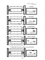
1
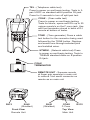
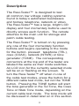
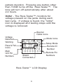
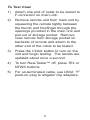
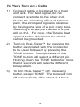
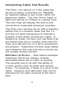
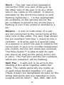
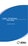
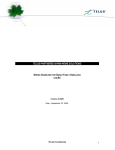
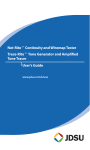
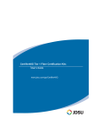
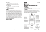
Resi-Testerf Whole-House Cable Tester
User's Guide
www.jdsu.com/know
TEL - (Telephone cable test)
Press to power on and begin testing. Tests to 3pair USOC on standard and 6-position RJ-jack.
Press for 2 seconds to turn off split pair test.
Resi-Tester
TEL
COAX
NTWK
TONE
COAX - (Coax cable test)
Press to power on and begin testing.
Tests for shorts, opens and ID’s up to 20
unique remote’s on the F-conn jack. Use
with test terminator stored in back of RJ
remote at bottom of tester.
TONE - (Tone generator) Press a cable
test button for the connector being used
followed by the TONE button. Displays
and sends tone through selected pins
and installed wires.
NTWRK - (Network cable test) Press
to power on and begin testing. Tests to
T568A/B standard cable on 8-position
RJ-jack.
COAX
TERMINATOR
REMOTE UNIT - Squeeze remote
at finger grip openings in main unit
to remove. Use same connector on
remote as on main unit.
RJ12
RJ45
(Shielded)
Front View
Remote Unit
RJ45
(Shielded)
COAX
F-Conn.
Top View
Main Unit
RJ12
WARNING!
Do not attach to AC power. The ResiTester™ may be damaged and cause a
safety hazard for the user.
CAUTION!
Improperly crimped, damaged or uncrimped plugs can damage the jacks on
the Resi-Tester™. Inspect plugs for proper
termination and crimping before inserting
into the tester. Contacts should always
be recessed into the plastic grooves of the
plug. Do not use 6-position plugs with the 8position (network) jack.
Features
• Tests network (8-wire), telephone (6wire) and coax cabling systems
• Supports 8 network remotes and 20
coax remotes (optional, see accessory
list)
• Large seven-segment LCD with icons
for clear results
• Cable test results displayed in wire map
format
• Tests for shorts, opens, miswires,
reversals and split pairs
• Displays PASS icon for correctly wired
T568A/B, both one-to-one & uplink
(cross-over) cables
• Displays PASS icon for correctly wired
6-pin telephone cables both straightthrough & reversed
• Tone generator mode for use with tone
tracers
• Auto-off in any mode and low power
consumption for long battery life
• Modular Plug Remote and Coax Test
Terminator store in the bottom end of
the case
Description
The Resi-Tester™ is designed to test
all common low voltage cabling systems
found in today’s automated businesses
and homes; telephone, network or video.
The Resi-Tester™ has a large, bright LCD
display and four momentary buttons used to
directly access each function. The remote
attaches to the main unit for storage and
patch cable testing.
The Resi-Tester™ is turned on by pressing
any one of the four momentary function
buttons and begins operating in the mode
for the button pressed: telephone (TEL),
coax (COAX), network (NTWK) or tone
generator (TONE). The corresponding
connectors at the top end of the tester are
labeled the same as their mode switches.
An LCD icon for the currently selected mode
will be on or flashing on the screen. To
turn the Resi-Tester™ off when in one of
the cable test modes, press the button for a
different cable test mode, but not the TONE
button. Pressing the TONE button will start
the tone generator in the Tel Tone, the Coax
Tone or Ntwk Tone mode, depending on the
current cable test mode. The tone mode will
be discussed in detail later on in this section.
Upon completion of a telephone or network
cable test, the wire map, ID and any faults
are displayed. The top line of numbers
on the display represents the connector
pins on the main unit. The second line
of pin numbers represents the connector
pin numbers of the remote, normally being
the same as the top line for a one-to-one
wired cable. If there is a miswire, the pin
numbers on the second line will indicate the
pin numbers detected and the “Fail” icon
will be on. The icon and the pins involved
in the error will flash. If no connection was
detected for some of the pins, the first and
second line of pin numbers will be blank in
those pin locations. If a short is detected,
the second line will have a ‘-’ in those
positions along with the “Short” icon being
on. If a split pair is detected, those pin
positions on the first and second line will be
flashing the pin numbers detected from the
remote and the “Split” icon will be flashing.
If there are multiple errors to display, there
will be a combination of the above error
displays. The ID icon will have a number
directly to the right of it, indicating the
remote ID number detected from the remote.
A new test is in progress whenever the “Tel”
or “Ntwk” icons are on.
In the coax mode, the “Open”, “Short” or
“Pass” icon will be on to indicate the results
of a test. If the cable passes, the “ID” icon
will be on as well as a remote ID number, on
the bottom line of the display. The “Coax”
icon turns on when a test is in progress.
As mentioned above, the tone generator
operates in Telephone, Coax and Network
modes. The different modes are provided
so that the pins or pairs being driven with a
tone signal are displayed in terms of one of
the three connectors. The specific mode is
selected by pressing one of the cable test
buttons (TEL, COAX or NTWK) followed by
the TONE button. If the Resi-Tester™ was
off when the TONE button is pressed, the
last cable test mode used will be selected.
The tone generator saves the driven pins
for each mode independently. For example,
selecting a different pin to drive in network
mode will not change the driven pin in coax
mode. Pressing any cable test mode button
will turn off the Resi-Tester™ when in tone
mode.
Telephone (TEL) Cable Test Mode - The
Resi-Tester™ assumes the 6-position jack
on the main unit and the remote will be used
for connecting the tester to the cable run to
be tested. This mode uses the 3-pair USOC
standard to define the pairs. Connector pins
1-6, 2-5 and 3-4 are the pairs defined by this
standard. The tester will display the “Pass”
icon when all 6 pins are correctly wired in a
one-to-one order. If all 6 pins are correctly
wired in the reverse order, the “Pass” icon
along with a flashing “Rev” icon will be
displayed. Standard telephone cables used
between a phone set and a wall jack are
usually reverse-pinned.
After turning on the telephone cable test
mode, subsequent presses of the TEL
button of less than 2 seconds long, forces
a new test cycle to begin immediately
upon release of the button. This is useful
to immediately begin a new test when
attaching a new cable to Resi-Tester™.
Holding the TEL button down for more than
2 seconds, turns the split pair test off. The
“Split” icon and the word “OFF” appearing
on the screen briefly indicate this. Another
long press will toggle back to the split pair
testing, and so on. When split pair testing
is not required, as in the testing of flat satin
cable, the split pairs can be turned off, so a
cable may pass based on continuity only.
Network (NTWK) Cable Test Mode - The
Resi-Tester™ assumes the 8-position jack
on the main unit and the remote will be used
for connecting the tester to the cable run to
be tested. The TIA/EIA 568A/B standard is
used to define the pairs. Connector pins
1-2, 3-6, 4-5 and 7-8 are the pairs defined
by this standard. The A and B standards
are the same except for color-coding and
are indistinguishable from each other by
electrical testing. The tester will display the
“Pass” icon when all 8 pins are correctly
wired in a one-to-one order. If all 8 pins are
correctly wired with the 1-2 and 3-6 pairs
crossed , the “Pass” icon will be displayed
along with a flashing “Uplink” icon. Uplink
cables are also known as crossover or
T568A-to-T568B cables and are commonly
used to connect two computers or two hub/
switches directly together.
After turning on the network cable test
mode, subsequent presses of the NTWK
button of less than 2 seconds, forces a new
test cycle to begin immediately upon release
of the button. This is useful to immediately
begin a new test when attaching a new
cable to the Resi-Tester™. Holding the
NTWK button down for more than 2
seconds, turns the split pair test off. The
“Split” icon and the word “OFF” appearing
on the screen briefly indicates this. Another
long press will toggle back to the split pair
testing, and so on. When split pair testing
is not required, as in the testing of flat satin
cable, the split pairs can be turned off, so a
cable may pass based on continuity only.
Tone - The tone mode generates audio
tones for use with tone tracers on all pairs,
a selected pair or a selected pin. The signal
generated on a pair has the signal on one
pin and the complement of the signal on
the other pin of the pair, yielding a nominal
10 volts peak-to-peak across the pair. The
pin number of the pin or the letters “P”( for
pin) and “S” (for shield) being driven with
tone and the currently selected tone pattern
are displayed on the screen along with the
“Tone” icon and the icon for the connector
assumed to be used. Once in the tone
generator mode, the TONE button steps to
the next connector pin(s) drive option for
presses of less than 2 seconds. When the
TONE button is pressed and held down
for longer than 2 seconds, the tone pattern
options are stepped through in turn until the
button is released. The tone pattern options
are Hi, Lo, HiLo1 and HiLo2. The HiLo
options are dual or warble tones of differing
pattern duration. Pressing any button other
than TONE turns off the Resi-Tester™. The
tone will turn off automatically after about
2.4 hours.
Volts! - The Resi-Tester™ monitors for
voltage present on the jacks during each
test cycle. If voltage is found, the “Volts!”
icon is displayed and testing stops until the
voltage is removed.
Special
Cable Icons
Voltage
Detected
Warning
Pass & Fail
Icons
Main
Unit Pin
Numbers
Tel Coax Ntwk Tone
Volts! Rev Uplink
Split Pass Fail
Open Short S ID 8
12345678
88888888
Shield
Connected
Mode Icons
Setup Mode
Remote ID
Number
Remote Pin
Numbers
Resi-Testerf LCD Display
Instructions for Use
Resi-Tester™ powers off automatically 9
minutes after the last button press in cable
testing modes and after 2.4 hours in tone
mode. Be sure to install a battery if using
for the first time, see battery installation
section.
Cable Testing
To Test a Patch Cable (see caution about
cables with bad plugs above)
)
Plug one end of patch cable into main
unit.
2)
Plug other end of cable into remote unit.
3)
Press TEL or NTWK as appropriate for
the jack the patch cable is connected
to. The Resi-Tester™ will turn on and
begin a test. If tester was already on,
press TEL or NTWK to initiate a new
test. Results are invalid if a cable is
attached during a test in progress.
)
To turn Resi-Tester™ off, press COAX
button.
10
To Test Coax
)
Attach one end of cable to be tested to
F-connector on main unit.
2)
Remove remote unit from main unit by
squeezing the remote lightly between
the thumb and forefinger through the
openings provided in the main unit and
pull out of storage pocket. Remove
coax remote from storage pocket on
backside of remote and attach to the
other end of the cable to be tested.
3)
Press the COAX button to turn on the
unit and begin testing. The results are
updated about once a second.
)
To turn Resi-Tester™ off, press TEL or
NTWK buttons.
5)
For un-terminated cable, use LB32; “F”
push-on plug to alligator clip adapters.
11
To Place Tone on a Cable
)
Connect cable to be traced to a main
unit jack. For best signal, do not
connect a remote to the other end.
Due to the shielding effect of twisted
pairs, the strongest signal is obtained
by having one wire of a pair carry tone.
Selecting a single pin instead of a pair
will do this. For coax, the Tone is best
applied to the shield and the shield
cannot be grounded.
2)
Turn on Resi-Tester™ by pressing the
button associated with the connector
to be used followed by pressing the
TONE button. Short presses of the
TONE button will select a different pin.
Holding down the TONE button for more
than 2 seconds will select a different
tone pattern.
3)
To turn Resi-Tester™ off, press any
button except TONE. The tone will turn
off automatically after about 2.4 hours.
12
Interpreting Cable Test Results
The Pass icon will be on if the cable has
all pins properly connected per T568A/B
for network cables or per 3-pair USOC for
telephone cables. The Fail, Short, Open or
Split icon will be on if there is a wiring error.
The wire map will display the end-to-end
connections measured whenever possible.
The Pass icon will also be on with a flashing
Uplink icon if a network cable has the 1-2
and the 3-6 pairs transposed to indicate a
properly wired uplink (crossover) cable. In
Telephone mode, the Rev icon will flash if all
connected pins are in reverse order and the
Pass icon will also be on if all 6 connections
are present. Telephone modular plug cables
used between the wall jack and a phone set
are usually reverse pinned.
Definition of Errors - (See failure example
drawings) The three classes of faults
discussed below are in order of severity.
The severity has to do with the ability of
a more severe error to mask less severe
errors. For example, if there is a short in the
cable, miswires and split pairs may not be
detected for the pairs involved in the short
fault.
13
Short - The pair has a low resistance
connection from one wire of the pair to
the other wire of the pair or to any other
wire in the cable or the shield. A short is
indicated by the Short icon being on and
flashing hyphenes ( - ) in the appropriate
pin positions on the second line for the
pin numbers involved in the shorts plus a
flashing S icon if the shield is shorted to a
pin.
Miswire - A wire or both wires of a pair
are not connected to the correct pins at the
other end of the cable. The wire map shows
the pin numbers from line 1 (main) to line 2
(remote). A reverse pair is a special case
of a miswire in which the pair is wired to the
correct pair of pins or to another designated
pair of pins, but the two leads are reversed.
The Resi-Tester™ is able to test for split
pair errors as long as the wiring errors are
in pairs. The Fail icon and the pin numbers,
which are miswired, will be flashing.
Split Pair - A split pair is an error in the
twisting of the wires together within the
cable. The cables generally are made up
of eight wires twisted together in 4 pairs.
These 4 pairs are designated as pairs by the
wiring standards and are intended to carry
a signal and its return. 1&2, 3&6, 4&5 and
14
7&8 are the pairs designated by T568A/B for
a RJ45 jack or plug. A cable can be wired
with correct continuity but not with correct
pairing. This most often happens when
the cable is terminated consistently at both
ends, but in the wrong order. A dynamic
or AC test is required to detect this type of
error. If the only error is a split pair error, the
cable has correct continuity. If cross talk
is not a concern, as in flat satin cable, the
cable is good if the only error is the split pair
error. The Split icon and the pin numbers
on the first and second line of the wire map
with split pairs flash when there is a split pair
error.
Resi-Tester™ has the ability to turn off the
split pair error testing. Pressing the button
for the current cable test mode for more than
2 seconds turns off the split pair testing. The
“Split” icon and the word “OFF” appears on
the screen briefly to indicate this. The split
pair testing will resume the next time the
tester is turned on, or may be toggled back
on by another 2 second press of the current
test mode button.
15
DARK = ON
LIGHT =FLASHING
1
2
3
4
5
6
7
8
1
2
3
4
5
6
7
8
1
2
3
4
5
6
7
8
1
2
3
4
5
6
7
8
1
2
3
4
5
6
7
8
1
2
3
4
5
6
7
8
1
2
3
4
5
6
7
8
1
2
3
4
5
6
7
8
OPEN
Ntwk
Open
S ID
2
12345678
345678
SHORT
Ntwk
Short
S ID
2
1 2 3 4 5 67 8
123456- -
MISWIRE
Ntwk
Fail
S ID
2
12 3 4 5 6 7 8
13 2 4 5 6 7 8
SPLIT PAIR
Ntwk
Split
S ID
2
12345678
1 2 34 5 6 7 8
(1 not twisted with 2; 3 not twisted with 6)
T568A/B Passing Cable (unshielded)
1
2
3
4
5
6
7
8
1
2
3
4
5
6
7
8
16
Ntwk
Pass
ID
2
12345678
12345678
Battery Replacement
When the battery low icon is on, the battery
should be replaced as soon as practical.
The cable testing results will become
unreliable when the battery reaches about
4.5 volts. To replace battery:
)
Remove the screw from the battery door
on the back of the unit with a #1 Philipshead screwdriver.
2)
Pull battery out of cavity and remove
battery snap.
3)
Connect a new Alkaline 9 volt battery to
battery snaps. Place battery back into
body with battery snaps placed toward
front end of compartment.
)
Replace battery door and screw being
careful to not over tighten the screw.
17
Specifications
Physical Dimensions:
Size: 13.2 x 7.3 x 4.1 cm
(5.2 x 2.9 x 1.6 inches)
Weight: 242 grams (8.5 oz.) with battery and remote
Environmental:
Operating temperature: 0 to 50 °C
(32 to 122 °F)
Storage temperature: -10 to 60 °C
(14 to 140 °F)
Humidity: 10% to 90%, non-condensing
Battery Life (9V Alkaline battery, typical) times
are for the full capacity of the battery used continuously in one of the following modes Standby: 2.5 years
Cable Testing: 150 hours
Tone Generator: 250 hours
Cable Types: Shielded or unshielded, CAT-6,
CAT-5E, CAT-5, CAT-4, CAT-3 and Coax
Minimum cable length for testing of split
pairs: 1 meter (3 feet)
Coax Cable: 100 ohms maximum DC
resistance, center conductor plus shield
18
Accessories
LB32 - 24”, F push-on plug to alligator clip
set (to use with TP315)
TP20 - 7.5” cable assembly with no-fault 6
position plugs, reverse-pinned. Use to map
and test 2, 4 or 6 pin telephone wiring. Can
be used with RJ45 (8-position) jacks and will
not damage pins or connector.
TP40 - 12” Cable assembly, RJ45 to alligator
clips
TP62 - Adapter, F-conn plug to BNC jack.
Use to convert main unit F-conn jack to BNC
jack
TP63 - Adapter, F-conn jack to BNC jack.
Use to convert Coax test terminators to BNC
jack.
TP310 - Set of 10 numbered F-conn test
terminators
TP311 - Set of 20 coax remote identifiers for
Resi-Tester™ and Testifier™
TP312 - Set of 20 RJ45 wiremappers for
Resi-Tester™ and Testifier™
TP314 - Set of 20 RJ11 wiremappers for
Resi-Tester™ and Testifier™
19
TP315 - Set of 20 Speaker Seeker™ alligator clip remote identifiers for Resi-Tester™
and Testifier™
TP608 - Set of 7 numbered remotes for
LanScaper™, LanRoverPRO™, Resi-Tester™ or Testifier™
KP410 - Security & Alarm System adapter kit
includes (9) RJ45 to alligator clip lead sets
and an LB66 in a zippered pouch. Use with
TP608 to map and test individual twisted pair
runs.
20
Customer Services
This section provides a description of
customer services available through JDSU
(including returns policies and procedures)
and warranty information.
Customer Service (Standard Services)
Customer Service accompanies the sale
of every JDSU product. Customer Service
services include:
• Technical Assistance (Business Hour)
• Instrument Repair (Under Warranty
Repair, Calibration Services, and
Upgrade Services)
• Immediate Return Authorizations
Technical Assistance Expert business
hour technical support is included with your
product.
Instrument Repair Our service centers
provide repair, calibration, and upgrade
services for JDSU equipment. JDSU
understands the impact of equipment down
time on operations and is staffed to ensure a
quick turnaround. Available services include
the following:
Product Repair — All equipment
returned for service is tested to the
same rigorous standards as newly
21
manufactured equipment. This
ensures products meet all published
specifications, including any applicable
product updates.
Calibration — JDSU’s calibration
methods are ISO approved and based
on national standards.
Factory Upgrades — Any unit returned
for a hardware feature enhancement will
also receive applicable product updates
and will be thoroughly tested, ensuring
peak performance of the complete
feature set.
Equipment Return Instructions Please
contact your regional Technical Assistance
Center to get a Return or Reference
Authorization to accompany your equipment.
For each piece of equipment returned for
repair, attach a tag that includes the following
information:
•
•
•
•
Owner’s name, address, and
telephone number.
The serial number (if applicable),
product type, and model.
Warranty status. (If you are unsure
of the warranty status of your
instrument, contact Technical
Assistance.)
A detailed description of the
22
problem or service requested.
The name and telephone number
of the person to contact regarding
questions about the repair.
•
The return authorization (RA)
number (US customers), or
reference number (European
Customers).
If possible, return the equipment using the
original shipping container and material.
If the original container is not available,
the unit should be carefully packed so
that it will not be damaged in transit; when
needed, appropriate packing materials can
be obtained by contacting JDSU Technical
Assistance. JDSU is not liable for any
damage that may occur during shipping. The
customer should clearly mark the JDSUissued RA or reference number on the
outside of the package and ship it prepaid
and insured to JDSU.
•
23
Warranty Information
JDSU guarantees that its products will
be free of all defects in material and
workmanship. This warranty extends for the
period of 12 months for test instruments
and 3 months for cables from date of
manufacture or purchase (proof of purchase
required).
All product deemed defective under this
warranty will be repaired or replaced at
JDSU’s discretion. No further warranties
either implied or expressed will apply, nor
will responsibility for operation of this device
be assumed by JDSU.
WEEE Directive Compliance
JDSU has established processes in
compliance with the Waste Electrical and
Electronic Equipment (WEEE) Directive,
2 002 /96/EC. This product should not be
disposed of as unsorted municipal waste
and should be collected separately and
disposed of according to your national
regulations. In the European Union, all
equipment purchased from JDSU after
005 -08 -13 can be returned for disposal
at the end of its useful life. JDSU will
ensure that all waste equipment returned
24
is reused, recycled, or disposed of in an
environmentally friendly manner, and in
compliance with all applicable national
and international waste legislation. It is
the responsibility of the equipment owner
to return the equipment to JDSU for
appropriate disposal. If the equipment
was imported by a reseller whose name
or logo is marked on the equipment, then
the owner should return the equipment
directly to the reseller. Instructions for
returning waste equipment to JDSU can
be found in the Environmental section of
JDSU’s web site at www.jdsu.com. If you
have questions concerning disposal of your
equipment, contact JDSU’s WEEE Program
Management team at WEEE.EMEA@jdsu.
com.
25
Notes:
26
Notes:
27
www.jdsu.com/know
Document Information
Doc. # TU9856
Revision 500, 05-08
English