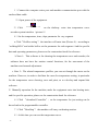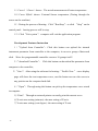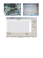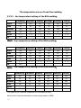
1
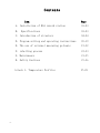
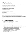
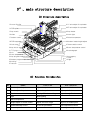
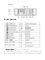
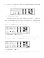
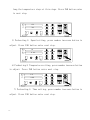
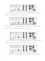
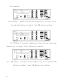
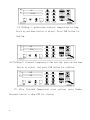
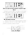
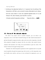
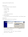
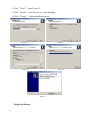
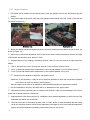
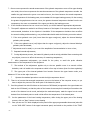
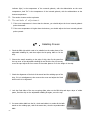
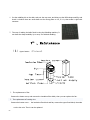
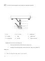
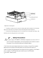
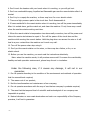
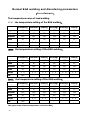
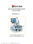
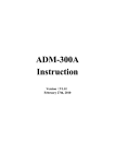
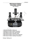
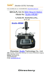
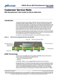
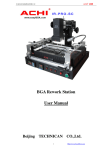
BGA Rework Station ZM-R5850
Manual
Preface
Dear customer, Thank you for using the BGA rework station ZM-R6820G of Shenzhen
Zhuo Mao Technology Co., Ltd.
Features of ZM-R5850 :
1. Unique design of three heating areas operating independently to control
temperature more accurately.
2, First / second temperature areas heat independently, which can set up 8 rising
temperature segments and 8 constant temperature segments to control. It can save 10
groups of temperature curves at the same time.
3. The third area uses far-infrared heater to preheat and control the temperature
independently, so that the PCB can be fully preheated during the desoldering process
and it can be free from deformation.
4. Choose imported high-precision K-Sensor and closed-loop to detect the
up/down temperature precisely.
5. After finishing desoldering & soldering, there is an alarming. When the
temperature goes beyond control, the electric circuit can cut off automatically, with
over-heating protection.
6. Use a powerful cross-flow fan to cool the PCB rapidly to prevent it from
deformation and ensure the welding effect.
7. Use a V-groove equipped with a flexible fixture for PCB positioning to protect
the PCB from deformation when heated or cooled.
8. This machine can be connected to a computer to be controlled more
conveniently with a built-in PC serial port and proprietary software attached to it.
9. For large thermal capacity of PCB/CSP/QFP or other high-temperature and
lead-free welding requirements, all can be handled easily.
10. The hot air nozzle can rotate 360 ° freely and it's easy to replace. Offering
BGA nozzles of different sizes for you to replace easily. Nozzles of special
requirements are customzible.
-1-
Shenzhen ZhuoMao Technology Co., Ltd. is a high-technology company located in the western
district of BaoAn. Thanks to its proximity to the international airport and container terminal, this part
of the booming industrial city of Shenzhen is rich in modern business opportunities.
BGA repair turnkey solutions are the heart of ZhuoMao activities. A strong R&D team supports
a dynamic workforce of over fifty people. A well established sales network and after-sales service has
built ZhuoMao a strong reputation in China among high profile customers.
The main products of ZhuoMao are BGA Rework Station (BGA Mounting, BGA Reballing
Machine, and BGA Soldering Machine), BGA Testing Machine (main board testing, video card
testing, digital camera testing, mobile chip testing, and various of ICT, FCT, ATE precise air/hand
testing machines )
Devoted to put in practice the motto “Specialized, Innovative and Dedicated”, the company is
focused on its customer’s satisfaction and has set up a network of local offices to tailor its offer to an
expanding market.
Developing new solutions to help customers tackle issues always more diverse and complex
keeps ZhuoMao engineering teams to the forefront of the technology and rewards its products with
the most prestigious awards and recognition in China.
Because ZhuoMao understands BGA repair is a critical activity needing speed, accuracy and
user-friendliness, its machines are designed for you to REGAIN SATISFACTION.
-2-
Contents
Item
-3-
Page
A、Installation of BGA rework station
03-03
B、 Specifications
03-03
C、Introduction of structure
04-04
D、Program setting and operating instructions
05-19
E、The use of external measuring galvanic
19-22
F、reballing process
22-23
G、Maintenance
23-25
H、Safety Cautious
25-26
Attach 1、Temperature Profiles
27-28
1st 、Installation
In order to ensure the validity of BGA Rework Station, the installation
should meet the following requirements.
a. Away from inflammable and explosives;
b. Away from water and other liquids;
c. Ventilated, dry place;
d. Stable and flat, free from tremor.
e. Less dust;
f. No heavy objects on the controlling box;
g. Not affected by airflow of air conditioner, heater or ventilator.
h. Leave a space of 30cm or more behind the rework station for the upper
part to move and rotate.
2nd 、Specifications
1、Power supply : AC220V±10%
50/60Hz
2、Power consumption: 4.8KW
3、Heater: Main heater: 0.8KW
Sub heater: 1.2KW heating element: 2.7KW ,others:0.1KW
4、Electric material: PLC,support computer communication.
5 、 Temperature control: K-type closed-loop thermocouple, top and
bottom heating independently, temperature error ±3°.
6、Positioning: V-groove fixture for PCB positioning
7、PCB size: MAX 410×370mm
Min 22×22
8、Machine dimension:710×680×660mm
9、Weight:40kg
10、Machine color:Black
-4-
3rd 、main structure description
(1) Structure description
r
e
t
a
e
h
p
o
t
f
o
t
s
u
j
d
a
s
i
x
a
Y
1
0
n
a
f
w
o
l
f
s
s
o
r
c
3
1
r
e
t
a
e
h
p
o
t
f
o
t
s
u
j
d
a
s
i
x
a
Z
2
0
t
n
i
l
p
s
B
C
P
4
1
r
e
t
a
e
h
p
o
t
3
0
e
l
z
z
o
n
p
o
t
5
1
t
h
g
i
l
k
r
o
w
4
0
r
e
d
i
l
s
6
1
e
r
u
t
a
r
e
p
m
e
t
k
c
o
l
b
5
0
e
l
z
z
o
n
m
o
t
t
o
b
7
1
t
s
u
j
d
a
t
h
g
i
e
h
r
e
t
a
e
h
m
o
t
t
o
b
6
0
r
e
t
r
o
p
p
u
s
B
C
P
8
1
l
o
r
t
n
o
c
c
i
t
a
t
s
o
m
r
e
h
t
7
0
w
e
r
c
s
k
c
o
l
9
1
l
o
r
t
n
o
c
e
r
u
t
a
r
e
p
m
e
t
r
e
v
o
8
0
t
s
u
j
d
a
r
i
a
t
o
h
p
o
t
0
2
h
p
a
r
g
a
l
u
c
l
a
c
9
0
g
u
l
p
Cn
/u
T
r
12
22
e
r
u
t
a
r
e
p
m
e
t
r
e
v
o
3
2
y
c
n
e
g
r
t
e
r
a
mt
es
01
11
t
a
t
s
o
m
r
e
h
t
e
l
b
a
m
m
a
r
g
o
r
p
p
o
t
4
2
g
n
i
l
o
o
c
6
2
t
h
g
i
l
2
1
t
a
t
s
o
m
r
e
h
t
e
l
b
a
m
m
a
r
g
o
r
p
m
o
t
t
o
b
5
2
m
u
u
c
a
v
7
2
(2) Function introduction
NO
Name
Function
Use method
1
Y-axis adjust of top heater
Adjust the top heater
Right-back,left-forward
2
Z-axis adjust of top heater
Adjust the top heater
Right-up,left-down
3
Top heater
Heating BGA when welding
Adjust through Z-axis
4
light
Work lighting
5
Block temperature
6
Height adjust of bottom heater
Adjust the lower height
Adjust to a suitable place
7
thermostatically control
To set the procedures
Over-temperature control
8
Over-temperature control
-5-
According to setting
9
calculagraph
10
stop
11
Start switch
12
Lighting switch
13
Crow-flow fan
Cool the PCB after heating
14
PCB splint
To hold up PCB board
15
Top nozzle
Make hot air focus on BGA
16
Slider
Lock screw to support PCB
17
Bottom nozzle
Lower heating when welding
18
PCB board supporter
19
Locking screw
To fix the splint
20
Top hot-air adjust
Adjust the top hot air
21
T/C plug
To measure the true temp.
22
run
To show it is heating
23
Over-temperature
24
Top programmable thermostat
25
Bottom programmable thermostat
26
Cooling switch
27
Vacuum switch
4
th
、 Program
Make a suitable place to BGA
Turn left and right
setting and operating instructions
(1) Program setting:
Meter setting:
Top/bottom PLC are using same meter, some using.
PLC appearance:
-6-
PLC panel instruction
Setting process:
1)
First turn on the power supply
Choose temperature profile: (set groups) press PTN button (can
save 10 groups temperature profiles), Press PTN groups will be changed
-7-
(1, 2,3,4,5 …0) choose one of them for temperature profiles (We take
st
1
group for example)
PV
D IS P
SV
T IM E
COM
MV
MAN
SV
A L1
SET
PRO G
1
RUN
P IN
PRO
STEP
O UT1
RUN
AUTO
HAND
P IN
PAR
SET
O UT2
A LTEC
PC410
2) Preheating: Slope(r)
Press SET button enter into temperature curve,r1 stands for
slope (the temperature will rise at the speed of 3℃ in one second)
3.00 stands for 3℃/second, press number increase button to
adjust. Press PAR button enter next step.
PV
r1
SV
D IS P
T IM E
COM
SET
3 .0 0
1
PRO G
RUN
P IN
PRO
STEP
MV
M AN
SV
AL1
O UT1
RUN
AU TO
HAND
P IN
PAR
SET
O UT2
PC410
ALTEC
3) Preheating:
Temperature (L),
Press number increase button to adjust,160 stands for preheating
temperature 160℃. Press PAR button enter to next step.
PV
L1
SV
D IS P
T IM E
COM
MV
MAN
SV
AL1
SET
1 6 0 .0 0
1
P IN
PROG
RUN
PRO
STEP
O U T1
PC410
4) Preheating:
RUN
AUTO
HAND
P IN
PAR
SET
O U T2
A LT E C
Time (d),
Press number increase button to adjust, D stands for the time how
-8-
long the temperature stays at this stage. Press PAR button enter
to next step.
PV
d1
SV
D IS P
T IM E
COM
SET
30
1
PROG
RUN
P IN
PRO
STEP
MV
MAN
SV
A L1
O UT1
RUN
AUTO
HAND
P IN
PAR
SET
OUT2
ALTEC
PC410
5) Preheating 2: Speed setting, press number increase button to
adjust. Press PAR button enter next step.
PV
r2
SV
D IS P
T IM E
COM
MV
M AN
SV
AL1
SET
3 .0 0
1
PROG
RUN
P IN
PRO
STEP
O UT1
RUN
AUTO
HAND
P IN
PAR
SET
OUT2
PC410
ALTEC
6) Preheating 2: Temperature setting, press number increase button
to adjust. Press PAR button enter next step.
PV
L2
SV
D IS P
T IM E
COM
SET
185
1
P IN
PROG
RUN
PRO
STEP
MV
MAN
SV
AL1
O UT1
RUN
AUTO
HAND
P IN
PAR
SET
O U T2
PC410
ALTEC
7) Preheating 2: Time setting, press number increase button to
adjust. Press PAR button enter next step.
-9-
PV
d2
SV
D IS P
T IM E
COM
MV
MAN
SV
AL1
SET
30
1
PRO G
RUN
P IN
PRO
STEP
OUT1
RUN
AUTO
HAND
P IN
PAR
SET
OUT2
PC410
ALTEC
8) Preheating 3: Speed setting, press number increase button to
adjust. Press PAR button enter next step.
PV
r3
SV
D IS P
T IM E
COM
SET
3 .0 0
1
PRO G
RUN
P IN
PRO
STEP
MV
MAN
SV
AL1
O UT1
RUN
AUTO
HAND
P IN
PAR
SET
O U T2
PC410
ALTEC
9) Preheating 3: constant temperature setting, press up and down
button to adjust. Press PAR button for confirm.
PV
L3
SV
D IS P
T IM E
COM
MV
MAN
SV
AL1
SET
210
1
PRO G
RUN
PIN
PRO
STEP
OUT1
RUN
AUTO
HAND
P IN
PAR
SET
O UT2
PC410
ALTEC
10) Preheating 3: constant temperature time setting; press up
and down button to adjust. Press PAR button for confirm.
PV
d3
SV
COM
MV
MAN
SV
AL1
SET
30
1
P IN
PC410
D IS P
T IM E
PROG
RUN
PRO
STEP
O U T1
RUN
AUTO
HAND
P IN
PAR
SET
OUT2
A LTEC
11 Welding 4, press number key to change, Press PAR button
- 10 -
For confirm.
PV
r4
SV
D IS P
T IM E
COM
SET
3 .0 0
1
PROG
RUN
P IN
PRO
STEP
MV
M AN
SV
A L1
O U T1
RUN
AUTO
HAND
P IN
PAR
SET
OUT2
PC410
ALTEC
12) Welding 4: preheating constant temperature setting, press
Up and down button to adjust. And PAR button confirm.
PV
L4
SV
D IS P
T IM E
COM
SET
225
1
PROG
RUN
P IN
PRO
ST EP
MV
M AN
SV
AL1
OUT1
RUN
AUTO
HAND
P IN
PAR
SET
O UT2
A LT EC
PC410
13) Welding 4: constant temperature time setting. press up/
down button to adjust. Press PAR button confirm.
PV
d4
SV
COM
SET
35
1
P IN
PC410
14)
D IS P
T IM E
Welding 5:
PROG
RUN
PRO
STEP
MV
MAN
SV
AL1
O UT1
RUN
AUTO
HAND
P IN
PAR
SET
OUT2
A LTEC
the speed of heating setting. Press up and down
button to adjust. Press PAR button for confirm.
- 11 -
PV
r5
SV
D IS P
T IM E
COM
SET
3 .0 0
1
PROG
RUN
PIN
PRO
STEP
MV
MAN
SV
AL1
O UT1
RUN
AUTO
HAND
P IN
PAR
SET
O UT2
PC410
A LTEC
15) Welding 5: preheating constant temperature setting,
Press up and down button to adjust. Press PAR button for
Confirm.
PV
L5
SV
D IS P
T IM E
COM
SET
230
1
PROG
RUN
P IN
PRO
STEP
MV
MAN
SV
A L1
O UT1
RUN
AUTO
HAND
PIN
PAR
SET
OUT2
PC410
ALTEC
16) Welding 5: Constant temperature time setting, press up and down
button to adjust. And press PAR button for confirm.
PV
d5
SV
D IS P
T IM E
COM
SET
25
1
P IN
PROG
RUN
PRO
STEP
MV
MAN
SV
AL1
O UT1
RUN
AUTO
HAND
P IN
PAR
SET
O UT2
PC410
A LTEC
17) After finished Temperature curve setting, press Number
Decrease button to show END for closing.
- 12 -
PV
r8
SV
D IS P
T IM E
COM
SET
End
1
PROG
RUN
P IN
PRO
MV
MAN
SV
A L1
OUT1
STEP
RUN
AUTO
HAND
P IN
PAR
SET
OUT2
PC 410
ALTEC
(Note: If you need to increase the temperature then press the upper
button)
18) When the setting finished, it will show as the following
picture. (This function stands for Max. temperature, do not modify)
PV
Hb
SV
D IS P
T IM E
COM
SET
300
1
P IN
PROG
RUN
PRO
MV
MAN
SV
AL1
O UT1
STEP
RUN
AUTO
HAND
P IN
PAR
SET
O UT2
PC410
A LTEC
REX--C10 Temperature controller:
Thermostat setting; top over temperature controller; bottom
over temperature controller are adopted REX-C10 temperature
controller, so the usage of them are the same.
e
r
u
t
a
r
e
p
m
e
t
l
a
u
t
c
a
o
w
h
s
e
r
u
t
a
r
e
p
m
e
t
g
n
i
t
t
e
s
w
o
h
s
PV
n
o
t
t
u
b
e
s
a
e
r
c
e
d
r
e
b
m
u
n
n
o
t
t
u
b
e
s
a
e
r
c
e
d
r
e
b
m
u
n
SV
n
o
t
t
u
b
e
s
a
e
r
c
n
i
r
e
b
m
u
n
t
e
s
S ET
RKC
- 13 -
R EX -C 1 0
Setting Method:
1) Hold down the adjustment button for 1-2 seconds, then the setting of the
temperature a bit flash, press numerical increase (decrease) key to change.
And then move button to move the modified adjusted value of 10, and
finally to 100, after finished, press the SET to confirm.
Infrared constant temperature settings
Proposal setting
:180℃
PV
30
SV
180
SET
RKC
REX-C10
(2): The use of the external computer
The device can connect with an external computer, you can observe two
temperature curves of the head of internal heating wire and external measurement of
galvanic through the computer interface, and you also can set the temperature, time and
other parameters through the computer, but also can achieve data transfer between
computer and instrument, store many curves and facilitate to print out. (Note: This
feature is limited to the upper heating control)
Statement: the related temperature parameters of the equipment can be set-up and
stored completely through the instrument age, but in order to set the temperature more
user-friendly, more intuitive, and easy to store, and print the temperature curve, our
- 14 -
company specially developed this software
Software Install
1)Lowest requirement for computer configuration.
a. CPU:P Ⅲ 800
b. Memory:128M
c. Video Card:4M
d. CD ROM
e. Serial Communication Interface
2)Software Installation,
a
Put the video into the video card, open CD diver,run“V2.08setup” appear
language select.
Choose” English” and Click “Next” to enter Picture 1
Picture 1
Picture 2
b Click“Next”to enter Picture 2
c After enter “Picture 2”,click“Next” button,enter Picture 3
d Click“Next”
,enter Picture 4
- 15 -
e Click“Next”,enter Picture 5
f Click“Install”
,enter Picture 6,start installing.
g Click“Finish”
,finish installing process.
Picture 3
Picture 4
Picture 5
Picture 6
Picture 7
Using of software
- 16 -
1)Connect the computer series port and machine communication port with the
enclosed date cable.
2)Open power of the equipment.
3)Click
Zhuomao reworker.lnk
on the desktop,enter into temperature curve
recorder system interface(picture 8)
4)Set the temperature, time, slope parameter for very segment.
a Click“Profiles setting”
,the interface will enter into (Picture 9),according to
“welding BGA” and solder ball to set the parameter for each segment. And for specific
date and operating parameters, please see the construction book for reference.
b Note 1:This software is for showing the temperature curve and recorder, the
software does not have the motion control functions, for the movement of the
machine need manual adjustment.
c Note 2:The related temperature profiles, you can set through the meter on the
machine. However, in order to facilitate the users for temperature setting, in particular
for the temperature curve showing, save and print, so we develop and expand this
software.
5)Manually operation for the machine, make the equipment enter into heating state,
and for specific operation, please see the construction book for reference.
6)Click “download Controller” ,so the temperature for just setting can be
down load to the programmable controller.
7)Click“Run/Stop”
,the machine will carry out heating motion.
8)At this time you can see the temperature curve.
- 17 -
9)Curve 1(Green)shows:The actual measurement of heater temperature
10)Curve 2(Red)shows:External Sensor temperature (Testing through the
sensor on the machine)
11)During the process of heating,Click“Run/Stop”
,or click “Stop”on the
control panel,heating process will be stop.
12)Click“Exit system”
,computer will exit the application program.
Development Features Instruction
1 )“ Upload from Controller” : Click this button can upload the internal
instrument parameter from controller to the computer; it can set a group of data each
click.(Note: the programmable controller can save 10 groups itself)
2)
“download Controller”: Click this button can download the parameter from
computer to the controller;
3)
“Save”
:After using the software for heating,
“Profile View” curve display
page will show the two temperature curve, use this button can save the curves to
any position on the computer hard disk.
4)
“Open”
:Through using this button can pick up the temperature curve stored
in computer.
5) “Print”:Through an external printer can easily print the current curve.
6) X-axis max setting (minutes): the max setting of X-axis.
7) Y-axis max setting (cent degree): the max setting of Y-axis.
- 18 -
Picture 8
Picture 9
Picture 10
- 19 -
Picture 11
5th 、
The use of external measuring galvanic
( 1) Function
1、More accurate to measure the actual temperature of the part to be heated during the welding process.
2、It is easy to move, so that it can be convenient to measure the temperature of the different parts of the
welded components during the heating process.
3、Calibration role, through appropriate adjustment, it will make the temperature of the welding parts get
close to the set temperature as much as possible.
( 2) Installation
1、Check the galvanic lines, whether there are disconnected phenomena or not.
2、Insert the galvanic Plug into the "outer galvanic Socket” on the control panel according to the positive
and negative mark.
3、After GALVANIC installed correctly, click "DiSP SELE" button on the upper instrument panel, (the button
which is used to switch the displaying item), switch to "TIME", the corresponding galvanic current
temperature will be displayed in the second line of instrumentation on the
"SV" display window.
Stated: "DiSP SELE" is the button to switch the displaying items, when press it, the downstream sequence
of display windows display setting no., output no., the remainder of the number of segments of running,
corresponding to Panel "SV", "MV", "TIME "indicator light.
- 20 -
( 3) measurement
1、PCB board will be installed on the rework station, with the galvanic fixed on the PCB board using foil
stickers.
2、Adjust the height of the probe; With the probe galvanic head located in the top 1-2mm of the test site
(as shown in Figure 12)
Picture 12
Picture 13
3、Adjust the related mechanical adjustment knob, so that the heating part just below the hot-air tube. (as
shown in Figure 13)
4、Adjust the up and down adjustment knob of the hot-air head to make the distance between the edge
of PCB board side and the hot-air head is 3-5mm.
5、Implementation of the welding / disordering process, that is to start the process of upper and lower
heater.
6、Then it will show two curves of the green and red on the computer monitor screen
7、Curve 1, the actual measurement temperature of the internal galvanic of the top heater (green)
8、Curve 2, the actual measurement temperature of the external galvanic curve (red)
(4)Using the outer galvanic to adjust the temperature curve
Statement: In this operation, it may be due to improper operation to cause the temperature deviation
of the device or even lose control, please caution!
Take the upper hot-air tube as an example to make detailed description of adjustment method
1、Set the temperature, the time, the slope and so on parameters of the upper heater
2、Adjustment process proposed to do on a waste circuit board in order to prevent damage to the circuit
board and on-board electronic components.
3、Implementation of the above process (3), installed the outer measured galvanic, in which the top of the
PCB board just below the hot-air tube.
4、Close the lower part of the heating process, click on "Start" button to start the heating process, which
will on the computer monitor screen will be displayed on the upper curve of the measured temperature
(green) and external galvanic measuring temperature (red) the two curves
- 21 -
5、Green curves represent the actual measurement of the galvanic temperature curve of the upper heating
wire inside, the red curve represents the actual measurement of the galvanic temperature outside. the
smaller the gap between the green curve and red curve, the closer between the actual temperature
and set temperature of the heating parts, more standard of the upper heating process; On the contrary,
the greater the gap between the two curves, the greater the actual temperature deviate from the set
temperature, the more non-standard of the upper part during the heating process.
6、If the deviation between the two curves is too much, you should make the appropriate adjustments
7、The specific adjustment method is as follows, because of the impact of the system processes and the
environmental, deviations in the objective is inevitable. If the temperature deviation does not affect
the normal welding and desordering, non-professionals should avoid the following corrective actions!
A
If the outer galvanic curve (red) lower than the upper one(green), adjust the internal hairdryer
galvanic probe upward;
B
If the outer galvanic curve (red) higher than the upper one(green), adjust the internal hairdryer
galvanic probe downward;
C
D
E
Adjustment must be small, try to control the amplitude of accommodation in 1mm or less;
Repeated several adjustments;
During adjustment process, the heated of galvanic probe is strictly prohibited from contacting with
any objects, so as not to affect the accuracy of measuring temperature;
F
After temperature adjustment, you should fix the probe, to avoid the probe vibration
measurement of the temperature of the equipment
G
The method of the adjustment applies only to the two parallel curves in a smooth uniform
deviation, and it is invalid to the temperature which is from top to bottom jitter free-laws regulating!
H
The upper part of the internal galvanic Duct location: Remove the upper heater nozzle, at a
distance of 2-3cm at the edge wind-cone .
Operate the standard procedure to avoid the high-temperature burns!
I
8、There is no booster thermocouple temperature curve on the bottom of the computer screen, so you
have to adjust the process of the lower part of the heaters by visual.
9、fixed the galvanic line with foil stickers on the bottom of PCB board (as opposed to the upper heater set
back on the PCB board), so that the probe of the booster thermocouple is located just 2mm above the
mouth of the bottom hot-air nozzle, and adjust the mechanical parts, make the upper hot-air nozzle
deviate from the heated parts to avoid cold air affect the temperature of the heated parts.
10、Set the parameters of the lower heating temperature, while closing the upper part of the heating
process, click on "Start" button to start heating
11、Now you can see "SV” which displayed on the panel of the upper programmable thermostat (also click
on the "DiSP SELE" button of the upper instrument panel, and switch to the position of the "TIME"
- 22 -
indicator light) is the temperature of the external galvanic, with the abbreviation as the outer
temperature; And “PV” is the temperature of the internal galvanic, with the abbreviation as the
bottom temperature.
12、The caution is same as the top heater.
13、The methods of adjustment:
A If the outer temperature is lower than the bottom, you should adjust the lower internal galvanic
probe downward.
B
If the outer temperature is higher than the bottom; you should adjust the lower internal galvanic
probe upward.
6 th 、 Reballing Process
1. Fixed the BGA chip which need to be reballed on the under plate of the
adjustable reballing kit, and then adjust the No-spring slider to fix the
chip.
2. Choose the stencil according to the style of chip, then fix the stencil on
the top cover of the adjustable reballing kit and lock the four M3 screws,
cover the cap. Adjust the four screws of the under plate to fit for the height of the chip.
3. Check the alignment of the hole of the stencil and the welding spot of the
chip, if it is in misalignment, then remove the cover and adjust the fixed
slider until it is in alignment.
4. Lock the fixed slider of the two no-spring slider, take out the BGA chip and wipe a layer of solder
paste, fixed the chip on the adjustable reballing kit again, cover the cap.
5. Put some solder balls into the kit, clutch and shake it to make all the balls
stand on the welding spot, and at the same time, clear the superabundant
balls.
- 23 -
6. Put the reballing kit on the desk, take out the top cover, and bring out the BGA cheap carefully, and
check it whether there are some balls on the wrong place or not, if it is, then make it right with
tweezers.
7. The way of making the balls fixed is using the Reballing machine, It
can heat the cheap medially. Up to now, we finished reballing.
7 th 、Maintenance
(1)Upper heater:(Pictured)
1. The replacement of fan:
Remove the heater cover, and remove the insulation fiber block, then you can replace the fan.
2. The replacement of heating wire
Remove the heater cover 、the insulation fiber block and fan, remove the upper fixed block, then take
out the hot wire. Then it can be replaced.
- 24 -
(2)
The lower (second temperature zone) heating wire replacement (pictured)
01
02
03
04
07
08
05
09
06
02 Heating Duct
01 body
03
Heating wire
04 Fan Holder
05
fan
06
Heater cover
07 Fan Holder Bolt
08
Fan Bolt
09
Heater cover bolts
Replacement of the lower hot air heating wire:
1
Remove the heater bolts, and then remove the heater cover,
2
Demolition of fans and fan mounts, remove the hot wire. Then you can replace the
heating wire,
(3)The bottom heating panel (pictured)
- 25 -
heating pad
lock screw
fixed plate
heating panel card
heating box
Replacement of heating plate:
1. Demolition of locking screws (4), remove the heating plate and the assembly of the fixed plate,
placed on the table which is covered with a sponge (with heating plate surface facing down).
2.
Removed the fixed heating plate card, you can break down the fixed plate and heating
plate
assembly, remove the heating plate then it can be replaced.
8 th 、 Safety Precautions
!The power supply of ZM-R6820G is AC220V,the temperature can arrive to 400℃.If
you do not operate inappropriately, it will cause damaging to the machine or even to
the operator. So you must strictly abide by the following matters:
1. Don't blow to the rework station directly when it is working, or there will be a negative
difference from the surface of the heating board, thus some parts will be burnt out.
2. After it is started, the high temperature area should not touch any objects, or it will lead to
a fire or explosion. The PCB and other parts should be put on the PCB bracket.
3. No vibration. Handle it gently.
- 26 -
4. Don't touch the heaters with your hands when it is working, or you will get hurt.
5. Don't use combustible spray, liquefied and flammable gas near the rework station after it is
started.
6. Don't try to re-equip the machine, or there may be a fire or an electric shock.
7. There are high-pressure parts in the circuit box. Don't disassemble it.
8. If some metals fall in the rework station when it is working, turn off the power immediately.
After it is cooled down, get the metal out, and clean the machine. If not, there may a smell
when the machine starts working next time.
9. When the rework station's temperature rises abnormally or smokes, turn off the power and
inform the service technicians to repair it. Turn off the power of the circuit box and the
machine while moving the rework station. Hold the plug when we remove the wire or it will
lead to a poor contact then the machine can't work very well.
10. Turn off the power when stop using it.
11. Don't put the rework station on the wires, or there may be a failure, a fire, or an
electric shock.
12. Before you use the machine, you must read the instructions attentively.
Note: when the machine works, it will produce some smell. So ensure the comfortable,
healthy and safe operation environment, please keep the air in circulation.
Under the following case, if it causes any damage, it will not in our
guarantee;
1)Do not operate according to the condition of the environment and methods of operation
that the manual book required;
2)The reason out of our product;
3)Not the transformation and maintenance of our company;
4)Do not operate accordance with the way of use that our company's products required;
5)The case that the temporal level of scientific and technological of our company was
impossible to predict;
6)Natural disasters or man-made destruction and such non-responsibility of the Company
premises, it will not in guarantee.
- 27 -
Normal BGA welding and disordering parameters
( for reference)
The temperature curve of lead welding
41*41 the temperature setting of the BGA welding:
preheating insulation
heating
welding1 welding2
cooling
upper
160
185
210
235
240
225
time
30
30
35
40
20
15
bottom
160
185
210
235
240
225
time
30
30
35
40
20
15
slope
3.0
3.0
3.0
3.0
3.0
3.0
IR
180
38*38
the temperature setting of the BGA welding:
preheating insulation
heating
welding1 welding2
cooling
upper
160
185
210
225
235
215
time
30
30
35
40
20
15
bottom
160
185
210
225
235
215
time
30
30
35
40
20
15
slope
3.0
3.0
3.0
3.0
3.0
3.0
IR
185
31*31
the temperature setting of the BGA welding:
preheating insulation
heating
welding1 welding2
cooling
upper
160
180
200
215
225
215
time
30
30
35
40
20
15
bottom
160
180
200
215
225
215
time
30
30
35
40
20
15
slope
3.0
3.0
3.0
3.0
3.0
3.0
IR
180
The upper is the reference temperature of the lead BGA。
- 28 -
The temperature curve of Lead-free welding
41*41
the temperature setting of the BGA welding
preheating insulation
heating
welding1 welding2
cooling
upper
165
190
225
245
255
240
time
30
30
35
55
25
15
bottom
165
190
225
245
255
240
time
30
30
35
55
25
15
slope
3.0
3.0
3.0
3.0
3.0
3.0
IR
210
38*38
the temperature setting of the BGA welding:
preheating insulation
heating
welding1 welding2
cooling
upper
165
190
225
245
250
235
time
30
30
35
45
25
15
bottom
165
190
225
245
250
235
time
30
30
35
45
25
15
slope
3.0
3.0
3.0
3.0
3.0
3.0
IR
210
31*31
the temperature setting of the BGA welding:
preheating insulation
heating
welding1 welding2
cooling
upper
165
190
220
240
245
235
time
30
30
35
40
20
15
bottom
165
190
220
240
245
235
time
30
30
35
40
20
15
slope
3.0
3.0
3.0
3.0
3.0
3.0
IR
210
The upper is the reference temperature of the lead-free BGA
Such as set 0 when the demolition of the cooling section of BGA
- 29 -