1
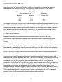
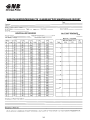
®
GNB Industrial Power –
The Industry Leader.
®
®
GNB Industrial Power, a division of Exide Technologies, is a
global leader in network power applications including
communication/data networks, UPS systems for computers
and control systems, electrical power generation and
distribution systems, as well as a wide range of other
industrial standby power applications. With a strong
manufacturing base in both North America and Europe and a
truly global reach (operations in more than 80 countries) in
sales and service, GNB Industrial Power is best positioned to
satisfy your back up power needs locally as well as all over
the world.
Based on over 100 years of technological innovation the
Network Power group leads the industry with the most
recognized global brands such as ABSOLYTE®, GNB®
FLOODED CLASSIC®, MARATHON®, ONYX™, RELAY GEL®,
SONNENSCHEIN®, and SPRINTER®. They have come to
symbolize quality, reliability, performance and excellence in
all the markets served.
INSTALLATION
&
OPERATING
INSTRUCTIONS
GNB Industrial Power takes pride in its commitment to a
better environment. Its Total Battery Management program,
an integrated approach to manufacturing, distributing and
recycling of lead acid batteries, has been developed to
ensure a safe and responsible life cycle for all of its products.
GNB Industrial Power
USA – Tel: 888.898.4462
Canada – Tel: 800.268.2698
www.gnb.com
SECTION 92.30 2012-07
A Division of Exide Technologies
SECTION 92.30 2012-07
INDEX
Page
Section 1 - GENERAL INFORMATION
1.0
Marathon/Sprinter/SUNlyte Batteries
Section 2 - SAFETY PRECAUTIONS
2.0
2.1
2.2
2.3
2.4
Safety Alert
Sulfuric Acid Burns
Explosive Gases
Electrical Shock and Burns
Important Message
Section 3 - RECEIPT OF SHIPMENT
3.0
3.1
Delivery Inspection
Concealed Damage
Storage Location
Storage Interval
Section 5 - GENERAL INSTALLATION CONSIDERATIONS
5.0
5.1
5.2
5.3
5.4
5.5
Battery Location
Ventilation
Temperature Variations
Floor Loading
Floor Anchoring
Open Circuit Voltage Check
Section 6 - RACK SYSTEM - INSTALLATION
6.0
1
1
1
1
2
2
3
Section 4 - STORAGE PRIOR TO INSTALLATION
4.0
4.1
1
Placement of Units
(continued on next page)
i
3
3
3
3
4
4
4
4
4
INDEX (continued)
Page
Section 7 - ELECTRICAL INSTALLATION CONSIDERATIONS
7.0
7.1
7.2
7.3
7.4
7.5
7.6
7.7
7.8
Connecting Cables
Paralleling
Connection Preparation
Torqueing
Connections
Connection Check
Battery To Charger Connection
Connection Resistance
Cell Numerals
Section 8 - INITIAL CHARGE
8.0
Constant Voltage Initial Charge
Section 9 - OPERATION
9.0
9.1
9.2
9.3
9.4
9.5
9.6
9.7
Float Charge
Float Voltages
Voltmeter Calibration
Recharge
Determining State of Charge
Effects of Temperature
Effects of Float Voltage
Ohmic Measurements
Section 10 - EQUALIZATION
10.0
10.1
Equalizing Charge
Equalizing Frequency
5
5
5
5
6
6
6
7
7
7
8
8
9
10
10
10
11
12
12
12
Section 11 - MAINTENANCE SCHEDULE
13
Section 12 - TAP CONNECTIONS
13
Section 13 - TEMPORARY NON-USE
13
Section 14 - UNIT CLEANING
14
Battery Maintenance Report Template
ii
SECTION 1 - GENERAL INFORMATION
1.0 MARATHON/SPRINTER/SUNLYTE BATTERIES
In normal use, the battery will not generate or release hydrogen gas or acid mist, and will not leak
acid. However, there is the possibility that under abnormal operating conditions hydrogen gassing,
acid mist, and leaking electrolyte could occur. Thus GNB® Industrial Power recommends that
Section 2 of these instructions entitled “SAFETY PRECAUTIONS” be reviewed thoroughly and
strictly followed when working with batteries.
The safety alert symbol at left appears
throughout this manual. Where the symbol
appears, obey the safety message to avoid
personal injury.
SECTION 2 - SAFETY PRECAUTIONS
2.0 SAFETY ALERT
CAUTION
Before proceeding with the unpacking, handling, installation and
operation of this sealed lead-acid storage battery, the following
general information should be reviewed together with the
recommended safety precautions.
2.1 SULFURIC ACID
ELECTROLYTE BURNS
DANGER
SULFURIC ACID BURNS
"Warning: Risk of fire, explosion, or burns. Do not disassemble, heat above 50 degrees Celsius or
incinerate." Batteries contain dilute (1.310 nominal specific gravity) sulfuric acid electrolyte which
can cause burns and other serious injury. In the event of contact with electrolyte, flush immediately
and thoroughly with water. Secure medical attention immediately.
When working with batteries, wear rubber apron and rubber gloves. Wear safety goggles or other
eye protection. These will help to prevent injury if contact is made with the acid.
DANGER
2.2 EXPLOSIVE GASES
EXPLOSIVE GASES
Batteries could generate explosive gases, which when released, can explode and cause blindness
and other serious injury. If the safety vent opens while the explosive gases are being generated (e.g.,
in the event of a charger malfunction), these explosive gases will be released.
Keep sparks, flame and smoking materials away from the battery area and explosive gases.
DANGER
ELECTRICAL SHOCK
AND BURNS
2.3 ELECTRICAL SHOCK AND BURNS
All installation tools should be adequately covered with vinyl electrical tape or suitable nonconducting material to minimize the possibility of shorting across connections.
1
Never lay tools or other metallic objects on the batteries as shorting, explosions and
personal injury may result.
Multi-cell systems attain high voltages; therefore, extreme caution must be exercised during
installation of a battery system to prevent serious electrical burns or shock.
Loose or dirty connectors/connections can cause battery fires. Keep all connectors/ connections
clean and torques at proper values. Keep outside of batteries clean and dry. Neutralize any acid
corrosion with a cloth moistened with a solution of 1 lb. of baking soda to 1 gallon of water, then wipe
off all traces of soda.
Do not move or shift racks/cabinets once installed without first disconnecting load to rack/cabinet and
all inter-rack/cabinet connections. Consult wiring diagrams for location of these connections.
Do not lift cells by terminal posts. Do not tamper with post seals, protective covers, pressure relief
vents or other battery components.
Disconnect the AC and DC circuits before working on batteries or charging equipment.
Assure that personnel understand the risk of working with batteries, and are prepared and equipped
to take the necessary safety precautions. These installation and operating instructions should be
understood and followed. Assure that you have the necessary equipment for the work, including
insulated tools, rubber gloves, rubber aprons, safety goggles and face protection.
CAUTION !
If the foregoing precautions are not fully understood, clarification should be obtained
from your nearest GNB Industrial Power representative. Local conditions may introduce
situations not covered by GNB Industrial Power Safety precautions. If so, contact the
nearest GNB Industrial Power representative for guidance with your particular safety
problem before proceeding to install or service these batteries. Refer to applicable federal, state and local regulations as well as industry standards.
2.4 IMPORTANT MESSAGE
The symbol at left indicates an important
message. If not followed, damage to and/or
impaired performance of the battery may
result.
SECTION 3 - RECEIPT OF SHIPMENT
3.0 DELIVERY INSPECTION
Immediately upon delivery, examine for possible damage caused in transit. Damaged packing material could indicate rough handling. Make a descriptive notation on the delivery receipt before signing. If
cell or unit damage is found, request an inspection by the carrier and file a damage claim immediately. Any battery with post or seal damage should be replaced.
2
3.1 CONCEALED DAMAGE
Within 15 days of receipt, examine all batteries for concealed damage. If damage is noted, immediately
request an inspection by the carrier and file a concealed damage claim. Any delay in notifying carrier may
result in loss of right to reimbursement for damages.
SECTION 4 - STORAGE PRIOR TO INSTALLATION
4.0 STORAGE LOCATION
If the battery is not to be installed at the time of receipt, it is recommended that it be stored indoors in
a cool [25°C (77°F)], clean, dry location. Do not stack pallets or possible battery damage may occur.
4.1 STORAGE INTERVAL
The storage interval between the date of shipment and the date of initial charge should not exceed
six (6) months. The battery should be given a freshening charge (refer to Section 8 - Initial Charge)
before the end of the above stated storage interval. Storage at elevated temperatures will result in
accelerated rates of self discharge. A general rule of thumb is that for every 10°C (18°F) increase
above 25°C (77°F) the time interval for freshening charge should be halved. For example, if a battery
was stored at 35°C (95°F) the freshening charge time interval would be 3 months. If the battery was
stored at 30°C (86°F) the freshening charge time interval would be 4.5 months. Storage beyond
these periods without proper charge can result in excessive sulfation of plates which is detrimental to
battery performance and life.
SECTION 5 - GENERAL INSTALLATION CONSIDERATIONS
Prior to starting the installation of the MARATHON/SPRINTER/SUNLYTE battery system, a review of
this section is strongly recommended.
5.0 BATTERY LOCATION
It is recommended that the battery be installed in a clean, cool, dry location. Floors should be reasonably level and able to support the battery weight. A location having an ambient temperature of 25°C
(77°F) will result in optimum battery life and performance. Temperatures below 18°C (65°F) reduce
battery efficiency. Temperatures above 27°C (80°F) will result in a reduction of battery life.
Continuous operation above 50°C (122°F) is not recommended.
A designated aisle space should be provided to permit initial installation and future service or surveillance of the batteries.
5.1 VENTILATION
The MARATHON/SPRINTER/SUNLYTE battery is a valve regulated battery which under normal recommended charging in a stationary application does not vent any gases.
3
However, should the battery be subjected to excessive overcharge, hydrogen and oxygen can be
vented to the atmosphere. Therefore, the battery should NEVER BE INSTALLED IN AN AIRTIGHT
ENCLOSURE. Sufficient precautions must be taken to prevent excessive overcharge. Normal
ventilation sufficient for human occupation will be adequate to avoid hazardous conditions.
Tests have confirmed that more than 99% of gases generated are recombined within the battery.
Under normal operating conditions, no special ventilation and/or battery room is required.
MARATHON/SPRINTER/SUNLYTE batteries can be installed in close proximity to electronic equipment
only when the heat generated by this equipment is removed by ventilation.
5.2 TEMPERATURE VARIATIONS
Sources of heat or cooling directed on portions of the battery can cause temperature variations within the
strings resulting in cell voltage differences and eventual compromise of battery performance. Heat
sources, such as heaters, sunlight or associated equipment, can cause such temperature variations.
Similarly, air conditioning or outside air vents should not directly influence portions of battery string
temperatures. Every effort should be made to keep temperature variations within 3°C (5°F).
5.3 FLOOR LOADING
The area where the battery system is to be installed should have the capability to
support the weight of the battery as well as any auxiliary equipment. The total battery weight will
depend on the battery size, number of batteries, as well as the configuration involved. Prior to
installation, a determination should be made that the floor integrity is adequate to accommodate the
battery system.
5.4 FLOOR ANCHORING
Where seismic conditions are anticipated, floor anchoring should be provided. Such anchoring is the
responsibility of the user.
5.5 OPEN CIRCUIT VOLTAGE CHECK
The voltage of each unit should be checked to insure the average cell voltage is at least 2.1 volts. If
any unit has an average cell voltage lower than 2.1 volts, contact your local GNB representative for
instructions.
Example:
A 6 cell (12 V nominal) battery should have an open circuit voltage of
at least 2.1 x 6 = 12.6 VDC.
A 3 cell (6 V nominal) battery should have an open circuit voltage of
at least 2.1 x 3 = 6.3 VDC.
SECTION 6 - RACK SYSTEM - INSTALLATION
6.0 PLACEMENT OF UNITS ON RACK
When installing units on a rack, start on the lower tier for stability and safety reasons. Place units on
the rack so that the positive (+) of one unit is connected to the negative (-) of the next unit. Standard
spacing is 12mm (1/2 inch) minimum between units.
4
Determine the number of units to be placed on each row. If a row of units does not fill the entire rack
length, fill the remaining space with foam cell spacers in seismic installations.
SECTION 7 - ELECTRICAL INSTALLATION CONSIDERATIONS
7.0 CONNECTING CABLES: BATTERY SYSTEM TO OPERATING EQUIPMENT
Battery performance is based on the output at the battery terminals. Therefore, the shortest electrical
connections between the battery system and the operating equipment should be used for maximum
total system performance. A terminal plate kit should be utilized when connecting multiple cables to a
battery terminal post.
DO NOT SELECT CABLE SIZE BASED ON CURRENT CARRYING CAPACITY ONLY. Cable size
selection should provide the lowest voltage drop possible between the battery system and operating
equipment. Excessive voltage drop will reduce the desired support time of the battery system.
7.1 PARALLELING
Where it is necessary to connect battery systems in parallel to obtain sufficient capacity, cable
connections from the bus/load to each of the parallel strings is preferred rather than inter-string
paralleling. The maximum number of parallel strings recommended by GNB Industrial Power in high
rate applications is 4. High Rate applications are defined as those with loads that would discharge
the battery in 60 minutes or less.
Cables should be sized to minimize voltage drop, and for proper current carrying capability. They should be
as short as possible. Care should be taken to ensure the overall resistance of the connection between
batteries and equipment bus are consistent between strings.
7.2 CONNECTION PREPARATION
Gently clean contact surfaces only by using a brass suede brush or 3M Scotch Brite scouring pad,
being careful not to remove lead plating from inter-unit connectors. Immediately after contact areas
are cleaned, apply a thin coating of NO-OX-ID grease to these surfaces only.
7.3 CONNECTION TORQUEING
After cleaning contact surfaces, install all connectors hand tight to allow for final alignment of units.
Once final alignment is made, all connections should be torqued to the value shown on the battery
Complete connection of units by installing the inter-tier cables and terminal plates (when required).
Caution, do not make connections to the load at this time.
5
7.4 CONNECTIONS
Battery terminal and intercell connections should be corrosion free and tight for trouble-free operation. Periodically these connections should be inspected to ensure cleanliness and integrity.
CAUTION
DO NOT WORK ON CONNECTIONS WITH BATTERY
CONNECTED TO CHARGER OR LOAD
If corrosion is present, disconnect the connector from the terminal. Gently clean the affected area using a
brass suede brush or 3M Scotch Brite scouring pad, being careful not to remove lead plating from interunit
connectors. Apply a thin coat of NO-OX-ID grease to the cleaned contact surfaces. Re-install connectors
and retorque connections.
It is recommended that all terminals and intercell connections should be retorqued at least once
every year, per specifications shown on battery label.
Maintaining electrical integrity of connectors is important, since poor connections will result in
reduced battery output and, in extreme cases, may add to heating and could result in melted battery
posts, circuit interruptions, or battery fires.
7.5 CONNECTION CHECK
Visually check to see that all units are connected positive (+) to negative (-) throughout the battery
string.
Measure the total open circuit voltage from positive string termination to negative string termination. The
open circuit battery system voltage should be approximately 2.13 volts per cell multiplied by the number
of cells per unit, multiplied by the number of units in series. If the total is less than this value by more
than 10-12 volts, the possibility exists that one or more units may be incorrectly connected and all connections should be rechecked.
Example
A 24 cell (48 V nominal) battery system should have
an open circuit voltage of 2.13 x 24 = 51.12 VDC.
A 12 cell (24 V nominal) battery system should have
an open circuit voltage of 2.13 x 12 = 25.56 VDC.
Calculations for other configurations such as 60 cell, 180 cell, 240 cell, etc. follow the same procedure.
7.6 BATTERY TO CHARGER CONNECTION
The positive (+) terminal of the battery should be connected to the positive (+) terminal of the charger
and the negative (-) terminal of the battery to the negative (-) terminal of the charger. A terminal plate
kit should be utilized when connecting multiple cables to a battery terminal post.
6
7.7 CONNECTION RESISTANCE
Electrical integrity of connections can be objectively established by measuring the resistance of each
connection. These resistances are typically in the microhm range. Meters are available which
determine connection resistance in microhms. Be sure that the probes are touching only the posts to
insure that the contact resistance of connector to post is included in the reading.
Resistance measurements or microhm measurements should be taken at the time of installation and
annually thereafter. Initial measurements at installation become the bench mark values and should
be recorded for future monitoring of electrical integrity.
It is important that the bench mark value for all similar connections be no greater than 10% or 5
microhms, whichever value is greater over the average. If any connection resistance exceeds the
average by more than 10% or 5 microhms, whichever is greater, the connection should be remade so
that an acceptable bench mark value is established.
Bench mark values for connection resistances should also be established for terminal plates, where
used, as well as cable connections. Bench mark values should preferably be established upon
installation.
All bench mark values should be recorded. Annually, all connection resistances should be remeasured.
Any connection which has a resistance value 20% above its bench mark value should be corrected.
7.8 CELL NUMERALS
A set of pressure sensitive battery numerals and system polarity labels are supplied and should be
applied at this time.
Battery numerals should be applied to a visible location on the battery. Designate the positive terminal
battery as unit #1 with succeeding units in series in ascending order.
The system polarity labels should be applied next to the positive and negative terminals of the battery
string.
SECTION 8 - INITIAL CHARGE
8.0 CONSTANT VOLTAGE METHOD
Batteries lose some charge during shipment as well as during the period prior to installation. A battery
should be given its initial charge at installation.
Constant voltage is the only charging method allowed. Most modern chargers are of the constant voltage type.
Determine the maximum voltage that may be applied to the system equipment. This voltage, divided by
the number of cells connected in series, will establish the maximum volts per cell (VPC) that may be used.
7
Please reference Table A to determine the recommended charging parameters that the batteries should
undergo upon installation prior to commissioning testing. Either Profile A or Profile B may be implemented. Do not exceed the maximum current(s) shown in Section 9.3.
12V Nominal Monobloc
OCV
> 12.80 V
12.60 V - 12.80 V
12.30 V - 12.60 V
12.10 V - 12.30 V
6V Nominal Monobloc
OCV
> 6.4 V
6.30 V - 6.40 V
6.10 V - 6.30 V
6.03 V - 6.10 V
TABLE A
Profile A
12 hrs. at float voltage
24 hrs at 14.10 V or 12 hrs. at 14.40 V
24 hrs at 14.40 V
72 Hrs at 14.40 V
Profile A
12 hrs. at float voltage
24 hrs at 7.05 V or 12 hrs. at 7.20 V
24 hrs at 7.20 V
72 Hrs at 7.20 V
Profile B
**********
72 hrs at float voltage
168 hrs at float voltage
**********
Profile B
***********
72 hrs at float voltage
168 hrs at float voltage
***********
NOTE: Time periods listed in Table A are for temperatures from 21°C (70°F) to 32°C (90°F); for temperatures 13°C (55°F) to 20.5°C (69°F), double the number of hours. For temperatures other than
25°C (77°F) the following formula can be used to determine the recommended charge voltage
per cell (VPC):
V corrected = V25°C - [(T actual - 25°C) x (.0055 V/°C)] or
V corrected = V77°F - [(T actual - 77°F) x (.003 V/°F)]
Example at 29.4°C (85°F), OCV of 12.70 V, and 24 hr. charge target:
V corrected = 2.35-0.024
= 2.326 VPC
SECTION 9 - OPERATION
9.0 FLOAT CHARGE
In this type of operation, the battery is connected in parallel with a constant voltage charger and the
critical load circuits. The charger should be capable of maintaining the required constant voltage at
the battery terminals and also supply the normal load where applicable. This sustains the battery in a
fully charged condition and also makes it available to assume the emergency power requirements in
the event of an AC power interruption or charger failure.
9.1 FLOAT VOLTAGES
Following is the float voltage range recommended for the MARATHON/SPRINTER/SUNLYTE Battery
System. Select the “volts per cell” (VPC) value within the range listed that will result in the battery
series string having an average volts per cell equal to that value.
RECOMMENDED FLOAT VOLTAGE AT 77°F (25°C):
2.25 VPC to 2.30 VPC for Marathon & Sprinter
2.25 VPC to 2.35 VPC for SUNlyte
8
For temperatures other than 77°F (25°C), the following formula can be used to determine the recommended float charge voltage per cell:
V corrected = V25°C - [(T actual - 25°C) x (.0055 V/°C)] or
V corrected = V77°F - [(T actual - 77°F) x (.003 V/°F)]
Minimum float voltage (temperature corrected) is 2.21 VPC. Temperature correction does not apply
below this value.
Maximum float voltage (temperature corrected) is 2.40 VPC. Temperature correction does not apply
above this value.
Example
At 18.3°C (65°F)
V corrected = 2.27 - (18.3-25) (.0055)
= 2.27 + .037
= 2.307 VPC
Modern constant voltage output charging equipment is recommended for the float charge method of
operation for the batteries. This type of charger, properly adjusted to the recommended float voltages
and following recommended surveillance procedures, will assist in obtaining consistent serviceability
and optimum life.
After the battery has been given its initial charge (refer to Section 8), the charger should be adjusted
to provide the recommended float voltages at the BATTERY TERMINALS.
Do not use float voltages higher or lower than those recommended. Reduced capacity or loss of battery life will result.
9.2 VOLTMETER CALIBRATION
Panel and portable voltmeters used to indicate battery float voltages should be accurate at the operating voltage value. The same holds true for portable meters used to measure individual cell/battery
voltages. These meters should be checked against a standard every six months and calibrated when
necessary.
9
9.3 RECHARGE
All batteries should be recharged as soon as possible following a discharge with constant voltage chargers.
However, to recharge in the shortest period of time, raise the charger output voltage to the highest value
that the connected system will permit. Do not exceed 2.40 VPC. The maximum recommended charge
current for the battery is 35A/100Ah of battery rated capacity.
9.4 DETERMINING STATE OF CHARGE
If the normal connected load is constant (no emergency load connected), the following method can
be used to determine the approximate state of charge of the battery. This state of charge can be
identified to some degree by the amount of charging current going to the battery. When charging, the
current read at the charger ammeter will be a combination of the load current plus the current
necessary to charge the battery. A condition where the current remains constant for a period of three
consecutive hours would reflect approximately 90 to 95% state of charge.
If the normal connected load is variable (e.g., telecommunications), the following method can be
used to check the state of charge of the battery. With the battery on float and stabilized, measure the
voltage across a pilot unit. If the voltage is stable for three consecutive hours, the battery is
considered 100% charged.
9.5 EFFECTS OF TEMPERATURE
Temperature has a direct effect on
the life of a battery. The design life
of the battery is based on an
average annual temperature of
25°C (77°F). As the temperature
increases above 25°C (77°F), the
life of the battery decreases. The
chart below shows the effects of
temperature.
Maximum Annual
Average Battery
Temperature
25°C (77°F)
30°C (86°F)
35°C (95°F)
40°C (104°F)
45°C (113°F)
50°C (122°F)
Maximum
Battery
Temperature
50°C (122°F)
50°C (122°F)
50°C (122°F)
50°C (122°F)
50°C (122°F)
50°C (122°F)
Percent
Reduction
In Battery Life
0%
30%
50%
66%
75%
83%
For example: If a battery has a design life of 10 years at 25°C (77°F), but the actual annual average
battery temperature is 35°C (95°F), the projected life of the battery is calculated to be only 5 years
[10 years - (10 years X 0.50) = 5 years].
Temperature records shall be maintained by the user in accordance with the maintenance schedule
published in this manual. The battery temperature shall not be allowed to exceed the maximum
temperature shown above. It is important to maintain the battery temperature as close to 25°C (77°F)
to achieve the optimum service life from your battery.
10
9.6 EFFECTS OF FLOAT VOLTAGE
Float voltage also has a direct effect on the service life of your battery. A float voltage above the
recommended limits reduces service life. The chart below shows the effects of float voltage
(temperature corrected, see section 9.1) on battery life.
Temperature corrected 25°C (77°F)
Float voltage per cell
Minimum
Maximum
2.25
2.31
2.36
2.30
2.35
2.40
Percent
Reduction
In Battery life
0%
50%
75%
For example: A battery has a design life of 10 years, but the actual annual average float voltage is 2.33 volts
per cell. The projected life of the battery is calculated to be 5 years [10 years - (10 X 0.50) = 5 years].
Voltage records shall be maintained by the user in accordance with the maintenance schedule published in
this manual. To obtain the optimum service life from the battery, it is important to make sure the batteryʼs
float voltage is within the recommended range.
9.7 OHMIC MEASUREMENTS
Impedance, resistance and conductance testing is collectively known in the industry as ohmic
measurements. Each measurement is derived using a manufacturer-specific and proprietary algorithm
and/or frequency. This means that one type of measurement cannot be converted or related easily to
another.
“Reference” ohmic values are of dubious value because so many factors can affect the way the readings
are made and displayed by the devices. Connector configuration and AC ripple as well as differences
between readings of temperature and probe placement will prevent the ohmic devices from generating
consistent and meaningful data.
It is best for users to establish their own baseline values for their battery as specifically configured.
Do not rely on reference values.
If users wish to enhance normal maintenance and record-keeping with ohmic measurements, GNB
recommends the trending of this data over time. Use a first set of readings taken 6 months after initial
charge and installation as the baseline data. Subsequent measurements should be taken using the
same device over the life of the battery. Because cell positioning within the string (connector
configuration to a particular cell) can affect the reading, always compare each cell at baseline to itself
in the new data. Stand-alone ohmic data is not sufficient to justify warranty cell replacement. Responsible
ohmic device manufacturers acknowledge that there is no direct relationship between percent ohmic
change from baseline and battery capacity. A change from baseline of 25% or less is in the normal noise or
variability range. Changes between 25% and 50% may call for additional scrutiny of the system. And an
IEEE compliant discharge test is usually warranted on systems exhibiting more than a 50% change from
baseline. Consult a GNB representative for specific questions about ohmic data.
11
SECTION 10 - EQUALIZATION
10.0 EQUALIZING CHARGE
Under normal operating conditions an equalizing charge is not required. An equalizing charge is a
special charge given to a battery when non-uniformity in voltage has developed between units. It is
given to restore all units to a fully charged condition. Use a charging voltage higher than the normal
float voltage and for a specified number of hours, as determined by the voltage used.
The recharge parameters of Section 9.3 apply for this section also.
Non-uniformity of units may result from low float voltage due to improper adjustment of the charger or
a panel voltmeter which reads an incorrect (higher) output voltage. Also, variations in unit
temperatures greater than 3°C (5°F) in the series string at a given time, due to environmental
conditions or battery arrangement, can cause low voltage batteries.
10.1 EQUALIZING FREQUENCY
An equalize charge should be given when either of the following conditions exist.
A. The float voltage of the pilot unit (or any unit for quarterly readings ) is less than 2.21 VPC.
B. A recharge of the battery is required in a minimum time following an emergency discharge.
SECTION 11 - MAINTENANCE SCHEDULE
A pilot unit is selected in the series string to reflect the general condition of all units in the battery. The
pilot unit should be the battery with the lowest voltage in the string following the initial charge. By
measuring the pilot unit voltage, it serves as an indicator of battery condition between scheduled
overall individual unit readings.
A complete recorded history of the battery operation is most desirable and helpful in obtaining
satisfactory performance. Good records will also show when corrective action may be required to
eliminate possible charging, maintenance or environmental problems.
The following data should be read and permanently recorded for review by supervisory personnel:
A. Upon completion of the initial charge and with the battery on float charge at the proper voltage for
one week, read and record the following:
1. Individual battery voltages
2. Battery string terminal voltages
3. Ambient temperature
B. Every 12 months, a complete set of readings as specified in Paragraph A above must be done and
it is recommended that all individual connections be retorqued.
C. Whenever the battery is given an equalizing charge, an additional set of readings should be taken
and recorded as specified in Paragraph A above.
12
The suggested frequency of record taking is the absolute minimum to protect warranty. For system protection and to suit local conditions or requirements, more frequent readings (quarterly) are desirable.
Minimum Maintenance Schedule*
Item
Installation
Action
Interval
Refer toSection
Measure/Record
Every 12 Months
Inspect/Retorque
(Clean as Needed)
Every 3 Months
9.1
11.0
Every 12 Months
7.4
Initial Charge
String Voltage
Measure/Record
Ambient Temperature
Measure/Record
Individual Voltages
Pilot Unit Voltage
Inter-Unit Connections
Upon Installation
Every 3 Months
Measure/Record
Every 3 Months
8.0
9.1
9.5
SECTION 12 - TAP CONNECTIONS
Tap connections should not be used on a battery. This can reduce battery life.
SECTION 13 - TEMPORARY NON-USE
An installed battery that is expected to stand idle for over 6 months should be treated as follows:
A. Give the battery an equalizing charge. Following the equalizing charge, open the connections at
the battery terminals to remove charger and load from the battery.
B. Every six months, temporarily connect battery to charger and give an equalizing charge.
C. To return the battery to normal service, retorque all connections per Section 7.3 and then re-connect the battery to the charger and return the battery to float operation.
D. If the battery is standing at an elevated temperature, corrections to the time period to equalize
charge should be corrected per Section 4.1.
SECTION 14 - UNIT CLEANING
Periodically clean unit covers to remove accumulated dust. If any unit or parts appear to be damp
with electrolyte or show signs of corrosion, clean with a solution of baking soda and water or isopropyl alcohol, and re-examine within 30 days to determine if the condition re-occurs. If so, contact
your local GNB Industrial Power representative.
CAUTION
Do not clean plastic parts with any solvents, detergents, mineral
spirits, or spray-type cleaners other than those mentioned here as
these can cause crazing or cracking of the plastic materials.
13
MARATHON/SPRINTER/SUNLYTE 12-5000X BATTERY MAINTENANCE REPORT
Batt.
Batt.
1
2
3
4
5
6
7
8
9
10
11
12
14
®
GNB Industrial Power –
The Industry Leader.
®
®
GNB Industrial Power, a division of Exide Technologies, is a
global leader in network power applications including
communication/data networks, UPS systems for computers
and control systems, electrical power generation and
distribution systems, as well as a wide range of other
industrial standby power applications. With a strong
manufacturing base in both North America and Europe and a
truly global reach (operations in more than 80 countries) in
sales and service, GNB Industrial Power is best positioned to
satisfy your back up power needs locally as well as all over
the world.
Based on over 100 years of technological innovation the
Network Power group leads the industry with the most
recognized global brands such as ABSOLYTE®, GNB®
FLOODED CLASSIC®, MARATHON®, ONYX®, RELAY GEL®,
SONNENSCHEIN®, and SPRINTER®. They have come to
symbolize quality, reliability, performance and excellence in
all the markets served.
INSTALLATION
&
OPERATING
INSTRUCTIONS
GNB Industrial Power takes pride in its commitment to a
better environment. Its Total Battery Management program,
an integrated approach to manufacturing, distributing and
recycling of lead acid batteries, has been developed to
ensure a safe and responsible life cycle for all of its products.
GNB Industrial Power
USA – Tel: 888.898.4462
Canada – Tel: 800.268.2698
www.gnb.com
SECTION 92.30 2012-07
A Division of Exide Technologies
SECTION 92.30 2012-07