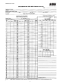
1
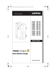
®
INSTALLATION
&
OPERATING
INSTRUCTIONS
SECTION 93.10 2014-08
YOUR GNB REPRESENTATIVE
SAlESPErSoN
TElEPhoNE
loCATIoN
GNB SERVICE ASSISTANCE
1-800-241-4895
Page
SECTION 1
1.0 General Information . . . . . . . . . . . . . . . . . . . .1
SECTION 2
2.0 Safety Precautions . . . . . . . . . . . . . . . . . . . .1
SECTION 3
3.0 receipt of Shipment . . . . . . . . . . . . . . . . . . .1
3.1 Concealed damage . . . . . . . . . . . . . . . . . . . .2
3.2 Electrolyte levels . . . . . . . . . . . . . . . . . . . . .2
SECTION 4
4.0 Storage Prior to Installation . . . . . . . . . . . . . .2
4.1 Storage location . . . . . . . . . . . . . . . . . . . . . .2
4.2 Parts and Accessories . . . . . . . . . . . . . . . . . .2
4.3 Storage Interval . . . . . . . . . . . . . . . . . . . . . . .2
4.4 dry Charged Batteries . . . . . . . . . . . . . . . . . .2
SECTION 5
5.0 rack Assembly . . . . . . . . . . . . . . . . . . . . . . .2
SECTION 6
6.0 Unpacking and handling . . . . . . . . . . . . . . . .2
SECTION 7
7.0 Installation . . . . . . . . . . . . . . . . . . . . . . . . . . .3
7.1 Battery location . . . . . . . . . . . . . . . . . . . . . . .3
7.2 Temperature . . . . . . . . . . . . . . . . . . . . . . . . . .3
7.3 Temperature variation . . . . . . . . . . . . . . . . . .3
7.4 ventilation . . . . . . . . . . . . . . . . . . . . . . . . . . .3
7.5 Placement of Cells . . . . . . . . . . . . . . . . . . . . .3
7.6 Connecting Cells . . . . . . . . . . . . . . . . . . . . . .4
7.7 Completing Installation . . . . . . . . . . . . . . . . .6
SECTION 8
8.0 Initial Charge . . . . . . . . . . . . . . . . . . . . . . . . .7
8.1 Constant voltage Method . . . . . . . . . . . . . . .7
8.2 Initial Charge-Electrolyte levels . . . . . . . . . .7
SECTION 9
9.0 operation . . . . . . . . . . . . . . . . . . . . . . . . . . . .7
9.1 Floating Charge Method . . . . . . . . . . . . . . . .7
9.2 Float Charge-Float voltages . . . . . . . . . . . . .7
9.3 voltmeter Calibration . . . . . . . . . . . . . . . . . . .8
9.4 Cycle Method of operation . . . . . . . . . . . . . .8
9.5 recharge . . . . . . . . . . . . . . . . . . . . . . . . . . . .8
SECTION 10
10.0 Equalizing Charge . . . . . . . . . . . . . . . . . . . . .8
10.1 Equalizing Frequency . . . . . . . . . . . . . . . . . .8
10.2 Equalizing Charge Method . . . . . . . . . . . . . .9
10.3 Equalizing Individual Cells . . . . . . . . . . . . . . .9
10.4 Equalizing Charge—Electrolyte levels . . . . .9
SECTION 11
11.0 Specific Gravity . . . . . . . . . . . . . . . . . . . . . . .9
11.1 hydrometer readings . . . . . . . . . . . . . . . . .10
11.2 Correction for Temperature . . . . . . . . . . . . .10
11.3 Correction for Electrolyte level . . . . . . . . . .10
11.4 Specific Gravity range . . . . . . . . . . . . . . . .10
INDEX
Page
SECTION 12
12.0 Cell voltage variation . . . . . . . . . . . . . . . . . .10
12.2 Cell voltage variation–damp Covers . . . . . .11
12.2 Cell voltage–Temperature Correction . . . . .11
12.3 Correction Factor . . . . . . . . . . . . . . . . . . . . .11
SECTION 13
13.0 Pilot Cell . . . . . . . . . . . . . . . . . . . . . . . . . . . .11
SECTION 14
14.0 records . . . . . . . . . . . . . . . . . . . . . . . . . . . .11
SECTION 15
15.0 Water Additions . . . . . . . . . . . . . . . . . . . . . .12
15.1 Water Purity . . . . . . . . . . . . . . . . . . . . . . . . .12
SECTION 16
16.0 Tap Connections . . . . . . . . . . . . . . . . . . . . .12
SECTION 17
17.0 Temporary Nonuse . . . . . . . . . . . . . . . . . . .12
SECTION 18
18.0 Battery Cleaning . . . . . . . . . . . . . . . . . . . . .12
18.1 Styrene Acrylonitrile Containers with
Butadiene Styrene Covers . . . . . . . . . . . . . .12
18.2 Polycarbonate Containers and Covers . . . .12
SECTION 19
19.0 Connections . . . . . . . . . . . . . . . . . . . . . . . . .13
19.1 Connection resistance . . . . . . . . . . . . . . . .13
19.2 retorquing Connections . . . . . . . . . . . . . . .13
19.3 Connection resistance Measurement . . . . .14
TABLES
TABLE A . . . . . . . . . . . . . . . . . . . . . . . . . . . . . . . . .7
TABLE B . . . . . . . . . . . . . . . . . . . . . . . . . . . . . . . . .7
TABLE C . . . . . . . . . . . . . . . . . . . . . . . . . . . . . . . .8
TABLE d . . . . . . . . . . . . . . . . . . . . . . . . . . . . . . . .9
TABLE E . . . . . . . . . . . . . . . . . . . . . . . . . . . . . . . . .9
STATIONARY BATTERY MAINTENANCE
REPORT . . . . . . . . . . . . . . . . . . . . . . . . . . . . . . .15
FIGURES
FIGURE
FIGURE
FIGURE
FIGURE
FIGURE
FIGURE
FIGURE
FIGURE
FIGURE
FIGURE
FIGURE
1 . . . . . . . . . . . . . . . . . . . . . . . . . . . . . . .2
2 . . . . . . . . . . . . . . . . . . . . . . . . . . . . . . .4
2A . . . . . . . . . . . . . . . . . . . . . . . . . . . . . .5
3 . . . . . . . . . . . . . . . . . . . . . . . . . . . . . . .6
4 . . . . . . . . . . . . . . . . . . . . . . . . . . . . . . .6
5 . . . . . . . . . . . . . . . . . . . . . . . . . . . . . .10
6 . . . . . . . . . . . . . . . . . . . . . . . . . . . . . .14
7 . . . . . . . . . . . . . . . . . . . . . . . . . . . . . .14
8 . . . . . . . . . . . . . . . . . . . . . . . . . . . . . .14
9 . . . . . . . . . . . . . . . . . . . . . . . . . . . . . .14
10 . . . . . . . . . . . . . . . . . . . . . . . . . . . . .14
d. When preparing electrolyte, always pour acid into water,
NEVER water into acid. Failure to follow this precaution
will result in excess heat and violent chemical reaction
which may cause serious injury to personnel.
SECTION 1
1.0
General Information
E. If electrolyte comes into contact with skin or clothing,
immediately wash with water and neutralize with a solution of baking soda and water. Secure medical treatment. If electrolyte comes into contact with the eyes,
wash or flush with plenty of clean water. Secure medical
treatment immediately.
Caution! Before proceeding with the unpacking, handling,
installation and operation of this lead-acid storage battery,
the following general information should be reviewed together with the recommended safety precautions.
A lead-acid battery is an electro-chemical device containing
electrolyte which is a dilute solution of sulfuric acid and
water. This electrolyte is corrosive and can cause injury.
F.
lead-acid batteries, when installed, are capable of high voltage which can cause electrical shocks to personnel.
All lead-acid batteries, in the course of normal operation,
generate gases which could be explosive.
G. Promptly neutralize and remove any electrolyte spilled
when handling or installing cells. Use a baking soda/water
solution (1 lb. per gallon of water) to prevent possible
injury to personnel.
Stationary batteries (when installed) are usually on float
charge continually, unless on discharge in the event of AC
failure, or on recharge following a discharge.
h. Make sure that all battery connections are properly prepared and tightened to prevent possible injury to personnel or failure of system.
SECTION 2
I.
BATTERY WARNING STATEMENT
DANGER
HIGH VOLTAGE
high voltages are present on most battery systems.
Exercise caution and rEMovE All METAl
oBJECTS FroM PErSoN when working on or
around battery.
J.
EXPLOSIVE GASES
Gases produced by battery can be explosive. do NoT
SMoKE, USE AN oPEN FlAME, CrEATE AN ArC
or SPArKS IN vICINITy oF BATTEry. WEAr EyE
ProTECTIoN.Personnel should discharge static
charges from their person to ground before working on
battery. ventilate well in an enclosed space and when
charging.
Whenever possible, when making repairs to charging
equipment and/or batteries, interrupt AC and dC circuits
to reduce the possibility of injury to personnel and damage to system equipment. This is particularly important
with high voltage systems (110 volts and above).
NOTE: If the foregoing precautions are not fully understood,
clarification should be obtained from your nearest GNB representative. local conditions may introduce situations not
covered by GNB Safety Precautions. here again, contact
the nearest GNB representative for guidance with your particular safety problem; also refer to applicable federal, state,
and local regulations as well as industry standards.
Safety Precautions
A. Wear rubber apron, gloves and safety goggles (or face
shield) when handling, installing, or working with batteries. This will help prevent injury due to splashing or
spillage of sulfuric acid.
B. Prohibit smoking. Keep flames and sparks of all kinds away
from vicinity of storage batteries as liberated or entrapped
hydrogen gas in the cells may be exploded,causing injury to
personnel and damage to cells.
C. Never place metal tools on top of cells, since sparks due to
shorting across cell terminals may result in an explosion of
hydrogen gas in or near the cells. Insulate tool handles to
protect against shorting.
Familiarize personnel with battery installation, charging
and maintenance procedures. restrict access to battery
area, permitting trained personnel only, to reduce the
possibility of injury.
K. When maintaining a connected battery string, care must
be taken to prevent a build-up of static charge. This
danger is particularly significant when the worker is electrically isolated, ie. working on a rubber mat or an epoxy
painted floor or wearing rubber shoes. Prior to making
contact with the cell, discharge static electricity by touching a grounded surface. Wearing a ground strap while
working on a connected battery string is not recommended.
ACID BURNS
Battery contains SUlFUrIC ACId WhICh CAN
CAUSE SEvErE BUrNS. Avoid getting in eyes, on
skin, or on clothing. In case of contact, flush immediately and thoroughly with clean water. oBTAIN MEdICAl
ATTENTIoN.
2.0
Exercise care when handling cells. When lifting straps
and strap spreaders are provided, use them with appropriate mechanical equipment to safely handle cells and
avoid injury to personnel.
SECTION 3
3.0
Receipt of Shipment
Immediately upon delivery by the carrier, examine for possible damage caused in transit. damaged packing material or
staining from leaking electrolyte would indicate rough handling.
1
If such conditions are found, make description notation on
delivery receipt before signing. If cell damage is found, request
an inspection by the carrier and file a damage claim. Also notify local GNB representative of action taken.
Storage beyond the above stated periods can result in sulphated plates which can be detrimental to battery life and
performance.
The battery should be given its initial charge (see Section
8.0) before the end of the above stated storage intervals and
repeated for each additional storage interval.
3.1 Concealed Damage
If permanent installation is deferred for an extended time
period, the battery may be temporarily connected and maintained on a floating charge (see Section 9).
Shortly after receipt (within 15 days), examine all cells for concealed damage. Pay particular attention to packing material
exhibiting damage or electrolyte staining. Perform examination
prior to installation and disposal of packing materials. Cells with
electrolyte levels more that 1/2" below top of plates have suffered probable permanent damage due to plate exposure to air.
If this condition or other cell damage is found, request an inspection by the carrier immediately and file a concealed damage
claim. Examine cells for container damage, misaligned elements, broken plates, or any other visible damage.
Failure to charge in accordance with the above can void the
battery's warranty.
4.4 Dry-Charged Batteries
For batteries shipped dry-charged, follow special handling
and preparation instructions supplied as well as appropriate
sections of this Manual.
3.2 Electrolyte Levels
Cells are shipped with electrolyte levels about 1/8" below the
high level line. during shipment, the levels drop due to the loss
of gases from internal cell components. The amount of drop in
level will vary with each type of cell. Electrolyte levels, when
received, may range from the high level line to slightly below the
low level line. If this condition exists, make no addition of electrolyte or water at this time (see Section 8.2). If certain cells
have low electrolyte levels, with less than 1/2" of plates exposed
to air, add battery grade sulphuric acid of the same specific gravity as the remaining cells; thus bringing low level cells up to the
average level of other cells.
SECTION 5
5.0 Rack Assembly
Assembly of the battery rack should be completed in accordance with the GNB drawing and/or instructions included
with the rack.
SECTION 6
6.0 Unpacking and Handling
Most cells are packed in individual corrugated cartons.
Some smaller size cells are packed in a master carton containing 2 (two) or 3 (three) cells. Cartons are shipped on
wood pallets.
SECTION 4
4.0 Storage Prior to Installation
4.1 Storage Location
If the battery is not to be installed at the time of the receipt, it is
recommended that it be stored indoors in a cool, 60°F (15.6° C)
to 90° F (32° C), clean, dry location. do not top load pallets or
possible cell damage may occur. Storage or transport of flooded lead-acid batteries at temperatures exceeding 120°F (49°C)
can cause detimental effects on plastic components and battery
state of health which may void warranty.
4.2 Parts and Accessories
Prior to planned installation of battery, the separately packaged
parts and accessories should be opened and checked against
shipping invoice for completeness. discovery of missing or
incorrect parts during installation may cause delays resulting
from reordering and shipment of replacements. Store parts in
safe location to prevent loss.
4.3 Storage Interval
For batteries shipped wet, fully-charged, the following storage
intervals from date of shipment to date of installation and initial
charge should not be exceeded:
lead-Antimony Types:
Three (3) Months
lead Calcium Types:
Six (6) Months
2
Figure 1
remove material holding cartons to pallets, exercising care
when cutting banding material to prevent injury. If individual
cells are to be moved to another location, do not remove
carton at this time. Exercise caution if using a two-wheeled
hand truck and, to prevent spillage of electrolyte, do not tilt
cell more than 25 degrees from vertical. When cells have
been brought to the installation sight, remove carton sleeve
and top corrugated spacers.
7.3 Temperature Variation
The location of rack arrangement should result in no greater
than 5°F (2.78°C) variation in cell temperatures in a series
string at any given time. If a greater variation is found, steps
should be taken to correct the condition. When uniform cell
temperature is maintained, the need for equalizing charges
may be eliminated or reduced in frequency.
do NoT lIFT CEllS By ThEIr TErMINAl PoSTS.
Support the cells from the bottom when handling and
unpacking. In general, units weighing less than 75 pounds
are handled manually, being supported from the bottom.
7.4 Ventilation
In the operation of lead-acid battery whether it be on initial
charge, float charge, equalizing charge or recharge following a discharge, hydrogen and oxygen gases are produced.
This results from electrolysis of the water portion of the electrolyte by the charging current.
After removal of outer carton and top spacers, the cell should still
be resting in the bottom corrugated tray. This tray is designed to
be easily broken away to permit positioning of a lifting strap
under the cell with a minimal amount of cell tilting.
ventilation should be provided in the battery room or area to
prevent hydrogen, liberated from the cells in service, from
exceeding a 1% concentration. Concentrations above this
percentage can result in an explosive mixture, which could
be ignited by sparks from adjacent electrical equipment as
well as accidental sparks or open flames introduced by personnel. All air moved by ventilation in the battery room or
area should be exhausted into the outside atmosphere and
should not be allowed to recirculate into other confined
areas.
A lifting strap and a strap spreader are furnished for use with
mechanical lifting devices, when cells weigh 75 pounds or
more. See Figure 1 which shows typical positioning of strap
and spreader. large cells are provided with 2 lifting straps
and a special spreader for stability in handling during installation.
Always use lifting straps and spreaders, when provided,
together with suitable mechanical lifting devices to prevent
injury to personnel or damage to cells.
7.5 Placement of Cells
It is assumed at this point that the battery rack has been
assembled. Study the rack layout and wiring drawings to
determine proper location of the positive and negative terminals of the battery; this will establish correct positioning of
the initial cell on each rack row. Cells are normally installed
with plate edges perpendicular to rack length.
Platform lifts of adequate capacity to handle cell weights and
dimensions may be used provided they are stable and capable of reaching needed heights and used on smooth and
level floor conditions.
Never slide cells across rough surfaces as severe scratching of plastic container bottom may result in stressing and
rupturing of the jar with subsequent loss of electrolyte. At all
times, exercise care when handling cells to prevent scratching of plastic jars and covers.
Measure and mark the center of the rack stringer length.
determine the number of cells to be placed in each row.
When an odd number of cells are in the row, place the center of the initial cell at the center point of the rack stringer
length.
SECTION 7
When an even number of cells are in the row, locate the initial cells so that the center of the space between the cells
coincides with the center mark of the stringer length.
7.0 Installation
7.1 Battery Location
To reduce friction and facilitate the sliding of cells from platform lift into position on the battery rack, only dow Corning
#111 silicone grease is permitted for use.
It is recommended that the battery be installed in a clean,
cool, dry location. Cells should not be exposed to heating
units, strip heaters, radiators, steam pipes or sunshine
through a window. Any of these conditions can cause a serious electrolyte temperature variation among cells within a
battery (see Section 7.3).
USE OF LUBRICANTS OTHER THAN
DOW CORNING #111 SILICONE GREASE
WILL VOID WARRANTY.
7.2 Temperature
A battery location having an ambient temperature of 75°F
(24°C) to 77°F (25°C) will result in optimum battery life.
Batteries operated in high ambient temperatures will result
in reduced life. Therefore, for longer life and ease of maintenance, locations having cooler ambient temperatures are
recommended. The normal battery operating temperatures
are between 60°F (16°C) and 90°F (32°C).
DO NOT USE METAL RODS, SCREWDRIVERS, ETC. THROUGH POST HOLES
TO POSITION CELLS AS THIS PRACTICE
CAN CAUSE SHORTING AND POST
DAMAGE AND WILL ALSO VOID WARRANTY.
3
When installing cells on the rack, start at the lower step or
tier for stability and safety reasons.
on cells using stainless steel bolts, washers and nuts, make
sure a washer is placed between the bolt head and connector as well as between the nut and connector with the rolled
edge against the connector. Never install washers between
the connector and the cell post. (See figure 2A).
Place cells on the rack so that the positive terminal (marked
“+”) of each cell adjoins the negative terminal (marked “-”) of
the next cell. The standard spacing between cells is 1/2” at
the top of the jars.
Adjacent cells should not touch; nor should any cell contact
the metal rack supports or metal cable conduits. Check for
proper alignment and 1/2” spacing between cells. Adjust
cell position where necessary. This should be completed
before installation of intercell connectors.
CAUTION!
WhEN INSTAllING TErMINAl hArdWArE
do NoT PErMIT ANy ITEMS To FAll INTo
CEll. IF SUCh MATErIAl rEMAINS IN ThE
CEll, CoNTAMINATIoN WIll rESUlT,
rEQUIrING rEPlACEMENT oF ThE CEll.
Use two 1/2” thick pieces of plywood cut to cell width and 1”
higher than jar height to expedite positioning of cells. Space
cells by placing one piece between the first cell positioned
and the next cell. In positioning the third cell, use the second piece of plywood for spacing. The first piece is
removed and used for the next cell placement, etc.
As intercell connectors are installed, adjust them to a level
position and finger tighten hardware.
After all connectors are installed, the hardware should be
tightened using insulated tools as outlined in the following
illustration. (Figure 2):
The cell post surfaces have a coating of No-oX-Id grease
or approved equal applied at the factory. do not remove any
grease from posts. re-coat any surfaces that may have
been exposed during handling of cells.
Also closely examine factory coated post contact surfaces
for presence of foreign substances which may have been
introduced through handling or construction activity in the
installation area. If the foregoing is noted, remove the NooX-Id grease or approved equal with paper wipers and
apply a new coating. Also inspect posts for corrosion. If
corrosion is found, clean posts with brass suede brush or
plastic scouring pad and re-grease.
QUANTITy ANd ThICKNESS
oF INTErCEll CoNNECTorS
1/8” or 1/4”
1/8”
FAIlUrE To oBSErvE ABovE ProCEdUrE
MAy IMPAIr INTEGrITy oF ElECTrICAl
CoNNECTIoN ANd CEll PErForMANCE.
Figure 2
100
(M & N cells)
150
1/4” (PdQ, N & h cells) 150
Torque both the bolt head and the nut of stainless steel
hardware to their prescribed torque values. Torquing only
one side of either combination will not provide the desired
tightness.
7.6 Connecting Cells
re-torque stainless steel hardware 4 to 6 hours after initial
torquing to allow for initial relaxation of connection components.
refer to the cell arrangement drawing to determine the
quantity, size, and correct positioning of the intercell connectors. on the “N” type cells using 1 1/4” wide connectors,
the bolt holes are located off-center. Position the connector
so that the lesser dimension faces downward on the cell
post.
Complete connecting of cells by installing necessary interrow, inter-tier or inter-rack cable connectors. do not connect battery to charger at this time.
Gently clean contact surfaces only of the lead plated intercell connectors, terminal plates and cable lugs using a brass
suede brush or 3M Scotch Brite scouring pad. Caution: do
not use powered wire brush or course abrasives, as lead
plating may be removed exposing copper.
Take and record connection resistances (See Section 19.0)
of cell to cell and cell to terminal (including inter level and
load connections). This is particularly important on high rate
applications. remake any connection that has a value more
than 10% or 5 u Ω, whichever is greater.
As contact surfaces of posts and connectors are cleaned,
apply a thin coating of No-oX-Id grease or approved equal
to these surfaces only.
Starting at center of the cell row, install connectors per
wiring diagram and cell arrangement drawing furnished with
the battery.
(d cells only)
(M & N cells) 100
1/4” or two 1/8”
CAUTION!
TorQUE (INCh lBS).
re-check to be certain that the cells are connected positive
(+) to negative (-) throughout the battery string. Measure
the total voltage at the battery terminals. The voltage should
be equal to the number of cells times the voltage of one of
the cells. Example: 60 cells times 2.05 volts = 123 volts.
4
5
dUST CAPS
ElECTrolyTE
WIThdrAWAl
Figure 3
7.7
Figure 4
Electrolyte Withdrawal Tubes
Certain calcium cells are equipped with two electrolyte withdrawal tubes which are installed in the diagonal corners of
the cell. These permit the taking of specific gravity readings
at a point about one-third from the top of the plates. (See
Section 11.1). refer to Figure 3.
Completing Installation
Explosion resistant vents
Certain cell sizes may have been shipped with GNB Prevent™ vent/filling funnels in place. These vents have flexible plastic caps installed for shipping purposes. These caps
may be removed and discarded, or they may be left in place
if the battery environment is dusty. (See Figure 3)
A flexible shipping cap and shipping plug is installed on each
withdrawal tube. The cap may be removed and discarded
after neutralizing or left in place as dust covers. The red plug
should be discarded.
other cell sizes are supplied with Pre-vents which are not
shipped in place. A standard screw-type vent is used for shipping purposes. If Pre-vent units were specified, they would
have been packed separately with other accessories. remove
the screw-type shipping vents one-at-a-time and install a Prevent unit before charging. discard the shipping vent.
Plastic Numerals (See Page 16)
Plastic cell numerals and battery terminal polarity labels are
provided for 12-cell batteries of 40 ampere hours and over.
The positive terminal cell is usually designated as cell #1 in
the series string.
other cell types are supplied with separate explosion resistant vents installed at time of shipment. Separate plastic filling funnels are supplied along with this type vent. These
funnels also have flexible plastic shipping caps. here again,
these may be removed and discarded or left in place if environment is dusty.
Battery-to-Charger Connection
The positive (+) terminal of the battery should be connected
to the positive (+) terminal of the charger and the negative
(-) terminal of the battery to the negative (-) terminal of the
charger.
The Pre-vent assembly and other explosion resistant vents
are designed to prevent external sparks or flames from igniting and exploding internal cell gases. (See Figure 4).
Battery Warning Statement and Nameplate (See Page 1)
CAUTION!
BEForE dISPoSING oF FlEXIBlE PlASTIC
CAPS or SCrEW-TyPE ShIPPING CAPS,
NEUTrAlIZE ANy ElECTrolyTE oN ThEM
IN A BAKING SodA - WATEr SolUTIoN To
PrEvENT INJUry To ANyoNE hANdlING
ThESE dISCArdEd ITEMS.
6
A nameplate is shipped with the parts for each battery system. It has a peel-off backing to allow mounting on or near
the battery. Nameplate information should be completed by
the installer at the time of the initial charge and start of battery operation. The installer must make the contents of the
Battery Warning Statement known to all personnel in the
vicinity of the battery.
TABLE B
SECTION 8
8.0
Initial Charge
Batteries lose some charge during shipment as well as during
the storage period prior to installation. The battery should be
installed and given its initial charge as soon after receipt as
possible. At the completion of initial charge, record voltage
and specific gravity of each cell while still on charge and retain
records for future reference per Section 14.0.
8.1
Cell volts
2.24
2.27
2.30
2.33
2.36
2.39
2.42
2.45
2.48
2.50
Constant Voltage Method
Constant voltage is the principal method to give the initial
charge, as most modern chargers are of the constant voltage design. In addition, some systems have equipment with
voltage limitations making the use of constant current charging undesirable.
determine the maximum voltage that may be applied to the
system equipment. The voltage divided by the number of
cells connected in series will establish the maximum voltage
per cell that may be used.
8.2
For lead-antimony types, refer to Table A and for lead-calcium types refer to Table B to obtain various voltages and
associated time periods recommended. Select the highest
voltage the system will allow, to perform the initial charge in
the shortest period of time.
—
—
—
—
400
267
182
125
83
60
Initial Charge — Electrolyte Levels
SECTION 9
INITIAL CHARGE
recommended voltages and Time Periods
9.0
Operation
9.1
Floating Charge Method
9.2
Float Charge — Float Voltages
In this type of operation, the battery is connected in parallel
with a constant voltage charger and the critical load circuits.
The charger should be capable of maintaining the required
constant voltage at battery terminals and also supply a normal connected load were applicable. This will then sustain
the battery in a fully charged condition and also make it
available to assume the emergency power requirements, in
the event of an AC power interruption or charger failure.
TABLE A
lead-Antimony Types
NOTE: Time Periods listed in tables A and B are for cell
Time-hrs
1.250
sp. gr.
—
—
—
146
129
97
73
54
36
30
temperatures from 70°F (21°C) to 90°F (32°C). For temperatures 55°F (13°C) to 69°F (20.5°C) double the number of
hours. For temperatures 40°F (4°C) to 54°F (12°C) use four
times the number of hours.
—
—
—
333
235
160
108
73
55
44
Time-hrs.
1.300
sp. gr.
removal of electrolyte during the initial charge with subsequent restoration with water of levels which have fallen following placement on float charge mode could result in variations or sub-normal specific gravity values.
The recommended time periods are considered minimum.
raise the voltage to the maximum value permitted by the
system equipment. When charging current has tapered and
stabilized (no further reduction for 3 hours), charge for the
hours shown in the appropriate table and for the battery
temperature, at the time of stabilization, until the lowest cell
voltage ceases to rise. Monitoring of cell voltages should be
started during the latter 10% of the applicable time period to
determine lowest cell in battery.
Cell volts
2.24
2.27
2.30
2.33
2.36
2.39
2.42
2.45
2.49
2.50
444
333
210
148
100
67
48
38
36
32
Time-hrs.
1.250
sp. gr.
during the initial charge, there will be an increase in the
electrolyte levels and they may go above the high level
mark. (See Section 3.2). This is due to gases, that were lost
during transportation or standing in storage, being restored
to the cells. do not remove any electrolyte even though levels may be above high level. When battery is placed on
floating charge (See Section 9.2). the electrolyte levels
should return close to the high level line.
Establish whether the battery is of lead-antimony or leadcalcium construction by referring to type on cell name plate
and compare this with the proper GNB sales literature.
Time-hrs.
1.215
sp. gr.
200
150
120
90
75
60
—
—
—
—
lead-Calcium Types
Time-hrs.
1.215
sp. gr.
The following are the float voltage ranges recommended for
the various types of batteries. Select any “volts per cell”
value within the range listed that will result in the series
string having an average volts per cell equal to that value.
do not interchange voltage ranges from one type to another.
7
When the cell voltage reaches 2.33, the charge rate should
be reduced to the normal finish charge rate. The finish
charge rate is defined as amperes equal in numerical value
to 5% of the cell’s 8-hour capacity in ampere hours. For
example, if the cell has an 8-hour capacity of 1680 Ah, its
finish rate is 84 amperes. The charge should be stopped
when the specific gravity is ten (.010) points below the normal fully charged value.
TABLE C
recommended Float voltages
Lead-Antimony Types:
Nominal 1.215 sp. gr.
Nominal 1.250 sp. gr.
Lead Calcium Types:
Nominal 1.215 sp. gr.
Nominal 1.250 sp. gr.
Nominal 1.300 sp. gr.
2.15 to 2.17 vPC
2.19 to 2.23 vPC
2.17 to 2.25 vPC
2.23 to 2.33 vPC
2.28 to 2.37 vPC
The battery is now available for the next discharge requirement. The battery should be given an equalizing charge
monthly by continuing the regular charge until there is no
increase in specific gravity of the pilot cell for three hours.
when using the finish charge rate.
Modern constant voltage output charging equipment is recommended for the floating charger method of operation of
GNB stationary type batteries. This type of charger, properly adjusted to the recommended float voltages, together with
adherence to recommended maintenance procedures, will
assist in obtaining consistent serviceability and optimum life.
9.5
All batteries should be recharged as soon as possible following a discharge (within 8 hours). With constant voltage
chargers, this will be accomplished automatically. however,
to recharge in the shortest period of time, raise the charger
output voltage to the highest value which the connected system will permit. do not exceed those voltage values listed
in Table d or Table E on page 9.
After the battery has been given its initial charge (see
Section 8.0), the charger should be adjusted to provide the
recommended float voltage (see Table C) at the battery terminals. For example, a 60-cell lead antimony battery should
have 130 volts maintained at its terminals. . . 60 cells x 2.17
volts per cell (v.P.C.) = 130 volts.
do not use voltages for lead-antimony types higher than
shown in table C, as excessive water consumption and
reduced battery life will result.
SECTION 10
lead-calcium types may be floated at any of the voltage values (Table C) shown for a particular nominal specific gravity. Use the lower vPC value in the appropriate nominal specific gravity group, where system equipment voltage limitations will not permit higher values. The use of higher vPC
values may make it unnecessary to give an equalizing
charge. however, the use of higher float voltages where
high ambient temperatures prevail may result in reduced
battery life.
9.3
10.0 Equalizing Charge
An equalizing charge is a special charge given a battery
when non-uniformity in voltage or specific gravity has developed between cells. It is given to restore all cells to a fully
charged condition using a charging voltage higher than the
normal float voltage and for a specified number of hours, as
determined by the voltage used.
Non-uniformity of cells may result from low floating voltage
due to improper adjustment of the charger or a panel voltmeter which reads incorrect (higher) output voltage. Also,
variations in cell temperatures greater than 5°F (2.78°C) in
the series string at a given time, due to environmental conditions or rack arrangement, can cause low cells.
Voltmeter Calibration
Panel and portable voltmeters used to indicate battery float
voltages should be accurate at the operating voltage value.
The same holds true for portable meters used to read individual cell voltages. These meters should be checked
against a standard every six months and calibrated when
necessary.
9.4
Recharge
10.1 Equalizing Frequency
The following guidelines cover lead-antimony and leadcalcium types. recommendations not applying to all types
will be so designated.
A.
Cycle Method of Operation
This method is recommended for lead antimony type cells
only. lead-calcium cells should not be cycle operated.
In cycle operation, the degree of discharge will vary for various applications. Therefore, the frequency of recharging
will also vary. The recharge is conducted by manually starting the charge, generally using the normal finish rate. The
amount of charge necessary depends on the number of
ampere hours discharge. If a shorter recharge period is
desired, higher charge rates equal to the eight-hour rate of
discharge may be used when the battery is more than 25%
discharged and the cell voltage on charge is below 2.33
volts.
An equalizing charge should be given quarterly or as
required by conditions in the following paragraphs (Note:
lead-calcium types at nominal 1.215 sp. gr. floated 2.20
v.P.C., to 2.25 v.P.C., nominal 1.250 sp. gr. floated at 2.27
v.P.C. to 2.33 v.P.C. and nominal 1.300 sp. gr. floated at
2.31 v.P.C. to 2.37 v.P.C. may not require equalizing charges).
B. Equalize when the temperature corrected specific gravity of the pilot cell (or any cell for the quarterly reading)
is more than 10 points below its full charge value. (See
Section 11.2)
8
C. Equalize when the floating voltage of the pilot cell (or
any cell for the quarterly reading) is below 2.13 volts
(nominal 1.215 sp. gr.), 2.18 volts (nominal 1.250 sp.
gr.) and 2.23 volts (nominal 1.300 sp. gr.) or more than
.04 volts below the average for the battery.
d. Equalize to complete a recharge of the battery in a minimum length of time following an emergency discharge.
NOTE: Time periods listed in Tables d and E are for cell
temperatures from 70°F (21°C) to 90°F (32°C). For temperatures 55°F (13°C) to 69°F (20.5°C) double the number of
hours. For temperatures 40°F (4°C) to 54°F (12°C) use four
times the number of hours.
E. If accurate quarterly records are maintained (See
Section 14.0) and the individual cell voltages and teperature corrected specific gravities show no increase
instead from the previous quarterly readings, equalizing
may be deferred. (See Section 11.2)
F.
10.3 Equalizing Individual Cells
When only a few cells in a battery require equalizing, and
system voltage limitations do not permit raising the battery
voltage up to a recommended equalizing voltage, a separate voltage regulated charger may be used on the affected
cells.
Equalize once a year even though preceding conditions
did not require. (lead-calcium types floated per paragraph A, may not require annual equalizing).
10.2 Equalizing Charge Method
Constant voltage charging is the preferred method for giving
an equalizing charge. determine the maximum voltage that
may be applied to system equipment. This voltage, divided
by the number of cells connected in series, will establish the
maximum voltage per cell that may be used to perform the
equalizing charge in the shortest period of time.
The charger must have complete AC line isolation and
should be paralleled across the below normal cell. Select
the equalizing voltage values listed in Tables d or E for the
type cell involved. The hours of equalizing may have to be
increased from listed values before stabilization of cell voltage and specific gravity is achieved, especially where below
normal condition has existed for a prolonged period.
For lead-antimony types, refer to Table d and for lead-calcium type, refer to Table E to obtain various voltage and associated time period recommended.
CAUTION!
The recommended time periods below are considered minimum. raise the voltage to the maximum value permitted by
the system equipment. When charging current has tapered
and stabilized (no further reduction for three hours), charge
for the hours shown in the appropriate table and for the battery temperature, at the time of stabilization, until the lowest
cell voltage ceases to rise. Monitoring of cell voltages
should be started during the latter 10% of the applicable
time period to determine the lowest cell in battery.
WhEN INdIvIdUAl ChArGEr IS rEMovEd
FroM CEll WhICh hAS BEEN EQUAlIZEd,
A droP IN volTAGE BEloW ThE AvErAGE
STrING volTAGE MAy oCCUr. ThIS IS
NorMAl, dUE To ThE EXCESS INTErNAl
CEll GASES PrESENT. AS ThESE EXCESS
GASES dISlodGE FroM INTErNAl CEll
CoMPoNENTS, ThE CEll volTAGE WIll
rISE GrAdUAlly, WhICh MAy TAKE FroM
TWo To FoUr WEEKS.
EQUALIZING CHARGE
recommended voltages and Time Periods
TABLE D
lead-Antimony Types
Cell volts
2.24
2.27
2.30
2.33
2.36
2.39
2.42
2.45
2.48
Cell volts
2.24
2.27
2.30
2.33
2.36
2.39
2.42
2.45
2.48
Time-hrs.
1.215
sp. gr.
80
60
48
36
30
24
—
—
—
TABLE E
lead-Calcium Types
Time-hrs.
1.215
sp. gr.
222
166
105
74
50
34
—
—
—
Time-hrs.
1.250
sp. gr.
—
—
—
166
118
80
54
36
—
Time-hrs.
1.250
sp. gr.
—
—
—
58
51
39
29
26
24
Time-hr.s
1.300
sp. gr.
—
—
—
—
200
134
91
62
42
10.4 Equalizing Charge—Electrolyte
Levels
A battery which has electrolyte levels at the high level line
while on a float and then placed on equalizing charge will
result in a rise in electrolyte above the high level line. This
is a normal condition. do NoT remove any electrolyte as
the levels will return to their former condition when the battery is returned to normal float. removal of the electrolyte
with subsequent restoration to proper electrolyte levels by
water addition could result in variations or sub-normal specific gravity values.
SECTION 11
11.0 Specific Gravity
9
In a lead-acid cell, the electrolyte is a dilute solution of water
and sulfuric acid. Specific gravity is a measure of the weight
of acid in the electrolyte as compared to an equal volume of
water. Therefore, electrolyte with a specific gravity of 1.215
means it is 1.215 times heavier than an equal volume of
water which has a specific gravity of 1.000.
11.1 Hydrometer Readings
Specific gravity is used in determining a cell’s state of
charge. It decreases as the cell discharges and increases
as the cell is charged; reaching its original value when the
cell is fully charged. Specific gravity is expressed to the
third decimal place (1.215) and is measured by a hydrometer float enclosed in a glass barrel/rubber bulb syringe.
draw sufficient electrolyte into the barrels holding the
syringe vertical and with no hand pressure on bulb; so that
float is freely floating without touching sides or top of
syringe.
The gravity is read on the hydrometer scale at the flat surface of the electrolyte. (See Figure 5).
When taking a hydrometer reading, the base of the hydrometer syringe should be pressed firmly against the tube
opening to prevent back splash of electrolyte. Fill and
empty the hydrometer at least once in each cell before reading. This will give a more accurate reading of the average
electrolyte density.
Never inter-mix usage of hydrometers on lead-antimony or
lead-calcium types as cell contamination will result. Assign
hydrometers for exclusive use on one type only.
11.2 Correction for Temperature
When taking specific gravity readings, corrections must be
made for variations in temperature of the electrolyte. For
each 3°F (1.67°C) in temperature of the electrolyte above
77°F (25°C) add one point (.001) in specific gravity to the
observed hydrometer readings; and for each 3°F (1.67°C) in
temperature below 77°F (25°C) subtract one (.001) in specific gravity from the observed hydrometer reading.
Example:
hydrometer
reading
1.213 sp. gr
1.207 sp. gr.
1.204 sp. gr.
Cell
Temperature
68°F (20°C)
86°F (30°C)
95°F (35°C)
Correction
-.003 points=
+.003 points=
+.006 points=
reading
Corrected to
77°F (25°C)
1.210 sp. gr.
1.210 sp. gr.
1.210 sp. gr.
11.3 Correction for Electrolyte Level
Figure 5
Clean the hydrometer glass barrel and float with soap and
water as required for ease of reading and float accuracy.
When recharging a lead-calcium cell, the specific gravity
reading lags behind the ampere hour input due mainly to the
very low end of charge currents. Mixing of the electrolyte is
slow due to the small amount of gas generated; so the gravity readings do not reflect the actual state of charge. A similar condition exists after water additions. Therefore, meaningful gravity readings can only be obtained at the top of the
cell after an equalizing charge or after six weeks on float.
The loss of water from the electrolyte due to evaporation as
well as conversion of the water to hydrogen and oxygen by
charging current also effects the specific gravity value. For
example: A fully charged cell with a correct high level at
77°F (25°C) will have a nominal specific gravity of 1.215.
When the electrolyte level has been reduced from evaporation and charging by 1/4”, the specific gravity will be approximately 6 points (.006) higher or 1.221@ 77°F (25°C).
Therefore when taking hydrometer readings, the electrolyte
level referenced to the high level line should be recorded for
proper evaluation of the specific gravity value. This applies
when taking a pilot cell reading or for 10% of the cells when
taking a quarterly set of readings.
11.4 Specific Gravity Range
GNB stationary batteries are furnished with a nominal fully
charged specific gravity of 1.215@ 77°F (25°C).
For special applications, nominal specific gravity such as
1.250 or 1.300 @ 77°F (25°C) may be used.
The specific gravity may range± .010 points within a battery
for any of the nominal values @ 77°F (25°C) with the electrolyte level at the high level line and still be considered satisfactory.
SECTION 12
For this reason, most GNB lead-calcium cells have elec12.0 Cell Voltage Variation
trolyte withdrawal tubes to permit sampling of the electrolyte
at a point one third down from the top of the plates. A long
The tabulation on the following page indicates the normal cell
rubber tip on the hydrometer is inserted into the tube to provoltage variation that may exist with the battery on float and
vide an average value of cell specific gravity and a more
no greater than a 5°F (2.78°C) variation in cell temperature.
accurate indication on the state of the charge.
10
NORMAL VOLTAGE RANGE
Type
Lead-Antimony
Nominal 1.215 sp. gr.
Nominal 1.250 sp. gr.
Lead-Calcium
Nominal 1.215 sp. gr.
Nominal 1.250 sp. gr.
Nominal 1.300 sp. gr.
Average
Float voltage
A slight amount of electrolyte may be lost each time a specific
gravity reading is taken, even though it is recommended that all
electrolyte in the hydrometer be returned to the cell after reading. Therefore it is suggested that the pilot cell be changed to
another cell annually to provide a representative specific gravity
indicator for the battery.
variation
2.15 to 2.17 v.P.C.
2.19 to 2.23 v.P.C.
± .04 v.P.C.
± .04 v.P.C.
2.17 to 2.25 v.P.C.
2.23 to 2.33 v.P.C.
2.28 to 2.37 v.P.C.
± .05 v.P.C.
± .05 v.P.C.
± .05 v.P.C.
SECTION 14
14.0 Records
A complete recorded history of the battery operation is
required. Good records will also show when corrective
action may be required to eliminate possible charging, maintenance or environmental problems.
12.1 Cell Voltage Variation
Damp Covers
Cell voltage variation can also be the result of damp cell cover
tops. Spilled electrolyte when taking hydrometer readings can
result in parasitic currents paths across the tops of cell covers.
This reduces the float current through the cell resulting in voltage variations. See Section 18.0 - Battery Cleaning —to correct
damp cover condition.
data should be recorded on Stationary Battery Maintenance
report shown on page 15. report headings should be filled
in completely on the date of installation.
The following data should be read and permanently recorded for review by supervisory personnel.
12.2 Cell Voltage Temperature Correction
A. Upon completion of the initial charge and with the battery
floating at the desired float voltage for one week, read
and record individual cell voltages, connection resistances, specific gravities [corrected to 77°F (25°C)],
ambient temperature plus cell temperatures and electrolyte levels for 10% of the cells. The cell temperature
readings should be from each step or tier of the rack to
reflect temperature range of the battery.
To properly analyze cell uniformity within the string, cell voltages
should be corrected for cell electrolyte temperature. Cell voltage
variation that may have developed since a previous quarterly set
of readings may be due to cell temperature variations within the
string that may have resulted from a change in ambient conditions. Therefore, correcting cell voltage for cell temperature may
make it unnecessary to apply an equalizing charge which otherwise had been believed necessary. See Section 10.1 Equalizing Frequency.
This first set of readings will be the basis for comparison
with subsequent readings to reflect possible operating
problems and the need for corrective action.
12.3 Correction Factor
B. Monthly - observe the general appearance and cleanliness of the battery. record battery terminal voltage.
Check electrolyte levels and adjust if necessary. Check
for cracks in cells and leakage. Note any evidence of
corrosion at terminals and connectors. record pilot cell
voltage, specific gravity and temperature.
The temperature correction factor for cell voltage equals 0.003
volts for each degree fahrenheit (0.0055v/C°) using a base 77°F
(25°C). The correction is added to the measured cell voltage
above 77°F (25°C) and subtracted below 77°F (25°C).
Example: Measured cell voltage = 2.19v @ 87°F(30.5°C) cell
temperature. Correction = 10°F x .003v (3.5°C x .0055v) =
.03v. Therefore, corrected cell voltage = 2.19v + .03v = 2.22
volts.
C. Quarterly - Supplement the monthly inspection and
record keeping with these additional measures. Check
and record the specific gravity and voltage of each cell.
Check and record the electrolyte temperature of one cell
on each level of individual racks.
If the cell temperature in the example had been 67°F (19°C), the
correction would be .03 volts which is subtracted from the measured voltage of 2.19v. The corrected cell voltage = 2.19v .03v = 2.16v.
d. Annual - Supplement quarterly reports with these extra
procedures. Make a detailed visual inspection of each
cell. Tighten all bolted connections to the specified
torque values. Take and record connection resistances
of each cell to cell, cell to terminal, inter-level and load
connections. remake any connections that are more
than 20% above installation base value. Check integrity
of the rack.
SECTION 13
13.0 Pilot Cell
A pilot cell is selected in the series string to reflect the general condition of all cells in the battery regarding specific
gravities, float voltage and temperature. It serves as an indicator of battery condition between scheduled overall individual cell readings.
E. Any time the battery is given an equalizing charge (see
Section 10.1), an additional set of individual cell readings
11
should be taken after battery has been returned to normal
float for one week. These will serve as an updated basis for
comparison with future readings.
F.
SECTION 16
16.0 Tap Connections
It is not recommended that tap connections be used on a
battery, as possible unbalance between groups of cells may
result. This can cause overcharging of the untapped group
of cells and undercharging of the tapped cells supplying the
load. This condition can cause unsatisfactory operation and
reduced battery life.
record dates of any equalizing charges as well as total
quantity of water when added. Also record any maintenance and/or testing performed.
The foregoing frequency of record taking may have to
be modified somewhat to suit local requirements.
SECTION 17
See Page 16 for Battery nameplate
17.0 Temporary Nonuse
SECTION 15
An installed battery that is permitted to stand idle for a period of time should be treated in the following manner. With
the battery on normal float, add approved water to cells to
bring electrolyte level to the high level line. Give the battery
an equalizing charge per Section 10.2. Following completion of the equalizing charge, open connections at the battery terminals to separate charger and load circuit from battery.
15.0 Water Additions
There are two conditions in the operation of batteries which
cause a reduction in the amount of water in the electrolyte,
resulting in a lowering of the electrolyte level. These are
normal evaporation and the conversion of water into hydrogen and oxygen gases by the charging current. These
gases are liberated through the cell vents. Periodically, this
water loss must be replaced with approved or distilled water
to maintain the electrolyte level at the mid point between the
high and low level lines.
Every three months for lead antimony and every six months
for lead calcium, temporarily connect battery to charger and
give it an equalizing charge.
To return to normal service, re-connect all open connections, give equalizing charge and then return battery to normal float voltage.
If suitability of the local water supply for use in storage batteries is questionable, contact your nearest GNB representative for instructions regarding procedure for submitting a
sample for analysis. A report will be rendered as to whether
or not the water is suitable.
SECTION 18
If water is to be stored in containers they should be clean
and of non-metallic material; such as: glass, hard rubber,
porcelain or plastic.
18.0 Battery Cleaning
CAUTION
Infrequently used water lines should be purged to remove
accumulated impurities, thus preventing their introduction
into the battery.
do NoT ClEAN PlASTIC CEll JArS or
CovErS WITh SolvENTS, dETErGENTS, oIlS or SPrAy TyPE ClEANErS, AS ThESE MATErIAlS MAy CAUSE
CrAZING ANd CrACKING oF ThE PlASTIC MATErIAlS
Water additions should be scheduled prior to an equalizing
charge so that mixing with the electrolyte occurs. Also at
unheated installations, arrange water additions when battery temperature is above 50°F (10°C).
Never introduce “battery additives” into a GNB battery.
18.1 Styrene Acrylonitrile Containers
with Butadiene Styrene Covers
and PVC Containers and Covers
15.1 Water Purity
The maximum allowable limits of impurities in the water
used in GNB stationary batteries shall be as follows:
Total solids
Fixed solids
organic & volatile matter
Iron as Fe
Manganese as Mn
Nitrates as N02
Ammonia as Nh4
Chlorides as Cl
Periodically, clean cell jars and covers with a water dampened cloth to remove accumulated dust. Cell parts damp
with electrolyte should be neutralized with baking sodawater solution (1 lb. of soda per gallon of water). Apply with
cloth dampened with the solution, making sure none is
allowed to enter the cell. Continue to neutralize until fizzing
action ceases, then wipe area with a water dampened cloth
to remove soda solution. Wipe dry with a clean cloth.
500 ppm
350ppm
200ppm
4.0 ppm
0.007 ppm
15.0 ppm
5.0 ppm
25.0 ppm
distilled water or deionized water satisfying the above
requirements may be used.
18.2 Polycarbonate Containers
and Covers
12
Cells with containers and covers made from polycarbonate
plastic should be cleaned oNly with a WATEr dampened
cloth. Any surface that is damp with electrolyte should be
neutralized with a baking soda—water solution (1 lb. of baking soda per gallon of water). do NoT USE AMMoNIA,
SodIUM hydroXIdE or ANy STroNG AlKAlIES.
resistance measurements or microhm measurements
should be taken at the time of the installation and annually
thereafter. Initial measurements at installation become the
benchmark values and should be recorded for future monitoring of electrical integrity.
Specific values of connection resistance vary with cell type,
quantity of connectors, etc. It is important that the benchmark value for all similar connections should be no greater
than 10% or 5 microhms, whichever is greater, above the
average resistance of all such connections in the battery. If
any connection resistance exceed the average by more
than 10% or 5 microhms, whichever is greater, the connection should be remade so that an acceptable benchmark
value is established. Benchmark values for connection
resistances should also be established for terminal plates,
where used, as well as cable connections. Benchmark values should preferably be established upon installation.
however, if that was not done, they may be established later
provided the special procedure described below is followed.
SECTION 19
19.0 Connections
Battery terminal connections should be corrosion free and
tight to provide satisfactory operation while supplying emergency power and when on floating charging. visual monitoring of all connections should be made quarterly. When
corrosion is observed on any connection, do NoT
retorque. retorquing does not improve electrical integrity
but only restores mechanical compression. Any connection
suspected of having corrosion should be disassembled,
cleaned and neutralized. All post contact surfaces, intercell
connectors, terminal plates, cable lugs and hardware
should be neutralized using a solution of baking soda (1
lb./gallon water). After allowing to dry, all contact surfaces
should be burnished using 3M Scotch Brite scouring pads or
a brass suede brush. Stubborn oxidized coatings on solid
lead parts may be removed using a narrow paint scraper.
disconnect the battery from the charger and load and disassemble at least three (3) of the intercell connections.
Clean, neutralize and burnish these connection components
as though they had corrosion (See Section 19.0)
reassemble each connection per Section 7.7 and determine its resistance. Measure the resistance of all similar
connections in the battery. If any connection resistance
exceeds the average of the three remade connections by
10% or 5 microhms, whichever is greater, that connection
should be remade to establish an acceptable benchmark
value.
CAUTION!
1 DO NOT USE PoWEr WIrE BrUSh AS
ThIS MAy rEMovE lEAd PlATING
EXPoSING CoPPEr or CAUSE rIPPlING oF lEAd CoNTACT SUrFACES.
All benchmark values should be recorded. Annually, all connection resistances should be remeasured. Any connection
which has a resistance value more than 20% above the
benchmark value should be corrected.
2.. DO NOT USE PAINT SCrAPEr oN PoSTS
WITh CoPPEr INSErTS. INTErCEll CoNNECTorS or TErMINAl PlATES AS lEAd
PlATING WIll BE rEMovEd EXPoSING
CoPPEr.
Increase in connection resistance of more than 20% above
the recorded benchmark definitely indicates a degrading
connection. Such degradation may be caused by corrosion
(See Section 19.0) or by relaxation in hardware torque
value. If there is no sign of corrosion, the higher resistance
at the connection may be corrected by retorquing (See
Section19.2). If connection resistance is reduced to within
20% of the benchmark value, no further action will be necessary. Failure to restore resistance to an acceptable value
will necessitate reworking the connection.
After contact surfaces are burnished, a thin coating of NooX-Id grease should be applied to all contact surfaces and
hardware. The connectors and hardware should then be
reassembled and torqued per Section 7.6 - Connecting
Cells.
It is important that properly prepared contact surfaces be
coated with a thin film of No-oX-Id grease to reduce possibility of oxidation or corrosion. Tests reveal that this will also
prevent measurable increase in the connection resistance.
Maintaining electrical integrity of connections is important
as poor connection will result in reduced battery output and
in extreme cases may cause melted cell posts, circuit interruptions or battery fires.
19.1 Connection Resistance
19.2 Retorquing Connections
Electrical integrity of connections can be objectively established by measuring the resistance of each connection.
These resistances are typically in the microhm range.
Meters are available which determine connection resistance
in microhms by measuring voltage drop upon the application of a fixed direct current (dC) through the external cell
connections. Some precautions must be observed to get
consistent and meaningful values, however, and these are
described in Section 19.3.
retorquing of connections should be performed annually
(See Section 9, 14) and when connection resistances have
increased to more than 20% over the benchmark.
retorquing should not be done if visual inspection shows
evidence of corrosion. retorquing when corrosion is present only restores mechanical compression but will not
improve electrical integrity.
13
Tests reveal that a reduction in the original torque value of
30% still provides a functional electrical connection if there
is no corrosion between contact surfaces.
(iv) Four Post, Two Connector Staggered Hook-Ups.
(Figure 9).
retorquing of connections should always be to the recommended value (See Section 7.7).
CAUTION!
Too FrEQUENT rETorQUING oF
CoNNECTIoNS IS NoT rECoMMENdEd AS ThIS WIll rESUlT IN dISTorTIoN oF CEll PoSTS, CoNNECTorS,
ETC., ThUS DEGRADING rAThEr
ThAN IMProvING ThECoNNECTIoNS.
(v)
19.3 Connection Resistance
Measurements
Connection resistances are very small, usually in microhms.
Therefore, precautions must be observed so that the measured values are meaningful and not misleading. different
connector hook-ups require that the measurement technique allows for these differences.
(i)
Single Connector Hook-ups. (Figure 6)
When measuring the resistance of single connector hook-ups between adjacent cell posts (or in the
case of flag terminals between multi-cell units), the
probe point locations must be at the same location
for each similar type connection. If the probe part
departs from the center point indicated by “X” in
Figure 6, the measured resistance value can vary
due to either an increase or decrease in the lead
mass included in the measuring points. When conducting subsequent monitoring of connection resistance, it is important that the same probe point
locations are used so that any measured increase
(or decrease) is a true increase (or decrease) due to
connection degradation and not due to using a different probe point location.
Four Post, Connector Parallel Hook-Ups.
(Figure 10)
Cells arranged end-to-end have parallel current paths
above and below the cell covers and require that resistance measurement make allowance for the same. The
current paths above the cover are provided by the connectors and the path under the cover is provided by the
busbars (shown by dotted lines in Figure 10). Most
resistance meters apply 10 amperes dC to the connections being monitored. If this was done between posts
A and B in Figure 10, the current will divide through the
busbars between AB and Cd and the resistance value
will be about half of the actual value, provided all connections are good. If the process is repeated for posts
C and d and the two resistance values are compared,
the difference, if any, indicates differences in the two
parallel paths as well as poor connections at the post
connector interfaces. A better and preferred technique
is to apply the 10 amperes dC to posts A and d such
that equal current paths are provided. Then, the differences in readings across AB and Cd will reflect connector interface problems in either of the two external
intercell connections. Both intercell connections should
be reworked as described in Section 19.0.
Figure 6 Single connector hook-ups
(ii) Parallel Connector Hook-Ups.
(Figure 7)
Parallel paths exist in this hook-up and measurement of connection resistance include all four connector post interfaces. The location of probe points
is not critical here because of the existence of parallel paths. An increase (decrease) in the lead mass
between post and connector interface on one side is
cancelled by an equal decrease (increase) in the
mass on the opposite side.
Figure 7 Parallel connector hook-ups
Figure 8 Four post, four connector in-line hook-ups
(iii) Four Post, Four Connector In-Line Hook-Ups.
(Figure 8)
Cells with four post connector hook ups require two
measurements to monitor all eight post-connector
interfaces. Measurement is made in two steps—
First between points A and C and then between
points B and d. The measured values should be the
same. values appreciably different (5 micrhoms or
more) require reworking of connections as
described in Section 19.0.
Cells with four post staggered connector hook-ups
require two step measurement as described above in
(iii). In addition, the probe point locations for points A
and d (See Figure 9) must be centered as described
above in (i).
Figure 9 Four post, two connector staggered post hook-ups
14
Figure 10 Four post, four connector parallel hook-ups
GNB Industrial Power
A Division of Exide Technologies
GB-1000F
15
STATIONARY BATTERY PLASTIC CELL NUMERAL APPLICATION
To insure proper adhesion of the pressure sensitive plastic
cell numerals, and polarity markings supplied with your GNB
Stationary Battery, the following procedure should be followed:
4. Numerals are shipped mounted on a plastic backing
strip. They are easily removed by peeling back the plastic strip. Keep finger contact with adhesive backing on
numeral to a minimum.
5. locate and place numeral on side of jar, being careful
that there is no conflict with electrolyte level lines or side
rails of SEISMIC TyPE rACKS. For clean appearance,
exercise care in numeral placement so that all the
numerals are in the same relative position on each cell.
1. Numerals and polarity markings should not be applied
until after the cells have been installed on the rack. It is
recommended that they be applied to jar surfaces only,
and not to cell covers or rack rails.
2. Clean the plastic jar surface, in the area where the
numeral is to be located, by using a cloth dampened
with a washing soda solution. Immediately dry the area
using a soft dry cloth to remove residual washing soda.
CAUTION!! do not use any solvent type materials as
they may cause damage to the plastic jar material.
Install polarity markings on the appropriate cells in the
same manner.
6. Following application of cell numerals and polarity markings, use a dry cloth to rub entire surface of each label
to insure proper surface contact.
Note: Design and/or specifications subject to change
without notice. If questions arise, contact your local sales
representative for clarification.
3. It is a general practice to designate the positive terminal
cell as #1 with succeeding cells in series in ascending
order.
TYPICAL BATTERY NAMEPLATE
A Division of Exide Technologies
No. oF CEllS
CAPACITy
SPECIFIC GrAvITy
TyPE
AMPErE hrS. AT
SErIAl No.
GNB INDUSTRIAL POWER, Aurora, IL 60504
NOTES
16
hr. rATE
GNB Industrial Power –
The Industry Leader.
®
GNB Industrial Power, a division of Exide Technologies, is a
global leader in network power applications including communication/data networks, UPS systems for computers and control systems, electrical power generation and distribution
systems, as well as a wide range of other industrial standby
power applications. With a strong manufacturing base in both
North America and Europe and a truly global reach (operations in more than 80 countries) in sales and service, GNB
Industrial Power is best positioned to satisfy your back up
power needs locally as well as all over the world.
Based on over 100 years of technological innovation the Network
Power group leads the industry with the most recognized global
brands such as ABSolyTE®, GNB® FloodEd ClASSIC®,
MArAThoN®, rElAy GEl®, SoNNENSChEIN®, and
SPrINTEr®. They have come to symbolize quality, reliability,
performance and excellence in all the markets served.
GNB Industrial Power takes pride in its commitment to a better
environment. Its Total Battery Management program, an integrated approach to manufacturing, distributing and recycling of
lead acid batteries, has been developed to ensure a safe and
responsible life cycle for all of its products.
GNB Industrial Power
USA – Tel: 888.898.4462
Canada – Tel: 800.268.2698
www.gnb.com
SECTION 93.10 2014-08
A Division of Exide Technologies