1
Operating Instructions (Edition 06/2005)
sinamics
Converter Cabinet Units
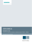
SINAMICS G150
75 kW to 1500 kW
SINAMICS G150
Version A and C
Operating Instructions
User Documentation
Safety Information
1
Device Overview
2
Mechanical Installation
3
Electrical Installation
4
Commissioning
5
Operation
6
Setpoint Channel and
7
Closed-Loop Control
8
Functions, Monitoring,
and Protective
Functions
9
Diagnosis / Faults and
10
Alarms
Valid for
Converter type
SINAMICS G150
Output Terminals
Control version
V2.3
Maintenance and
Servicing
Technical Data
List of Abbreviations
Index
Parameter Macros
Edition 06/05
11
12
06/05
Contents
For further information please visit us at:
http://www.ad.siemens.de
The reproduction, transmission or use of this
document or its contents is not permitted without
express written permission. Offenders will be liable for
damages. All rights, including rights created by patent
grant or registration of a utility model or design, are
reserved.
We have checked the contents of this document for
agreement with the hardware and software described.
Nonetheless, differences might exist and therefore we
cannot guarantee that they are completely identical.
However, the data in this manual is reviewed regularly and
any necessary corrections included in subsequent editions.
We are thankful for any recommendations or suggestions.
© Siemens AG 2005. All rights reserved.
We reserve the right to make technical changes.
Siemens AG
ii
SINAMICS G150
Operating Instructions
06/05
Contents
Preface
User documentation
WARNING
Before installing and commissioning the converter, make sure that you read all the
safety notes and warnings carefully, including the warning labels on the equipment
itself. The warning labels must always be legible. Missing or damaged labels must
be replaced.
Further information is available from:
Technical support
Tel:
+49 (0) 180 50 50 222
Fax:
+49 (0) 180 50 50 223
Internet:
http://www.siemens.com/automation/support-request
Internet Address
Information about SINAMICS can be found on the Internet at the following address:
http://www.siemens.com/sinamics
SINAMICS G150
Operating Instructions
iii
Contents
06/05
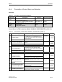
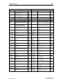
Contents
1 Safety Information
1.1
1.2
Definitions and Warning Information ................................................................... 1-1
Safety and Operating Instructions....................................................................... 1-3
2 Device Overview
2.1
2.2
2.2.1
2.2.2
2.3
2.3.1
2.3.2
2.4
2.5
3.3.1
3.3.2
3.3.3
3.3.4
3.3.5
3.3.6
Applications ......................................................................................................................2-2
Features ...........................................................................................................................2-2
Design ................................................................................................................. 2-3
Version A ..........................................................................................................................2-4
Version C..........................................................................................................................2-8
Wiring Principle ................................................................................................... 2-9
Type Plate ......................................................................................................... 2-13
4.6.1
4.6.2
4.6.3
4.6.4
4.7
4.7.1
4.7.2
4.7.3
4.7.4
4.7.5
4.7.6
4.8
4.8.1
4.8.2
iv
3-1
Chapter Content .................................................................................................. 3-1
Transportation and Storage ................................................................................ 3-2
Installation ........................................................................................................... 3-4
Mechanical Installation: Checklist .....................................................................................3-4
Preparatory Steps.............................................................................................................3-5
Installation ........................................................................................................................3-6
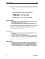
Mechanically connecting separately shipped transport units ............................................3-6
Fitting Additional Canopies (Option M21) or Hoods (Option M23 / M54) ..........................3-7
Cable Entry from Above (Option M13), Motor Connection from Above (Option M78) ....3-10
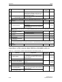
4 Electrical Installation
4.1
4.2
4.3
4.4
4.5
4.6
2-1
Chapter Content .................................................................................................. 2-1
Applications, Features, and Design .................................................................... 2-2
3 Mechanical Installation
3.1
3.2
3.3
1-1
4-1
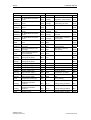
Chapter Content .................................................................................................. 4-1
Electrical Installation: Checklist........................................................................... 4-2
Important Safety Precautions.............................................................................. 4-6
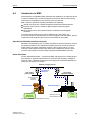
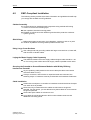
Introduction to EMC............................................................................................. 4-7
EMC-Compliant Installation................................................................................. 4-9
Electrically connecting separately shipped transport units ............................... 4-11
Connecting the PE buses ...............................................................................................4-11
Connecting the DC link connections ...............................................................................4-11
Connecting-up the power supply and the signal cables..................................................4-12
Connecting-up the DRIVE-CLiQ topology.......................................................................4-12
Power Connections ........................................................................................... 4-13
Connection Cross-Sections, Cable Lengths ...................................................................4-13
Opening and closing the disconnect switch ....................................................................4-14
Connecting the Motor and Power Cables .......................................................................4-15
Adjusting the Fan Voltage (-U1-T10) ..............................................................................4-17
Adjusting the Internal Power Supply (-A1 -T10, Version A Only)....................................4-19
Removing the Connection Bracket for the Interference-Suppression Capacitor with
Operation from an Ungrounded Supply ..........................................................................4-20
External Supply of the Auxiliary Supply from a Secure Line............................. 4-21
230 V AC Auxiliary Supply..............................................................................................4-22
24 V DC Auxiliary Supply................................................................................................4-22
SINAMICS G150
Operating Instructions
06/05
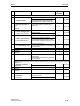
4.9
4.9.1
4.10
Contents
Signal Connections ........................................................................................... 4-23
Customer Terminal Block (-A60) ....................................................................................4-23
Other Connections ............................................................................................ 4-30
4.10.1
Main Contactor (Option L13) ..........................................................................................4-30
4.10.2
Sinusoidal Filter (Option L15) .........................................................................................4-31
4.10.3
Connection for External Auxiliary Equipment (Option L19).............................................4-33
4.10.4
Main Circuit-Breaker Incl. Fuses/Circuit-Breaker (Option L26) .......................................4-34
4.10.5
EMERGENCY OFF Button (Option L45) ........................................................................4-35
4.10.6
Cabinet Illumination with Service Socket (Option L50) ...................................................4-36
4.10.7
Cabinet Anti-Condensation Heating (Option L55)...........................................................4-36
4.10.8
EMERGENCY OFF Category 0; 230 V AC or 24 V DC (Option L57) .............................4-37
4.10.9
EMERGENCY OFF Category 1; 230 V AC (Option L59)................................................4-38
4.10.10 EMERGENCY OFF Category 1; 24 V DC (Option L60)..................................................4-39
4.10.11 25 kW Braking Unit (Option L61); 50 kW Braking Unit (Option L62)...............................4-40
4.10.12 Thermistor Motor Protection Unit (Option L83/L84) ........................................................4-45
4.10.13 PT100 Evaluation Unit (Option L86) ...............................................................................4-45
4.10.14 Insulation Monitor (Option L87) ......................................................................................4-47
4.10.15 Sensor Module SMC30 for Detecting the Actual Motor Speed (Option K50)..................4-48
4.10.15.1
Description..............................................................................................................4-48
4.10.15.2
Connection .............................................................................................................4-51
4.10.15.3
Connection Examples.............................................................................................4-53
4.10.16 Customer Terminal Block Extension (Option G61) .........................................................4-54
4.10.17 NAMUR Terminal Block (Option B00).............................................................................4-55
4.10.18 Separate 24 V DC Power Supply for NAMUR (Option B02) ...........................................4-57
4.10.19 Outgoing Section for External Auxiliary Equipment for NAMUR (Option B03)................4-57
4.10.20 PROFIdrive NAMUR (option B04) ..................................................................................4-58
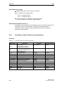
5 Commissioning
5.1
5.2
5.2.1
5.2.2
5.3
5.3.1
5.3.2
5.3.3
5.3.4
5.4
5.5
5.5.1
5.5.2
5.5.3
5.6
5.7
5.7.1
5.7.2
5.8
Chapter Content .................................................................................................. 5-1
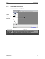
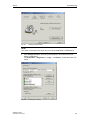
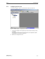
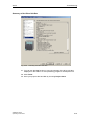
The STARTER Commissioning Tool................................................................... 5-2
Installing STARTER..........................................................................................................5-2
The STARTER User Interface ..........................................................................................5-3
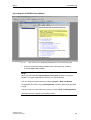
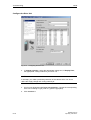
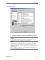
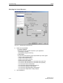
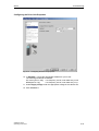
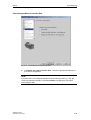
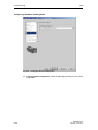
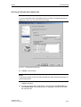
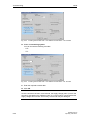
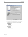
Commissioning Using STARTER........................................................................ 5-4
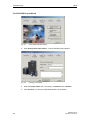
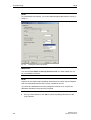
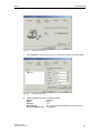
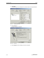
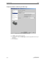
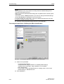
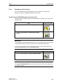
Creating Your Project .......................................................................................................5-4
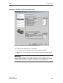
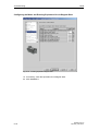
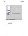
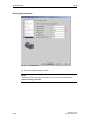
Configuring the Drive Unit...............................................................................................5-11
Additional and necessary settings for cabinet units with a high power rating .................5-28
Starting the Drive Project................................................................................................5-29
The Operator Panel (AOP30)............................................................................ 5-31
Initial Commissioning ........................................................................................ 5-32
Initial Ramp-Up...............................................................................................................5-32
Basic Commissioning .....................................................................................................5-33
Additional and necessary settings for cabinet units with a high power rating .................5-38
Status After Commissioning.............................................................................. 5-40
Data Backup...................................................................................................... 5-41
Saving the CompactFlash Card Parameter Settings ......................................................5-41
Restoring the Saved Configuration.................................................................................5-41
Resetting Parameters to the Factory Settings .................................................. 5-42
6 Operation
6.1
6.2
6.3
6.3.1
6.3.1.1
6.3.1.2
6.3.2
6.3.3
6.3.4
5-1
6-1
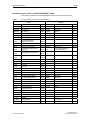
Chapter Content .................................................................................................. 6-1
General Information About Command and Setpoint Sources............................. 6-2
Basic Information About the Drive System.......................................................... 6-3
Parameters .......................................................................................................................6-3
Parameter Types ..............................................................................................................6-3
Parameter Categories.......................................................................................................6-4
Drive Objects ....................................................................................................................6-6
Data Sets..........................................................................................................................6-8
BICO Technology: Interconnection of Signals ................................................................6-14
SINAMICS G150
Operating Instructions
v
Contents
6.4
6.4.1
6.4.2
6.4.3
6.4.4
6.5
6.5.1
6.5.2
6.5.3
6.6
6.6.1
6.6.2
6.6.2.1
6.6.2.2
6.6.2.3
6.6.3
6.6.4
6.6.5
6.7
6.7.1
6.7.2
6.7.3
6.7.4
6.7.5
6.7.5.1
6.7.5.2
6.7.6
6.7.6.1
6.7.6.2
6.7.6.3
6.7.6.4
6.7.6.5
6.7.7
6.7.7.1
6.7.7.2
6.7.7.3
6.7.7.4
6.7.7.5
6.7.7.6
6.7.7.7
6.7.7.8
6.7.8
6.7.9
6.7.10
06/05
Command Sources............................................................................................ 6-19
PROFIBUS" Default Setting ...........................................................................................6-19
"TM31 Terminals" Default Setting...................................................................................6-21
"NAMUR" Default Setting ...............................................................................................6-23
"PROFIdrive NAMUR" Default Setting............................................................................6-25
Setpoint Sources ............................................................................................... 6-27
Analog Inputs..................................................................................................................6-27
Motorized Potentiometer.................................................................................................6-29
Fixed Speed Setpoints....................................................................................................6-30
PROFIBUS ........................................................................................................ 6-31
PROFIBUS Connection ..................................................................................................6-31
Control via PROFIBUS ...................................................................................................6-34
General information ........................................................................................................6-34
Setting the PROFIBUS Address .....................................................................................6-34
Setting the PROFIBUS Ident Number.............................................................................6-35
Telegrams and Process Data .........................................................................................6-35
Description of Control Words and Setpoints ...................................................................6-37
Description of Status Words and Actual Values .............................................................6-40
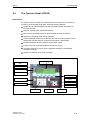
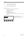
Control via the Operator Panel.......................................................................... 6-46
Operator Panel (AOP30) Overview ................................................................................6-46
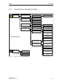
Menu Structure of the Operator Panel ............................................................................6-47
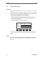
Operation Screen Menu..................................................................................................6-48
Parameterization Menu...................................................................................................6-49
Fault Memory / Alarm Memory .......................................................................................6-50
Faults..............................................................................................................................6-50
Alarms ............................................................................................................................6-50
Commissioning / Service Menu ......................................................................................6-51
Drive Commissioning......................................................................................................6-51
Device Commissioning ...................................................................................................6-51
AOP30 Settings ..............................................................................................................6-51
Lists of Signals for the Operation Screen .......................................................................6-52
AOP30 Diagnosis ...........................................................................................................6-55
Operation via the Operator Panel (LOCAL Mode) ..........................................................6-56
LOCAL/REMOTE Key ....................................................................................................6-56
ON / OFF Key.................................................................................................................6-57
Switching Between Clockwise and Counter-Clockwise Rotation ....................................6-57
Jog 6-58
Increase Setpoint / Decrease Setpoint ...........................................................................6-58
AOP Setpoint..................................................................................................................6-58
Timeout Monitoring .........................................................................................................6-59
Operator Input Inhibit / Parameterization Inhibit .............................................................6-59
Faults and Alarms...........................................................................................................6-61
Saving the Parameters Permanently ..............................................................................6-63
Parameterization Errors..................................................................................................6-63
7 Setpoint Channel and Closed-Loop Control
7.1
7.2
7.2.1
7.2.2
7.2.3
7.2.4
7.2.5
7.3
7.3.1
7.3.2
7.4
7.4.1
7.4.2
7.4.3
vi
7-1
Chapter Content .................................................................................................. 7-1
Setpoint Channel................................................................................................. 7-3
Setpoint Addition ..............................................................................................................7-3
Direction of Rotation Changeover.....................................................................................7-4
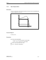
Suppression Speed and Minimum Speed.........................................................................7-5
Speed Limitation...............................................................................................................7-6
Ramp-Function Generator ................................................................................................7-7
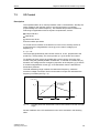
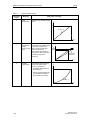
V/f Control ........................................................................................................... 7-9
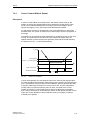
Voltage Boost .................................................................................................................7-12
Slip Compensation .........................................................................................................7-15
Vector Speed / Torque Control With / Without Encoder ................................... 7-16
Vector Control Without Sensor .......................................................................................7-17
Vector Control with Encoder ...........................................................................................7-19
Speed Controller.............................................................................................................7-20
SINAMICS G150
Operating Instructions
06/05
7.4.3.1
7.4.3.2
7.4.3.3
7.4.3.4
7.4.4
7.4.5
Contents
Speed controller pre-control (integrated pre-control with balancing) ..............................7-23
Reference model ............................................................................................................7-26
Speed controller adaptation............................................................................................7-27
Droop Function ...............................................................................................................7-29
Closed-loop torque control..............................................................................................7-31
Torque limiting ................................................................................................................7-33
8 Output Terminals
8.1
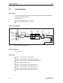
8.2
8.3
Chapter Content .................................................................................................. 8-1
Analog Outputs.................................................................................................... 8-2
Digital Outputs..................................................................................................... 8-5
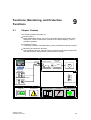
9 Functions, Monitoring, and Protective Functions
9.1
9.2
9.2.1
9.2.1.1
9.2.1.2
9.2.2
9.2.3
9.2.4
9.2.4.1
9.2.4.2
9.2.4.3
9.2.5
9.2.5.1
9.2.5.2
9.2.5.3
9.2.5.4
9.2.5.5
9.2.6
9.2.7
9.2.8
9.2.9
9.3
9.3.1
9.3.1.1
9.3.1.2
9.3.1.3
9.3.2
9.3.2.1
9.3.2.2
9.3.2.3
9.3.3
9.3.3.1
9.3.3.2
9.4
9.4.1
9.4.2
9.4.3
9.4.4
9.4.5
10.2.1
10.2.2
10.2.3
9-1
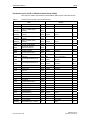
Chapter Content .................................................................................................. 9-1
Drive Functions ................................................................................................... 9-3
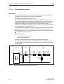
Motor Identification and Automatic Speed Controller Optimization...................................9-3
Standstill Measurement ....................................................................................................9-4
Rotating Measurement and Speed Controller Optimization..............................................9-5
Vdc Control.......................................................................................................................9-8
Automatic Restart ...........................................................................................................9-13
Flying Restart .................................................................................................................9-14
Flying Restart Without Encoder ......................................................................................9-15
Flying Restart with Encoder............................................................................................9-16
Parameters .....................................................................................................................9-16
Motor changeover...........................................................................................................9-17
Description......................................................................................................................9-17
Example of changing over between two motors .............................................................9-17
Example of a star / delta changeover .............................................................................9-19
Function diagram ............................................................................................................9-21
Parameters .....................................................................................................................9-21
Friction characteristic......................................................................................................9-22
Increasing the Output Frequency ...................................................................................9-24
Runtime (Operating Hours Counter) ...............................................................................9-25
Simulation operation .......................................................................................................9-26
Extended Functions........................................................................................... 9-27
Technology Controller.....................................................................................................9-27
Description......................................................................................................................9-27
Commissioning ...............................................................................................................9-28
Example: Liquid Level Control ........................................................................................9-29
Extended Braking Control...............................................................................................9-30
Description......................................................................................................................9-30
Commissioning ...............................................................................................................9-30
Examples........................................................................................................................9-30
Extended Monitoring Functions ......................................................................................9-32
Description......................................................................................................................9-32
Commissioning ...............................................................................................................9-33
Monitoring and Protection Functions................................................................. 9-34
Protecting Power Components: General ........................................................................9-34
Thermal Monitoring and Overload Responses ...............................................................9-35
Block Protection..............................................................................................................9-37
Stall Protection (Vector Control Only) .............................................................................9-38
Thermal Motor Protection ...............................................................................................9-39
10 Diagnosis / Faults and Alarms
10.1
10.2
8-1
10-1
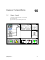
Chapter Content ................................................................................................ 10-1
Diagnosis........................................................................................................... 10-2
Diagnosis Using LEDs ....................................................................................................10-2
Diagnosis via Parameters...............................................................................................10-6
Indicating and Rectifying Faults......................................................................................10-9
SINAMICS G150
Operating Instructions
vii
Contents
10.3
10.3.1
10.3.2
10.3.3
10.4
06/05
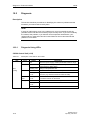
Overview of Faults and Alarms ....................................................................... 10-10
"External Warning 1".....................................................................................................10-10
"External Fault 1" ..........................................................................................................10-11
"External Fault 3" ..........................................................................................................10-11
Service and Support........................................................................................ 10-12
11 Maintenance and Servicing
11.1
11.2
11.2.1
11.3
11.3.1
11.4
11.4.1
11.4.2
11.4.3
11.4.4
11.4.5
11.4.6
11.4.7
11.4.8
11.4.9
11.4.10
11.4.11
11.4.12
11.4.13
11.4.14
11.4.15
11.4.16
11.4.17
11.4.18
11.5
11.6
11.7
11.8
Chapter Content ................................................................................................ 11-1
Maintenance...................................................................................................... 11-2
Cleaning .........................................................................................................................11-2
Servicing............................................................................................................ 11-3
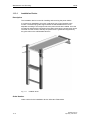
Installation Device ..........................................................................................................11-4
Replacing Components ..................................................................................... 11-5
Replacing the Filter Mats (Options M23 and M54) .........................................................11-5
Replacing the Power Block (Type FX) ............................................................................11-6
Replacing the Power Block (Type GX) ...........................................................................11-8
Replacing the Power Block (Type HX) .........................................................................11-10
Replacing the Power Block (Type JX) ..........................................................................11-14
Replacing the Control Interface Board (Type FX).........................................................11-18
Replacing the Control Interface Board (Type GX) ........................................................11-20
Replacing the Control Interface Board (Type HX) ........................................................11-22
Replacing the Control Interface Board (Type JX) .........................................................11-24
Replacing the Fan (Type FX)........................................................................................11-26
Replacing the Fan (Type GX) .......................................................................................11-28
Replacing the Fan (Type HX) .......................................................................................11-30
Replacing the Fan (Type JX) ........................................................................................11-34
Replacing the Fan Fuses (-U1-F10/-U1-F11) ...............................................................11-38
Replacing the Fuses for the Auxiliary Power Supply (-A1-F11/-A1-F12) ......................11-38
Replacing Fuse -A1-F21...............................................................................................11-38
Replacing the Cabinet Operator Panel .........................................................................11-39
Replacing the Backup Battery of the Cabinet Operator Panel ......................................11-39
Reforming the DC Link Capacitors.................................................................. 11-41
Messages after replacing DRIVE-CLiQ components...................................... 11-42
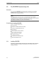
Upgrading the Cabinet Unit Firmware............................................................. 11-42
Loading the new operator panel firmware and database from the PC ........... 11-44
12 Technical Data
12.1
12.2
12.2.1
12.2.2
12.3
12.3.1
12.3.2
12.3.3
12.3.4
12.3.5
12.3.6
11-1
12-1
Chapter Content ................................................................................................ 12-1
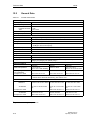
General Data ..................................................................................................... 12-2
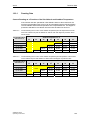
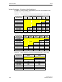
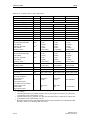
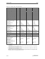
Derating Data .................................................................................................................12-3
Overload Capability ........................................................................................................12-7
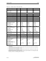
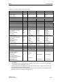
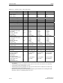
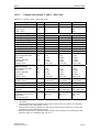
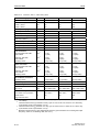
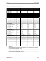
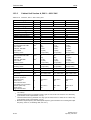
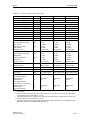
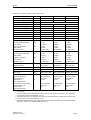
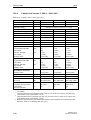
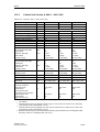
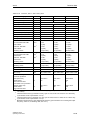
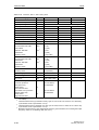
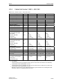
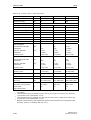
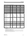
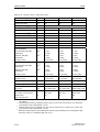
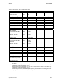
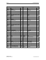
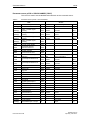
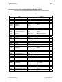
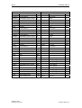
Technical Data .................................................................................................. 12-8
Cabinet Unit Version A, 380 V – 480 V 3AC...................................................................12-9
Cabinet Unit Version C, 380 V – 480 V 3AC.................................................................12-13
Cabinet Unit Version A, 500 V – 600 V 3AC.................................................................12-16
Cabinet Unit Version C, 500 V – 600 V 3AC.................................................................12-20
Cabinet Unit Version A, 660 V – 690 V 3AC.................................................................12-23
Cabinet Unit Version C, 660 V – 690 V 3AC.................................................................12-29
viii
SINAMICS G150
Operating Instructions
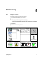
Safety Information
1
1.1
1
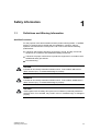
Definitions and Warning Information
Qualified Personnel
For the purpose of this documentation and the product warning labels, a “qualified
person” is someone who is familiar with the installation, mounting, start-up,
operation and maintenance of the product. He or she must have the following
qualifications:
• Trained or authorized to energize, de-energize, ground, and tag circuits and
equipment in accordance with established safety procedures.
• Trained in the proper care and use of protective equipment in accordance with
established safety procedures.
• First aid training.
DANGER
Indicates an imminently hazardous situation which, if not avoided, will result in
death, serious injury, or substantial damage to property.
WARNING
Indicates an imminently hazardous situation which, if not avoided, could result in
death, serious injury, or substantial damage to property.
CAUTION
Used together with the safety alert symbol, this indicates a potentially hazardous
situation which, if not avoided, may result in minor or moderate injury or damage to
property.
SINAMICS G150
Operating Instructions
1-1
Safety Information
06/05
CAUTION
Used without the safety alert symbol, this indicates a potentially hazardous
situation which, if not avoided, may result in damage to property.
IMPORTANT
Used without the safety alert symbol, this indicates a potential situation which, if
not avoided, may lead to an undesirable result or state.
NOTE
This symbol always appears in this documentation where further, explanatory
information is provided.
WARNING
Hazardous voltages are present in this electrical equipment during operation.
Non-observance of the warnings can result in severe personal injury or property
damage.
Only qualified personnel should work on or around the equipment.
This personnel must be thoroughly familiar with all warning and maintenance
procedures described in this documentation.
The successful and safe operation of this device is dependent on correct transport,
proper storage and installation, as well as careful operation and maintenance.
National safety guidelines must be observed.
Certification
The following certificates can be found under “Safety and Operating Instructions” in
the documentation folder:
• EU declaration of conformity
• Certificate of compliance with order
• EU manufacturer’s declaration
1-2
SINAMICS G150
Operating Instructions
06/05
1.2
Safety Information
Safety and Operating Instructions
DANGER
This equipment is used in industrial high-voltage installations. During operation,
this equipment contains rotating and live, bare parts. For this reason, they could
cause severe injury or significant material damage if the required covers are
removed, if they are used or operated incorrectly, or have not been properly
maintained.
When the machines are used in non-industrial areas, the installation location must
be protected against unauthorized access (protective fencing, appropriate signs).
Requirements
Those responsible for protecting the plant must ensure the following:
• The basic planning work for the plant and the transport, assembly, installation,
commissioning, maintenance, and repair work is carried out by qualified
personnel and/or checked by experts responsible.
• The operating manual and machine documentation are always available.
• The technical data and specifications regarding the applicable installation,
connection, environmental, and operating conditions are always observed.
• The plant-specific assembly and safety guidelines are observed and personal
protection equipment is used.
• Unqualified personnel are forbidden from using these machines and working
near them.
This operating manual is intended for qualified personnel and only contain
information and notes relating to the intended purpose of the machines.
The operating manual and machine documentation are written in different
languages as specified in the delivery contracts.
NOTE
The services and support provided by the SIEMENS service centers are
recommended for planning, installation, commissioning, and servicing work.
SINAMICS G150
Operating Instructions
1-3
Safety Information
06/05
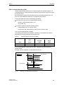
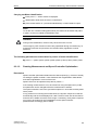
Components that can be Destroyed by Electrostatic Discharge (ESD)
CAUTION
The board contains components that can be destroyed by electrostatic discharge.
These components can be easily destroyed if not handled properly. If you do have
to use electronic boards, however, please observe the following:
• You should only touch electronic boards if absolutely necessary.
• When you touch boards, however, your body must be electrically discharged
beforehand.
• Boards must not come into contact with highly insulating materials (such as
plastic parts, insulated desktops, articles of clothing manufactured from manmade fibers).
• Boards must only be placed on conductive surfaces.
• Boards and components should only be stored and transported in conductive
packaging (such as metalized plastic boxes or metal containers).
• If the packaging material is not conductive, the boards must be wrapped with a
conductive packaging material (such as conductive foam rubber or household
aluminum foil).
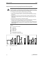
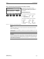
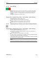
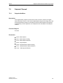
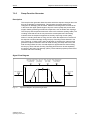
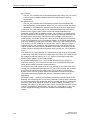
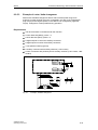
The necessary ESD protective measures are clearly illustrated in the following
diagram:
• a = conductive floor surface
• b = ESD table
• c = ESD shoes
• d = ESD overall
• e = ESD chain
• f = cabinet ground connection
• g = contact with conductive flooring
d
d
b
b
e
e
f
g
a
c
f
f
c
Sitting
Fig. 1-1
d
Standing
a
f
f
g c
a
Standing/sitting
ESD protective measures
1-4
SINAMICS G150
Operating Instructions
Device Overview
2
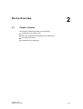
2.1
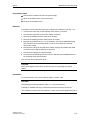
2
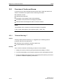
Chapter Content
This chapter provides information on the following:
• Introduction to the cabinet units
• The main components and features of the cabinet unit
• The cabinet unit wiring
• Explanation of the type plate
SINAMICS G150
Operating Instructions
2-1
Device Overview
2.2
Applications, Features, and Design
2.2.1
Applications
06/05
SINAMICS G150 drive converter cabinet units are specially designed to meet the
requirements of drives with a quadratic and constant load characteristic, medium
performance requirements, and no regenerative feedback. Applications include:
• Pumps and fans
• Compressors
• Extruders and mixers
• Mills
2.2.2
Features
The accuracy of sensorless vector control ensures that the system can be used for
a wide variety of applications and, as a result, an additional speed sensor is not
required.
SINAMICS G150 takes this into account and, as a result, offers a low-cost drive
solution tailored to actual requirements.
In addition, factors have been considered to ensure easy handling of the drive from
the planning and design phase through to operation. These factors include:
• Compact, modular, service-friendly design
• Straightforward planning and design
• Ready to connect to facilitate the installation process
• Quick, menu-driven commissioning with no complex parameterization
• Clear and convenient operation via a user-friendly graphical operator panel with
measured values displayed in plain text or in a quasi-analog bar display.
• SINAMICS is an integral part of Totally Integrated Automation (TIA). The TIA
concept offers an optimized range of products for automation and drive
technology. This concept is characterized by planning / design, communication,
and data management procedures that are consistent throughout the product
range. SINAMICS is totally integrated in the TIA concept.
Separate S7/PCS7 blocks and faceplates for WinCC are available.
2-2
SINAMICS G150
Operating Instructions
06/05
Device Overview
Quality
The SINAMICS G150 drive converter cabinet units are manufactured to meet high
standards of quality and exacting demands.
This results in a high level of reliability, availability, and functionality for our
products.
The development, design, and manufacturing processes, as well as order
processing and the logistics supply center have been independently certified to
DIN ISO 9001.
Service
Our worldwide sales and service network offers our customers individual
consultations, provides support with planning and design, and offers a range of
training courses.
For detailed contact information and the current link to our Internet pages, see
10.3.
2.3
Design
The SINAMICS G150 cabinet units are characterized by their compact, modular,
and service-friendly design.
A wide range of electrical and mechanical components enable the drive system to
be optimized for the appropriate requirements.
Two cabinet unit versions are available depending on the options that are chosen.
SINAMICS G150
Operating Instructions
2-3
Device Overview
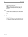
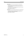
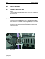
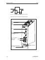
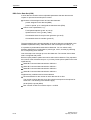
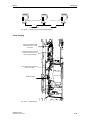
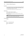
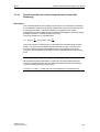
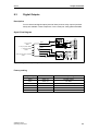
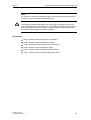
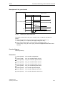
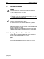
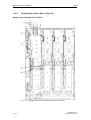
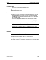
2.3.1
06/05
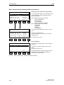
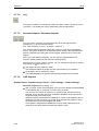
Version A
All the required power supply connection components, such as the main circuitbreaker, circuit-breakers, main contactor, line fuses, radio interference suppression
filter, motor components, and additional protection and monitoring devices, can be
installed as required.
The cabinet unit comprises up to four cabinet panels with a total width of between
800 and 3200 mm, depending on the output.
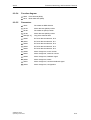
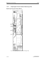
Line reactor (-L1)
Operator panel
Power Module (-U1)
Emergency off
Control Unit CU320
(-A10)
Main circuit-breaker
(-Q1)
Door interlock
Customer terminal
block (-A60)
Ventilation grilles
(depending on degree
of protection)
Line connection (-X1)
Motor connection
(-X2)
Fig. 2-1
2-4
Example of a cabinet unit, version A (e.g. 132 kW, 400 V 3AC)
(some components are optional)
SINAMICS G150
Operating Instructions
06/05
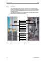
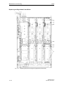
Device Overview
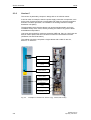
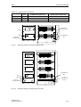
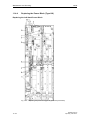
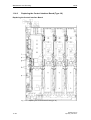
Version A, high power rating using a parallel circuit
For very high power ratings, the cabinet drive comprises two cabinet units that
together drive a motor in a parallel circuit configuration:
• for 3-ph. 380 V – 480 V AC:
6SL3710-2GE41-1AA0, 6SL3710-2GE41-4AA0, 6SL3710-2GE41-6AA0
• for 3-ph. 500 V – 600 V AC:
6SL3710-2GF38-6AA0, 6SL3710-2GF41-1AA0, 6SL3710-2GF41-4AA0
• for 3-ph. 660 V – 690 V AC:
6SL3710-2GH41-1AA0, 6SL3710-2GH41-4AA0, 6SL3710-2GH41-5AA0
Customer terminal strip
(-A60)
Line connection
(-X1)
Motor
connection (-X2)
Main switch (-Q1)
Location code:
+H.A24
Power Module (-U1)
Location code:
+H.A49
Lefthand cabinet section
Fig.2-2
Control Unit CU320
(-A10)
Line connection
(-X1)
Motor
connection (-X2)
Main switch (-Q1)
Location code:
+H.A25
Operator panel
Power Module (-U1)
Location code:
+H.A50
Righthand cabinet section
Example of the cabinet drive, version A (e.g. 1500 kW, 3-ph. 690 V AC),
(components in some cases optional)
SINAMICS G150
Operating Instructions
2-5
Device Overview
06/05
Special features when connecting-up and operating cabinet drive units in a
parallel circuit configuration
The cabinet drive units can be connected to the line supply in either a 6-pulse or
12-pulse connection.
For a 6-pulse connection, the following special issues apply:
• The DC links may not be connected with one another, the disconnect switch (Q98, -Q99) must be open.
• Only motors with separate winding systems may be used; every motor
connection of a sub-cabinet must be connected to its own winding system.
Parameter p7003 (winding system) must be set to "1" (several separate winding
systems or motors).
• Edge modulation is not possible.
For a 12-pulse connection, the following special issues apply:
• The 12-pulse connection to the line supply is only possible using a double-tier
transformer with three winding systems or two single transformers with two
electrical winding systems on the transformer secondary offset through 30° with
respect to one another.
Transformer vector groups Dy5Dd0 or Dy11Dd0 should be preferably used.
When using sub-windings that are electrically offset with respect to one another,
the line harmonics are reduced with respect to the 6-pulse infeed.
The following requirements apply for the transformer:
–
The open-circuit voltages of the two secondary windings must not differ
more than a maximum of 0.5% (referred to rated voltage).
–
The deviations of the short-circuit impedances of the two secondary
windings must be less than 5 % of the rated value.
–
The minimum short-circuit impedance of the transformer should be 4 %.
• The DC links must be connected with one another, the disconnect switch
(-Q98, -Q99) must be closed.
• The feedback signal contacts of the main contactors and the circuit-breakers
are connected in series in the factory and are connected to digital input 7 of the
Control Unit.
When commissioning the drive, the monitoring function of the feedback signals
must be activated.
This is realized using parameter p0860{Vector} = 722.7{Control Unit}.
• Motors with two electrically isolated winding systems and also motors with one
winding system can be used.
2-6
SINAMICS G150
Operating Instructions
06/05
Device Overview
When connecting a motor with one winding system, the following special
features apply.
–
The motor connections of the Power Modules can be connected to one
another per phase. Parameter p7003 (winding system) must be set to "0"
(one winding systems).
–
If a motor reactor is not being used (option L08), the minimum motor cable
lengths must be used – refer to Chapter 4.
–
Edge modulation is not possible.
When connecting a motor with separate winding systems, the following special
points apply.
–
Every motor connection of a Power Module must be connected to its own
winding system. Parameter p7003 (winding system) must be set to "1"
(several separate winding systems or motors).
–
Edge modulation is not possible.
SINAMICS G150
Operating Instructions
2-7
Device Overview
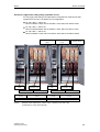
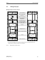
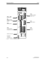
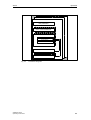
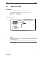
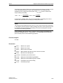
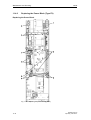
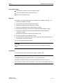
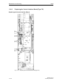
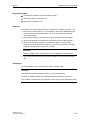
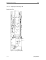
2.3.2
06/05
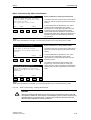
Version C
This version is particularly compact in design with an in-built line reactor.
It can be used, for example, when the power supply connection components, such
as the main contactor and main circuit-breaker with fuses for conductor protection
and semi-conductor protection, are installed in an existing central low-voltage
distribution unit (MCC).
The advantage here is that the cabinet unit can be sited decentrally and in the
immediate vicinity of the motor, thereby avoiding the need for long motor cables
and additional output filters.
Line fuses are required for conductor protection (VDE 636, Part 10). Line fuses can
also be used to protect the semi-conductors of the line-commutated converter
(VDE 636, Part 40/ EN 60 269-4).
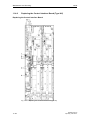
The cabinet unit simply comprises a single cabinet with a width of 400 mm,
600 mm, or 1000 mm.
Operator panel
Power Module (-U1)
Control Unit CU320
(-A10)
Door interlock
Customer terminal
block (-A60)
Ventilation grilles
(depending on degree
of protection)
Motor connection
(-X2)
Line connection (-X1)
Line reactor (-L1)
Fig. 2-3
2-8
Example of a cabinet unit, version C (e.g. 315 kW, 690 V 3AC)
SINAMICS G150
Operating Instructions
06/05
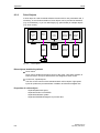
2.4
Device Overview
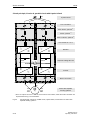
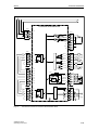
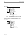
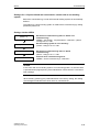
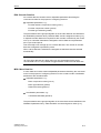
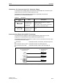
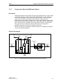
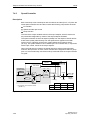
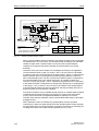
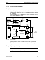
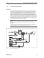
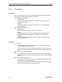
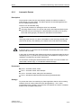
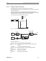
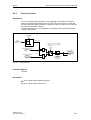
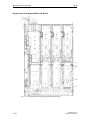
Wiring Principle
Wiring principle: versions A and C
PE
Line connection
PE
Main circuit-breaker
(optional) 1)
Main fuses (optional)
1)
Main contactor
(optional) 1)
~
~
Line reactor Uk = 2%
< 500 kW standard
> 500 kW only available as
option (L23)
Rectifier
=
~
~
=
Voltage DC link
R2
R1
=
Braking chopper (optional)
~
~
Inverter
PE
~
~
Motor connection
Version A
1)
=
PE
Version C
The main-circuit breaker, fuse, and main contactor functions are implemented as of an
output current of > 800 A by means of circuit-breakers.
Fig. 2-4
Wiring principle: versions A and C
SINAMICS G150
Operating Instructions
2-9
Device Overview
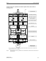
06/05
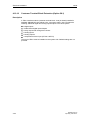
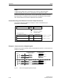
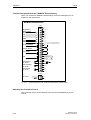
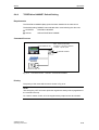
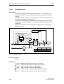
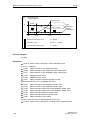
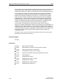
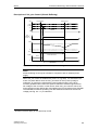
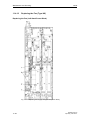
Circuit principle, Version A, parallel circuit with 6-pulse infeed
PE
6-pulse infeed
PE
PE
Line connection
Main switch, optional
Fuses, optional
1)
1)
Main contactor, optional
1)
Line reactor Uk = 2 %
~
~
~
~
=
-Q98
DCPS
DCNS
=
=
Separate voltage DC link
DCPS
DCNS
-Q99
=
~
~
Rectifier
PE
~
~
Inverter
PE
Motor connection
PE
1U2
1V2
1W2
1)
2U2
2V2
2W2
Motor with separate
winding systems
From an output current of > 800 A, the functions main switch, fuses and main contactor are
implemented using a circuit-breaker
Fig.2-5
2-10
M
~
Circuit principle, Version A, parallel circuit, 6-pulse infeed, connected to one motor with
separate winding systems.
SINAMICS G150
Operating Instructions
06/05
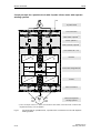
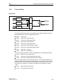
Device Overview
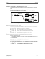
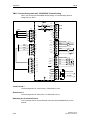
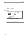
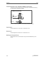
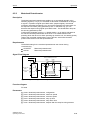
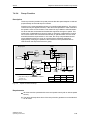
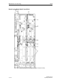
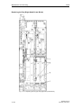
Circuit principle for a parallel circuit with 12-pulse infeed, motor with one
winding system
PE
12-pulse infeed
PE
PE
Line supply connection
Main switch, optional
Fuses, optional
1)
1)
Main contactor, optional
1)
Line reactor Uk = 2 %
~
~
~
~
=
-Q98
DCPS
DCNS
=
=
~
~
Inverter
PE
M
~
Fig.2-6
Connected voltage DC link
DCNS
PE
1)
=
DCPS
-Q99
~
~
Rectifier
PE
Motor connection
Motor with one
winding system
From an output current of > 800 A, the functions main switch, fuses and main contactor are
implemented using a circuit-breaker
Circuit principle, Version A, parallel circuit, 12-pulse infeed, connected to one motor with one
winding system.
SINAMICS G150
Operating Instructions
2-11
Device Overview
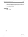
06/05
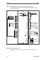
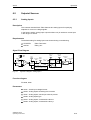
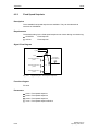
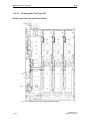
Circuit principle for a parallel circuit with 12-pulse infeed, motor with separate
winding systems
PE
12-pulse infeed
PE
PE
Line connection
Main switch, optional
Fuses, optional
1)
1)
Main contactor, optional
1)
Line reactor Uk = 2 %
~
~
~
~
=
-Q98
DCPS
DCNS
=
=
Connected voltage DC link
DCPS
DCNS
-Q99
=
~
~
Rectifier
PE
~
~
Inverter
PE
Motor connection
PE
1U2
1V2
1W2
1)
Fig.2-7
2-12
M
~
2U2
2V2
2W2
Motor with separate
winding systems
From an output current of > 800 A, the functions main switch, fuses and main contactor are
implemented using a circuit-breaker
Circuit principle for a parallel circuit, 12-pulse infeed, connected to a motor with separate
winding systems.
SINAMICS G150
Operating Instructions
06/05
Device Overview
IMPORTANT
The motor earth must be fed back directly to the cabinet unit.
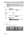
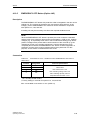
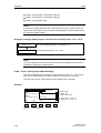
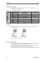
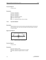
2.5
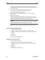
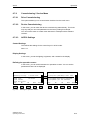
Type Plate
Device designation
List of device options
Month of manufacture
Year of manufacture
Fig. 2-8
Type plate for the cabinet unit
Date of Manufacture
The date of manufacture can be ascertained as follows:
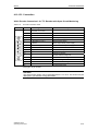
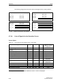
Table 2-1
Year and month of manufacture
Letter /
number
Year of manufacture
Letter /
number
Month of manufacture
S
2004
1 to 9
January to September
T
2005
O
October
V
2006
N
November
Y
2007
D
December
SINAMICS G150
Operating Instructions
2-13
Device Overview
06/05
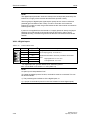
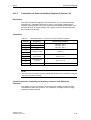
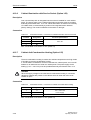
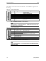
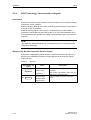
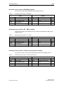
Type Plate Data (from Type Plate on Previous Page)
Table 2-2
Type plate data
Specification
Value
Input
3AC
380 – 480 V
239 A
Three-phase connection
Rated input voltage
Rated input current
Output
3AC
0 – 480 V
210 A
Three-phase connection
Rated output voltage
Rated output current
Temperature range
0 – 40°C
Ambient temperature range within which the cabinet unit can
operate under 100 % load
Degree of protection
IP20
Duty class
I
Cooling method
AF
Weight
Explanation
Degree of protection
I: Duty class I to EN 60146-1-1 = 100 % (continuously)
(with the specified current values, the cabinet unit can operate
continuously under 100 % load)
A: coolant: air
F: circulation method: forced cooling, drive unit (fan) in the
device
Weight of the cabinet unit
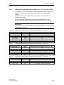
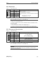
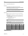
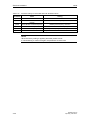
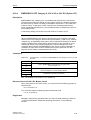
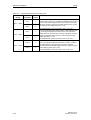
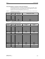
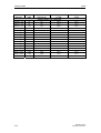
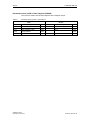
Explanation of the Option Short Codes
Table 2-3
Explanation of the option codes
Version
Input options
L00
Line filter for use in environment 1 to EN 61800-3, category C2
(TN/TT networks)
L13
Main contactor (for currents < 800 A)
L22
Without line reactor in power range P < 500 kW (available soon)
L23
Line reactor uk = 2 %, may be required for P > 500 kW
L26
Main circuit-breaker (incl. fuses/circuit-breakers)
Output options
L08
Motor reactor
L15
Sinusoidal filter (only for the voltage range 380 – 480 V, max. 200
kW)
Input and output options
M70
EMC shield bar (cable connection from below)
M75
PE busbar (cable connection from below)
2-14
A
C
•
−
•
•
•
•
−
•
•
−
•
•
−
−
•
•
•
•
SINAMICS G150
Operating Instructions
06/05
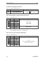
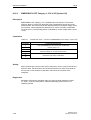
Device Overview
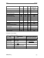
Version
A
C
•
•
−
−
•
•
•
•
•
•
•
−
−
−
−
−
−
•
Increase in degree of protection
M21
IP21 degree of protection
M23
IP23 degree of protection
M54
IP54 degree of protection
•
•
•
•
•
•
Mechanical options
M06
Plinth, 100 mm high, RAL 7022
M07
Cable wiring compartment, 200 mm high, RAL 7035
M13
Line connection from above
M78
Motor connection from above
M90
Top-mounted crane transport assembly for cabinets
•
•
•
•
•
•
•
−
−
•
Miscellaneous options
G61
Customer terminal block extension TM31
K50
Sensor Module (SMC30) for detecting the actual motor speed
L19
Connection for external auxiliary equipment (controlled max. 10 A)
L50
Cabinet illumination with service socket
L55
Cabinet standstill heating
L61
25 kW braking unit
L62
50 kW braking unit
Y09
Special paint finish for cabinet
•
•
•
•
•
•
•
•
−
−
−
−
−
−
−
•
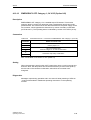
Languages
D58
Documentation in English / French
D60
Documentation in English / Spanish
D80
Documentation in English / Italian
T58
Type plate and operator panel in English / French
T60
Type plate and operator panel in English / Spanish
T80
Type plate and operator panel in English / Italian
•
•
•
•
•
•
•
•
•
•
•
•
Industry-specific options (chemicals)
B00
NAMUR terminal block
B02
Separate 24 V power supply (PELV)
B03
Outgoing section for external auxiliary equipment (uncontrolled)
B04
PROFIdrive NAMUR
•
•
•
•
−
−
−
−
Motor protection and safety functions
L45
EMERGENCY OFF button in the cabinet unit door
L57
EMERGENCY OFF category 0 (230 V AC or 24 V DC, uncontrolled
stop)
L59
EMERGENCY STOP category 1, 230 V AC, controlled stop
L60
EMERGENCY OFF category 1 (24 V AC, controlled stop)
L83
Thermistor motor protection unit with PTB approval (warning)
L84
Thermistor motor protection unit with PTB approval (shutdown)
L86
PT100 evaluation unit (for 6 PT100 sensors)
L87
Insulation monitoring
M60
Additional shock-hazard protection
•
−
indicates that this option is available for that version.
indicates that this option is not available for that version.
SINAMICS G150
Operating Instructions
2-15
Device Overview
06/05
2-16
SINAMICS G150
Operating Instructions
Mechanical Installation
3
3.1
3
Chapter Content
This chapter provides information on the following:
• The conditions for transporting, storing, and installing the cabinet unit
• Preparing and installing the cabinet unit
SINAMICS G150
Operating Instructions
3-1
Mechanical Installation
3.2
06/05
Transportation and Storage
Transportation
WARNING
The following must be taken into account when the devices are transported:
• The devices are heavy. Their center of gravity is displaced, and they can be top
heavy.
• Suitable hoisting gear operated by trained personnel is essential due to the
weight of the devices.
• The devices must only be transported in the upright position indicated. The
devices must not be transported upside down or horizontally.
• Serious injury or even death and substantial material damage can occur if the
devices are not lifted or transported properly.
NOTES regarding transportation
• The devices are packaged by the manufacturers in accordance with the climatic
conditions and stress encountered during transit and in the recipient country.
• The notes on the packaging for transportation, storage, and proper handling
must be observed.
• The devices must be carried on a wooden palette when transported with fork-lift
trucks.
• When the devices are unpacked, they can be transported using the optional
transport eyebolts (option M90) or rails on the cabinet unit. The load must be
distributed evenly. Heavy blows or impacts must be avoided during transit and
when the devices are being set down, for example.
• Permissible ambient temperatures:
Ventilation: -25°C to +70°C, class 2K3 to IEC 60 721-3-2
Up to -40°C for max. 24 hours
NOTES regarding built-in system-side components
If built-in system-side components are to be installed on doors or side panels, you
must take into account the following points:
• The degree of protection (IP20, IP21, IP23, IP54) must not be reduced as a
result.
• The electromagnetic compatibility of the cabinet unit must not be adversely
affected.
• When control elements are installed on side or rear panels, the panels must be
grounded separately.
3-2
SINAMICS G150
Operating Instructions
06/05
Mechanical Installation
NOTES regarding damage in transit
• Carry out a thorough visual inspection of the device before accepting the
delivery from the transportation company.
• Ensure that you have received all the items specified on the delivery note.
• Notify the transportation company immediately of any missing components or
damage.
• If you identify any hidden deficiencies or damage, contact the transportation
company immediately and ask them to examine the device.
• If you fail to contact them immediately, you may lose your right to claim
compensation for the deficiencies and damage.
• If necessary, you can request the support of your local Siemens branch.
WARNING
Damage in transit indicates that the device was subject to unreasonable stress.
The electrical safety of the device can no longer be ensured. It must not be
connected until a thorough high-voltage test has been carried out.
Death, serious injury, or substantial material damage can result if these factors are
not taken into account.
Storage
The devices must be stored in clean, dry rooms. Permissible temperatures:
between –25°C and +70°C. Temperature variations greater than 20 K per hour are
not permitted.
If the device is stored for a prolonged period once it has been unpacked, cover it or
take other appropriate measures to ensure that it does not become dirty and that it
is protected against environmental influences. If such measures are not taken, the
guarantee becomes invalid in the event of a claim for damages.
WARNING
The storage period should not exceed two years. If the device is stored for more
than two years, the DC link capacitors of the devices must be reformed during
commissioning.
The reforming procedure is described in "Maintenance and Servicing”.
SINAMICS G150
Operating Instructions
3-3
Mechanical Installation
3.3
06/05
Installation
WARNING
To ensure that the devices operate safely and reliably, they must be properly
installed and put into operation by qualified personnel, taking into account the
warning messages provided in this operating manual.
In particular, both the general and national installation and safety guidelines for
high-voltage installations (e.g. VDE – the Union of German Technical Engineers)
and the guidelines relating to the professional use of tools and the use of personal
protective equipment must be observed.
Death, serious injury, or substantial material damage can result if these factors are
not taken into account.
3.3.1
Mechanical Installation: Checklist
Use the following checklist to guide you through the mechanical installation
procedure for the cabinet unit. Read the safety notes at the start of this operating
manual before you start working on the device.
NOTE
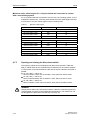
Check the boxes accordingly in the right-hand column if the activity applies to the
cabinet unit in your scope of supply. In the same way, check the boxes once you
have finished the installation procedure to confirm that the activities are complete.
Item
1
Activity
Fulfilled/Complete
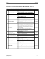
The ambient conditions must be permissible. See "Technical Data,
General Technical Data".
The cabinet unit must be firmly attached to the fixing points provided. With
version C with a width of 400 mm, the cabinet unit can, if required, be
secured to a non-flammable vertical surface by means of the wall support
supplied (see 3.3.2).
The cooling air can flow unobstructed.
2
The minimum ceiling height (for unhindered air outlet) specified in the
operating manual must be observed. The cooling air supply must be not
be obstructed (see 3.3.2).
3
Transport units separately shipped must be connected to one another
(refer to Chapter 3.3.4).
4
Components that are supplied separately for transport reasons (canopy or
hood) must be fitted (see 3.3.5).
5
The clearance around an open door (escape route) specified in the
applicable accident prevention guidelines must be observed.
6
For option M13/M78:
Choose the required metric screw connections or conduit thread
connections on the basis of the cable cross-section and drill the required
holes in the blanking plates. When the cable is fed in from above, ensure
that enough room is available if the cable has to be bent because of the
cable feeder and cross-sections. The cable entries should be fed in
vertically to minimize transverse forces on the entries (see 3.3.6).
3-4
SINAMICS G150
Operating Instructions
06/05
3.3.2
Mechanical Installation
Preparatory Steps
On-Site Requirements
The cabinet units are suitable for installation in general operating areas (DlN VDE
0558 / Edition 7.87, Part 1 / Section 5.4.3.2.4).
The standard specifies the following:
When power conversion units are installed in general operating areas, live parts
must be protected in such a way that they cannot be touched either directly or
indirectly.
The operating areas must be dry and free of dust. The air supplied must not
contain any electrically conductive gas, vapors, or dust, which could impair the
function of the devices. It may be necessary to filter the air supplied to the
installation room. If the air contains dust, filter mats (option M54) can be installed in
front of the hoods (IP54) and the ventilation grilles on the cabinet doors.
The ambient conditions for the units in the operating rooms must not exceed the
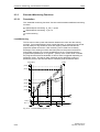
values of code F in accordance with EN 60146. At temperatures > 40°C (104°F)
and altitudes > 2000 m, the devices must be derated.
The basic version of the cabinet units complies with the IP20 degree of protection
in accordance with EN 60529.
The chassis units are installed in accordance with the dimension drawings
supplied. The clearance between the top of the cabinet unit and the ceiling is also
specified on the dimension drawings.
The cooling air for the power unit is drawn in from the front through the ventilation
grilles in the lower part of the cabinet doors. The warmed air is expelled through
the perforated top cover or the ventilation grilles in the top cover (with option
M13/M23/M54/M78). Cooling air can also be supplied from below through raised
floors or air ducts, for example. To allow this, you have to create openings in the 3section bottom plate.
According to EN 61800-3, the cabinet units are not suitable for use in low-voltage
public networks that supply residential buildings. High-frequency interference may
occur if they are used in this type of network.
Unpacking the Cabinets
Check the delivery against the delivery note to ensure that all the items have been
delivered. Check that the cabinet is intact.
The packaging material must be discarded in accordance with the applicable
country-specific guidelines and rules.
Required Tools
To install the cabinet, you will require:
• Spanner or socket spanner (w/f 10)
• Spanner or socket spanner (w/f 13)
• Spanner or socket spanner (w/f 16/17)
• Spanner or socket spanner (w/f 18/19)
• Hexagon-socket spanner (size 8)
• Torque spanner, max. 50 Nm
• Screwdriver, size 2
• Screwdriver Torx T20
• Screwdriver Torx T30
SINAMICS G150
Operating Instructions
3-5
Mechanical Installation
3.3.3
06/05
Installation
Lifting the Cabinet off the Transport Palette
The applicable local guidelines regarding the transportation of the cabinet from the
transport palette to the installation location must be observed.
A crane transport assembly (option M90) can also be fitted on the top of the
cabinet.
Installation
Four holes for M12 screws are provided on each cabinet panel to secure the
cabinet to the ground. The fixing dimensions are specified on the dimension
drawings enclosed.
Two wall supports for attaching the top of the cabinet to the wall are also supplied
for 400 mm-wide cabinets to provide extra security.
3.3.4
Mechanically connecting separately shipped transport units
The following cabinets are supplied in the form of two separate transport units:
• 3-ph. 500 V – 600 V AC:
6SL3710-2GF41-4AA0
• 3-ph. 660 V – 690 V AC:
6SL3710-2GH41-4AA0, 6SL3710-2GH41-5AA0
The lefthand sub-cabinet has the locator code "+H.A24" and "+H.A49", the
righthand sub-cabinet has the locator code "+H.A25" and "+H.A50" – the cabinet
operator panel is also mounted here.
A series of connectors is provided attached loose with the equipment to
mechanically connect the two sub-cabinets. These connectors should be attached
and as far as possible evenly distributed.
3-6
SINAMICS G150
Operating Instructions
06/05
Mechanical Installation
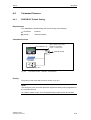
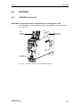
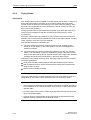
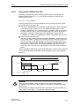
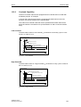
3.3.5
Fitting Additional Canopies (Option M21) or Hoods (Option M23 /
M54)
To increase the degree of protection of the cabinets from IP20 (standard) to IP21,
IP23, or IP54, additional canopies or hoods are supplied. These must be fitted
once the cabinets have been installed.
Description
The degree of protection can be increased to IP21 by fitting an additional canopy.
The canopy is flush-mounted with the cabinet unit and is fitted using spacers at a
distance of 250 mm above the top of the cabinet. As a result, cabinets with a
canopy are 250 mm higher.
Cabinet units with degree of protection IP23 are supplied with additional hoods, as
well as plastic ventilation grilles and braided plastic in the air inlet (doors) and outlet
(hoods). The hoods are flush with the cabinets at the side and front and have a
recess at the rear so that air can escape even if the cabinet is wall mounted. Air
escapes from the front and back. The hood is secured by means of the four holes
for the crane hook in the cabinet. Hoods increase the height of the cabinet by 400
mm.
Cabinet units with degree of protection IP54 are supplied with additional hoods,
plastic ventilation grilles, and a filter medium in the air inlet (doors) and outlet
(hoods). The filter mediums can be easily fitted and replaced from the outside. Air
escapes from the front and back. Compliance with degree of protection IP54
requires an intact filter medium, which must be replaced on a regular basis due to
the prevailing ambient conditions.
SINAMICS G150
Operating Instructions
3-7
Mechanical Installation
06/05
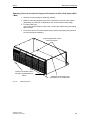
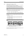
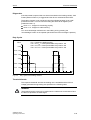
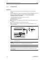
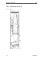
Attaching a Canopy to Increase the Degree of Protection to IP21 (Option M21)
1. Remove the crane transport assembly (if fitted).
2. Attach the spacers to the roof of the cabinet at the positions specified. You may
have to remove the protective grille.
3. Fit the canopy to the spacers.
Insert the enclosed screws from
above.
Insert the enclosed screws
from below.
Fig. 3-1
3-8
Cabinet with attached canopy
SINAMICS G150
Operating Instructions
06/05
Mechanical Installation
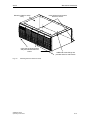
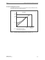
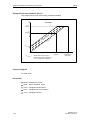
Attaching a Hood to Increase the Degree of Protection to IP23 / IP54 (Option M23
/ M54)
1. Remove the crane transport assembly (if fitted).
2. Make sure that the perforated top cover is not fitted on the top of the cabinet
(depending on production requirements, this can be fitted at a later stage).
3. For option M54 only:
Secure the contact surfaces of the hood on top of the cabinet using the sealing
tape provided.
4. Fit the hood to the roof of the cabinet at the positions specified (fixing points for
the crane transport assembly).
Insert original hood screws
M14 from above.
Insert the enclosed screws
and plain washers M8 from
below.
Fig. 3-2
Additional screw fittings are
provided here for wide hoods.
Attaching a hood
SINAMICS G150
Operating Instructions
3-9
Mechanical Installation
3.3.6
06/05
Cable Entry from Above (Option M13), Motor Connection from
Above (Option M78)
Cable Entry from Above
With options M13 and M78, the cabinet unit is equipped with an additional hood.
The connection straps for the power cables, the clamping bar for mechanically
securing the cables, an EMC shield bus, and a PE busbar are located within the
hood.
The hood adds an extra 405 mm to the cabinet height. The busbars for connection
from above are fully mounted when the system is delivered. For transport reasons,
the hoods are delivered separately and must be mounted on site. With options M23
and M54, plastic ventilation grilles and filter mats are also supplied.
A 5 mm aluminum mounting plate (with no holes) is fitted in the roof of the cover for
feeding in the cables. Depending on the number of cables and the cross-sections
used, holes for attaching cable glands for feeding in the cables must be drilled in
this mounting plate on site.
NOTE
The control cables and optional brake resistors are connected as before from
below.
Attaching the Hood
1. Remove the crane transport assembly (if fitted).
2. For option M54 only:
Secure the contact surfaces of the hood on top of the cabinet using the sealing
tape provided.
3. Fit the hood to the roof of the cabinet at the positions specified (fixing points for
the crane transport assembly).
4. To secure the power cables, remove the front panel of the hood.
3-10
SINAMICS G150
Operating Instructions
06/05
Mechanical Installation
Mounting plate for cable
entry
Insert the enclosed screws
and plain washers M8 from
below.
Fig. 3-3
Insert original hood screws
M14 from above.
Additional screw fittings are
provided here for wide hoods.
Attaching the hood with M13 / M78
SINAMICS G150
Operating Instructions
3-11
Mechanical Installation
06/05
3-12
SINAMICS G150
Operating Instructions
Electrical Installation
4
4.1
4
Chapter Content
This chapter provides information on the following:
• Establishing the electrical connections for the cabinet unit
• Adjusting the fan voltage and the internal power supply to local conditions
(supply voltage).
• The customer terminal block and its interfaces
• The interfaces for additional options
SINAMICS G150
Operating Instructions
4-1
Electrical Installation
4.2
06/05
Electrical Installation: Checklist
Use the following checklist to guide you through the electrical installation procedure
for the cabinet unit. Read the safety notes at the start of this operating manual
before you start working on the device.
NOTE
Check the boxes accordingly in the right-hand column if the activity applies to the
cabinet unit in your scope of supply. In the same way, check the boxes once you
have finished the installation procedure to confirm that the activities are complete.
Item
Activity
Fulfilled/Complete
Power Connections
1
For transport units that have been separately shipped, the electrical
connections of the two sub-cabinets must be established (refer to Chapter
4.6).
2
The line-side and motor-side power cables must be dimensioned and
routed in accordance with the ambient and routing conditions. The
maximum permissible cable lengths between the converter and motor
must be observed depending on the type of cable used (see Section
4.7.1).
The motor ground must be fed back directly to the cabinet unit.
The cables must be properly connected with a torque of 50 Nm to the
cabinet unit terminals. The cables for the motor and low-voltage
switchgear must also be connected with the required torques.
3
For very high power ratings, the disconnect switches (-Q98, -Q99) of the
DC link connections must be closed or opened together (refer to Chapter
4.7.2).
4
The cables between the low-voltage switchgear and the cabinet unit must
be protected with line fuses for conductor protection (VDE 636, Part 10).
With version C, combined fuses must be used for conductor and semiprotection (VDE636, Part 40 / EN60269-4). See “Technical Data” for the
appropriate fuses.
5
For strain relief, the cables must be clamped on the cable clamping bar (Cbar).
6
When EMC-shielded cables are used, screwed glands that connect the
shield to ground with the greatest possible surface area must be provided
on the motor terminal box. On the cabinet, the cables must be grounded
with the clips supplied with the EMC shield bus with the greatest possible
surface area (Shield bar supplied with option L00 or can be ordered
separately with option M70.) (See Section 4.5.)
7
The cable shields must be properly applied and the cabinet properly
grounded at the appropriate points (see Section 4.5).
8
The voltage for the fan transformer (-U1-T10) for versions A and C, and
the internal power supply (-A1-T10) for version A (options L13, L26, L83,
L84, L86, and L87 only) must be adapted to the supply voltage for the
cabinet unit (see Section 4.7.4).
4-2
SINAMICS G150
Operating Instructions
06/05
Electrical Installation
Item
Activity
9
Before the cabinet is operated from an ungrounded supply/IT supply, the
connection bracket for the basic interference suppression device must be
removed (see Section 4.7.6).
10
The type plate can be used to ascertain the date of manufacture. If the
period from the date of manufacture to initial commissioning or the cabinet
unit downtime is less than two years, the DC link capacitors do not have to
be reformed. If the downtime period is longer than two years, they must be
reformed in accordance with the description in the "Maintenance and
Servicing" section.
11
With an external auxiliary supply, the cable for the 230 V AC supply must
be connected to terminal -X40, while the cable for the 24 V DC supply
must be connected to terminal –X9 (see Section 4.8).
12
Option L15
Sinusoidal filter
13
Option L19
Connection for
external
auxiliary
equipment
The filter must be selected during commissioning via
STARTER or AOP30. You are advised to check your
selection by checking the setting p0230 = 3.
Any required parameterization is carried out
automatically (see Section 4.10.2).
To supply auxiliary equipment (e.g. separately-driven fan
for motor), the drive must be properly connected to
terminals -X155:1 (L1) to -X155:3 (L3). The supply
voltage of the auxiliary equipment must match the input
voltage of the cabinet unit. The load current must not
Set value:
exceed 10 A and must be set in accordance with the
connected consumer (see Section 4.10.3).
14
Option L50
The 230 V auxiliary supply for the cabinet illumination
with an integrated service socket must be connected to
Cabinet
illumination with terminal -X390 and, on the system side, protected with a
fuse (max. 10 A) (see Section 4.10.6).
socket
15
Option L55
Anticondensation
heating for
cabinet
Fulfilled/Complete
The 230 V auxiliary supply for the anti-condensation
heating for the cabinet (230 V / 50 Hz, 100 W / or
230 V / 50 Hz 2 x 100 W for cabinets with a width of 800
to 1200 mm) must be connected to terminals -X240: 1 to
3 and protected with fuses (max. 16 A) (see Section
4.10.7).
Signal Connections
16
Cabinet unit operation by higher-level controller / control room. The control
cables must be connected in accordance with the interface assignment
and the shield applied. Taking into account electrical interference and the
distance from power cables, the digital and analog signals must be routed
with separate cables.
When the analog inputs on the customer terminal block are used as
current or voltage inputs, selectors S5.0 and S5.1 must be set accordingly
(see Section 4.9.1).
SINAMICS G150
Operating Instructions
4-3
Electrical Installation
Item
17
06/05
Activity
Option K50
SMC30 sensor
module
Fulfilled/Complete
The SMC30 sensor module is used for determining the
actual motor speed.
The following encoders are supported by the SMC30
sensor module:
• TTL encoder
• HTL encoder
In the factory setting, an HTL encoder is bipolar with
1024 pulse per revolution (see Section 4.10.15).
Connecting protection and monitoring devices
18
Option L45
EMERGENCY
OFF button
The contacts for the EMERGENCY OFF button are
connected to terminal -X120 and can be picked off so
that they can be integrated in a higher-level installation
protection concept (see Section 4.10.5).
19
Option L57
EMERGENCY OFF category 0 stops the drive in an
uncontrolled manner. No additional wiring is necessary
EMERGENCY
when implemented in conjunction with option L45.
OFF category 0
If the cabinet unit is integrated in an external safety
(230 V AC /
circuit, however, the contact must be looped in via
24 V DC)
terminal block -X120 (see Section 4.10.8).
20
Option L59
EMERGENCY OFF category 1 stops the drive in a
controlled manner. With this option, it may be necessary
EMERGENCY
to implement braking units (brake chopper and external
OFF category 1
braking resistors) due to the load characteristic and to
(230 V AC)
achieve the required shutdown times. No additional
wiring is necessary when implemented in conjunction
with option L45. If the cabinet unit is integrated in an
external safety circuit, however, the contact must be
looped in via terminal block -X120 (see Section 4.10.9).
21
Option L60
EMERGENCY OFF category 1 stops the drive in a
controlled manner. With this option, it may be necessary
EMERGENCY
to implement braking units (brake chopper and external
OFF category 1
braking resistors) due to the load characteristic and to
(24 V DC)
achieve the required shutdown times. No additional
wiring is necessary when implemented in conjunction
with option L45. If the cabinet unit is integrated in an
external safety circuit, however, the contact must be
looped in via terminal block -X120 (see Section 4.10.10).
22
Option L61/L62
25 / 50 kW
braking unit
23
Option L83
Thermistor
motor
protection unit
(warning)
4-4
The connecting cables and ground for the braking
resistor must be connected to terminal block –X5: 1/2. A
connection must be established between the braking
resistor thermostat and customer terminal block –A60.
The settings for evaluating the thermostat as "External
Fault 3" must be made (see Section 4.10.11).
The PTC thermistor sensors (PTC resistor type A) must
be connected to the thermistor motor protection
unit -F127 at terminals T1 and T2 for warning (see
Section 4.10.12).
SINAMICS G150
Operating Instructions
06/05
Electrical Installation
Item
24
Activity
Option L84
Thermistor
motor
protection unit
(shutdown)
25
Option L86
PT100
evaluation unit
26
Option L87
Insulation
monitoring
Fulfilled/Complete
The PTC thermistor sensors (PTC resistor type A) must
be connected to the thermistor motor protection
unit -F125 at terminals T1 and T2 for shutdown (see
Section 4.10.12).
The resistor thermometers must be connected to
evaluation unit -A140 for the PT100 evaluation. The twowire or three-wire system can be used here to connect
the PT100 sensors. The sensors are divided into two
groups (see Section 4.10.13). This must be taken into
account when the evaluation is performed (factory
setting).
The insulation monitor can only be operated with the
insulated-neutral system. Only one insulation monitor
may be used in one electrically connected network. For
system-side control, the signaling relays must be
connected accordingly or, with individual drives (the
cabinet unit is fed via a converter transformer assigned
to the cabinet unit), integrated in the cabinet unit warning
train (see Section 4.10.14).
Point 9 must also be taken into account here:
“Before the cabinet is operated from an ungrounded
supply/IT supply, the connection bracket for the basic
interference suppression device must be removed (see
Section 4.7.6).”
Required Tools
To install the connections, you will require:
•
•
•
•
•
•
•
•
•
Spanner or socket spanner (w/f 10)
Spanner or socket spanner (w/f 13)
Spanner or socket spanner (w/f 16/17)
Spanner or socket spanner (w/f 18/19)
Hexagon-socket spanner (size 8)
Torque spanner, max. 50 Nm
Screwdriver, size 2
Screwdriver Torx T20
Screwdriver Torx T30
SINAMICS G150
Operating Instructions
4-5
Electrical Installation
4.3
06/05
Important Safety Precautions
WARNING
The cabinet units are operated with high voltages.
All connection procedures must be carried out with the cabinet de-energized.
All work on the units must be carried out by trained personnel only.
Death, serious injury, or substantial material damage can result if these warnings
are not taken into account.
Work on an open device must be carried out with extreme caution because
external supply voltages may be present. The power and control terminals may be
live even when the motor is not running.
Dangerously high voltage levels are still present in the cabinet up to five minutes
after it has been disconnected due to the DC link capacitors. For this reason, the
cabinet should not be opened until after a reasonable period of time has elapsed.
Reforming the DC link capacitors:
The storage period should not exceed two years. If the device is stored for more
than two years, the DC link capacitors of the devices must be reformed during
commissioning.
The reforming procedure is described in "Maintenance and Servicing”.
The operator is responsible for ensuring that the motor, converter, and other
devices are installed and connected in accordance with the recognized technical
rules in the country of installation and applicable regional guidelines. Special
attention should be paid to cable dimensioning, fuses, grounding, shutdown,
disconnection, and overcurrent protection.
If an item of protective gear trips in a branch circuit, a leakage current may have
been disconnected. To reduce the risk of fire or an electric shock, the currentcarrying parts and other components in the cabinet unit should be inspected and
damaged parts replaced. When an item of protective gear trips, the cause of the
trip must be identified and rectified.
NOTE
The standard cabinet units are equipped with shock-hazard protection to BGV A 2
(formerly VBG 4) in accordance with DIN 57 106, Part 100 / VDE 0106, Part 100.
The version with option M60 features additional protective covers that offer a
higher level of shock-hazard protection for current-carrying parts when the cabinet
doors are open.
These protective covers may have to be removed during installation and
connection procedures. Once work has been completed, the protective covers
must be properly refitted.
4-6
SINAMICS G150
Operating Instructions
06/05
4.4
Electrical Installation
Introduction to EMC
Electromagnetic compatibility (EMC) describes the capability of an electrical device
to function satisfactorily in an electromagnetic environment without itself causing
interference unacceptable for other devices in the environment.
EMC, therefore, represents a quality standard for the following:
• Internal noise immunity: resistance against internal electrical disturbances
• External noise immunity: resistance against external electromagnetic
disturbances
• Noise emission level: environmental effects caused by electromagnetic
emissions
To ensure that the cabinet unit functions satisfactorily in the system, the
environment subject to interference must not be neglected. For this reason, special
requirements exist regarding the structure and the EMC of the system.
Operational Reliability and Noise Immunity
Measures must be taken by the converter manufacturer and the operator to ensure
the greatest possible level of operational reliability and noise immunity within the
entire system (converters, automation systems, drive motors, and so on). Only
when all of these measures have been taken are the satisfactory function of the
converter and compliance with the legal requirements (89/336/EEC) ensured.
Noise Emissions
Product standard EN 61800 – 3 outlines the EMC requirements for variable-speed
drive systems. It specifies requirements for converters with operating voltages of
less than 1000 V. Different environments and categories are defined depending on
where the drive system is installed.
Medium-voltage network
Low-voltage
public network
Conduction of
interference
Low-voltage
industrial network
Measuring point for
conducted
interference
Environment 2
Limit of facility
Equipment
(affected by
interference)
Fig. 4-1
SINAMICS G150
Operating Instructions
Measuring point for
emitted interference
10 m
Environment 1
Drive
(noise
source)
Definition of environments 1 and 2
4-7
Electrical Installation
06/05
C1
Environment
1
C2
C3
Environment
2
C4
Fig. 4-2
Definition of categories C1 to C4
Definition of environments 1 and 2
• Environment 1:
Residential buildings or locations at which the drive system is connected to a
public low-voltage supply without a transformer.
• Environment 2:
Industrial locations supplied by a medium-voltage network via a separate
transformer.
Definition of categories C1 to C4
• Category C1:
Rated voltage <1000 V; unrestricted use in environment 1
• Category C2:
Rated voltage for stationary drive systems <1000 V; for use in environment 2
For use in environment 1 only when sold and installed by skilled personnel.
• Category C3:
Rated voltage <1000 V; use in environment 2 only
• Category C4:
Rated voltage ≥1000 V or for rated currents ≥400 A in complex systems in
environment 2
4-8
SINAMICS G150
Operating Instructions
06/05
4.5
Electrical Installation
EMC-Compliant Installation
The following section provides some basic information and guidelines that will help
you comply with the EMC and CE guidelines.
Cabinet Assembly
• Connect painted or anodized metal components using toothed self-locking
screws or remove the insulating layer.
• Use unpainted, de-oiled mounting plates.
• Establish a central connection between ground and the protective conductor
system (ground).
Shield Gaps
• Bridge shield gaps (at terminals, circuit-breakers, contactors, and so on) with
minimum impedance and the greatest possible surface area.
Using Large Cross-Sections
• Use underground and grounding cables with large cross-sections or, better still,
with litz wires or flexible cables.
Laying the Motor Supply Cable Separately
• The distance between the motor supply cable and signal cable should be > 20
cm. Do not lay power cables and motor supply cables in parallel to each other.
Securing the Potential to Ground Between Modules with Widely Differing
Interference Potential
• Lay an equalizing cable parallel to the control cable (the cable cross-section
must be at least 16 mm²).
• If relays, contactors, and inductive or capacitive loads are connected, the
switching relays or contactors must be provided with anti-interference elements.
Cable Installation
• Cables that are subject to or sensitive to interference should be laid as far apart
from each other as possible.
• Noise immunity increases when the cables are laid close to the ground
potential. For this reason, you are advised to lay these cables in corners and on
the ground potential.
• Ground the spare cables on at least one end.
• Long cables should be shortened or laid in noise resistant areas to avoid
additional connecting points.
SINAMICS G150
Operating Instructions
4-9
Electrical Installation
06/05
• Conductors or cables that carry signals of different classes must cross at right
angles, especially if they carry sensitive signals that are subject to interference.
–
Class 1:
unshielded cables for ≤ 60 V DC
unshielded cables for ≤ 25 V AC
shielded analog signal cables
shielded bus and data cables
operator panel interface, incremental/absolute encoder lines
–
Class 2:
unshielded cables for > 60 V DC and ≤ 230 V DC
unshielded cables for > 25 V AC and ≤ 230 V AC
–
Class 3:
unshielded cables for > 230 V AC/DC and ≤ 1000 V AC/DC
Shield Connection
• Shields must not be used to conduct electricity. In other words, they must not
simultaneously act as neutral or PE conductors.
• Apply the shield so that it covers the greatest possible surface area. You can
use ground clamps, ground terminals, or ground screw connections.
• Avoid extending the shield to the grounding point using a wire (pigtail) because
this will reduce the effectiveness of the shield by up to 90%.
• Attach the shield to a shield bar directly after the line inlet into the cabinet.
Insulate the entire shielded cable and route the shield up to the device
connection, but do not connect it again.
I/O Connection
• Create a low-impedance ground connection for additional cabinets, system
components, and distributed devices with the largest possible cross-section (at
least 16 mm²).
• Ground unused lines at one end in the cabinet.
• Choose the greatest possible clearance between the power and signal cables
(at least 20 cm). The greater the distance over which the cables are routed in
parallel, the greater the clearance must be. If a sufficient clearance cannot be
maintained, you must install additional shields.
• Avoid unnecessarily long cable loops.
Filtering Cables
• Line supply cables and power supply cables for devices and modules may have
to be filtered in the cabinet to reduce incoming or outgoing disturbances.
• To reduce emissions, SINAMICS G150 is equipped with a radio interference
suppression filter as standard (in accordance with the limit values defined in
category C3). Optional filters, which are available on request, can be fitted for
use in environment 1 (category C2).
4-10
SINAMICS G150
Operating Instructions
06/05
4.6
Electrical Installation
Electrically connecting separately shipped transport
units
After the mechanical installation has been completed, for transport units that are
separately shipped, the following electrical connections must be established
between the righthand and lefthand sub-cabinets:
• The PE buses must be connected
• The DC link must be connected
• The 24 V DC, 230 V AC power supply and signal cables must be connected
• The DRIVE-CLiQ topology must be connected
4.6.1
Connecting the PE buses
A connector jumper is provided loose to connect the PE buses of the two subcabinets.
Establishing the connection
1. At the righthand side of the left sub-cabinet release 1 x M12 nut of the PE rail,
remove the nut, washer and screw.
2. At the lefthand side of the right sub-cabinet release 1 x M12 nut of the PE rail,
remove the nut, washer and screw.
3. Locate the connecting jumper at the PE rails of the sub-cabinets to be
connected.
4. Insert the bolts from the front into the grounding lugs of the PE buses.
5. Re-locate the washers and nuts.
6. Tighten the nuts (tightening torque: 50 Nm).
4.6.2
Connecting the DC link connections
Pre-fabricated cables are used to connect the DC link connections of the two subcabinets.
WARNING
Under no circumstances may the connections be interchanged or short-circuited!
The cabinet unit will be destroyed if the DC link connections are either
interchanged or short-circuited!
Establishing the connection
1. Establish the connection (Cable number –W001) from connection DCPS
(cabinet field +H.A49) to the disconnect switch –Q98 (cabinet field +H.A25).
2. Establish the connection (Cable number –W002) from connection DCNS
(cabinet field +H.A49) to the disconnect switch –Q99 (cabinet field +H.A25).
SINAMICS G150
Operating Instructions
4-11
Electrical Installation
4.6.3
06/05
Connecting-up the power supply and the signal cables
The connecting cables for 24 V DC and 230 V AC to supply the lefthand subcabinet with power and for the signal cables must be connected. This involves 3
connecting cables that must be connected starting from the righthand sub-cabinet
(cabinet field +H.A25) to the lower connector sections in the lefthand sub-cabinet
(cabinet field +H.A24):
1. Connecting cable with the connector designation –A1–X97 in the lower
connector section -A1–X97.
2. Connecting cable with the connector designation –A1–X98 in the lower
connector section -A1–X98.
3. Connecting cable with the connector designation –A1–X99 in the lower
connector section -A1–X99.
The cables must be routed so that power cables cannot interfere with data and
signals that are being transferred along the connecting cables.
4.6.4
Connecting-up the DRIVE-CLiQ topology
The DRIVE-CLiQ connection from the Power Module in the lefthand sub-cabinet
(cabinet field +H.A49) to the Control Unit CU320 (cabinet field +H.A50).
The connecting cable (cable number –W003) is inserted in the Power Module in
the plant and must be inserted in the DRIVE-CLiQ socket –X102 of the Control
Unit. The cables must be routed so that power cables cannot cause interference on
the DRIVE-CLiQ connection.
4-12
SINAMICS G150
Operating Instructions
06/05
4.7
Electrical Installation
Power Connections
WARNING
• Swapping the input and output terminals can destroy the cabinet unit!
• Swapping or short-circuiting the DC link terminals can destroy the cabinet unit!
• The contactor and relay operating coils that are connected to the same supply
network as the cabinet unit or are located near the cabinet unit must be
connected to overvoltage limiters (e.g. RC elements).
• The cabinet unit must not be operated via a residual current operated device
(DIN VDE 0160).
4.7.1
Connection Cross-Sections, Cable Lengths
Connection Cross-Sections
The connection cross-sections for the input power connection, motor connection,
and cabinet grounding for your cabinet unit are specified in the tables provided in
the "Technical Data" section.
Cable Lengths
The maximum connectable cable lengths are specified for standard cable types or
cable types recommended by SIEMENS. Longer cables can only be used after
consultation.
The specified cable length represents the actual distance between the cabinet unit
and the motor, taking into account parallel routing, current-carrying capacity, and
the cable-laying factor.
• Unshielded cable (e.g. Protodur NYY): max. 450 m
• Shielded cable (e.g. Protodur NYCWY, Protoflex EMV 3 Plus): max. 300 m
NOTE
The PROTOFLEX-EMV-3 PLUS shielded cable recommended by Siemens is the
protective conductor and comprises three symmetrically arranged protective
conductors. The individual protective conductors must each be provided with cable
eyes and be connected to ground. The cable also has a concentric flexible braided
copper shield. To comply with EN55011 regarding radio interference suppression,
the shield must contact at both ends and with the greatest possible surface area.
On the motor side, cable glands that contact the shield with the greatest possible
surface area are recommended for the terminal boxes.
SINAMICS G150
Operating Instructions
4-13
Electrical Installation
06/05
Minimum motor cable lengths for a 12-pulse infeed and connected to a motor
with a one-winding system
For a 12-pulse infeed and connected to a motor with a one-winding system, for the
subsequent cabinet units, it must be ensured that the motor cable lengths are kept
to a minimum if a motor reactor (option L08) is not being used.
Table 4-1
Minimum cable lengths
Order No.
Power [kW]
Minimum cable length [m]
3-ph. 380 V – 480 V AC
6SL3710-2GE41-1AA0
630
30
6SL3710-2GE41-4AA0
710
25
6SL3710-2GE41-6AA0
900
20
3-ph. 500 V – 600 V AC
6SL3710-2GF38-6AA0
630
30
6SL3710-2GF41-1AA0
710
25
6SL3710-2GF41-4AA0
1000
20
3-ph. 660 V – 690 V AC
4.7.2
6SL3710-2GH41-1AA0
1000
25
6SL3710-2GH41-4AA0
1350
20
6SL3710-2GH41-5AA0
1500
20
Opening and closing the disconnect switch
The following cabinet units are equipped with disconnect switches (–Q98 and –
Q99) in cabinet field +H.A25; these disconnect switches can be used to establish
or interrupt the connection between the DC links of the sub-cabinets connected in
parallel:
• for 3-ph. 380 V – 480 V AC:
6SL3710-2GE41-1AA0, 6SL3710-2GE41-4AA0, 6SL3710-2GE41-6AA0
• for 3-ph. 500 V – 600 V AC:
6SL3710-2GF38-6AA0, 6SL3710-2GF41-1AA0, 6SL3710-2GF41-4AA0
• for 3-ph. 660 V – 690 V AC:
6SL3710-2GH41-1AA0, 6SL3710-2GH41-4AA0, 6SL3710-2GH41-5AA0
WARNING
Please ensure that the two disconnect switches –Q98 and –Q99 are opened and
closed together according to the subsequent specifications. The cabinet unit can
be damaged if the disconnect switches are incorrectly set.
4-14
SINAMICS G150
Operating Instructions
06/05
Electrical Installation
6-pulse infeed -> open the disconnect switch
For 6-pulse infeeds, disconnect switches –Q98 and –Q99 must be opened and it is
not permissible that the DC links are connected with one another; this is the
condition with the equipped is shipped.
12-pulse infeed -> close the disconnect switches
For 12-pulse infeeds, the disconnect switches –Q98 and –Q99 must be closed; the
DC links must be connected with one another.
4.7.3
Connecting the Motor and Power Cables
Connecting the Motor and Power Cables on the Cabinet Unit
NOTE
The location of the connections is indicated in the layout diagrams provided in 3.
1. Open the cabinet, remove the covers (if necessary) in front of the connection
panel for motor cables (terminals U2/T1, V2/T2, W2/T3; X2) and power cables
(terminals U1/L1, V1/L2, W1/L3; X1).
2. Move or remove the bottom plate below the connection panel through which the
motor cables are fed.
3. Screw the protective earth (PE) into the appropriate terminal (with earth symbol)
(50 Nm with M12) at the points provided in the cabinet.
NOTE
With version C, connect the power cables first and then the motor cables.
4. Screw the motor cables onto the terminals.
Make sure that you connect the conductors in the correct sequence: U2/T1,
V2/T2, W2/T3 and U1/L1, V1/L2, W1/L3.
CAUTION
Tighten the screws with the appropriate torque (50 Nm with M12), otherwise the
terminal contacts could catch fire during operation.
NOTE
The motor ground must be fed back directly to the cabinet unit and connected.
SINAMICS G150
Operating Instructions
4-15
Electrical Installation
06/05
Direction of Motor Rotation
With induction machines with a clockwise phase sequence (looking at the drive
shaft), the motor must be connected to the cabinet unit as follows.
Table 4-2
Connection terminals on the cabinet unit and motor
Cabinet unit (connection terminals)
Motor (connection terminals)
U2/T1
V
V2/T2
V
W2/T3
W
In contrast to the connection for the clockwise phase sequence, two phases have
to be reversed with a counter-clockwise phase sequence (looking at the drive
shaft).
NOTE
If an incorrect phase sequence was connected when the cables were routed, and
the phase sequence cannot be corrected by subsequently swapping the motor
cables, it can be corrected by means of a negative command value or by
parameterizing the cabinet unit.
With motors that can be operated in a star/delta configuration, the windings must
be checked to ensure that they have been connected properly. Please refer to the
relevant documentation for the motor and note the required insulation voltage for
operating the cabinet unit.
4-16
SINAMICS G150
Operating Instructions
06/05
4.7.4
Electrical Installation
Adjusting the Fan Voltage (-U1-T10)
The power supply for the device fan in the Power Module (-U1-T10) is generated
from the main supply system by means of a transformer.
The location of the transformer is indicated in the layout diagrams supplied.
The transformer is fitted with primary taps so that it can be fine-tuned to the rated
line supply voltage. When delivered, the taps are always set to the highest level.
With a low supply voltage, the appropriate transformer tap must be activated.
NOTE
Two transformers (-U1 –T10 and -T20) are installed in the following cabinet units.
The two primary terminals on these devices must be set together.
• for 3-ph. 380 V – 480 V AC: 6SL3710-2GE41-0_A0
• for 3-ph. 500 V – 600 V AC: 6SL3710-2GF37-4_A0, 6SL3710-2GF38-1_A0
• for 3-ph. 660 V – 690 V AC: 6SL3710-2GH37-4_A0, 6SL3710-2GH38-1_A0
NOTE
For the following cabinet units, the setting terminals must be set the same in both
sub-cabinets:
• for 3-ph. 380 V – 480 V AC:
6SL3710-2GE41-1AA0, 6SL3710-2GE41-4AA0, 6SL3710-2GE41-6AA0
• for 3-ph. 500 V – 600 V AC:
6SL3710-2GF38-6AA0, 6SL3710-2GF41-1AA0, 6SL3710-2GF41-4AA0
• for 3-ph. 660 V – 690 V AC:
6SL3710-2GH41-1AA0, 6SL3710-2GH41-4AA0, 6SL3710-2GH41-5AA0
The terminals on the setting terminals must be connected to "0" and the supply
voltage.
0
Fig. 4-3
380V 400V 440V 480V
0
500V 525V 575V 600V
0
600V CON 660V 690V
Setting terminals for the fan transformer
(380 V – 480 V 3AC / 500 V – 600 V 3AC / 660 V – 690 V 3AC)
The line supply voltage assignments for making the appropriate setting on the fan
transformer are indicated in Table 4-3 to Table 4-5.
SINAMICS G150
Operating Instructions
4-17
Electrical Installation
06/05
NOTE
With the 660 V – 690 V 3AC fan transformer, a jumper is inserted between terminal
“600 V” and terminal “CON”. Terminals "600V" and "CON" are for internal use.
IMPORTANT
If the terminals are not reconnected to the actual supply voltage:
• The required cooling capacity cannot be provided because the fan rotates too
slowly
• The fan fuses may blow due to an overcurrent.
NOTE
The order numbers for fan fuses that have blown can be found in the spare parts
list.
Table 4-3
Line voltage
Fan transformer tap (-U1 -T10)
380 V ± 10 %
380 V
400 V ± 10 %
400 V
440 V ± 10 %
440 V
480 V ± 10 %
480 V
Table 4-4
Supply voltage assignments for setting the fan transformer (500 V – 600 V
3AC)
Line voltage
Fan transformer tap (-U1 -T10)
500 V ± 10 %
500 V
525 V ± 10 %
525 V
575 V ± 10 %
575 V
600 V ± 10 %
600 V
Table 4-5
4-18
Supply voltage assignments for setting the fan transformer (380 V – 480 V
3AC)
Supply voltage assignments for setting the fan transformer (660 V – 690 V
3AC)
Line voltage
Fan transformer tap (-U1 -T10)
660 V ± 10 %
660 V
690 V ± 10 %
690 V
SINAMICS G150
Operating Instructions
06/05
Electrical Installation
4.7.5
Adjusting the Internal Power Supply (-A1 -T10, Version A Only)
A transformer (-A1-T10) is installed for the internal 230 V AC power supply for the
cabinet. The location of the transformer is indicated in the layout diagrams
supplied.
The primary terminals of the transformer may need to be reconnected to the
existing supply voltage.
The supply voltage assignments for making the appropriate setting on the
transformer for the internal power supply are indicated in Table 4-6 to Table 4-8.
IMPORTANT
If the terminals are not reconnected to the actual supply voltage, the internal power
supply will not be correct.
Table 4-6
Supply voltage assignments for the internal power supply (380 V – 480 V 3AC)
Supply voltage range
Tapping
Matching transformer taps (A1 -T10) LH1 – LH2
342 V – 390 V
380 V
1-2
391 V – 410 V
400 V
1–3
411 V – 430 V
415 V
1–4
431 V – 450 V
440 V
1–5
451 V – 470 V
460 V
1–6
471 V – 528 V
480 V
1–7
Table 4-7
Supply voltage assignments for the internal power supply (500 V – 600 V 3AC)
Supply voltage range
Tapping
Matching transformer taps (A1 -T10) LH1 – LH2
450 V – 515 V
500 V
1–8
516 V – 540 V
525 V
1–9
541 V – 560 V
550 V
1 – 10
561 V – 590 V
575 V
1 – 11
591 V – 660 V
600 V
1 – 12
Table 4-8
Supply voltage assignments for the internal power supply (660 V – 690 V 3AC)
Supply voltage range
Tapping
Matching transformer taps (A1 -T10) LH1 – LH2
591 V – 630 V
600 V
1 – 12
631 V – 680 V
660 V
1 – 14, terminals 12 and 13 are bridged
681 V – 759 V
690 V
1 – 15, terminals 12 and 13 are bridged
SINAMICS G150
Operating Instructions
4-19
Electrical Installation
4.7.6
06/05
Removing the Connection Bracket for the InterferenceSuppression Capacitor with Operation from an Ungrounded
Supply
If the cabinet unit is operated from an ungrounded supply/IT supply, the connection
bracket for the interference-suppression capacitor of the converter (-U1) must be
removed.
Unscrew the screws M4 (Torx T20) and remove the connection bracket.
Fig. 4-4
Removing the connection bracket for the interference-suppression capacitor
NOTE
For the following cabinet units, the connecting jumper must be removed in both
sub-cabinets:
• for 3-ph. 380 V – 480 V AC:
6SL3710-2GE41-1AA0, 6SL3710-2GE41-4AA0, 6SL3710-2GE41-6AA0
• for 3-ph. 500 V – 600 V AC:
6SL3710-2GF38-6AA0, 6SL3710-2GF41-1AA0, 6SL3710-2GF41-4AA0
• for 3-ph. 660 V – 690 V AC:
6SL3710-2GH41-1AA0, 6SL3710-2GH41-4AA0, 6SL3710-2GH41-5AA0
4-20
SINAMICS G150
Operating Instructions
06/05
4.8
Electrical Installation
External Supply of the Auxiliary Supply from a Secure
Line
Description
An external auxiliary supply is always recommended if communication and closedloop control are to be independent of the supply system. An external auxiliary
supply is particularly recommended for low-power lines susceptible to short-time
voltage dips or power failures.
With an external supply independent of the main supply, warnings and fault
messages may still be displayed on the operator panel and internal protection and
monitoring devices if the main supply fails.
DANGER
When the external auxiliary supply is connected, dangerous voltages are present
in the cabinet unit even when the main circuit-breaker is open.
NOTICE
An external auxiliary supply (infeed) must always be used if the automatic restart
(WEA) function is to be used with integrated EMERGENCY STOP option (L57,
L59, L60).
Otherwise, the automatic restart function does not work.
Table 4-9
Connection options for the external auxiliary voltage depending on the selected options.
Cabinet unit option
External supply of auxiliary voltage independent of the main supply
24 V DC
terminal –X9
- With no further
options
230 V AC
terminal –X40
24 V DC
(terminal –X9)
230 V AC
*1)
(terminal –X40)
230 V AC (terminal –X40)
with options L13 / L26
(when I > 800 A)
X
- Version C
L13
X
L26 (when I > 800 A)
X
L83
X
X
L84
X
X
L86
X
X
X
X
L87
*1)
This is required when not only the open and closed-loop control but also the 230
V AC consumer (thermistor motor protection, PT100 evaluation unit, or insulation
monitor) is to remain in operation if the main supply fails.
SINAMICS G150
Operating Instructions
4-21
Electrical Installation
4.8.1
06/05
230 V AC Auxiliary Supply
The maximum fuse rating is 16 A.
The connection is protected inside the cabinet with 3 A or 5 A.
Connection
• On terminal block -X40, remove the jumpers between terminals 1 and 2 as well
as 5 and 6.
• Connect the external 230 V AC supply to terminals 2 (L1) and 6 (N).
4.8.2
24 V DC Auxiliary Supply
The power requirement is 5 A.
Connection
Connect the external 24 V DC supply to terminals 1 (P 24 V) and 2 (Mext) of
terminal block –X9.
4-22
SINAMICS G150
Operating Instructions
06/05
Electrical Installation
4.9
Signal Connections
4.9.1
Customer Terminal Block (-A60)
NOTE
The factory setting and description of the customer terminal block can be found in
the circuit diagrams.
The location of the customer terminal block in the cabinet unit is indicated in the
layout diagram.
Shield Connection
The shield connection of shielded control cables on the customer terminal block –
A60 is established in the immediate vicinity of the terminal block. For this purpose,
the customer terminal block –A60 and the mounting plates have cut-out sections
which are used to snap the enclosed shield springs into place. The shields of
incoming and outgoing cables must be applied directly to these shield connections.
It is important here to establish the greatest possible area of contact and a good
conductive connection.
NOTE
These shield springs can be used for all control cables in the cabinet unit because
all the shield connections are identical in design.
Fig. 4-5
Shield connection
SINAMICS G150
Operating Instructions
4-23
Electrical Installation
06/05
-X540
RDY
-X520
X522
Analog outputs,
temperature sensor
1 2 3 4 5 6 7 8
-X522
I S5.0
I S5.1
X540
Auxiliary voltage
supply P24 V
-X541
1 2 3 4 5 6
X521
Analog inputs
1 2 3 4 5 6
V
V
-X521
1 2 3 4 5 6 7 8
S5
Switch current/
voltage of analog
inputs
1 2 3 4 5 6
X520 X530
Digital inputs
-X530
1 2 3 4 5 6 7 8
SIEMENS
X541
Digital outputs
-X542
1
2
3
4
5
6
X542
Relay 1
Relay 2
Shield connection
Protective
conductor
connection M4
Fig. 4-6
4-24
Customer terminal block TM31
SINAMICS G150
Operating Instructions
06/05
Electrical Installation
M +
+
M
Customer terminal block
X524
+
+ 24 V
X521
+
M
A
M
M
D
+
-
S5.0
+
-
S5.1
M
A
D
AI 0+
1
AI 0-
2
AI 1+
3
AI 1-
4
P10
M
N10
M
5
6
7
8
X520
X522
1
2
3
4
5
6
DI 0
AO 0V+
DI 1
AO 0-
DI 2
AO 0C+
DI 3
AO 1V+
AO 1-
M1
M
AO 1C+
+ Temp
X540
- Temp
1
2
3
4
5
6
7
8
1
3
A
4
V
5
6
A
7
ϑ
8
+ 24 V
+ 24 V
X541
P24V
+ 24 V
+
+ 24 V
DI/DO 8
+ 24 V
+ 24 V
DO
DI
Out/In
5V
24V
DI/DO 9
DI/DO 10
+ 24 V
DI/DO 11
+ 24 V
M
1
2
3
4
5
6
X530
X542
1
2
3
4
5
6
Fig. 4-7
V
2
DI 4
1
DO 0
DI 5
3
DI 6
DI 7
M2
M
2
4
DO 1
V
5
6
Connection overview for customer terminal block TM31
SINAMICS G150
Operating Instructions
4-25
Electrical Installation
06/05
NOTE
The digital inputs (terminals -X520 and -X530) in the example are powered by the
internal 24 V supply of the customer terminal block (terminal -X540).
The two groups of digital inputs (optocoupler inputs) have a common reference
potential (ground reference M1 or M2). In order to close the circuit when the
internal 24 V supply is used, the ground references M1 / M2 must be connected to
internal ground (M).
If power is not supplied from the internal 24 V supply (terminal -X540), the jumper
between ground M1 and M or M2 and M must be removed in order to avoid
potential rounding. The external ground must then be connected to terminals M1
and M2.
X520: 4 Digital Inputs
Table 4-10
Terminal block X520
Designation 1)
1
DI 0
Voltage: -3 V to 30 V
2
DI 1
Current input (typical): 10 mA at 24 V
3
DI 2
With electrical isolation: reference potential is terminal M1
4
DI 3
Level:
5
M1
6
M
1 2 3 4 5 6
Terminal
1)
Technical specifications
High signal level: 15 V to 30 V
Low signal level: -3 V to 5 V
DI: digital input; M1: ground reference; M: electronic ground
Max. connectable cross-section: 1.5 mm² (AWG 14)
NOTE
An open input is interpreted as "low".
To enable the digital inputs to function, terminal M1 must be connected. This can
be done as follows:
1) The provided ground reference of the digital inputs, or
2) A jumper to terminal M (note: this removes isolation for these digital inputs).
4-26
SINAMICS G150
Operating Instructions
06/05
Electrical Installation
X530: 4 Digital Inputs
Table 4-11
Terminal block X530
Designation 1)
1
DI 4
Voltage: -3 V to 30 V
2
DI 5
Current input (typical): 10 mA at 24 V
3
DI 6
With electrical isolation: The reference potential is terminal M2
4
DI 7
Level:
5
M2
6
M
1 2 3 4 5 6
Terminal
1)
Technical specifications
High signal level: 15 V to 30 V
Low signal level: -3 V to 5 V
DI: digital input; M2: ground reference; M: Electronic ground
Max. connectable cross-section: 1.5 mm² (AWG 14)
NOTE
An open input is interpreted as "low".
To enable the digital inputs to function, terminal M1 must be connected. This can
be done as follows:
1) The provided ground reference of the digital inputs, or
2) A jumper to terminal M (note: this removes isolation for these digital inputs).
X521: 2 Analog Inputs (Differential Inputs)
Table 4-12
Terminal block X521
Designation 1)
1
AI 0+
2
AI 0-
3
AI 1+
4
AI 1-
5
P10
+10 V ± 1 %, Imax 5 mA
6
M
Reference potential for AI 0
7
N10
-10 V ± 1 %, Imax 5 mA
8
M
Reference potential for AI 1
1 2 3 4 5 6 7 8
Terminal
1)
Technical specifications
-10 V - +10 V, Ri = 70 kΩ
+4 mA - +20 mA
-20 mA - +20 mA, Ri = 250 Ω
0 mA - +20 mA (factory setting)
AI: analog input; P10/N10: auxiliary voltage, M: Ground reference
Max. connectable cross-section: 1.5 mm² (AWG 14)
CAUTION
The input current of the analog inputs must not exceed 35 mA when current
measurements are performed.
SINAMICS G150
Operating Instructions
4-27
Electrical Installation
06/05
S5: Selector for Voltage/Current AI0, AI1
Table 4-13
Selector for voltage/current S5
Switch
Function
S5.0
Selector voltage/current AI0
S5.1
Selector voltage/current AI1
Technical specifications
V
Voltage V
I S5.0
I S5.1
Current
X522: 2 Analog Outputs, Temperature Sensor Connection
Table 4-14
Terminal block X522
Designation 1)
1
AO 0 V+
2
AO 0 ref.
3
AO 0 A+
4
AO 1 V+
5
AO 1 ref.
6
AO 1 A+
7
KTY+
8
KTY-
1 2 3 4 5 6 7 8
Terminal
1)
Technical specifications
-10 V - +10 V
+4 mA - +20 mA
-20 mA - +20 mA
0 mA - +20 mA
KTY84: 0...200°C
PTC: Rcold ≤ 1.5 kΩ
AO: analog output; KTY: temperature sensor connection
Max. connectable cross-section: 1.5 mm² (AWG 14)
X540: Common Auxiliary Voltage for Digital Inputs
Table 4-15
Terminal block X540
1 2 3 4 5 6 7 8
Terminal
Designation
1
P24
2
P24
3
P24
4
P24
5
P24
6
P24
7
P24
8
P24
Technical specifications
VDC
Imax = 150 mA (total of all P24 terminals)
Continued-short-circuit-proof
Max. connectable cross-section: 1.5 mm² (AWG 14)
4-28
SINAMICS G150
Operating Instructions
06/05
Electrical Installation
X541: 4 Non-Floating Digital Inputs/Outputs
Table 4-16
Terminal block X541
Designation 1)
1
P24
2
DI/DO 8
Voltage: -3 V to 30 V
3
DI/DO 9
Current input (typical): 10 mA at 24 V DC
4
DI/DO 10
As output:
5
DI/DO 11
Max. load current per output: 20 mA
6
M
1 2 3 4 5 6
Terminal
1)
Technical specifications
As input:
Continued-short-circuit-proof
DI/DO: digital input/output; M: Electronic ground
Max. connectable cross-section: 1.5 mm² (AWG 14)
NOTE
An open input is interpreted as "low".
When externally-generated 24 V DC signals are connected, the ground must also
be connected.
X542: 2 Relay Outputs (Two-Way Contacts)
Table 4-17
Terminal block X542
Designation 1)
1
DO 0.NC
2
DO 0.COM
3
DO 0.NO
4
DO 1.NC
5
DO 1.COM
6
DO 1.NO
1 2 3 4 5 6
Terminal
Technical specifications
Max. load current: 8 A
Max. switching voltage:
250 V AC, 30 V DC
Max. switching capacity:
at 250 V AC: 2000 VA
bei DC 30 V: 240 W (ohmic load)
Required minimum load: 20 mA
1)
NO: normally-open contact, NC: normally-closed contact, COM: mid-position
contact
Max. connectable cross-section: 2.5 mm² (AWG 12)
NOTE
If 230 V AC is applied to the relay outputs, the customer terminal block must also
be grounded via a 6 mm² protective conductor.
SINAMICS G150
Operating Instructions
4-29
Electrical Installation
4.10
06/05
Other Connections
Depending on the options installed, further connections have to be established, for
example, sinusoidal filter, main contactor, connection for external auxiliary
equipment, main circuit-breaker including fuses or circuit-breaker, EMERGENCY
OFF button, cabinet illumination with service socket, anti-condensation heating for
cabinet, contactor combination (EMERGENCY OFF), thermistor motor protection
unit, PT100 evaluation unit, insulation monitor, encoder evaluator, and NAMUR
option.
Detailed information on connecting these options with interfaces can be found in
“Additional Operating Instructions” in the documentation folder.
4.10.1
Main Contactor (Option L13)
Description
The SINAMICS G150 cabinet unit is designed as standard without a line contactor.
Option L13 (main contactor) is needed if a switching element is required for
disconnecting the cabinet from the supply (necessary with EMERGENCY OFF).
The contactor is energized and supplied within the cabinet.
Connection
Table 4-18
Terminal block X50 – checkback contact "main contactor closed "
Terminals
Designation 1)
Technical specifications
4
NO
Max. load current: 10 A
5
NC
Max. switching voltage: 250 V AC
6
COM
Max. switching capacity: 250 VA
Required minimum load: ≥1 mA
1)
NO: normally-open contact, NC: normally-closed contact, COM: mid-position
contact
Max. connectable cross-section: 4 mm² (AWG 10)
4-30
SINAMICS G150
Operating Instructions
06/05
4.10.2
Electrical Installation
Sinusoidal Filter (Option L15)
Description
The sinusoidal filter limits the voltage gradients and the capacitive
charge/discharge currents that normally occur when the converter is in operation.
Additional pulse-frequency-dependent noise is also prevented. The service life of
the motor is the same as that for direct on-line operation.
CAUTION
If a sinusoidal filter is connected to the converter, the filter must be activated during
commissioning to prevent it from being destroyed (see Chapter 5).
Restrictions
The following restrictions must be taken into account when a sinusoidal filter is
used:
• The output frequency is limited to max. 115 Hz (at 500 – 600 V) or 150 Hz (at
380 – 480 V).
• The modulation type is permanently set to space vector modulation without
overmodulation. This reduces the maximum output voltage to approx. 90% of
the rated output voltage.
• Maximum permissible motor cable lengths:
–
Unshielded cable: max. 150 m
–
Shielded cable: max. 100 m
NOTE
If a filter cannot be parameterized (p0230 ≠ 3), this means that a filter has not been
provided for the cabinet unit. In this case, the cabinet unit must not be operated
with a sinusoidal filter.
Table 4-19
1)
Technical specifications for sinusoidal filters with SINAMICS G150
Order no.
SINAMICS G150
Voltage
[V]
Pulse frequency
[kHz]
Output current
[A] 1)
6SL3710-1GE32-1AA0
3AC 380 – 480
4
172 A
6SL3710-1GE32-6AA0
3AC 380 – 480
4
216 A
6SL3710-1GE33-1AA0
3AC 380 – 480
4
273 A
6SL3710-1GE33-8AA0
3AC 380 – 480
4
331 A
6SL3710-1GE35-0AA0
3AC 380 – 480
4
382 A
6SL3710-1GF31-8AA0
3AC 500 – 600
2.5
152 A
6SL3710-1GF32-2AA0
3AC 500 – 600
2.5
187 A
The values refer to operation with a sinusoidal filter and do not correspond to the rated
current as specified on the type plate.
SINAMICS G150
Operating Instructions
4-31
Electrical Installation
Table 4-20
06/05
Parameter settings for sinusoidal filters with SINAMICS G150
Parameter
Name
Setting
p0233
Power Module motor reactor
Filter inductance
p0234
Power Module sinusoidal filter
capacity
Filter capacity
p0290
Power Module overload response
Disable pulse frequency reduction
p1082
Maximum speed
Fmax filter / number of pole pairs
p1800
Pulse frequency
Nominal pulse frequency of the filter (see Table 4-19)
p1802
Modulator modes
Space vector modulation without overmodulation
NOTE
When the factory setting is applied, parameter p0230 is reset.
If commissioning is carried out again, the parameter must be reset.
4-32
SINAMICS G150
Operating Instructions
06/05
4.10.3
Electrical Installation
Connection for External Auxiliary Equipment (Option L19)
Description
This option includes an outgoing circuit fused at max. 10 A for external auxiliary
equipment (e.g. separately-driven fan for motor). The voltage is tapped at the
converter input upstream of the main contactor/circuit-breaker and, therefore, has
the same level as the supply voltage. The outgoing circuit can be switched within
the converter or externally.
Connection
Table 4-21
Terminal block X155 – connection for external auxiliary equipment
Terminal
Designation
Technical specifications
1
L1
2
L2
3
L3
3AC 380 – 480 V
3AC 500 – 600 V
3AC 660 – 690 V
11
Contactor control
230 V AC
Checkback from
circuit-breaker
AC 230 V / 0,5 A
DC 24 V / 2 A
16
Checkback from
contactor
240 V AC / 6 A
PE
PE
PE
12
13
14
15
Max. connectable cross-section: 4 mm² (AWG 10)
NOTE
The connection for external auxiliary equipment must be set in accordance with the
connected consumer (-Q155).
Circuit Proposal for Controlling the Auxiliary Contactor from Within the
Converter
The following circuit, for example, can be used if the auxiliary contactor is to be
controlled from within the converter. The “Operation” message is then no longer
available for other purposes.
SINAMICS G150
Operating Instructions
4-33
Electrical Installation
06/05
N
-A1-X40 15
L1
11
-X542
2
-A1-A60
3
TM31
"Operation"
-X155
11
12
-K155
Circuit proposal
Fig. 4-8
Circuit proposal for controlling the auxiliary conductor from within the converter
NOTE
If 230 V AC is applied to the relay outputs, the customer terminal block must also
be grounded via a 6 mm² protective conductor.
4.10.4
Main Circuit-Breaker Incl. Fuses/Circuit-Breaker (Option L26)
Description
Up to 800 A, a load interrupter with externally-mounted fuses is used as the main
circuit-breaker. Above 800 A, the standard circuit-breaker is used. The circuitbreaker is energized and supplied within the converter.
Connection
Table 4-22
closed“
Terminal block X50 – checkback contact “main circuit-breaker/circuit-breaker
Terminal
Designation 1)
Technical specifications
1
NO
Max. load current: 10 A
2
NC
Max. switching voltage: 250 V AC
3
COM
Max. switching capacity: 250 VA
Required minimum load: ≥1 mA
1)
NO: normally-open contact, NC: normally-closed contact, COM: mid-position
contact
Max. connectable cross-section: 4 mm² (AWG 10)
4-34
SINAMICS G150
Operating Instructions
06/05
4.10.5
Electrical Installation
EMERGENCY OFF Button (Option L45)
Description
The EMERGENCY OFF button with protective collar is integrated in the door of the
cabinet unit. The contacts of the button are connected to terminal block –X120.
Category 0 and 1 EMERGENCY OFF functions can be activated in conjunction
with options L57, L59, and L60.
A braking unit may be necessary to achieve the required shutdown times.
NOTE
When the EMERGENCY OFF button is pressed, the motor coasts to a standstill
and the main motor voltage is disconnected (to EN 60204-1 (VDE 0113)). Auxiliary
voltages (e.g. for separately-driven fans or anti-condensation heating) may still be
present. Voltage is also present within certain sections of the converter (e.g. the
closed-loop control or any auxiliary equipment). If all the voltages have to be
completely disconnected, the EMERGENCY OFF button must be integrated in a
protection concept, which must be implemented on the system side. For this
purpose, an NC contact is installed at terminal -X120.
Connection
Table 4-23
Terminal block X120 – checkback contact "EMERGENCY OFF button in
cabinet door"
Terminal
Designation 1)
Technical specifications
1
NC
2
NC
Checkback contacts of EMERGENCY OFF button in
cabinet door
3
NC 2)
4
NC 2)
Max. load current: 10 A
Max. switching voltage: 250 V AC
Max. switching capacity: 250 VA
Required minimum load: ≥1 mA
1)
NC: normally-closed contact
2)
Factory setting in converter for options L57, L59, and L60
Max. connectable cross-section: 4 mm² (AWG 10)
SINAMICS G150
Operating Instructions
4-35
Electrical Installation
4.10.6
06/05
Cabinet Illumination with Service Socket (Option L50)
Description
One universal lamp with an integrated service socket is installed for each cabinet
panel. The power supply for the cabinet illumination and socket must be provided
externally and fused at max. 10 A. The cabinet illumination is switched on manually
via a slide switch or automatically by means of an integrated motion detector
(factory setting). The mode is selected via the switch on the light.
Connection
Table 4-24
Terminal block X390 – connection for cabinet illumination with service socket
Terminal
Designation
1
L1
2
N
3
PE
Technical specifications
230 V AC
Max. connectable cross-section: 4 mm² (AWG 10)
4.10.7
Cabinet Anti-Condensation Heating (Option L55)
Description
The anti-condensation heating is used at low ambient temperatures and high levels
of humidity to prevent condensation forming.
A 100-W heater is installed for a 400 mm and 600 mm cabinet panel, and 2 100-W
heaters for an 800/1000 and 1200 mm cabinet panel. The power supply for the
heating (110 V – 230 V AC) must be provided externally and fused at max. 16 A.
DANGER
When the supply voltage for the cabinet anti-condensation heating is connected,
dangerous voltages are present in the cabinet unit even when the main circuitbreaker is open.
Connection
Table 4-25
Terminal block X240 – connection for cabinet anti-condensation heating
Terminal
Designation
Technical specifications
1
L1
110 V -230 V AC
2
N
Power supply
3
PE
Protective earth conductor
Max. connectable cross-section: 4 mm² (AWG 10)
4-36
SINAMICS G150
Operating Instructions
06/05
4.10.8
Electrical Installation
EMERGENCY OFF Category 0; 230 V AC or 24 V DC (Option L57)
Description
EMERGENCY OFF category 0 for uncontrolled stop to EN 60 204. This function
involves disconnecting the cabinet from the supply via the line contactor bypassing
the electronics by means of a safety combination to EN 60 204-1. The motor then
coasts to a stop. To prevent the main contactor from switching under load, an
OFF2 is triggered simultaneously. The operational status is indicated by means of
three LEDs (-A120).
In the factory setting, this version is set with a 230 V AC button circuit.
NOTE
When the EMERGENCY OFF button is pressed, the motor coasts to a standstill
and the main motor voltage is disconnected (to EN 60204-1 (VDE 0113)). Auxiliary
voltages (e.g. for separately-driven fans or anti-condensation heating) may still be
present. Voltage is also present within certain sections of the converter (e.g. the
closed-loop control or any auxiliary equipment). If all the voltages have to be
completely disconnected, the EMERGENCY OFF button must be integrated in a
protection concept, which must be implemented on the system side. For this
purpose, an NC contact is installed at terminal -X120.
Connection
Table 4-26
Terminal X120 – connection for EMERGENCY OFF category 0, 230 V AC and
24 V DC
Terminal
230 V AC and 24 V DC button circuit
7
Loop in EMERGENCY OFF button from system side,
remove jumper 7-8
8
15
16
17
18
"On" for monitored start:
Remove bridges 15–16 and connect button.
Checkback "trip safety combination"
Max. connectable cross-section: 4 mm² (AWG 10)
Reconnection to the 24 V DC Button Circuit
When using the 24 V DC button circuit, you must remove the following jumpers at
terminal X120:
4-5, 9-10, and 11-14
You must also insert the following jumpers at terminal X120:
4-11, 5-10, and 9-14
Diagnostics
Messages output during operation and in the event of faults (meaning of LEDs on
–A120) are described in "Additional Operating Instructions" in the operating
manual.
SINAMICS G150
Operating Instructions
4-37
Electrical Installation
4.10.9
06/05
EMERGENCY OFF Category 1; 230 V AC (Option L59)
Description
EMERGENCY OFF category 1 for controlled stop to EN 60 204. This function
stops the drive by means of a rapid stop using a deceleration ramp that must be
parameterized. The cabinet unit is then disconnected from the power supply via the
line contactor, which bypasses the electronics by means of a safety combination
(to EN 60 204-1). The operating status is indicated by means of eight LEDs (-A120,
-A121).
Connection
Table 4-27
Terminal block X120 – connection for EMERGENCY OFF category 1 (230 V AC)
Terminals
Technical specifications
7
Loop in EMERGENCY OFF button from system side,
remove jumper 7-8
8
15
16
17
18
"On" for monitored start:
Remove bridges 15–16 and connect button.
Checkback "trip safety combination"
Max. connectable cross-section: 4 mm² (AWG 10)
Setting
When the emergency stop function (OFF3 ramp-down time, p1135) is used to shut
down the drive, the ramp-down time should be less than (or at the most equal to)
the time set on the contactor combination, after which the converter is deenergized.
Diagnostics
Messages output during operation and in the event of faults (meaning of LEDs
on -A120, -A121) are described in "Additional Operating Instructions" in the
operating manual.
4-38
SINAMICS G150
Operating Instructions
06/05
4.10.10
Electrical Installation
EMERGENCY OFF Category 1; 24 V DC (Option L60)
Description
EMERGENCY OFF category 1 for controlled stop to EN 60 204. This function
stops the drive by means of a rapid stop using a deceleration ramp that must be
parameterized. The cabinet unit is then disconnected from the power supply via the
line contactor, which bypasses the electronics by means of a safety combination
(to EN 60 204-1). The operating status is indicated by means of five LEDs (-A121).
Connection
Table 4-28
Terminal block X120 – connection for EMERGENCY OFF category 1 (24 V DC)
Terminals
Button circuit 24 V DC
7
Loop in EMERGENCY OFF button from system side,
remove jumper 7-8
8
15
16
17
18
"On" for monitored start:
Remove bridges 15–16 and connect button.
Checkback "trip safety combination"
Max. connectable cross-section: 4 mm² (AWG 10)
Setting
When the emergency stop function (OFF3 ramp-down time, p1135) is used to shut
down the drive, the ramp-down time should be less than (or at the most equal to)
the time set on the contactor combination, after which the converter is deenergized.
Diagnostics
Messages output during operation and in the event of faults (meaning of LEDs on
–A120) are described in "Additional Operating Instructions" in the operating
manual.
SINAMICS G150
Operating Instructions
4-39
Electrical Installation
4.10.11
06/05
25 kW Braking Unit (Option L61); 50 kW Braking Unit (Option L62)
Description
Braking units are used when regenerative energy occurs occasionally and briefly,
for example when the brake is applied to the drive (emergency stop). The braking
units comprise a chopper power section and a load resistor, which must be
attached externally. To monitor the braking resistance, a thermostat integrated in
the shutdown train of the cabinet unit is installed in the braking resistor.
Table 4-29
Load data for the braking units
Line voltage
Cont.
chopper
power
PDB
Peak
chopper
power
P15
Chopper
P20 power
Braking
resistor
P20
Chopper
P40
power
P40
380 V – 480 V
25 kW
380 V – 480 V
Max.
current
125 kW
100 kW
50 kW
4.4 Ω ± 7.5 %
189 A
50 kW
250 kW
200 kW
100 kW
2.2 Ω ± 7.5 %
378 A
500 V – 600 V
50 kW
250 kW
200 kW
100 kW
3.4 Ω ± 7.5 %
306 A
660 V – 690 V
25 kW
125 kW
100 kW
50 kW
9.8 Ω ± 7.5 %
127 A
660 V – 690 V
50 kW
250 kW
200 kW
100 kW
4.9 Ω ± 7.5 %
255 A
RB
Installing the Braking Resistor
The braking resistor should not be installed in the vicinity of the converter. The
following points must be taken into account:
• The braking resistors are only suitable for floor mounting.
• The maximum cable length between the cabinet unit and braking resistor is
50 m.
• Sufficient space must be available for dissipating the energy converted by the
braking resistor.
• A sufficient distance from flammable objects must be maintained.
• The braking resistor must installed as a free-standing unit.
• Objects must not be placed on or anywhere above the braking resistor.
• The braking resistor should not be installed underneath fire detection systems.
CAUTION
A ventilation clearance of 200 m must be maintained on all sides of the braking
resistor (with ventilation grilles).
4-40
SINAMICS G150
Operating Instructions
06/05
Electrical Installation
Table 4-30
Braking resistor dimensions
Unit
25 kW resistor (option L61)
50 kW resistor (option L62)
Length
mm
740
810
Width
mm
485
485
Height
mm
605
1325
T1/T2 screw
terminal 2.5 mm²
Type plate
M12
601
57
177
M50
Ground
connection M8
160
150
2 x thread bolts
M8
70
52,5
380
52,5
66 40
710
740
Fig. 4-9
Dimension drawing for braking resistor (25 kW)
810
Type plate
1321
2 x thread bolts
M10
M12
M50
70
140
Ground
connection M10
93
112
52,5
Fig. 4-10
380
52,5
70
T1/T2
screw terminal
2.5 mm²
60
710
740
Dimension drawing for braking resistor (50 kW)
SINAMICS G150
Operating Instructions
4-41
Electrical Installation
06/05
Connecting the Braking Resistor
WARNING
The cables must only be connected to terminal block -X5 when the cabinet unit is
switched off and the DC link capacitors are discharged.
CAUTION
The braking resistor cables must be laid in such a way that they are short-circuit
and ground-fault proof!
The length of the connection cables between the cabinet unit and external braking
resistor must not exceed 50 m.
Table 4-31
Terminal block X5 – connection for external braking resistor
Terminal
Functional description
1
Braking resistor connection
2
Braking resistor connection
Max. connectable cross-section: 70 mm² (AWG 000)
Recommended cable cross-sections:
• For L61 (25 kW): 35 mm² (AWG 0)
• For L62 (50 kW): 50 mm² (AWG 00)
Table 4-32
Installing the thermostat for the external braking resistor in the monitoring train
of the cabinet unit
Terminal
Functional description
T1
Thermostat connection: connection with terminal X541:1 (P24 V)
T2
Thermostat connection: connection with terminal X541:5 (DI11)
Max. connectable cross-section: 1.5 mm² (AWG 14)
Cabinet Unit Settings
If the braking resistor thermostat is connected to digital input 11, appropriate
settings have to be made so that the drive is brought to a standstill if a fault occurs.
Once the device has been successfully commissioned, you have to make the
following changes:
Setting the "Expert" on the operator panel
"Expert" access level
<Key pushbutton> - <Access level> - Set "Expert" and confirm
(enter activation code "47")
p2108 = (03) 4022.11
p1240 = 0
Fig. 4-11
4-42
Switch external fault 3 to DI 11 on the TM31.
Disabling the Vdc-max controller
When the brake chopper is used, the Vdc-max controller must
be switched off.
Activating the connection for "External Fault 3"
SINAMICS G150
Operating Instructions
06/05
Electrical Installation
Diagnostics
If the thermostat is opened due to a thermal overload on the braking resistor, fault
F7862 ("External Fault 3") is triggered and the drive is switched off with OFF2.
The braking chopper is not monitored using the software because it has a selfprotection function. It can be monitored using the status bit for digital input 4
(parameter r0721.4):
• r0721.4 = 1: Chopper is functioning properly
• r0721.4 = 0: Chopper is malfunctioning
You can acknowledge malfunctions in the braking unit by pressing the
"Acknowledge" button on the operator panel when the DC link voltage is present).
Duty Cycles
PDB = Continuous braking power
P15 = 5 x PDB = Power permissible every 90s for 15s
P20 = 4 x PDB = Power permissible every 90s for 20s
P40 = 2 x PDB = Power permissible every 90s for 40s
P/PDB
6.00
P15 5.00
P20 4.00
3.00
P40 2.00
PDB 1.00
10
Fig. 4-12
20
30
40
50
60
70
80
90 100 110 120 130
t/s
Duty cycles for the braking resistors
Threshold Switch
The response threshold at which the braking unit is activated and the DC link
voltage generated during braking are specified in the following table.
WARNING
The threshold switch must only be used when the cabinet unit is switched off and
the DC link capacitors are discharged.
SINAMICS G150
Operating Instructions
4-43
Electrical Installation
Table 4-33
06/05
Response thresholds for the braking units
Nominal
voltage
Response
threshold
Switch
position
774 V
1
673 V
2
967 V
1
841 V
2
1158 V
1
1070 V
2
380 V – 480 V
500 V – 600 V
660 V – 690 V
4-44
Comments
774 V is the default factory setting. With supply voltages of
between 380 V and 400 V, the response threshold can be set to
673 V to reduce the voltage stress on the motor and converter.
This does, however, reduce the possible peak power (P15) with
the square of the voltage (673/774)² = 0.75.
The possible peak power is, therefore, max. 75 % of P15.
967 V is the default factory setting. With a supply voltage of 500
V, the response threshold can be set to 841 V to reduce the
voltage stress on the motor and converter. This does, however,
reduce the possible peak power (P15) with the square of the
voltage (841/967)² = 0.75.
The possible peak power is, therefore, max. 75 % of P15.
1158 V is the default factory setting. With a supply voltage of
660 V, the response threshold can be set to 1070 V to reduce
the voltage stress on the motor and converter. This does,
however, reduce the possible peak power (P15) with the square
of the voltage (1070/1158)² = 0.85.
The possible peak power is, therefore, max. 85 % of P15.
SINAMICS G150
Operating Instructions
06/05
4.10.12
Electrical Installation
Thermistor Motor Protection Unit (Option L83/L84)
Description
This option includes the thermistor motor protection unit (with PTB approval) for
PTC thermistor sensors (PTC resistor type A) for warning and shutdown. The
power supply for the thermistor motor protection unit is provided inside the
converter where the evaluation is also performed.
Option L83 triggers the "external alarm 1" (A7850) if a fault occurs.
Option L84 triggers the "external fault 1" (F7860) if a fault occurs.
Connection
Table 4-34
F127/F125 – connection for thermistor motor protection unit
Equipment designation
Functional description
F127 T1, T2
Thermistor motor protection (warning)
F125 T1, T2
Thermistor motor protection (shutdown)
The PTC thermistor sensors are connected directly to terminals T1 and T2 of the
evaluation unit.
Table 4-35
Maximal line length for the sensor circuit
Line cross-section in mm²
Line length in m
2.5
2 x 2800
1.5
2 x 1500
0.5
2 x 500
Diagnostics
Messages output during operation and in the event of faults (meaning of LEDs
on -A120, -A121) are described in "Additional Operating Instructions" in the
operating manual.
4.10.13
PT100 Evaluation Unit (Option L86)
Description
NOTE
The PT100 evaluation unit and the parameters for the measurement channels are
described in "Additional Operating Instructions".
The PT100 evaluation unit can monitor up to 6 sensors. The sensors can be
connected using a two-wire or three-wire system. With the two-wire system, inputs
SINAMICS G150
Operating Instructions
4-45
Electrical Installation
06/05
Tx1 and Tx3 must be assigned. With the three-wire system, input Tx2 must also be
connected (x = 1, 2, ...6). The limit values can be programmed by the user for each
channel. A shielded signal cable is recommended. If this is not possible, however,
the sensor cables should at least be twisted in pairs.
In the factory setting, the measurement channels are divided into two groups of
three channels. With motors, for example, three PT100 can, therefore, be
monitored in the stator windings and two PT100 in the motor bearings. Channels
that are not used can be masked out using appropriate parameter settings.
The output relays are integrated in the internal fault and warning train of the
cabinet unit. The messages can also be picked up by the customer via two spare
fault signaling relays. Two user-programmable analog outputs are also available
(0/4 to 20 mA and 0/2 to 10 V) for integration in a higher-level controller. The power
for the PT100 evaluation unit is supplied and the evaluation itself carried out within
the converter.
In the event of a fault, the "external alarm 1" (A7850) and "external fault 1" (F7860).
Connection
Table 4-36
Terminals
Terminal block -A1-A140 – connection for evaluation unit PT100 resistors
Designation
Technical specifications
T11-T13
90 – 240 V AC/DC; PT100; sensor 1; group 1
T21-T23
90 – 240 V AC/DC; PT100; sensor 2; group 1
T31-T33
90 – 240 V AC/DC; PT100; sensor 3; group 1
T41-T43
90 – 240 V AC/DC; PT100; sensor 1; group 2
T51-T53
90 – 240 V AC/DC; PT100; sensor 2; group 2
T61-T63
90 – 240 V AC/DC; PT100; sensor 3; group 2
51/52/54
90 – 240 V AC/DC
relay output limit value group 1 reached; (two-way
contact)
61/62/64
90 – 240 V AC/DC
relay output limit value group 2 reached; (two-way
contact)
Ground _
OUT 1
U1
OUT 1
I1
OUT 1
Ground _
OUT 2
U2
OUT 2
I2
OUT 2
0/4 – 20 mA
0/2 – 10 V
analog output Out 1; sensor group 1
0/4 – 20 mA
0/2 – 10 V
analog output Out 2; sensor group 2
Max. connectable cross-section: 2.5 mm² (AWG 12)
Diagnostics
Messages output during operation and in the event of faults (meaning of LEDs
on -A140) are described in "Additional Operating Instructions" in the operating
manual.
4-46
SINAMICS G150
Operating Instructions
06/05
4.10.14
Electrical Installation
Insulation Monitor (Option L87)
Description
This device monitors the complete electrically connected circuit for insulation faults.
The insulation resistance as well as all the insulation faults that occur in the DC link
and on the motor side of the cabinet are detected. Two response values (between
1 kΩ ...10 MΩ) can be set. If a response value in undershot, a warning is output to
the terminal. A system fault is output via the signaling relay system.
When the cabinet unit is delivered from the plant, the plant configuration (one or
several loads in one electrically connected network) and the protection philosophy
(immediate shutdown in the event of an insulation fault or restricted continued
motion) can vary. This means that the signaling relays of the insulation monitor are
not integrated in the fault and warning train. These relay outputs would have to be
integrated in the fault/warning train of the cabinet unit on the system side providing
the plant configuration and protection philosophy permit this.
NOTE
When the insulation monitor is used, the connection bracket for the interferencesuppression capacitor must be removed (see Section 4.7.6).
IMPORTANT
Only one insulation monitor can be used in an electrically connected network.
Connection
Table 4-37
Terminal block A1-A101 – connection for one insulation monitor
Terminals
Technical specifications
11
12
14
21
22
24
M+
MR1
R2
T1
T2
Signaling relay ALARM 1 (mid-position contact)
Signaling relay ALARM 1 (NC contact)
Signaling relay ALARM 1 (NO contact)
Signaling relay ALARM 2 (mid-position contact)
Signaling relay ALARM 2 (NC contact)
Signaling relay ALARM 2 (NO contact)
External kΩ display, analog output (0 µA ... 400 µA)
External kΩ display, analog output (0 µA ... 400 µA)
External reset key (NC contact or wire jumper otherwise the fault code is not stored)
External reset key (NC contact or wire jumper)
External test button
External test button
Max. connectable cross-section: 2.5 mm² (AWG 12)
Diagnostics
Messages output during operation and in the event of faults (meaning of LEDs on
–A101) are described in "Additional Operating Instructions" in the operating
manual.
SINAMICS G150
Operating Instructions
4-47
Electrical Installation
4.10.15
06/05
Sensor Module SMC30 for Detecting the Actual Motor Speed
(Option K50)
4.10.15.1 Description
The SMC30 sensor module is used for determining the actual motor speed. The
signals emitted by the rotary pulse encoder are converted here and made available
via the DRIVE-CLiQ interface of the closed-loop control for evaluation purposes.
The following encoders can be connected to the SMC30 sensor module:
• TTL encoder
• HTL encoder
• KTY temperature sensor
Table 4-38
Encoders that can be connected with supply voltage
Sensor type
Remote
sense
X520 (D-Sub)
X521
(terminal)
X531
(terminal)
Interrupted cable
monitoring
HTL bipolar 24 V
No
Not possible
Yes
Yes
Not possible
HTL unipolar 24 V
No
Not possible
Yes
Yes
Not possible
TTL bipolar 24 V
No
Yes
Yes
Yes
Only at X520
TTL bipolar 5 V
Only at
X520
Yes
Yes
Yes
Only at X520
TTL unipolar
Not possible
Table 4-39
Max. signal cable lengths
Sensor type
Maximum signal cable length in m
TTL
100
HTL unipolar
100
HTL bipolar
300
NOTE
For HTL encoders, in order to reduce the effect of interference, a bipolar connection
is recommended.
For encoders with a 5 V supply at X521/X531, the cable length is dependent on the
encoder current (this applies cable cross-sections of 0.5 mm²):
4-48
SINAMICS G150
Operating Instructions
06/05
Electrical Installation
100
90
80
Cable length [m]
70
60
50
40
30
20
10
0
0
0,05
0,1
0,15
0,2
0,25
0,3
0,35
0,4
Encoder current drain [A]
Fig. 4-13
Signal cable length as a function of the encoder current drain
Properties of encoders that can be connected
Table 4-40
Properties of encoders that can be connected
Parameter
Name
Unit
Min.
Signal level high
(TTL bipolar at X520 or X521/X531)
UH
V
2
Signal level low
(TTL bipolar at X520 or X521/X531)
UL
V
Signal level high (HTL unipolar)
UH
V
Signal level low (HTL unipolar)
UL
V
Signal level high (HTL bipolar)
UH
V
Signal level low (HTL bipolar)
UL
V
-3
Signal frequency
fS
kHz
500
α1; α2
Degrees
Identification range
Max .
-2
10
VCC
2
3
50
VCC
270
The encoder supply voltage VCC is max. 30 V.
SINAMICS G150
Operating Instructions
4-49
Electrical Installation
06/05
A - A*
B - B*
tmin
Fig. 4-14
tmin
Time between two edges for pulse encoders
The minimum time tmin between two edges is 250 ns.
X500
DRIVE-CLiQ interface
X524
electronics power supply
LEDs
X520
TTL with open-circuit
monitoring
HTL, TTL without X521
open-circuit
X531
monitoring
PE conductor connection
M4 / 1.8 Nm
Fig. 4-15
4-50
Shield connection
SMC30 sensor module
SINAMICS G150
Operating Instructions
06/05
Electrical Installation
4.10.15.2 Connection
X520: Encoder Connection 1 for TTL Encoder with Open-Circuit Monitoring
Table 4-41
Encoder connection X520
Pin
Signal name
1
Reserved, do not use
2
Reserved, do not use
Technical specifications
3
Reserved, do not use
4
P_Encoder 5 V / 24 V
Sensor power supply
5
P_Encoder 5 V / 24 V
Sensor power supply
6
P_Sense
Sense input sensor power supply
7
M_Encoder (M)
Ground for sensor power supply
8
Reserved, do not use
9
M_Sense
Ground sense input
10
R
Reference signal R
11
R*
Inverted reference signal R
12
B*
Inverted incremental signal B
13
B
Incremental signal B
14
A*
Inverted incremental signal A
15
A
Incremental signal A
Plug type: 15-pin socket
CAUTION
The sensor power supply can be parameterized to 5 V or 24 V. The sensor may be
destroyed if you enter the wrong parameters.
SINAMICS G150
Operating Instructions
4-51
Electrical Installation
06/05
X521 / X531: Encoder Connection 2 for HTL/TTL Encoder Without Open-Circuit
Monitoring
Table 4-42
Encoder connection X521
Terminal
Signal name
Technical specifications
1
A
Incremental signal A
2
A*
Inverted incremental signal A
3
B
Incremental signal B
4
B*
Inverted incremental signal B
5
R
Reference signal R
6
R*
Inverted reference signal R
7
CTRL
Control signal
8
M
Ground via inductivity
Max. connectable cross-section: 1.5 mm² (AWG 14)
NOTE
When unipolar HTL encoders are used, A*, B*, and R* on the terminal block must
be jumpered with M_Encoder (X531).
Table 4-43
Encoder connection X531
Terminal
Signal name
Technical specifications
1
P_Encoder 5 V / 24 V
Sensor power supply
2
M_Encoder
Ground for sensor power supply
3
-Temp
4
+Temp
Motor temperature sensing KTY84-1C130
Temperature sensor connection KTY841C130/PTC
5
Reserved, do not use
6
Reserved, do not use
7
Reserved, do not use
8
Reserved, do not use
Max. connectable cross-section: 1.5 mm² (AWG 14)
NOTE
Ensure that when the sensor is connected via terminals, the cable shield must be
placed on the module.
4-52
SINAMICS G150
Operating Instructions
06/05
Electrical Installation
4.10.15.3 Connection Examples
Connection Example 1: HTL Encoder, Bipolar, Without Zero Marker ->
p0405 = 9 (Hex)
X521
K1
1
K1*
2
K2
3
K2*
4
Ub
5
M
6
Track A
Track A*
Track B
Track B*
Zero pulse
Inverted zero pulse
7
CTRL
8
Ground
X531
1
Sensor power supply 24 V
2
Fig. 4-16
Ground for sensor power supply
Connection example 1: HTL encoder, bipolar, without zero marker
Connection Example 2: TTL Encoder, Unipolar, Without Zero Marker ->
p0405 = A (Hex)
X521
K1
1
Track A
2
K2
3
Ub
4
M
5
Track A*
Track B
Track B*
Zero pulse
6
Inverted zero pulse
7
CTRL
8
Ground
X531
1
2
Fig. 4-17
SINAMICS G150
Operating Instructions
Sensor power supply 5 V
Ground for sensor power supply
Connection example 2: TTL encoder, unipolar, without zero marker
4-53
Electrical Installation
4.10.16
06/05
Customer Terminal Block Extension (Option G61)
Description
A TM31 interface module (customer terminal block –A60) is already installed in
standard SINAMICS S150 cabinet units. A second module (–A61) provides the
following additional digital and analog inputs/outputs in the drive system:
•
•
•
•
•
•
8 digital inputs
4 bidirectional digital inputs/outputs
2 relay outputs with changeover contact
2 analog inputs
2 analog outputs
1 temperature sensor input (KTY84-130/PTC)
The second TM31 must be installed on the system side. Default settings are not
provided.
4-54
SINAMICS G150
Operating Instructions
06/05
4.10.17
Electrical Installation
NAMUR Terminal Block (Option B00)
Description
The terminal block is designed in accordance with the requirements and guidelines
defined by the standards association for measurement and control systems in the
chemical industry (NAMUR – recommendation NE37), that is, certain device
functions are assigned to fixed terminals. The inputs and outputs assigned to the
terminals fulfill PELV ("protective extra-low voltage and protective separation")
requirements.
The terminal block only contains the necessary functions. Unlike the NAMUR
recommendation, optional terminals are not available.
The 24 V DC is supplied on the system side via terminals –A1-X2:1-3 (protected
with 1 A within the converter). You must ensure that the PELV safety requirements
(protective extra-low voltage with protective separation) are fulfilled.
To monitor the temperature of explosion-proof motors, option B00 features a PTC
thermistor release mechanism with PTB approval. Shutdown if limit value is
exceeded. The associated PTC sensor is connected to terminal –A1-X3:90, 91.
The terminal block is divided into three sections:
• -X1; -X2:
• -A1-X2:
• -A1-X3:
for the power connections
for signal cables, which must fulfill PELV requirements with
electrical separation.
for connecting the motor PTC thermistor detector
Connection
Table 4-44
Terminal
Terminal block -A1-X2 – connection for 24 V supply
Designation
Preassignment
1
M
2
P24 V
24 V DC supply
3
P24 V
24 V DC outgoing circuit
Comments
Reference conductor
Protected internally with fuse (1 A)
Max. connectable cross-section: 2.5 mm² (AWG 12)
SINAMICS G150
Operating Instructions
4-55
Electrical Installation
Table 4-45
06/05
Terminal block A1-X2 – connection for NAMUR control terminal block
Terminal
Designation
10
DI
ON (dynamic) / ON/OFF (static)
11
DI
OFF (dynamic)
12
DI
Faster
Motorized potentiometer
13
DI
Slower
Motorized potentiometer
14
DI
RESET
Acknowledge error
15
DI
Interlock
OFF2
16
DI
CCW rotation
“0” signal: CW phase sequence
”1” signal: CCW phase sequence
Line disconnection
EMERGENCY OFF circuit
Ready
Relay output (NO contact)
Motor rotates
Relay output (NO contact)
Fault
Relay output (two-way contact)
17
18
30
31
32
33
34
DO (NO)
35
DO (COM)
Preassignment
36
DO (NC)
50/51
AI 0/4-20 mA
Speed setpoint
60/61
AO 0/4-20 mA
Motor frequency
62/63
AO 0/4-20 mA
Motor current
Comments
Effective operation can be coded by a
wire jumper on terminal –A1-400:9;10.
(Defaulted with motor current – can be
reparameterized for other variables.)
Max. connectable cross-section: 2.5 mm² (AWG 12)
Table 4-46
Terminal block -A1-X3 – connection for motor PTC thermistor detector
Terminal
Designation
90/91
AI
Preassignment
Connection for a PTC detector
Comments
Shutdown if limit value is exceeded.
Max. connectable cross-section: 2.5 mm² (AWG 12)
4-56
SINAMICS G150
Operating Instructions
06/05
4.10.18
Electrical Installation
Separate 24 V DC Power Supply for NAMUR (Option B02)
Description
If the customer cannot provide a separate 24 V DC supply (PELV), this option
enables a second power supply to be installed for ensuring the PELV. (Terminal
assignment identical to option B00; no 24 V supply at terminals –A1-X1: 1, 2, 3.)
4.10.19
Outgoing Section for External Auxiliary Equipment for NAMUR
(Option B03)
Description
If power is to be supplied to a motor fan on site, option B03 provides an
uncontrolled fuse-protected (10 A) outgoing section. As soon as the supply voltage
is present at the converter input, it is also present at these terminals. The voltage is
the same as the converter input voltage. You must take this into account when
configuring the separately driven fan.
Connection
Table 4-47
Terminal block -A1-X1 – uncontrolled outgoing power section (10 A) for supplying a
separately driven motor fan
Terminal
Preassignment
1, 2, 3, PE Outgoing section for separately driven motor fan
Comments
V = Vsupply
Max. connectable cross-section: 2.5 mm² (AWG 12)
SINAMICS G150
Operating Instructions
4-57
Electrical Installation
4.10.20
06/05
PROFIdrive NAMUR (option B04)
Description
In this case, communications to the higher-level master control level are not
realized via the standardized analog interface (terminal strip), but via a
standardized bus protocol and the Profibus interface. Here, the information (data)
exchange, the information contents and the device reactions and responses are
defined in the communication and device profile.
Connection
Table 4-48
Terminal block -A1-X2 – 24 V supply voltage connection
Terminal
Name
Default
1
M
2
P24 V
24 V DC supply
3
P24 V
24 V DC outgoing circuit
Comment
Reference conductor
Protected internally with fuse (1 A)
Max. connectable cross-section: 2.5 mm² (AWG 12)
Table 4-49
Terminal -A1-X2 – connection, NAMUR control terminal strip
Terminal
Name
15
DI
19
P24 V
17
18
Default
Comment
Interlock
OFF2
Line disconnection
EMERGENCY STOP circuit
Max. connectable cross-section: 2.5 mm² (AWG 12)
Table 4-50
Terminal block -A1-X3 – connection for the motor PTC thermistor sensor
Terminal
Name
90/91
AI
Default
Connection for a PTC detector
Comment
Shutdown if limit value is exceeded.
Max. connectable cross-section: 2.5 mm² (AWG 12)
4-58
SINAMICS G150
Operating Instructions
5
Commissioning
5
5.1
Chapter Content
This chapter provides information on the following:
• An overview of the operator panel functions
• Initial commissioning of the cabinet (initialization)
–
Entering the motor data (drive commissioning)
–
Entering the most important parameters (basic commissioning), concluding
with the motor ID
• Data backup
• Parameter reset to factory settings
6
Setpoint channel
Closed-loop
control
7
5
M
~
Operator panel
PROFIBUS
8
Input terminals -A60 TM31
Output terminals -A60
Namur terminals -X2
10
Diagnosis
SINAMICS G150
Operating Instructions
Faults/alarms
9
Monitoring functions
Functions
Protection functions
5-1
Commissioning
5.2
06/05
The STARTER Commissioning Tool
Description
You can use the STARTER commissioning tool to configure and commission
SINAMICS drives and drive systems. The drive can be configured using the
STARTER drive configuration Wizard.
NOTE
This chapter shows you how to carry out commissioning using STARTER.
STARTER features a comprehensive online help function, which provides detailed
explanations of all the processes and available system settings.
This chapter will, therefore, only look at commissioning.
Prerequisites for Installing STARTER
Minimum hardware requirements:
• PG or PC with:
• Pentium II 400 MHz (Windows NT/2000)
• Pentium III 500 MHz (Windows XP)
• 256 MB RAM
• 1024 x 768 pixel screen resolution
Minimum software requirements:
• Either Windows NT 4.0 SP6
• or Windows 2000 SP3
• or Windows XP Professional SP1
• and Internet Explorer V5.0.1
5.2.1
Installing STARTER
STARTER is installed using the “setup” file on the CD supplied. When you doubleclick the “setup” file, the installation Wizard guides you through the process of
installing STARTER.
5-2
SINAMICS G150
Operating Instructions
06/05
5.2.2
Commissioning
The STARTER User Interface
STARTER features four operating areas:
Toolbar
Project navigator
Working area
Detail view
Operating area
Explanation
Toolbar
In this area, you can access frequently used functions by clicking icons.
Project navigator
The elements and projects available in the project are displayed here.
Working area
In this area, you can change the settings for the drive units.
Detail view
Detailed information about faults and alarms, for example, is displayed this area.
SINAMICS G150
Operating Instructions
5-3
Commissioning
5.3
06/05
Commissioning Using STARTER
Basic Procedure Using STARTER
STARTER uses a sequence of dialog screens for entering the required drive unit
data.
IMPORTANT
These dialog screens contain default settings, which you may have to change
according to your application and configuration.
This is intentional!
Aim: By taking time to consider what configuration data you enter, you can prevent
inconsistencies between the project data and drive unit data (identifiable in online
mode).
5.3.1
Creating Your Project
Click the STARTER icon on your desktop or choose the following menu path in the
Windows start menu to call up STARTER: Start > Simatic > STEP 7 > STARTER.
The first time you run the software, the main screen (shown below) appears with
the following windows:
• STARTER Getting Started Drive Commissioning
• STARTER Project Wizard
The commissioning steps are listed below in numerical order.
5-4
SINAMICS G150
Operating Instructions
06/05
Commissioning
Accessing the STARTER Project Wizard
Fig. 5-1
Main screen for the STARTER parameterization and commissioning tool
1. Close the “STARTER Getting Started Drive Commissioning” screen by
choosing HTML Help > Close.
NOTE
When you deactivate the Display Wizard during start checkbox, the project
Wizard is no longer displayed the next time you start STARTER.
You can call up the project Wizard by choosing Project > New with Wizard.
To deactivate the online help for Getting Started, follow the instructions provided
in Help.
You can call up the online help at any time by choosing Help –> Getting Started.
STARTER features a detailed online help function.
SINAMICS G150
Operating Instructions
5-5
Commissioning
06/05
The STARTER Project Wizard
Fig. 5-2
The STARTER project Wizard
2. Click Arrange drive units offline... in the STARTER project Wizard.
Fig. 5-3
Creating a new project
3. Enter the project name and, if necessary, the author and a comment.
4. Click Continue > to set up a PROFIBUS interface in the PG/PC.
5-6
SINAMICS G150
Operating Instructions
06/05
Commissioning
Fig. 5-4
Setting up the interface
NOTE
The online connection to the drive unit can only be established via PROFIBUS,
5. Click Change and test... and set up the interface in accordance with your
device configuration.
The Properties..., Diagnostics..., Copy..., and Select... pushbuttons are now
active.
Fig. 5-5
SINAMICS G150
Operating Instructions
Setting the interface
5-7
Commissioning
06/05
NOTE
To parameterize the interface, you must install the appropriate interface card (e.g.:
CP5511).
Fig. 5-6
Setting the interface properties
IMPORTANT
You must activate PG/PC is the only master on bus if no other master (PC, S7,
etc.) is available on the bus.
NOTE
Projects can be created and PROFIBUS addresses for the drive objects assigned
even if a PROFIBUS interface has not been installed on the PC.
To prevent bus addresses from being assigned more than once, only the bus
addresses available in the project are proposed.
6. Once you have done this, click OK to confirm the settings and return to the
project Wizard.
5-8
SINAMICS G150
Operating Instructions
06/05
Commissioning
Fig. 5-7
Setting the interface
7. Click Continue > to set up a drive unit in the project Wizard, as shown below.
Fig. 5-8
Inserting a drive unit
8. Choose the following data from the list fields:
Device:
Sinamics
Type:
G150
Version:
v2.3
Bus address:
The corresponding bus address for the converter
Entry in the Name field: As required
SINAMICS G150
Operating Instructions
5-9
Commissioning
06/05
9. Click Insert.
The selected drive unit is displayed in a preview window in the project Wizard.
Fig. 5-9
Inserting a drive unit
10. Click Continue >.
A project summary is displayed.
Fig. 5-10
Summary
11. Click Complete to finish creating a new drive unit project.
5-10
SINAMICS G150
Operating Instructions
06/05
5.3.2
Commissioning
Configuring the Drive Unit
In the project navigator, open the component that contains your drive unit.
Fig. 5-11
Project navigator – configuring the drive unit
1. In the project navigator, click the plus sign next to the drive unit that you want
to configure.
The plus sign becomes a minus sign and the drive unit configuration options
are displayed as a tree below the drive unit.
2. Double-click "Configure drive unit".
SINAMICS G150
Operating Instructions
5-11
Commissioning
06/05
Configure the Drive Unit
Fig. 5-12
Configuring the drive unit
3. In Voltage selection:, select the appropriate voltage and, in Display filter:,
the appropriate cooling method for your drive unit.
NOTE
In this step, you make a preliminary selection of the cabinet units. You do not
define the supply voltage and cooling method yet.
4. A list is now displayed under Drive unit selection:. Choose the corresponding
drive unit according to type (order no.) (see the type plate).
5. Click Continue >.
5-12
SINAMICS G150
Operating Instructions
06/05
Commissioning
Choosing the Options
Fig. 5-13
Choosing the options
6. In the Option selection: combination field, choose the options that belong to
your drive unit by clicking the corresponding checkboxes (see type plate).
CAUTION
If a sinusoidal filter (option L15) is connected, it must be activated when the
options are selected to prevent the filter from being destroyed.
NOTE
Check your options carefully against the options specified on the type plate.
The Wizard makes internal connections on the basis of the options you have
selected, which means that you can no longer change your options by pressing the
< Back pushbutton.
If you have made an incorrect entry, you have to delete the entire drive unit from
the project navigator and add a new one.
7. Carefully check your options and then click Continue >.
SINAMICS G150
Operating Instructions
5-13
Commissioning
06/05
Selecting the Control Structure
Fig. 5-14
Selecting the control structure
8. Select the required data:
– Function modules:
Select the function modules required in your application:
- Technology controller
- Extended messages/monitoring
– Control type:
Choose one of the following open-loop/closed-loop control types:
- Torque control (without sensor)
- Torque control (with sensor)
- Speed control (without sensor)
- Speed control (with sensor)
- V/f control for precise frequency-controlled drives with FCC
- V/f control for precise frequency-controlled drives (textiles)
- V/f control with linear characteristic
- V/f control with linear characteristic and FCC
- V/f control with parabolic characteristic
- V/f control with parameterizable characteristic
- V/f control with independent voltage setpoint
9. Click Continue >.
5-14
SINAMICS G150
Operating Instructions
06/05
Commissioning
Configuring the Drive Unit Properties
Fig. 5-15
Configuring the drive unit properties
10. In Standard:, choose the appropriate standard for your motor.
The following standards are defined:
IEC motor [50 Hz / kW]: Line frequency 50 Hz, motor data entry in kW
NEMA [60 Hz / hp]:
Line frequency 60 Hz, motor data entry in hp
11. Under Supply voltage: enter the appropriate voltage of the cabinet unit.
12. Click Continue >.
SINAMICS G150
Operating Instructions
5-15
Commissioning
06/05
Configuring the Motor and Selecting the Motor Type
Fig. 5-16
Configuring the motor and selecting the motor type
13. In Name:, enter a name for the motor.
14. In the selection field next to Motor type:, select the appropriate motor for your
application.
15. Click Continue >
5-16
SINAMICS G150
Operating Instructions
06/05
Commissioning
Configuring the Motor and Entering Motor Data
Fig. 5-17
Configuring the motor and entering motor data
16. Enter the motor data (see motor type plate).
17. If necessary, activate Do you want to enter mechanical data?.
18. If necessary, activate Do you want to enter the equivalent circuit diagram
data?.
IMPORTANT
This function should only be activated if the data sheet for equivalent circuit
diagram data is available. If any data is missing, an error message will be output
when the system attempts to load the drive project to the target system.
SINAMICS G150
Operating Instructions
5-17
Commissioning
06/05
Configuring the Motor and Entering Equivalent Circuit Diagram Data
Fig. 5-18
Entering equivalent diagram data
19. If necessary, enter the equivalent circuit diagram data.
20. Click Continue >.
5-18
SINAMICS G150
Operating Instructions
06/05
Commissioning
Calculating the Motor/Controller Data
Fig. 5-19
Calculating the motor/controller data
21. In Calculate the motor/controller data:, choose the appropriate settings for
your device configuration.
NOTE
If the equivalent circuit diagram data was entered manually (see Fig. 5-18), the
motor/controller data should be calculated without calculating the equivalent
circuit diagram data.
SINAMICS G150
Operating Instructions
5-19
Commissioning
06/05
Configuring the Motor Holding Brake
Fig. 5-20
Configuring the motor holding brake
22. In Holding brake configuration:, select the appropriate setting for your device
configuration.
5-20
SINAMICS G150
Operating Instructions
06/05
Commissioning
Entering the Encoder Data (Option K50)
NOTE
If you have specified option K50 (SMC30 sensor module), the following screen is
displayed in which you can enter the encoder data.
Fig. 5-21
Entering the encoder data
23. In Name:, enter a name.
NOTE
In the factory setting, an HTL encoder is bipolar with 1024 pulses per revolution at
terminal X521/X531.
24. Click the option field Select standard encoder from list and select one of the
available encoders.
25. To enter special encoder configurations, click the option field Enter data and
then Encoder data. The following screen is displayed in which you can enter
the required data.
SINAMICS G150
Operating Instructions
5-21
Commissioning
06/05
Fig. 5-22
Entering the encoder data – user-defined encoder data – HTL encoder
26. Select the measuring system.
You can choose the following encoders:
–
HTL
–
TTL
Fig. 5-23
Entering the encoder data – user-defined encoder data – TTL encoder
27. Enter the required encoder data.
28. Click OK.
CAUTION
Once the encoder has been commissioned, the supply voltage (5/24 V) set for the
encoder is activated on the SMC30 module. If a 5 V encoder is connected and the
supply voltage has not been set correctly, the encoder may be damaged.
5-22
SINAMICS G150
Operating Instructions
06/05
Commissioning
Default Settings for Setpoints / Command Sources
Fig. 5-24
Default settings for setpoints / command sources
29. In Command sources: and Setpoint sources:, choose the appropriate
settings for your device configuration.
The following command and setpoint source options are available:
Command Sources
PROFIBUS
– TM31 terminals
– NAMUR
– PROFIdrive NAMUR
–
Setpoint Sources
– PROFIBUS
– TM31 terminals
– Motorized potentiometer
– Fixed setpoint
SINAMICS G150
Operating Instructions
5-23
Commissioning
06/05
NOTE
With SINAMICS G150, only CDS0 is normally used as a default setting for the
command and setpoint sources.
Make sure that the selected default settings are compatible with the actual system
configuration.
You cannot use the < Back pushbutton if you want to change the default settings
(unless No selection is displayed for the current value).
If you have made an incorrect entry, you have to delete the entire drive unit from
the project navigator and add a new one.
30. Carefully check the default settings and then click Continue >.
Technological Application / Defining the Motor Identification
Fig. 5-25
Technological application / defining the motor identification
31. Select the required data:
– Technological application:
"Pumps and fans": edge modulation is enabled (default setting)
"Standard drive (VECTOR)": edge modulation is not enabled.
– Motor identification:
In most cases, "Motor data identification for rotating motor" is the correct
default setting for SINAMICS G150.
32. Click Continue >.
5-24
SINAMICS G150
Operating Instructions
06/05
Commissioning
Selecting the PROFIBUS Telegram
Fig. 5-26
Selecting the PROFIBUS telegram
33. Under PROFIBUS PZD telegram, select: the PROFIBUS telegram type.
Telegram types
– Standard telegram 1
– VIK-NAMUR telegram 20
– PCS7 telegram 352
– Free telegram configuration with BICO
34. Click Continue >.
SINAMICS G150
Operating Instructions
5-25
Commissioning
06/05
Entering Key Parameters
Fig. 5-27
Key parameters
35. Enter the required parameter values.
NOTE
STARTER provides tool tips if you position your cursor on the required field
without clicking in the field.
36. Click Continue >.
5-26
SINAMICS G150
Operating Instructions
06/05
Commissioning
Summary of the Drive Unit Data
Fig. 5-28
Summary of the drive unit data
37. You can use the Copy function to copy the summary of the drive unit data
displayed on the screen to a word processing program for subsequent use.
38. Click Finish.
39. Save your project to the hard disk by choosing Project > Save.
SINAMICS G150
Operating Instructions
5-27
Commissioning
5.3.3
06/05
Additional and necessary settings for cabinet units with a high
power rating
After commissioning the drive units using STARTER, for the following cabinet units,
additional settings must be made:
• for 3-ph. 380 V – 480 V AC:
6SL3710-2GE41-1AA0, 6SL3710-2GE41-4AA0, 6SL3710-2GE41-6AA0
• for 3-ph. 500 V – 600 V AC:
6SL3710-2GF38-6AA0, 6SL3710-2GF41-1AA0, 6SL3710-2GF41-4AA0
• for 3-ph. 660 V – 690 V AC:
6SL3710-2GH41-1AA0, 6SL3710-2GH41-4AA0, 6SL3710-2GH41-5AA0
Settings to monitor the feedback signal from the main contactor or circuitbreaker for 12-pulse infeed and connected DC link
The feedback signal contacts of the main contactors and the circuit-breakers are
connected in series in the factory and are connected to digital input 7 of the Control
Unit.
After the drive unit has been commissioned, the feedback signal monitoring
function must be activated. This is realized using parameter p0860{Vector} =
722.7{Control_Unit}.
DANGER
If you do not activate the monitoring function of the feedback signal of the main
contactors or the circuit-breaker, then the drive can be powered-up even if the
main contactor or circuit-breaker fails. In this case, the incoming rectifier of a
cabinet unit or the DC link connections could be damaged.
NOTICE
When resetting (restoring) the parameterization to the factory setting, this setting
must be again made after the drive unit has been re-commissioned.
Settings for a 12-pulse infeed and connected to a motor with a one-winding
system
During commissioning, a motor with several winding systems is automatically
defined.
The setting for a single-winding system is made after commissioning has been
completed by setting parameter p7003 to 0.
NOTICE
If the "motor with a one-winding system" is not set using p7003 = 0, then the drive
is powered-down (tripped) during motor identification routine with an "overcurrent"
fault message.
NOTICE
When resetting (restoring) the parameterization to the factory setting, this setting
must be again made after the drive unit has been re-commissioned.
5-28
SINAMICS G150
Operating Instructions
06/05
5.3.4
Commissioning
Starting the Drive Project
You have created a project and saved it to your hard disk. You now have to
transfer your project configuration data to the drive unit.
Transferring the STARTER Project to the Drive Unit
To transfer the STARTER project you created offline to the drive unit, carry out the
following steps:
Step
Selection in toolbar
1. Choose Project > Connect to target system.
2. Choose Target system > Load project to target
system.
IMPORTANT
The project has now been loaded to the drive unit. The data is currently only stored
in the volatile memory of the drive unit and not on the CompactFlash card.
To store the project data on the CompactFlash card so that it is protected in the
event of a power failure, carry out the following step.
Step
Selection in toolbar
3. Choose Target system > Copy from RAM to ROM.
NOTE
The Copy from RAM to ROM icon is only active when the drive unit is selected in
the project navigator.
SINAMICS G150
Operating Instructions
5-29
Commissioning
06/05
Results of the Previous Steps
• You have created a drive unit project offline using STARTER.
• You have saved the project data to the hard disk on your PC.
• You have transferred the project data to the drive unit.
• You have saved the project data to the CompactFlash card so that it is
protected in the event of a power failure.
NOTE
The STARTER commissioning tool supports complex drive system operations.
If you are confronted with any system conditions in online mode that are beyond
your control, you are advised to delete the drive project from the project navigator
and carefully create a new project in STARTER using the appropriate configuration
data for your application.
5-30
SINAMICS G150
Operating Instructions
06/05
Commissioning
5.4
The Operator Panel (AOP30)
Description
An operator panel is located in the cabinet door of the cabinet unit for operating,
monitoring, and commissioning tasks. It has the following features:
• Graphical LCD with backlighting for plain-text display and a "bar display" of
process variables
• LEDs for displaying the operational statuses
• Help function describing causes of and remedies for faults and alarms
• Keypad for controlling drives during operation
• LOCAL/REMOTE switchover for selecting the control terminal (master control
assigned to operator panel or customer terminal block / PROFIBUS)
• Numeric keypad for entering setpoint or parameter values
• Function keys for prompted navigation through the menus
• Two-stage security concept to protect against accidental or unauthorized
changes to settings
• Degree of protection IP 54 (when installed)
Display
Operating status
LEDs:
ON (green)
Alarm (yellow)
Fault (red)
5 function keys
Master control
(select)
Menu key
Direction reversal
Keyboard lock
Increase / Decrease
Numeric keypad
Fig. 5-29
ON / OFF
Jog
Components of the cabinet operator panel
SINAMICS G150
Operating Instructions
5-31
Commissioning
06/05
5.5
Initial Commissioning
5.5.1
Initial Ramp-Up
Start Screen
When the system is switched on for the first time, the control unit (CPU) is
initialized automatically. The following screen is displayed:
s
SINAMICS
Initialization: CPU start ....
F1
Fig. 5-30
F2
F3
F4
F5
Initial screen
While the system is ramping up, the internal statuses are displayed in the bottom
line of the operator panel.
Topology Display
When the cabinet unit is ramped up for the first time or reset to the factory setting,
a screen appears for you to confirm the topology determined.
Current configuration
X101
xxxxxxxxxxxxxxxxxxxxxxxxxx
r0098[01] = 01100100H
Line module
xxxxxxxxxxxxxxxxxxxxxxxxxxx
xxxxxxxxxxxxxxxxxxxxxxxxxxxxxxxxxx
xxxxxxxxxxxxxxxxxxxxxxxxxxxxx
X102
No
F1
Fig. 5-31
F2
F3
F4
Yes
F5
Confirming the topology (example)
After a few seconds, the system automatically exits the screen and the ramp-up is
continued.
Once the system has successfully ramped up, the drive has to be commissioned
when the system is switched on for the first time after it has been delivered. The
converter can then be switched on.
When the system is then ramped up again, it can be operated immediately.
5-32
SINAMICS G150
Operating Instructions
06/05
5.5.2
Commissioning
Basic Commissioning
Entering the Motor Data
During initial commissioning, you have to enter motor data using the operator
panel. Use the data shown on the motor type plate.
p0304
p0305
S
3 ~MOT. 1LA8 315-4PM80 315 No N- 1107840010001/2002 IMB3
V
Hz
A kW cosϕ 1/min IA/IN TE s Certif.
IP
400
50
405 235 0,87 1485
No
55
690
235
Rotor SQU.CAGE KL 13 EN/IEC 60034-1
Gew/Wt 1,3 t
DEW0233
NMAX=3000 1/MIN
MADE IN GERMANY
p0310
Fig. 5-32
Table 5-1
p0307 p0308 p0311
Example of a motor type plate
Motor data
System of units for line frequency and entering
motor data
Parameter no.
Values
Unit
p0100
0
1
IEC [50 Hz / kW]
NEMA [60 Hz / hp]
Motor:
Rated voltage
Rated current
Rated output
Rated power factor Cos ϕ (at p0100 = 0 only)
Rated efficiency ϕ (at p0100 = 1 only)
Rated frequency
Rated speed
SINAMICS G150
Operating Instructions
p0304
p0305
p0307
p0308
p0309
p0310
p0311
[V]
[A]
[kW] / [hp]
[%]
[Hz]
[min-1] / [rpm]
5-33
Commissioning
06/05
Basic Commissioning: Selecting the Motor Type and Entering the Motor Data
For the following cabinet units, possible additional settings must be made before
the following sequence (refer to Chapter 5.5.3):
• for 3-ph. 380 V – 480 V AC:
6SL3710-2GE41-1AA0, 6SL3710-2GE41-4AA0, 6SL3710-2GE41-6AA0
• for 3-ph. 500 V – 600 V AC:
6SL3710-2GF38-6AA0, 6SL3710-2GF41-1AA0, 6SL3710-2GF41-4AA0
• for 3-ph. 660 V – 690 V AC:
6SL3710-2GH41-1AA0, 6SL3710-2GH41-4AA0, 6SL3710-2GH41-5AA0
Motortype select (IEC/NEMA)
xxxxxxxxxxxxxxxxxxxxxxxxxx
p0100 =
0: IEC [50 Hz / kW]
xxxxxxxxxxxxxxxxxxxxxxxxxxxxxxxx
xxxxxxxxxxxxxxxxxxxxxxxxxxxxxxxx
xxxxxxxxxxxxxxxxxxxxxxxxxxxxxxxxxx
xxxxxxxxxxxxxxxxxxxxxxxxxxxxxxxxxx
Help
Change
F1
F2
F3
F4
p0100 Mot type IEC/NEMA
xxxxxxxxxxxxxxxxxxxxxxxxxxxx
p0100
:
0: IEC [50 Hz / kW]
1: NEMA [60 Hz / hp]
xxxxxxxxxxxxxxxxxxxxxxxxxxxxxxxx
xxxxxxxxxxxxxxxxxxxxxxxxxxxxxxxx
xxxxxxxxxxxxxxxxxxxxxxxxxxxxxxxx
Help
Cancel
F1
F2
F3
F4
Dialog screen for selecting the line frequency and
motor data in kW or hp.
Change the values with <F4>
Confirm the values with <F5>
OK
F5
The following is defined:
0: line frequency 50 Hz, motor data in kW
1: line frequency 60 Hz, motor data in hp
To select the setting options, choose <F2> or <F3>.
OK
F5
Motor data
Back
c:0
p0304 Mot U_rated
400 Veff
p0305 Mot I_rated
405.00 Aeff
p0307 Mot P_rated
235.00 kW
p0308 Mot CosPhi_rated
0.870
xxxxxxxxxxxxxxxxxxxxxxxxxxxxxxxx
Help
Change
OK
F1
F2
F3
F4
F5
Motor data
Back
c:0
p03089Mot CosPhi_rated
0.870
p03109Mot f_rated
50.00 Hz
p03119Mot n_rated
1485.0 rpm
p03359Motor cooling type 0:Non-ventila
Help
F1
Fig. 5-33
5-34
Change Continue
F2
F3
F4
To abort the motor selection, choose <F4>.
To confirm the settings, choose <F5>.
Entering motor data specified on the type plate
Change the values with <F4>:
A screen is displayed in which you can enter the
relevant values.
To return to the previous dialog screen, choose
<back>.
When you set the values, they must each be
confirmed with <F5>. A checkmark 9 next to the
parameter number indicates that the corresponding
value has been confirmed.
Once you have set and confirmed all the values,
press <F5> to continue with basic commissioning.
NOTE
To ensure that you can continue with basic
commissioning, you must confirm each parameter in
this screen individually.
F5
Selecting the motor type and entering the motor data
SINAMICS G150
Operating Instructions
06/05
Commissioning
Basic Commissioning: Entering the Encoder Data (if available)
Enc. commissioning
Back
c:0
xxxxxxxxxxxxxxxxxxxxxxxxxx
p0400 Enc type selection 9999:User-def
p0404 Enc configuration
00200008H
p0405 Enc sq-wave A/B
00000009H
p0408 Encoder pulse No
1024
xxxxxxxxxxxxxxxxxxxxxxxxxxxxxxxxxx
Help
Change Continue
If the SMC30 encoder evaluation module is
connected, this is recognized by the AOP30 and a
screen is displayed in which you can enter the
encoder data.
Change the values with <F4>
Confirm the values with <F5>
The bit settings for p0404 indicate the following:
F1
F2
F3
F4
F5
Bit
20
21
Meaning
Value 0
Voltage level 5 V No
Voltage level 24 V No
Value 1
Yes
Yes
The bit settings for p0404 indicate the following:
Bit
0
1
2
3
Fig. 5-34
Meaning
Signal
Level
Track monitoring
Zero pulse
Value 0
Unipolar
HTL
None
24 V unip.
Value 1
Bipolar
TTL
A/B<> -A/B
As A/B track
Entering the encoder data (if available)
NOTE
In the factory setting, an HTL encoder is bipolar with 1024 pulses per revolution
and a 24 V power supply.
Chapter 4 ("Electrical Installation") contains two connection examples for HTL and
TTL encoders.
CAUTION
Once the encoder has been commissioned, the supply voltage (5/24 V) set for the
encoder is activated on the SMC30 module. If a 5 V encoder is connected and the
supply voltage has not been set correctly via p0404 (bit 20 = "Yes", bit 21 = "No"),
the encoder may be damaged.
SINAMICS G150
Operating Instructions
5-35
Commissioning
06/05
Basic Commissioning: Entering the Basic Parameters
Basic
Back
p0230
p0640
p0700
p1000
p1080
Help
Entering the basic commissioning parameters
Commissioning
Drv filt type
Current limit
Macro BI
Macro CI n_set
Minimum speed
F1
F2
F3
c:0
0:No filter
607.50 Aeff
6:S/G150 TM31
2:TM31_AI0
0.000 rpm
Change Continue
F4
F5
Basic Commissioning
Back
c:0
p1082 Maximum speed
1500.000 rpm
p1120 RFG ramp-up time
20.000 s
p1121 RFG ramp-down time
30.000 s
p1135 RFG OFF3 t_ramp-dn
10.000 s
xxxxxxxxxxxxxxxxxxxxxxxxxxxxxx
Help
Change Continue
F1
F2
F3
F4
If a sinusoidal filter (option L15) is connected, then it
must be activated in p0230. Otherwise the filter
could be destroyed.
p0700: Default command source setting
5: S/G150 PROFIBUS
6: S/G150 TM31
7: S/G150 NAMUR
10: S/G150 PROFIdrive NAMUR
p1000: Default setpoint source setting
1: PROFIBUS
2: TM31_AI0
3: Motorpoti
4: Fixed setpoint
To select the basic parameters, choose <F3> and
<F2>.
Change the values with <F4>:
A screen is displayed in which you can enter the
relevant values
To continue, choose <F5>
F5
Final confirmation
Final confirmation
ttt
Apply parameters permanently with OK
Confirm the basic parameters you have entered to
save them.
To return to the previous dialog screen, choose
<Back>.
To continue, choose <F5>.
Help
F1
Fig. 5-35
5-36
F2
F3
Back
OK
F4
F5
The basic parameters you have entered are saved
permanently and the required calculations for
closed-loop control are made.
Basic commissioning – Entering the Basic Parameters
SINAMICS G150
Operating Instructions
06/05
Commissioning
Basic Commissioning: Motor Identification
Motor ID stationary measurement
xxxxxxxxxxxxxxxxxxxxxxxxxxxxxxxxxxxxx
Please
go LOCAL and press the green
I-key to switch on the drive to start
motor identification.
Note: Motor may rotate briefly
xxxxxxxxxxxxxxxxxxxxxxxx
xxxxxxxxxxxxxxxxxxxxxxxx
Help
Alarm
Cancel
F1
F2
F3
F4
F5
Motor identification: stationary measurement
To switch on the drive, choose LOCAL (wait until the
LED in the LOCAL key lights up) and then press the
ON key.
If motor identification is aborted with <F4>, motor
control uses the characteristic motor values
calculated from the type plate data rather than the
measured values. The measurement improves
control quality because deviations in the electrical
characteristic values due to differences between the
material properties and manufacturing tolerances
are minimized.
NOTE
When motor identification is complete, you must press the OFF key to cancel the power-on inhibit.
Motor ID rotating measurement
xxxxxxxxxxxxxxxxxxxxxxxxxxxxxxxxxxxxx
xxxxxxxxxxxxxxxxxxxxxxx
Do you want to perform rotating
measurement for optimize closed-loop
control?
xxxxxxxxxxxxxxxxxxxxxxxxxxxxxxxxxxxxx
xxxxxxxxxxxxxxxxxxxxxxxx
Help
Cancel
OK
F1
F2
F3
F4
F5
Motor ID rotating measurement
xxxxxxxxxxxxxxxxxxxxxxxxxxxxxxxxxxxxx
xxxxxxxxxxxxxxxxxxxxxxx
Send an OFF command and then an ON
command to the drive to start rotating
measurement.
xxxxxxxxxxxxxxxxxxxxxxxxxxxxxxxxxxxxx
xxxxxxxxxxxxxxxxxxxxxxxx
Help
Alarm
Cancel
F1
F2
F3
F4
Motor identification: rotating measurement
To switch on the drive, choose LOCAL (wait until the
LED in the LOCAL key lights up) and then press the
ON key.
If motor identification is aborted with <F4>, motor
control uses the characteristic motor values
calculated from the type plate data rather than the
measured values.
The rotating measurement determines the data
required (e.g. moment of inertia) for setting the
speed controller. It also measures the magnetization
characteristic and rated magnetization current of the
motor.
F5
NOTE
When motor identification is complete, you must press the OFF key to cancel the power-on inhibit.
Fig. 5-36
Basic commissioning – Rotating Measurement
DANGER
During the rotating measurement, the drive triggers movements in the motor that
can reach the maximum motor speed. The emergency OFF functions must be fully
operational during commissioning. To protect the machines and personnel, the
relevant safety regulations must be observed.
SINAMICS G150
Operating Instructions
5-37
Commissioning
5.5.3
06/05
Additional and necessary settings for cabinet units with a high
power rating
Additional settings must be made for the following cabinet units before selecting
the motor and entering the motor data via the operator panel:
• for 3-ph. 380 V – 480 V AC:
6SL3710-2GE41-1AA0, 6SL3710-2GE41-4AA0, 6SL3710-2GE41-6AA0
• for 3-ph. 500 V – 600 V AC:
6SL3710-2GF38-6AA0, 6SL3710-2GF41-1AA0, 6SL3710-2GF41-4AA0
• for 3-ph. 660 V – 690 V AC:
6SL3710-2GH41-1AA0, 6SL3710-2GH41-4AA0, 6SL3710-2GH41-5AA0
Settings to monitor the feedback signal from the main contactor or circuitbreaker for 12-pulse infeed and connected DC link
The feedback signal contacts of the main contactors and the circuit-breakers are
connected in series in the factory and connected to digital input 7 of the CU320
Control Unit.
After the drive unit has been commissioned, the feedback signal monitoring
function must be activated. This is realized using parameter p0860{Vector} =
722.7{Control_Unit}.
Settings via the AOP30
p0860 = r0722.7
Select parameter p0860 "Line contactor feedback signal"
and connect to digital input DI7
<MENU> <Parameter> <All parameters> <Selection> select
"p0860" <change> select "{01:CU}" <OK>
<Key F2> <Key F2> <Key F3> <OK>
"select r0722" <OK>
"select .07 DI 7 (X132.4)" <OK>
DANGER
If you do not activate the monitoring function of the feedback signal of the main
contactors or the circuit-breaker, then the drive can be powered-up even if the
main contactor or circuit-breaker fails. In this case, the incoming rectifier of a
cabinet unit or the DC link connections could be damaged.
NOTICE
When resetting (restoring) the parameterization to the factory setting, this setting
must be again made after the drive unit has been re-commissioned.
5-38
SINAMICS G150
Operating Instructions
06/05
Commissioning
Settings for a 12-pulse infeed and connected to a motor with a one-winding
system
Before the commissioning, a motor with several winding systems is automatically
defined.
The setting for a single-winding system is made before commissioning by setting
parameter p7003 to 0.
Settings via the AOP30
p0010 = 2
p7003 = 0
p0010 = 1
Press OK
Set the drive commissioning filter to "Power unit
commissioning"
<MENU> <Parameter> <All parameters> <Selection> "p0010"
<change>set "2" <OK>
Set the winding system to "One winding"
"p7003" <change> set "0" <OK>
Set the drive commissioning filter to "Quick
commissioning"
"p0010" <change> set "1" <OK>
Continue drive commissioning menu
<MENU> <Drive commissioning> <Selection>
NOTICE
If the "motor with a one-winding system" is not set using p7003 = 0, then the drive
is powered-down (tripped) during motor identification routine with an "overcurrent"
fault message.
NOTICE
When resetting (restoring) the parameterization to the factory setting, this setting
must be again made before the drive unit is re-commissioned.
SINAMICS G150
Operating Instructions
5-39
Commissioning
5.6
06/05
Status After Commissioning
LOCAL Mode (Control via Operator Panel)
• You switch to LOCAL mode by pressing the "LOCAL/REMOTE" key.
• Control (ON/OFF) is carried out via the "ON" and "OFF" keys.
• You specify the setpoint using the "increase" and "decrease" keys or by
entering the appropriate numbers using the numeric keypad.
Analog outputs
• The actual speed (r0063) is output as a current output in the range 0 to 20 mA
at analog output 0 (X522:2 and 3).
A current of 20 mA is equal to the maximum speed in p1082.
• The actual current value (r0068) is output as a current output in the range 0 to
20 mA at analog output 1 (X522:5 and 6).
A current of 20 mA is equal to the current limit (p0640) set to 1.5 x rated motor
current (p0305).
Digital outputs
• The "enable pulses" signal is output at digital output 0 (X542:2 and 3).
• The “no fault active” signal is output at digital output 1 (X542:5 and 6) (fail safe).
• The "ready to start" signal is output at digital output 8 (X541:2).
5-40
SINAMICS G150
Operating Instructions
06/05
Commissioning
5.7
Data Backup
5.7.1
Saving the CompactFlash Card Parameter Settings
After commissioning, you are advised to store the CompactFlash card data on an
external storage medium (hard disk, data media).
To do so, use a card reader connected to a PC. Ensure that all the files and
directories are stored in the same form as on the CompactFlash card.
If required, you can restore the device status after the drive has been
commissioned by transferring the stored data to the CompactFlash card.
NOTE
You should only remove the CompactFlash card when the system is switched off.
If you remove it while the system is switched on, warning A1100 ("CompactFlash
Card removed") is output.
5.7.2
Restoring the Saved Configuration
To restore the saved configuration, you have to delete all the files on the
CompactFlash card and transfer the saved copy to the CompactFlash card.
IMPORTANT
When you delete the files on the CompactFlash card, the saved drive parameters
are permanently lost!
When re-importing the saved files, you must ensure that none of the files in the
"User" sub-folder on the CompactFlash card has a write-protection attribute. This
can occur, for example, if the copy of the CompactFlash card was stored
temporarily on a CD.
The CompactFlash card directory must be structured in the same way as before. If
you move individual files to sub-folders, you may not be able to use the
CompactFlash card.
SINAMICS G150
Operating Instructions
5-41
Commissioning
5.8
06/05
Resetting Parameters to the Factory Settings
The factory settings represent the defined original status of the cabinet unit on
delivery.
Resetting the parameters to the factory settings means that all the parameter
settings made since the system was delivered are reset.
Resetting Parameters via AOP30
"Extended" access level
p0009 = 30
p0976 = 1
Press OK
Fig. 5-37
5-42
Setting the " Extended" access level on the operator panel
Set <key pushbutton> - <access level> - <" Extended">.
Setting parameter filter to "parameter reset"
<MENU> <Commissioning/Service> <Device Commissioning>
<Selection>
In the next dialog screen, set p0009 = 30
Resetting all the parameters to the factory setting
All the cabinet unit parameters are reset to the SINAMICS G150
factory setting.
Saving the parameters
To set all the parameters to the factory setting and save them
on the CompactFlash card, choose F5 "OK". Saving is complete
when the message "Being processed..." in the status bar is no
longer displayed.
Procedure for resetting parameters to the factory settings with AOP30
SINAMICS G150
Operating Instructions
06/05
Commissioning
Resetting Parameters via STARTER
With STARTER, the parameters are reset in online mode. The required steps are
described below:
Step
Selection in toolbar
• Choose
Project > Connect to target system.
• Click the drive unit whose parameters you want to reset to the
factory settings and click the Restore factory settings icon in
the toolbar.
•
Click OK to confirm this.
• Choose Target system > Copy from RAM to ROM.
NOTE
The Copy from RAM to ROM icon is only active when the drive unit is selected in
the project navigator.
When the parameters have been reset to the factory settings, initial commissioning
needs to be carried out.
SINAMICS G150
Operating Instructions
5-43
Commissioning
06/05
5-44
SINAMICS G150
Operating Instructions
6
Operation
6
6.1
Chapter Content
This chapter provides information on the following:
• Basic information about the drive system
• Selecting command sources via:
– PROFIBUS
– Terminal block
– NAMUR terminal block
• Inputting setpoints via:
– PROFIBUS
– Analog inputs
– Motorized potentiometer
– Fixed setpoints
• Control via the AOP30 operator panel
6
Setpoint channel
Closed-loop
control
7
5
M
~
Operator panel
PROFIBUS
8
Input terminals -A60 TM31
Output terminals -A60
Namur terminals -X2
10
Diagnosis
SINAMICS G150
Operating Instructions
Faults/alarms
9
Monitoring functions
Functions
Protection functions
6-1
Operation
6.2
06/05
General Information About Command and Setpoint
Sources
Description
Three default settings are available for selecting the command sources and four for
selecting the setpoint sources for the SINAMICS G150 cabinet unit.
Command Sources
• PROFIBUS
• TM31 terminals
• NAMUR
Setpoint Sources
• PROFIBUS
• Analog inputs
• Motorized potentiometer
• Fixed setpoints
The various assignments are explained in the following sections.
NOTE
Make sure that the default settings you choose during commissioning are
compatible with the cabinet configuration (see "Commissioning", Chapter 5).
Emergency OFF signals (L57, L59, and L60) and motor protection signals (L83
and L84) are always active (regardless of the command source).
Function Diagrams
To supplement this operating manual, the documentation folder contains simplified
function diagrams describing the operating principle of the SINAMICS G150.
The diagrams are arranged in accordance with the chapters in the operating
manual. The page numbers (6xx) describe the functionality in the following chapter.
At certain points in this chapter, reference is made to function diagrams with a 4digit number. These are stored on the documentation CD in the "SINAMICS G List
Manual", which provides experienced users with detailed descriptions of all the
functions.
6-2
SINAMICS G150
Operating Instructions
06/05
Operation
6.3
Basic Information About the Drive System
6.3.1
Parameters
Overview
The drive is adapted to the relevant drive task by means of parameters. Each
parameter is identified by a unique parameter number and by specific attributes
(e.g. read, write, BICO attribute, group attribute, and so on).
The parameters can be accessed via the following means:
• PC with the "STARTER" commissioning tool via PROFIBUS
• The user-friendly AOP30 Operator Panel
6.3.1.1
Parameter Types
The following adjustable and visualization parameters are available:
• Adjustable parameters (write/read)
These parameters have a direct impact on the behavior of a function.
Example: Ramp-up and ramp-down time of a ramp-function generator
• Display parameter (read only)
These parameters are used to display internal variables.
Example: current motor current
Parameter
read (r ...)
BICO output
Fig. 6-1
"normal" read
parameter
write/read (p ...)
BICO input
"normal" write/read
parameter
Parameter types
All these drive parameters can be read and changed via PROFIBUS using the
mechanisms defined in the PROFIdrive profile.
SINAMICS G150
Operating Instructions
6-3
Operation
6.3.1.2
06/05
Parameter Categories
The parameters for the individual drive objects (see 6.3.2) are categorized
according to data sets as follows (see 6.3.3):
• Data-set-independent parameters
These parameters exist only once per drive object.
• Data-set-dependent parameters
These parameters can exist several times for each drive object and can be
addressed via the parameter index for reading and writing. A distinction is made
between various types of data set:
–
CDS: command data set (CDS)
By parameterizing several command data sets and switching between them,
the drive can be operated with different pre-configured signal sources.
–
DDS: drive data set
The drive data set contains the parameters for switching between different
drive control configurations.
The CDS and DDS can be switched over during normal operation. Further types
of data set also exist, however these can only be activated indirectly by means
of a DDS switchover.
6-4
–
EDS: encoder data set
–
MDS: motor data set
SINAMICS G150
Operating Instructions
06/05
Operation
Terminal Module
Option board
Drive
Data-set-independent
drive parameters
CDS: Command Data Set
DDS: Drive Data Set
...
Motor selection
Encoder selection
...
EDS: Encoder Data Set
MDS: Motor Data Set
Fig. 6-2
SINAMICS G150
Operating Instructions
Parameter categories
6-5
Operation
6.3.2
06/05
Drive Objects
A drive object is a self-contained software function with its own parameters and, if
necessary, its own faults and alarms. Drive objects can be provided as standard
(e.g. I/O evaluation), or you can add single (e.g. option board) or multiple objects
(e.g. drive control).
Control Unit
Evaluation
onboard
I/O
Drive objects
Drive
control
Evaluation
option
board
Evaluation
Terminal
Module
Evaluation
Terminal
Module
Terminal
Module
Terminal
Module
Option
board
Power
Module
Fig. 6-3
Drive objects
Drive objects installed by default
• Drive control
Drive control handles closed-loop control of the motor. One power module, at
least one motor, and up to three sensors are assigned to drive control.
• Control unit, inputs/outputs
The I/Os on the control unit are evaluated within a drive object. High-speed
inputs for probes are processed here in addition to bidirectional digital I/Os.
Properties of a drive object
–
–
–
–
6-6
Separate parameter space
Separate window in STARTER
Separate fault/alarm system
Separate PROFIBUS telegram for process data
SINAMICS G150
Operating Instructions
06/05
Operation
Optionally installed drive objects
• Option board evaluation
A further drive object handles evaluation of an installed option board. The
specific method of operation depends on the type of option board installed.
• Terminal module evaluation
A separate drive object handles evaluation of the respective optional terminal
modules.
Configuring Drive Objects
When you commission the system for the first time using the STARTER tool, you
will use configuration parameters to set up the software-based "drive objects"
which are processed on the control unit. Various drive objects can be created
within a control unit.
The drive objects are configurable function blocks and are used to execute specific
drive functions. If you need to configure additional drive objects or delete existing
ones after initial commissioning, the drive system must be switched to configuration
mode.
The parameters of a drive object cannot be accessed until the drive object has
been configured and you have switched from configuration mode to
parameterization mode.
NOTE
Each installed drive object is allocated a number between 0 and 63 during initial
commissioning for unique identification.
Parameters
• p0101 Drive object numbers
• p0107 Drive object type
• p0108 Drive object configuration
• r0102 Number of drive objects
SINAMICS G150
Operating Instructions
6-7
Operation
6.3.3
06/05
Data Sets
Description
For many applications, it is beneficial if more than one parameter can be changed
simultaneously by means of one external signal during operation/when the system
is ready for operation.
This can be carried out using indexed parameters, whereby the parameters are
grouped together in a data set according to their functionality and indexed.
Indexing allows several different settings, which can be activated by switching the
data set, to be defined in each parameter.
NOTE
The command and drive data sets can be copied in STARTER (Drive ->
Configuration -> "Command data sets" or "Drive data sets" tab).
The displayed command and drive data set can be selected in the appropriate
STARTER screens.
6-8
SINAMICS G150
Operating Instructions
06/05
Operation
CDS: Command Data Set (CDS)
The BICO parameters (binector and connector inputs) are grouped together in a
command data set. These parameter are used to interconnect the signal sources of
a drive (see 6.3.4).
By parameterizing several command data sets and switching between them, the
drive can be operated with different pre-configured signal sources.
A command data set contains the following (examples):
• Binector inputs for control commands (digital signals)
–
ON/OFF, enable signals (p0844, etc.)
–
Jog (p1055, etc.)
• Connector inputs for setpoints (analog signals)
–
Voltage setpoint for V/f control (p1330)
–
Torque limits and scaling factors (p1522, p1523, p1528, p1529)
Two command data sets are available.
The following parameters are available for selecting command data sets and for
displaying the currently selected command data set:
Table 6-1
Command data set: selection and display
Displays
Selection
Bit 0
Selected
Active
CDS
p0810
r0836
r0050
0
0
0
0
1
1
1
1
If a command data set, which does not exist, is selected, the current data set
remains active.
Example: Switching between command data set 0 and 1
CDS
p0810 (0)
0 1
0 1
r0836 = 0
r0836 = 1
CDS selected
2
1
t
Switchover time
CDS effective
r0050 = 0
r0050 = 1
t
Fig. 6-4
SINAMICS G150
Operating Instructions
Switching command data sets (example)
6-9
Operation
06/05
DDS: Drive Data Set (CDS)
A drive data set contains various adjustable parameters that are relevant with
respect to open and closed-loop drive control:
• Numbers of the assigned motor and encoder data sets:
–
p0186: assigned motor data set (MDS)
–
p0187 to p0189: up to 3 assigned encoder data sets (EDS)
• Various control parameters, e.g.:
–
Fixed speed setpoints (p1001 to p1015)
–
Speed limits min./max. (p1080, p1082)
–
Characteristic data of ramp-function generator (p1120 ff)
–
Characteristic data of controller (p1240 ff)
–
...
The parameters that are grouped together in the drive data set are identified in the
SINAMICS parameter list by "Data Set DDS" and are assigned an index [0..n].
It is possible to parameterize several drive data sets. You can switch easily
between different drive configurations (control type, motor, encoder) by selecting
the corresponding drive data set.
One drive object can manage up to 32 drive data sets. The number of drive data
sets is configured with p0180.
Binector inputs p0820 to p0823 are used to select a drive data set. They represent
the number of the drive data set (0 to 31) in binary format (where p0823 is the most
significant bit).
• p0820 BI: Command data set selection CDS bit 0
• p0821 BI: Command data set selection CDS bit 1
• p0822 BI: Command data set selection CDS bit 2
• p0823 BI: Command data set selection CDS bit 3
Supplementary conditions and recommendations
• Recommendation for the number of drive data sets for a drive
The number of drive data sets for a drive should correspond to the options for
switchover. The following must therefore apply:
p0180 (DDS) ≥ p0130 (MDS)
• Max. number of DDS for one drive object = 32 DDS
6-10
SINAMICS G150
Operating Instructions
06/05
Operation
EDS: Encoder Data Set
An encoder data set contains various adjustable parameters describing the
connected encoder for the purpose of configuring the drive.
• Adjustable parameters, e.g.:
–
Encoder interface component number (p0141)
–
Encoder component number (p0142)
–
Encoder type selection (p0400)
The parameters that are grouped together in the encoder data set are identified in
the SINAMICS parameter list by "Data Set EDS" and are assigned an index [0..n].
A separate encoder data set is required for each encoder controlled by the control
unit. Up to 3 encoder data sets are assigned to a drive data set via parameters
p0177, p0178 and p0179.
One drive object can manage up to 3 encoder data sets. The number of encoder
data sets configured is specified in p0140.
When a drive data set is selected, the assigned encoder data sets are selected
automatically.
NOTE
All of the drive data sets of a drive object can only be assigned to the same
encoder data sets. It is not possible to toggle between various encoder data sets.
MDS: Motor Data Set
A motor data set contains various adjustable parameters describing the connected
motor for the purpose of configuring the drive. It also contains certain visualization
parameters with calculated data.
• Adjustable parameters, e.g.:
–
Motor component number (p0131)
–
Motor type selection (p0300)
–
Rated motor data (p0304 ff)
–
...
• Visualization parameters, e.g.:
–
Calculated rated data (p0330 ff)
–
...
The parameters that are grouped together in the motor data set are identified in the
SINAMICS parameter list by "Data Set MDS" and are assigned an index [0..n].
SINAMICS G150
Operating Instructions
6-11
Operation
06/05
A separate motor data set is required for each motor that is controlled by the
control unit via a power module. The motor data set is assigned to a drive data set
via parameter p0186.
A motor data set can only be changed using a DDS changeover.
The motor data set changeover is, for example, used for:
• Changing over between different motors
• Changing-over between different windings in a motor (e.g. star-delta
changeover)
• Motor data adaptation
If several motors are operated alternately on one Power Module, a matching
number of drive data sets must be created. Refer to Chapter 9.2 "Drive functions"
for additional information and instructions on changing over motors.
NOTICE
Only a motor connected to a Power Module can have an encoder – all additional
motors must be operated without encoder (sensorless operation).
A drive object can manage a max. of 16 motor data sets. The number of motor
data sets in p0130 may not exceed the number of drive data sets in p0180.
Copying the Command Data Set (CDS)
Set parameter p0809 as follows:
1. p0809[0] = number of the command data set to be copied (source)
2. p0809[1] = number of the command data to which the data is to be copied
(target)
3. p0809[2] = 1
Start copying.
Copying is finished when p0809[2] = 0.
Copying the Drive Data Set (DDS)
Set parameter p0819 as follows:
1. p0819[0] = Number of the drive data set to be copied (source)
2. p0819[1] = Number of the drive data set to which the data is to be copied
(target)
3. p0819[2] = 1
Start copying.
Copying is finished when p0819[2] = 0.
6-12
SINAMICS G150
Operating Instructions
06/05
Operation
Copying a motor data set (MDS)
Set parameter p0139 as follows:
1. p0139[0] = Number of the motor data set to be copied (source)
2. p0139[1] = Number of the motor data set which should be copied into (target)
3. p0139[2] = 1
Start copying.
Copying is finished when p0139[2] = 0.
Function Diagrams
• 8560
Command data set (CDS)
• 8565
Drive data set (DDS)
• 8570
Encoder data set (EDS)
• 8575
Motor data set (MDS)
Parameters
•
•
•
•
•
•
•
•
•
•
•
•
•
•
•
•
•
p0120
p0130
p0139[0...2]
p0140
p0170
p0180
p0809[0...2]
p0810
p0811
p0812
p0813
p0819[0...2]
p0820
p0821
p0822
p0823
p0824
SINAMICS G150
Operating Instructions
Power module data sets (PDS) number
Motor data sets (MDS) number
Copy motor data set MDS
Encoder data sets (EDS) number
Command data set (CDS) number
Drive data set (DDS) number
Copy command data set CDS
BI: Command data set selection CDS bit 0
BI: Command data set selection CDS bit 1
BI: Command data set selection CDS bit 2
BI: Command data set selection CDS bit 3
Copy drive data set DDS
BI: Drive data set selection, bit 0
BI: Drive data set selection, bit 1
BI: Drive data set selection, bit 2
BI: Drive data set selection, bit 3
BI: Drive data set selection, bit 4
6-13
Operation
6.3.4
06/05
BICO Technology: Interconnection of Signals
Description
Every drive contains a large number of interconnectable input and output variables
and internal control variables.
BICO technology ( Binector Connector Technology) allows the drive to be adapted
to a wide variety of conditions.
Digital and analog signals, which can be connected freely by means of BICO
parameters, are identified by the prefix BI, BO, CI or CO in their parameter name.
These parameters are identified accordingly in the parameter list or in the function
diagrams.
NOTE
The STARTER parameterization and commissioning tool is recommended when
using BICO technology.
Binectors, BI: Binector Input, BO: Binector Output
A binector is a digital (binary) signal without a unit which can assume the value 0 or 1.
Binectors are subdivided into binector inputs (signal sink) and binector outputs
(signal source).
Table 6-2
Binectors
Abbreviation and
symbol
BI
BO
Name
Binector Input
Binector Input
Description
Can be interconnected to a binector output
as source.
(signal sink)
The number of the binector output must be
entered as a parameter value.
Binector output
Can be used as a source for a binector
input.
Binector Output
(signal source)
6-14
SINAMICS G150
Operating Instructions
06/05
Operation
Connectors, CI: Connector Input, CO: Connector Output
A connector is an analog signal. Connectors are subdivided into connector inputs
(signal sink) and connector outputs (signal source).
The options for interconnecting connectors are restricted to ensure that
performance is not adversely affected.
Table 6-3
Connectors
Abbreviation and
symbol
Name
Connector Input
CI
Connector Input
CO
Description
Can be interconnected to a connector
output as source.
(signal sink)
The number of the connector output must
be entered as a parameter value.
Connector Output
Can be used as a source for a connector
input.
Connector Output
(signal source)
Interconnecting Signals Using BICO Technology
To interconnect two signals, a BICO input parameter (signal sink) must be
assigned to the desired BICO output parameter (signal source).
The following information is required in order to connect a binector/connector input
to a binector/connector output:
• Binectors:
Parameter number, bit number, and drive object ID
• Connectors with no index: Parameter number and drive object ID
• Connectors with index:
Parameter number, index, and drive object ID
BO: Binector output
CO: Connector output
Signal source
BO
r0722.0
BI
pxxxx.y
722.0
CO (without index)
r0036
CI
pxxxx.y
36
CO (with index)
Index [0] r0037
[1] r0037
[2] r0037
[3] r0037
Fig. 6-5
SINAMICS G150
Operating Instructions
BI: Binector input
CI: Connector input
Signal sink
CI
pxxxx.y
37[2]
Interconnecting signals using BICO technology
6-15
Operation
06/05
NOTE
A signal source (BO) can be connected to any number of signal sinks (BI).
A signal sink (BI) can only ever be connected to one signal source (BO).
The BICO parameter interconnection can be implemented in different command
data sets (CDS). The different interconnections are activated by switching data
sets. Interconnections across drive objects are also possible.
Internal Encoding of the Binector/Connector Output Parameters
The internal codes are needed, for example, in order to write BICO input
parameters via PROFIBUS.
Drive
object
Parameter number
Bit
31
...
16
15
...
Index number
10
0
63
9
...
0
Device (e.g. CU320)
Separate object
Example of signal sources
Fig. 6-6
0000 0011 1110 1001 bin
1001 dec
1111 11 bin
63 dec
00 0000 0010 bin
2 dec
03E9 FC02 hex --> CO: 1001[2]
0000 0000 0000 0001 bin
0000 00 bin
00 0000 0000 bin
0001 0000 hex --> fixed "1"
0000 0000 0000 0000 bin
0000 00 bin
00 0000 0000 bin
0000 0000 hex --> fixed "0"
Internal encoding of the binector/connector output parameters
Example 1: Interconnection of digital signals
Suppose you want to operate a drive via terminals DI 0 and DI 1 on the control unit
using jog 1 and jog 2.
24 V
24 V
Fig. 6-7
6-16
BO: Binector output
Signal source
X122.1
DI 0
X122.2
DI 1
X122.1
DI 0
X122.2
DI 1
BI: Binector input
Signal sink
p1055.C
Jog 1
p1056.C
Jog 2
Internal
p1055.C
722.0
Jog 1
Internal
p1056.C
722.1
Jog 2
r0722.0
r0722.1
r0722.0
r0722.1
Interconnecting digital signals (example)
SINAMICS G150
Operating Instructions
06/05
Operation
Example 2: Connection of OC/OFF3 to several drives
The OFF3 signal is to be connected to two drives via terminal DI 2 on the control
unit.
Each drive has a binector input 1. OFF3 and 2. OFF3. The two signals are
processed via an AND gate to STW1.2 (OFF3).
24 V
Fig. 6-8
BO: Binector output
Signal source
X122.3
DI 2
r0722.2
BI: Binector input
Signal sink
p0848.C
722.2
1. OFF3
p0849.C
722.2
2. OFF3
p0848.C
722.2
1. OFF3
p0849.C
722.2
2. OFF3
Drive 1
&
OFF3
Drive 2
&
OFF3
Interconnecting OFF3 with more than one drive (example)
BICO interconnections to other drives
The following parameters are available for BICO interconnections to other drives:
• r9490 number BICO interconnections to other drives
• r9491[0...15]
BI/CI of BICO interconnections to other drives
• r9492[0...15]
BO/CO of BICO interconnections to other drives
• p9493[0...15]
Reset BICO interconnections to other drives
Binector-connector converters and connector-binector converters
Binector-connector converter
• Several digital signals are converted to a 32-bit integer double word or to a 16bit integer word.
• p2080[0...15]
BI: PROFIBUS PZD send bit-serial
Connector-binector converter
• A 32-bit integer double word or a 16-bit integer word is converted to individual
digital signals.
• p2099[0...1]
SINAMICS G150
Operating Instructions
CI: PROFIBUS PZD selection receive bit-serial
6-17
Operation
06/05
Fixed Values for Interconnection Using BICO Technology
The following connector outputs are available for interconnecting any fixed value
settings:
• p2900[0...n]
CO: Fixed value_%_1
• p2901[0...n]
CO: Fixed value_%_2
• p2930[0...n]
CO: Fixed Value_M_1
Example:
These parameters can be used to interconnect the scaling factor for the main
setpoint or to interconnect an additional torque.
6-18
SINAMICS G150
Operating Instructions
06/05
Operation
6.4
Command Sources
6.4.1
PROFIBUS" Default Setting
Requirements
The "PROFIBUS" default setting was chosen during commissioning:
• STARTER:
"Profibus"
• AOP30:
"G/S150 Profibus"
Command Sources
"LOCAL/REMOTE" key
r0807 - Master control active
REMOTE - PROFIBUS
LOCAL - operator panel
Internal control
Operator panel
PROFIBUS
Input terminals -A60 TM31
Fig. 6-9
Command sources – AOP30 ÅÆ PROFIBUS
Priority
The priority of the command sources is shown in Fig. 6-9.
NOTE
The emergency OFF and motor protection signals are always active (regardless of
the command source).
For LOCAL master control, all of the supplementary setpoints are de-activated.
SINAMICS G150
Operating Instructions
6-19
Operation
06/05
TM31 Terminal Assignment with "PROFIBUS" Default Setting
When you choose the PROFIBUS default setting, use the following terminal
assignment for TM31:
TM31
A
D
A
X520
free
D
1
free
2
free
3
Acknowledge fault
4
5
6
DI 0
DI 1
DI 2
DI 3
+
-
+
-
S5.0
S5.1
AI 0+
1
AI 0-
2
AI 1+
3
AI 1-
4
P10
M
N10
M
AO 0-
free
2
free
free
3
4
5
6
free
5
6
7
8
X522
M
X530
1
free
M1
AO 0V+
free
X521
DI 4
DI 5
DI 6
DI 7
M2
M
AO 0C+
AO 1V+
AO 1AO 1C+
+ Temp
- Temp
1
Actual speed
value
2
3
0 - 20 mA
A
4
Actual current
value
5
6
0 - 20 mA
A
7
ϑ
8
X541
+
X540
1
2
3
4
5
6
7
8
+ 24 V
+ 24 V
+ 24 V
+ 24 V
+ 24 V
DI/DO 8
DI/DO 9
DI/DO 10
DI/DO 11
M
2
Ready to start
3
free
4
free
5
free
6
X542
+ 24 V
+ 24 V
1
1
DO 0
+ 24 V
2
3
Enable pulses
4
DO 1
5
No fault
V
6
Fig. 6-10
TM31 terminal assignment with "PROFIBUS" default setting
Control word 1
The bit assignment for control word 1 is described in 6.6.4.
Status word 1
The bit assignment for status word 1 is described in 6.6.5.
Switching the Command Source
The command source can be switched using the LOCAL/REMOTE key on the
AOP30.
6-20
SINAMICS G150
Operating Instructions
06/05
6.4.2
Operation
"TM31 Terminals" Default Setting
Requirements
The "TM31 Terminals" default setting was chosen during commissioning:
• STARTER:
"TM31 Terminals"
• AOP30:
"G/S150 TM31"
Command Sources
"LOCAL/REMOTE" key
r0807 - Master control active
REMOTE - TM31
LOCAL - operator panel
Internal control
Operator panel
Input terminals -A60 TM31
Fig. 6-11
AOP30 command sources ÅÆ TM31 terminals
Priority
The priority of the command sources is shown in Fig. 6-11.
NOTE
The emergency OFF and motor protection signals are always active (regardless of
the command source).
For LOCAL master control, all of the supplementary setpoints are de-activated.
SINAMICS G150
Operating Instructions
6-21
Operation
06/05
TM31 Terminal Assignment with "TM31 Terminals" Default Setting
When you choose the "TM31 Terminals" default setting, the terminal assignment
for TM31 is as follows:
TM31
X521
A
D
A
X520
D
ON/OFF1
1
MOP
/ FSW0
2
MOP
/ FSW1
3
Acknowledge fault
4
5
6
Enable inverter
DI 0
DI 1
DI 2
DI 3
AI 0-
2
AI 1+
3
AI 1-
4
S5.1
P10
M
N10
M
2
3
4
5
6
0 ... 20 mA
free
5
6
7
8
M
X522
AO 0V+
1
free
free
+
-
S5.0
1
M1
X530
free
+
-
AI 0+
AO 0DI 4
DI 5
DI 6
DI 7
M2
M
AO 0C+
AO 1V+
AO 1AO 1C+
+ Temp
- Temp
1
Actual speed
value
2
3
0 - 20 mA
A
4
Actual current
value
5
6
0 - 20 mA
A
7
ϑ
8
X540
X541
1
2
3
4
5
6
7
8
+ 24 V
+
+ 24 V
DI/DO 8
+ 24 V
+ 24 V
+ 24 V
+ 24 V
DI/DO 9
DI/DO 10
DI/DO 11
M
1
2
Ready to start
3
free
4
free
5
free
6
+ 24 V
X542
+ 24 V
1
DO 0
2
3
Enable pulses
4
DO 1
5
No fault
V
6
Fig. 6-12
TM31 terminal assignment with "TM31 Terminals" default setting
Switching the Command Source
The command source can be switched using the LOCAL/REMOTE key on the
AOP30.
6-22
SINAMICS G150
Operating Instructions
06/05
6.4.3
Operation
"NAMUR" Default Setting
Requirements
The NAMUR terminal block (option B00) is installed in the cabinet unit.
The "NAMUR" default setting was chosen during commissioning:
• STARTER:
"NAMUR"
• AOP30:
"G/S150 NAMUR"
Command Sources
"LOCAL/REMOTE" key
r0807 - master control active
0: REMOTE - NAMUR terminal block
1: LOCAL - operator panel
Internal control
Operator panel
Namur terminals -X2
Fig. 6-13
Command sources – AOP30 ÅÆ NAMUR terminal block
Priority
The priority of the command sources is shown in Fig. 6-13.
NOTE
The emergency OFF and motor protection signals are always active (regardless of
the command source).
For LOCAL master control, all of the supplementary setpoints are de-activated.
SINAMICS G150
Operating Instructions
6-23
Operation
06/05
Terminal Assignment with the "NAMUR" Default Setting
When you choose the "NAMUR" default setting, the terminal assignment is as
follows (as with option B00):
NAMUR terminal block
-A1X2
1
2
ON (dynamic) /
ON/OFF (static)
10
OFF (dynamic)
11
Faster
12
Slower
13
RESET
14
Interlock
15
CCW rotation
16
M
P24 V
DI
DI
DI
DI
DI
DI
DI
17
Line disconnection
"0" signal = CW phase sequence
"1" signal = CCW phase sequence
18
30
Ready to operate
31
32
Motor rotates
33
Fault
34
DO (NO)
35
DO (COM)
36
DO (NC)
50
Speed setpoint
0/4 - 20 mA
51
AI
+
-
60
Motor frequency
0/4 - 20 mA
A
61
AO
62
Motor current
0/4 - 20 mA
A
63
AO
-A1X3
90
PTC sensor
Fig. 6-14
ϑ
91
AI
terminal assignment with "NAMUR terminal block" default setting
Switching the Command Source
The command source can be switched using the LOCAL/REMOTE key on the
AOP30.
6-24
SINAMICS G150
Operating Instructions
06/05
6.4.4
Operation
"PROFIdrive NAMUR" Default Setting
Requirements
The PROFIdrive NAMUR (B04) option has been installed in the cabinet unit.
The default setting "NAMUR" was selected when commissioning the drive unit:
• STARTER:
"PROFIdrive NAMUR"
• AOP30:
"G/S150 PROFIdrive NAMUR"
Command Sources
"LOCAL/REMOTE" key
r0807 - master control active
0: REMOTE - PROFIdrive NAMUR
1: LOCAL - operator panel
Internal control
Cabinet operator panel
PROFIBUS
Namur terminals -X2
Fig. 6-15
Command sources – AOP30 ÅÆ PROFIdrive NAMUR
Priority
The priority of the command sources is shown in Fig. 6-15.
NOTE
The emergency OFF and motor protection signals are always active (regardless of
the command source).
For LOCAL master control, all of the supplementary setpoints are de-activated.
SINAMICS G150
Operating Instructions
6-25
Operation
06/05
Terminal assignment for the "PROFIdrive NAMUR" default setting
The following terminal assignment (as for option B04) is obtained when selecting
the default setting "PROFIdrive NAMUR":
NAMUR terminal strip
-A1X2
1
2
Interlocking
15
19
Isolate from the line
supply
M
P24 V
DI
P24 V
17
18
-A1X3
90
PTC sensor
Fig. 6-16
ϑ
91
AI
Terminal assignment for the default setting "PROFIdrive NAMUR"
Control word 1
The bit assignment for control word 1 is described in 6.6.4.
Status word 1
The bit assignment for status word 1 is described in 6.6.5.
Switching the Command Source
The command source can be switched using the LOCAL/REMOTE key on the
AOP30.
6-26
SINAMICS G150
Operating Instructions
06/05
Operation
6.5
Setpoint Sources
6.5.1
Analog Inputs
Description
The customer terminal block TM31 features two analog inputs for specifying
setpoints for current or voltage signals.
In the factory setting, analog input 0 (terminal X521:1/2) is used as a current input
in the range 0 to 20 mA.
Requirements
The default setting for analog inputs was chosen during commissioning:
• STARTER:
"TM31 Terminals"
• AOP30:
"TM31_AI0"
Signal Flow Diagram
V
V
I S5.0
I S5.1
X521:1
+
AI 0
-
S5.0
X521:2
Type
p4056
A
Char. x1
p4057
Offset
current U/I p4063
r4052
Char. y2
p4060
y2
x2 x
x1
D
Smoothing
p4053
Current value
4055
y [%]
x
(only when p4056 = 3)
Char. y1
p4058
F3505
Analog input cable breakage
Fig. 6-17
Char. x2
p4059
y
y1
Scaling
Signal flow diagram: analog input 0
Function diagram
FD 9566, 9568
Parameters
• r4052 Actual input voltage/current
• p4053 Analog inputs smoothing time constant
• r4055 Analog inputs, actual input value in percent
• p4056 Analog inputs type
• p4057 Analog inputs, characteristic value x1
• p4058 Analog inputs, characteristic value y1
SINAMICS G150
Operating Instructions
6-27
Operation
06/05
• p4059 Analog inputs, characteristic value x2
• p4060 Analog inputs, characteristic value y2
• p4063 Analog inputs offset
NOTE
In the factory setting and after basic commissioning, an input current of 20 mA is
equal to the main setpoint 100 % reference speed (p2000), which has been set to
the maximum speed (p1082).
Example: Changing Analog Input 0 from Current to Voltage Input –10 to +10 V
Current/voltage switchover
Set current/voltage selector to "Voltage" ("V").
S5.0 = "V"
Set analog input type 0 to -10...+10 V.
p4056[0] = 4
Fig. 6-18
Example: Setting analog input 0
NOTE
The new analog input must then be stored on the CompactFlash card so that it is
protected in the event of a power failure.
F3505 – Fault: "Analog Input Cable Breakage"
The fault is triggered when analog input type (p4056) is set to 3 (4 ... 20 mA with
open-circuit monitoring) and the input current of 2 mA has been undershot.
The fault value can be used to determine the analog input in question.
Example
TM: Analog I. Wire Break
FaultValue: 0000000003 00000003(hex)
Cause:
TM31.Wire break analog input
Remedy:
TM31.Check Cable. Anal.Input
xxxxxxxxxxxxxxxxxxxxxxxxxxxxx
Back
F1
Fig. 6-19
6-28
F2
F3
F4
Component ID
3: Modul -A60
4: Modul -A61 (option)
0: Analog input 0: -X521:1/2
1: Analog input 1: -X521:3/4
F5
Fault screen
SINAMICS G150
Operating Instructions
06/05
6.5.2
Operation
Motorized Potentiometer
Description
The digital motorized potentiometer enables you to set speeds remotely using
switching signals (+/- keys). It is activated via terminals or PROFIBUS. As long as
a logical 1 is present at signal input "MOP raise" (setpoint higher), the internal
numerator integrates the setpoint. You can set the integration time (time taken for
the setpoint to increase) using parameter p1047. In the same way, you can
decrease the setpoint using signal input "MOP lower". The deceleration ramp can
be set using parameter p1048.
Configuration parameter p1030.0 = 1 (default setting = 0) is used to activate that
the actual motorized potentiometer is saved in a non-volatile fashion when
powering-down the drive unit. When powering-up the drive unit, the starting (initial)
value of the motorized potentiometer is set to the last, actual value that was
present when the drive unit was powered-down.
Requirements
The default setting for the motorized potentiometer was chosen during
commissioning:
• STARTER:
"Motorized potentiometer"
• AOP30:
"Motorized potentiometer"
Signal Flow Diagram
MOP higher
Ramp-up timeRamp-down time
p1047
p1048
MOP lower
y
0 0
Motor. pot. max.
p1037
0 1
Motor. pot. min
p1038
1 0
1 1
Fig. 6-20
p1082
MOP setp after RFG
r1050
x
Motorized potentiometer
(implemented via internal
ramp-function generator)
-p1082
Signal flow diagram: Motorized potentiometer
Function diagram
FD 3020
Parameters
•
•
•
•
•
•
p1030
p1037
p1038
p1047
p1048
r1050
SINAMICS G150
Operating Instructions
Motorized potentiometer, configuration
Motorized potentiometer, maximum speed
Motorized potentiometer, minimum speed
Motorized potentiometer, ramp-up time
Motorized potentiometer, ramp-down time
Motorized potentiometer, setpoint after the ramp-function generator
6-29
Operation
6.5.3
06/05
Fixed Speed Setpoints
Description
Three settable fixed speed setpoints are available. They can be selected via
terminals or PROFIBUS.
Requirements
The default setting for the fixed speed setpoints was chosen during commissioning:
• STARTER:
"Fixed setpoint"
• AOP30:
"Fixed setpoint"
Signal Flow Diagram
F_set bit 0
F_set bit 1
0.000
0 0
Fixed speed setpoint 01
p1001
0 1
Fixed speed setpoint 02
p1002
1 0
Fixed speed setpoint 03
p1003
1 1
Fig. 6-21
Fixed speed
setpoint effective
r1024
Signal flow plan: Fixed speed setpoints
Function diagram
FD 3010
Parameters
•
•
•
•
6-30
p1001
p1002
p1003
r1024
Fixed speed setpoint 1
Fixed speed setpoint 2
Fixed speed setpoint 3
Fixed speed setpoint effective
SINAMICS G150
Operating Instructions
06/05
Operation
6.6
PROFIBUS
6.6.1
PROFIBUS Connection
PROFIBUS Connection Position, Address Switch, and Diagnostic LED
The PROFIBUS connection, address switch, and diagnostics LED are located on
the control unit.
LEDs
X126
PROFIBUS
connection
RDY
DP1
OPT
MOD
PROFIBUS
diagnosis LED
PROFIBUS
address switch
Fig. 6-22
SINAMICS G150
Operating Instructions
View of the control unit with PROFIBUS interface
6-31
Operation
06/05
PROFIBUS Connection
The PROFIBUS is connected by means of a 9-pin Sub-D socket (X126). The
connections are electrically isolated.
Table 6-4
X126 - PROFIBUS connection
Pin
1
9
Signal name
Meaning
Range
1
SHIELD
Ground connection
2
M24_SERV
Power supply for teleservice, ground
0V
3
RxD/TxD-P
Receive / transmit data P (B/B')
RS485
4
CNTR-P
Control signal
TTL
5
DGND
PROFIBUS data reference potential (C/C')
6
VP
Supply voltage plus
5 V ± 10 %
7
P24_SERV
Power supply for teleservice P, + (24 V)
24 V (20.4 V - 28.8 V)
8
RxD/TxD-N
Receive / transmit data N (A/A')
RS485
9
-
Not used
Connectors
The cables must be connected via PROFIBUS connectors because they contain
terminating resistors.
PROFIBUS plug without
PG/PC connection
6ES7972-0BA41-0XA0
Fig. 6-23
PROFIBUS plug with
PG/PC connection
6ES7972-0BB41-0XA0
PROFIBUS connectors
Bus Terminating Resistor
The bus terminating resistor must be switched on or off depending on its position in
the bus, otherwise the data will not be transmitted properly.
Principle: the terminating resistors must only be switched on at both ends of the
bus line; the resistors must be switched off at all other connectors.
The cable shield must be connected at both ends over large-surface area contacts.
6-32
SINAMICS G150
Operating Instructions
06/05
Operation
Last bus node
First bus node
on
on
on
off
off
off
Bus terminator
From previous bus node
Fig. 6-24
Bus terminator
To next bus node
Position of the bus terminating resistors
Cable Routing
Feed the PROFIBUS cable
into the electronics module
from above
Route the bus cable on the line
provided and secure it to the
line using cable bindings
The cable must be fed through
without a bus plug.
Shield connection
Fig. 6-25
SINAMICS G150
Operating Instructions
Cable routing
6-33
Operation
06/05
6.6.2
Control via PROFIBUS
6.6.2.1
General information
"DP1 (PROFIBUS)" Diagnostics LED
The PROFIBUS diagnostics LED is located on the front of the control unit (see
6.6.1) Its statuses are described in the following table.
Table 6-5
Description of the DP1 LED
Color
Status
Description
------
OFF
Green
Continuous
Green
Flashing 0.5 Hz
Cyclic communication has not (yet) taken place.
PROFIBUS is ready for communication and cyclic communication is
running
Full cyclic communication is not yet taking place.
Possible causes:
•
The master is not transmitting setpoints.
Red
6.6.2.2
Continuous
Cyclic communication has been interrupted.
Setting the PROFIBUS Address
Two methods are available for setting the PROFIBUS address:
• The address switches (DIP switches) on the front of the control unit behind the
cover plate (see 6.6.1).
If you use the address switch, parameter p0918 is read only and displays the
address that is set.
If the switch is reset, the new setting does not become effective until the control
unit is switched on.
• Entering parameter p0918 on the operator panel.
You can only do this if the address has been set to 0 or 127 using the address
switch, that is, all switches from S1 to S7 are set to ON or OFF.
In this case, changes become effective immediately.
Table 6-6
Switch
S1
6-34
PROFIBUS address switches
Significance
Technical specifications
0
2 =1
1
S2
2 =2
S3
22 = 4
Significance
20 21 22 23 24 25 26
1 2 4 8 16 32 64
ON
OFF
3
S4
2 =8
S5
24 = 16
S6
25 = 32
S7
26 = 64
S1
...
S7
ON
Example
OFF
1 + 4
+
32
= 37
SINAMICS G150
Operating Instructions
06/05
6.6.2.3
Operation
Setting the PROFIBUS Ident Number
The PROFIBUS Ident Number (PNO-ID) can be set using p2042.
SINAMICS can be operated on PROFIBUS with various identities. This allows a
PROFIBUS GSD that is independent of the device to be used (e.g. PROFIdrive
VIK-NAMUR with Ident Number 3AA0 hex).
• 0: SINAMICS S/G
• 1: VIK-NAMUR
A new setting only becomes effective after POWER ON, reset or download.
NOTE
The advantages of Totally Integrated Automation (TIA) can only be utilized when
selecting "0".
6.6.3
Telegrams and Process Data
General information
Selecting a telegram via CU parameter p0922 determines which process data is
transferred between the master and slave.
From the perspective of the slave (SINAMICS G150), the received process data
comprises the receive words and the process data to be sent the send words.
The receive and send words comprise the following elements:
• Receive words: Control words and setpoints
• Send words:
Status words and actual values
"Profibus" Default Settings
When the "Profibus" default setting is chosen for command and setpoint selection
(see 6.4.1), "Free telegram" (p0922 = 999) is selected.
The receive telegram is parameterized as follows as a result of the default setting
(plan 622):
CTW 1
N_SETP
The send telegram is parameterized as follows (factory setting, plan 623):
STW 1
N_ACT
I_ACT
M_ACT
P_ACT
Fault
You do not have to make any further settings in order to use these telegrams.
SINAMICS G150
Operating Instructions
6-35
Operation
06/05
User-Defined Telegram Selection
a. Standard telegrams
Standard telegrams are structured in accordance with PROFIdrive profile V3 or
internal company specifications. The internal process data links are established
automatically in accordance with the telegram number setting in CU parameter
p0922.
The following standard telegrams can be set via parameter p0922:
–
p0922 = 1
-> Speed control, 2 words
–
p0922 = 20
-> NAMUR telegram
–
p0922 = 352 -> PCS7 telegram
Depending on the setting in p0922, the interface mode of the control and status
word is automatically set:
–
p0922 = 1, 352, 999:
STW 1/ZSW 1: Interface Mode SINAMICS / MICROMASTER, p2038 = 0
–
p0922 = 20:
STW 1/ZSW 1: Interface Mode PROFIdrive VIK-NAMUR, p2038 = 2
b. Free telegrams (p0922 = 999)
Send and receive telegrams can be configured as required by using BICO
technology to interconnect the send and receive words. The default process
data assigned under a) is retained during the switchover to p0922 = 999,
although it can be changed or supplemented at any time.
To maintain compliance with the PROFIdrive profile, however, the following
assignments should be retained:
–
Interconnect PZD receive word 1 as control word 1 (CTW 1)
–
Interconnect PZD send word 1 as status word 1 (STW 1)
For more information about possible interconnections, see function diagrams
FP2460 to FP2460 and the simplified diagrams 620 to 622.
Structure of the Telegrams
Table 6-7
Structure of the telegrams
Telegr. PZD 1
1
20
PZD 2
CTW 1
N_setp
STW 1
N_act
CTW 1
N_setp
PZD 3
PZD 4
PZD 5
PZD 6
PZD 7 PZD 8 PZD 9 PZD 10
STW 1 N_act_GLATT Ia_act_GLATT M_act_GLATT P_act_GLATT MELD_NAMUR
352
CTW 1
N_setp
PCS7_3
PCS7_4
PCS7_5
PCS7_6
STW 1 N_act_GLATT Ia_act_GLATT M_act_GLATT WARN_CODE FAULT_CODE
999
6-36
CTW 1
free
free
free
free
free
free
free
free
free
STW 1
free
free
free
free
free
free
free
free
free
SINAMICS G150
Operating Instructions
06/05
6.6.4
Operation
Description of Control Words and Setpoints
Overview
Table 6-8
Overview of control words and setpoints
Abbreviation
Description
Parameter
Function diagram
CTW 1
Control word 1 (Interface Mode SINAMICS /
MICROMASTER, p2038 = 0)
See Table 6-9
FP2442
CTW 1
Control word 1 (Interface Mode PROFIdrive
VIK-NAMUR, p2038 = 2)
See Table 6-10
FP2441
N_setp
Speed setpoint
p1070
FP3030
PCS7_x
PCS7-specific setpoints
Control Word 1 (CTW 1) (Interface Mode SINAMICS / MICROMASTER, p2038 = 0)
Table 6-9
Bit
0
Control word 1 (Interface Mode SINAMICS / MICROMASTER, p2038 = 0)
Meaning
0 = OFF1 (OFF1)
Explanation
Operating
condition
BICO
0 : Deceleration on the deceleration ramp
(p1121), then pulse block, main contactor (if
fitted) is opened.
1
BI: p0840
0 : Pulse block, main contactor (if fitted) is
opened
1
BI: p0844
BI: p0845
1
BI: p0848
1
BI: p0852
1
BI: p1140
1
BI: p1141
1
BI: p1142
1 = ON
0 = Coast to stop (OFF2)
1
1 = Do not coast to stop
Note: Control signal OFF2 is generated by ANDing BI: p0844 and BI: p0845.
0 = Fast stop (OFF3)
2
0: Deceleration on the rapid-stop ramp
(p1115), then pulse block, main contactor (if
fitted) is opened.
1 = No emergency stop
Note: Control signal OFF3 is generated by ANDing BI: p0848 and BI: p0849.
3
4
5
6
0 = Disable operation
1: Enable inverter, pulse enable, ramp-up
with active setpoint
1 = Enable operation
0: Pulse inhibit. The motor coasts down.
The "Ready To Run" status remains set.
0 = Set ramp generator to
zero
0: The ramp generator output is set to
setpoint "0".
1 = Enable ramp-function
generator
0 = Freeze ramp generator
1 = Restart ramp generator
1 = Enable speed setpoint
SINAMICS G150
Operating Instructions
0: The current setpoint is frozen at the ramp
generator output.
1: The speed setpoint at the input of the
ramp-function generator is enabled.
6-37
Operation
06/05
Bit
Meaning
0 = Inhibit speed setpoint
7
0 -> 1 = Acknowledge error
Explanation
Operating
condition
BICO
–
BI: p2103
0: The speed setpoint at the input of the
ramp-function generator is set to zero. The
drive brakes in accordance with the rampdown time set in p1121.
A positive signal transition acknowledges all
the current faults
Note: The error is acknowledged at a 0/1 edge via BI: p2103, BI: p2104, or BI: p2105.
8
Reserved
–
–
9
Reserved
–
–
1
BI: p0852
1 = Control via PLC
10
1: PROFIBUS control words and setpoints
are analyzed.
0: PROFIBUS control words and setpoints
are not analyzed.
Note: This bit should not be set to "1" until the PROFIBUS slave has returned an appropriate status via
STW1.9 = "1".
11
1 = Direction of rotation
changeover
12
13
1: CCW phase sequence
–
BI: p1113
Reserved
–
–
1 = Increase motorized
potentiometer
–
BI: p1035
1 = Decrease motorized
potentiometer
–
BI: p1036
0: CW phase sequence
14
Note:
If motorized potentiometer up and down are both 0 or 1 simultaneously, the momentary setpoint is
frozen.
15
Reserved
–
–
Control Word 1 (CTW 1) (Interface Mode PROFIdrive VIK-NAMUR, p2038 = 2)
Table 6-10
Bit
0
Control word 1 (Interface Mode PROFIdrive VIK-NAMUR, p2038 = 2)
Meaning
0 = OFF1 (OFF1)
Explanation
Operating
condition
BICO
0 : Deceleration on the deceleration ramp
(p1121), then pulse block, main contactor (if
fitted) is opened.
1
BI: p0840
0 : Pulse block, main contactor (if fitted) is
opened
1
BI: p0844
BI: p0845
1
BI: p0848
1 = ON
0 = Coast to stop (OFF2)
1
1 = Do not coast to stop
Note: Control signal OFF2 is generated by ANDing BI: p0844 and BI: p0845.
2
0 = Fast stop (OFF3)
0: Deceleration on the rapid-stop ramp
(p1115), then pulse block, main contactor (if
fitted) is opened.
1 = No emergency stop
6-38
SINAMICS G150
Operating Instructions
06/05
Bit
Operation
Meaning
Explanation
Operating
condition
BICO
1
BI: p0852
1
BI: p1140
1
BI: p1141
1
BI: p1142
–
BI: p2103
Note: Control signal OFF3 is generated by ANDing BI: p0848 and BI: p0849.
3
4
5
0 = Disable operation
1: Enable inverter, pulse enable, ramp-up
with active setpoint
1 = Enable operation
0: Pulse inhibit. The motor coasts down.
The "Ready To Run" status remains set.
0 = Set ramp generator to
zero
0: The ramp generator output is set to
setpoint "0".
1 = Enable ramp-function
generator
0 = Freeze ramp generator
1 = Restart ramp generator
0: The current setpoint is frozen at the ramp
generator output.
1: The speed setpoint at the input of the
ramp-function generator is enabled.
6
7
1 = Enable speed setpoint
0 = Inhibit speed setpoint
0 -> 1 = Acknowledge error
0: The speed setpoint at the input of the
ramp-function generator is set to zero. The
drive brakes in accordance with the rampdown time set in p1121.
A positive signal transition acknowledges all
the current faults
Note: The error is acknowledged at a 0/1 edge via BI: p2103, BI: p2104, or BI: p2105.
8
Reserved
–
–
9
Reserved
–
–
1
BI: p0852
1 = Control via PLC
10
1: PROFIBUS control words and setpoints
are analyzed.
0: PROFIBUS control words and setpoints
are not analyzed.
Note: This bit should not be set to "1" until the PROFIBUS slave has returned an appropriate status via
STW1.9 = "1".
11
1 = Direction of rotation
changeover
12
13
14
15
1: CCW phase sequence
–
BI: p1113
Reserved
–
–
Reserved
–
–
Reserved
–
–
–
BI: p0820
1 = Data set 2
0 = Data set 1
SINAMICS G150
Operating Instructions
0: CW phase sequence
1: Parameter data set changeover (DDS)
data set 2 is active
0: Parameter data set changeover (DDS)
data set 1 is active
6-39
Operation
06/05
Speed Setpoint (N_Setp)
• Speed setpoint with 16-bit resolution incl. sign bit.
• Bit 15 determines the setpoint sign:
–
Bit = 0 Æ positive setpoint
–
Bit = 1 Æ negative setpoint
• The speed setpoint is normalized via parameter p2000.
N_setp = 4000 hex or 16384 dec = speed in p2000
PCS7-Specific Setpoints (PCS7 x)
Depending on the configuration, KP adaptation values for the speed controller and
acceleration values or other setpoints, for example, are transferred here.
Depending on their application, these variables are generally normalized via
parameters p2000 to p2004.
6.6.5
Description of Status Words and Actual Values
Overview
Table 6-11
Overview of status words and actual values
Abbreviation
Description
Parameter
Function diagram
Status word 1
(Interface Mode SINAMICS /
MICROMASTER, p2038 = 0)
See Table 6-12
FP2452
STW 1
Status word 1
(Interface Mode PROFIdrive VIKNAMUR, p2038 = 2)
See Table 6-13
FP2451
STW 1
N_act
Actual speed value
r0063[0]
FP6010
Ia_act
Actual current
r0068[0]
FP6714
M_act
Actual torque value
r0080[0]
FP6714
P_act
Actual power value
r0082[0]
FP6714
N_act_GLATT
Actual speed value smoothed
r0063[1]
FP6010
Ia_act_GLATT
Actual current smoothed
r0068[1]
FP6714
M_act_GLATT
Actual torque value smoothed
r0080[1]
FP6714
P_act_GLATT
Actual power value smoothed
r0082[1]
FP6714
MELD_NAMUR VIK-NAMUR signaling bit bar
r3113, See Table 6-14
--
Alarm
Alarm code
r2132
FP8065
Fault
Error code
r2131
FP8060
6-40
SINAMICS G150
Operating Instructions
06/05
Operation
Status Word 1 (Interface Mode SINAMICS / MICROMASTER, p2038 = 0)
Table 6-12
Bit
Status word 1 (Interface Mode SINAMICS / MICROMASTER, p2038 = 0)
Meaning
Explanation
1
0
1
Ready to power up
Power supply on, electronics initialized, line
contactor released if necessary, pulses inhibited.
Ready to power up
0
Not ready to power up
1
Ready to run
Voltage at line module (i.e. line contactor closed (if
used)), field being built up.
Ready to run
0
BICO
BO: r0899.0
BO: r0899.1
Not ready to power up
Cause: No ON command has been issued.
1
2
Enable electronics and pulses, then ramp up to
active setpoint.
Operation enabled
0
1
3
Operation enabled
Operation inhibited
Fault present
The drive is faulty and is, therefore, out of service.
The drive switches to Power-on inhibit once the
fault has been acknowledged and the cause has
been remedied.
Fault present
BO: r0899.2
BO: r2193.3
The active faults are stored in the fault buffer.
0
No fault present
No active fault in the fault buffer.
4
5
No OFF2 active /
coasting active (OFF2)
0 = Fast stop active (OFF3)
1
0
No OFF2 active
Coasting active (OFF2)
BO: r0899.4
An OFF2 command is present.
1
No OFF3 active
0
Coasting active (OFF3)
BO: r0899.5
An OFF3 command is present.
1
6
Power-on inhibit
A restart is only possible through OFF1 followed by
ON.
Power-on inhibit
0
BO: r0899.6
No power-up inhibit
Power up is possible.
1
7
Alarm present
The drive is operational again. No
acknowledgement necessary.
Alarm present
The active alarms are stored in the alarm buffer.
0
BO: r2139.7
No alarm present
No active alarm is present in the alarm buffer.
SINAMICS G150
Operating Instructions
6-41
Operation
06/05
Bit
Meaning
Explanation
1
8
9
10
BICO
Setpoint/actual value monitoring within tolerance
bandwidth
Actual value within a tolerance bandwidth; dynamic
overshoot or shortfall permitted for t < tmax:
n = nsetp±
f = fsetp±, etc.
tmax can be parameterized
Speed setpoint/actual value
deviation within tolerance
bandwidth
0
Setpoint/actual value monitoring not within
tolerance band
Control requested for PLC
A "1" is always present
1
Control from the PLC
0
Local operation
f or n comparison value
reached or exceeded
1
f or n comparison value reached or exceeded
0
f or n comparison value not reached
BO: r2197.7
BO: r0899.9
BO: r2199.1
Note:
The message is parameterized as follows:
p2141 Threshold value
p2142 Hysteresis
1
I, M or P limit not reached
0
I, M or P limit reached
Alarm, motor
overtemperature
1
Motor overtemperature alarm active
0
Motor overtemperature alarm not active
Motor rotates forwards
(n_act >= 0)
1
Motor rotates forwards
0
Motor not rotating forwards
1
No alarm present
0
BO:
The overtemperature alarm for the power module is r2135.15
active.
11
I, M, or P limit not reached /
I, M, or P limit reached
12
Reserved
13
14
15
0 = Alarm, power module
thermal overload
BO: r1407.7
BO:
r2135.14
BO: r2197.3
Alarm, power module thermal overload
Status Word 1 (Interface Mode PROFIdrive VIK-NAMUR, p2038 = 2)
Table 6-13
Bit
Status word 1 (Interface Mode PROFIdrive VIK-NAMUR, p2038 = 2)
Meaning
Explanation
1
0
1
BICO
Ready to power up
Power supply on, electronics initialized, line
contactor released if necessary, pulses inhibited.
Ready to power up
0
Not ready to power up
1
Ready to run
Voltage at line module (i.e. line contactor closed (if
used)), field being built up.
Ready to run
0
BO: r0899.0
BO: r0899.1
Not ready to power up
Cause: No ON command has been issued.
6-42
SINAMICS G150
Operating Instructions
06/05
Bit
Operation
Meaning
Explanation
1
2
0
1
3
Operation enabled
Enable electronics and pulses, then ramp up to
active setpoint.
Operation enabled
BO: r0899.2
Operation inhibited
Fault present
The drive is faulty and is, therefore, out of service.
The drive switches to Power-on inhibit once the
fault has been acknowledged and the cause has
been remedied.
Fault present
BICO
BO: r2193.3
The active faults are stored in the fault buffer.
0
No fault present
No active fault in the fault buffer.
4
5
No OFF2 active /
coasting active (OFF2)
0 = Fast stop active (OFF3)
1
0
No OFF2 active
Coasting active (OFF2)
BO: r0899.4
An OFF2 command is present.
1
No OFF3 active
0
Coasting active (OFF3)
BO: r0899.5
An OFF3 command is present.
1
6
Power-on inhibit
A restart is only possible through OFF1 followed by
ON.
Power-on inhibit
0
BO: r0899.6
No power-up inhibit
Power up is possible.
1
7
Alarm present
The drive is operational again. No
acknowledgement necessary.
Alarm present
The active alarms are stored in the alarm buffer.
0
BO: r2139.7
No alarm present
No active alarm is present in the alarm buffer.
1
8
Actual value within a tolerance bandwidth; dynamic
overshoot or shortfall permitted for t < tmax:
n = nsetp±
f = fsetp±, etc.
tmax can be parameterized
Speed setpoint/actual value
deviation within tolerance
bandwidth
0
9
10
Setpoint/actual value monitoring within tolerance
bandwidth
Setpoint/actual value monitoring not within
tolerance band
Control requested for PLC
A "1" is always present
1
Control from the PLC
0
Local operation
f or n comparison value
reached or exceeded
1
f or n comparison value reached or exceeded
0
f or n comparison value not reached
SINAMICS G150
Operating Instructions
BO: r2197.7
BO: r0899.9
BO: r2199.1
6-43
Operation
06/05
Bit
Meaning
Explanation
BICO
Note:
The message is parameterized as follows:
p2141 Threshold value
p2142 Hysteresis
1
I, M or P limit not reached
0
I, M or P limit reached
Alarm, motor
overtemperature
1
Motor overtemperature alarm active
0
Motor overtemperature alarm not active
14
Motor rotates forwards
(n_act >= 0)
1
Motor rotates forwards
0
Motor not rotating forwards
15
Reserved
11
I, M, or P limit not reached /
I, M, or P limit reached
12
Reserved
13
BO: r1407.7
BO:
r2135.14
BO: r2197.3
NAMUR signaling bit bar
Table 6-14
NAMUR signaling bit bar
Bit
Meaning
0-signal
1-signal
00
Fault, drive converter data electronics / SW error
No
Yes
01
Line supply fault
No
Yes
02
DC link overvoltage
No
Yes
03
Fault, drive converter power electronics
No
Yes
04
Overtemperature, drive converter
No
Yes
05
Ground fault
No
Yes
06
Motor overload
No
Yes
07
Bus error
No
Yes
08
External safety trip
No
Yes
09
Fault, motor encoder
No
Yes
10
Error, internal communications
No
Yes
11
Fault, infeed
No
Yes
15
Other faults/errors
No
Yes
6-44
SINAMICS G150
Operating Instructions
06/05
Operation
Actual Speed Value (N_Act, N_Act_GLATT)
• Actual speed value with 16-bit resolution incl. sign bit.
• Bit 15 determines the actual value sign:
–
Bit = 0 Æ positive actual value
–
Bit = 1 Æ negative actual value
• The actual speed value is normalized via parameter p2000.
N_act = 4000 hex or 16384 dec = speed in p2000
Actual Current Value (Ia_Act, Ia_Act_GLATT)
• Actual current value with 16-bit resolution
• The actual current value is normalized via parameter p2002.
Ia_act = 4000 hex or 16384 dec = current in p2002
Actual Torque Value (M_Act, M_Act_GLATT)
• Actual torque value with 16-bit resolution incl. sign bit.
• Bit 15 determines the actual value sign:
–
Bit = 0 Æ positive actual value
–
Bit = 1 Æ negative actual value
• The actual torque value is normalized via parameter p2003.
M_act = 4000 hex or 16384 dec = torque in p2003
Actual Power Value (P_Act, P_Act_GLATT)
• Actual power value with 16-bit resolution incl. sign bit.
• Bit 15 determines the actual value sign:
–
Bit = 0 Æ positive actual value
–
Bit = 1 Æ negative actual value
• The actual power value is normalized via parameter p2004.
P_act = 4000 hex or 16384 dec = power in p2004
Alarm Code (WARN_CODE)
The number of the current alarm and the last alarm to occur are output here.
Decimal notation is used (i.e. value 7910 dec = A07910 (motor overtemperature)).
Fault Code (FAULT_CODE)
The number of the oldest fault still active is output here. Decimal notation is used
(i.e. value 7860 dec = F07860 (external fault 1)).
SINAMICS G150
Operating Instructions
6-45
Operation
06/05
6.7
Control via the Operator Panel
6.7.1
Operator Panel (AOP30) Overview
Description
The operator panel can be used for the following activities:
• Parameterization (commissioning)
• Monitoring status variables
• Controlling the drive
• Diagnosing faults and alarms
All the functions can be accessed via a menu.
Your starting point is the main menu, which you can always call up using the yellow
MENU key:
M a i n
m e n u
Operation display
Parameterization
Fault memory/alarm memory
Commissioning/Service
xxxxxxxxxxxxxxxxxxxxxxxxxxx
xxxxxxxxxxxxxxxxxxxxxxxxxxxxxxx
Help
F1
Fig. 6-26
6-46
F2
F3
F4
The dialog screen for the main menu can be called
up at any time using the "MENU" key.
To navigate within the main menu options, choose
"F2" or "F3".
Select.
F5
Main menu
SINAMICS G150
Operating Instructions
06/05
6.7.2
MENU
Operation
Menu Structure of the Operator Panel
Main menu
Operation display
Act. Faults *)
List of previous faults
Act. Alarms *)
Parameterization
DO selection
All parameters
Parameter groups...
Fault memory *)
Alarm memory *)
Commissioning /
Service
Faults
Faults History
Alarms
Alarms History
Drive commissioning
Control settings
Device commissioning
Display settings
Define operating
screen
Set date/time
*) Help texts are available
for all alarms and faults
Language switch
AOP settings
Reset AOP settings
AOP diagnosis
Software / database
version
Battery status
Communication
Safety locks
Operat. lock
Parameteriz. lock
Access level
Fig. 6-27
Keyboard
LED test
Menu structure of the operator panel
SINAMICS G150
Operating Instructions
6-47
Operation
6.7.3
06/05
Operation Screen Menu
Description
The operation screen displays the most important status variables for the cabinet
unit:
In its condition on delivery, it displays the operating status of the drive, the direction
of rotation, the time, as well as four drive variables (parameters) numerically and
two in the form of a bar display for continuous monitoring.
You can call up the operation screen in one of three ways:
1. After the power supply has been switched on and the system has ramped up.
2. If you do not make any entries for five minutes, the system calls up the
operation screen automatically.
3. By pressing the MENU key twice and then F5 OK
READY
NSET = 1450.000rpm
PACTV=
235.0kW
N_ACT[rpm ]
1450.0 0%
I_ACT[Aeff]
450.0 0%
F1
F2
F_OFF=
U_DC =
12:25:30 S
50.0Hz
620.0V
50%
100%
50%
100%
F3
F4
F5
If a fault occurs, the system automatically displays the fault screen (see 6.7.8).
In LOCAL control mode, you can choose to enter the setpoint numerically (F2:
setpoint).
Settings
When you choose Commissioning / service –> AOP settings –> Define operation
screen, you can adjust the display type and the values displayed as required.
See 6.7.6.3
6-48
SINAMICS G150
Operating Instructions
06/05
6.7.4
Operation
Parameterization Menu
You can adjust the cabinet unit settings in the parameterization menu.
The drive software is modular. The individual modules are called DO
("DriveObject").
The following DOs are available in the G150:
• CU
General parameters for the electronics module (CU320)
• Vector Drive control
• TM31 Terminal module TM31
Parameters with identical functions may exist with the same parameter number in
more than one DO (e.g. p0002).
The AOP30 is used for operating devices that comprise more than one drive (in
this respect, a regulated infeed is also a "drive") so that attention is focused on one
drive (i.e. the "current" drive). You can switch between the drives either in the
operation screen or in the main menu. The corresponding function key is labeled
"Drive".
This drive determines the following:
• Operation screen
• Fault and alarm displays
• Parameterization
Depending on your requirements, you can choose between two AOP display types:
1. All parameters
All the parameters for the current drive (see above), the CU, and all the other
device DOs are displayed in a list (as with older drives). The DO to which the
parameter currently selected belongs (inverted) is displayed in curly brackets in
the top left of the screen.
You can also select parameters for just one function group from this complete
list.
2. DO selection
In this display, you can pre-select a DO so that only the parameters for this DO
are listed. This display is indicated by the text "DO" next to the DO designator in
curly brackets.
(The expert list in STARTER is only displayed in the DO view.)
In both cases, the set access level and the selected parameter group govern which
parameters are displayed. You can set the access level in the menu for inhibit
functions, which can be called up using the key button.
The parameters for access levels 1 and 2 are sufficient for simple applications. The
default setting is 1 Standard.
SINAMICS G150
Operating Instructions
6-49
Operation
06/05
At access level 3 (experts), you can change the structure of the function by
interconnecting BICO parameters. For this reason, this access level is password
protected (password: "47").
The parameter list displays more options than there are function keys. You can use
the "<<" key to change the function of the keys. To return from the second menu,
press F5 (">>"). Once a function is complete, the system automatically returns to
the main menu.
F1 "Help", F2 "DS Select", and F3 "EEPROM" are available in the extended menu.
In the DS Selection menu (data set selection), you can choose which of the data
sets chosen is currently DISPLAYED.
Data set parameters are indicated by a “c”, “d”, “m”, or “e” between the parameter
number and parameter designator. The second line from the top (aligned right)
shows which data sets are currently displayed.
6.7.5
Fault Memory / Alarm Memory
6.7.5.1
Faults
Shows which faults are currently present (max.: 8).
To select one of the faults, choose F2. To call up a description of causes and
possible remedies, choose F1 "Help". The fault value, which allows more effective
diagnosis, is specified in the second line in Help.
To acknowledge the fault, choose F5 "Ack.". Once you have successfully
acknowledged the fault, the system returns to the calling screen. If the fault cannot
be acknowledged, the fault screen continues to be displayed.
To display the last eight faults, choose F3 "Old". The system then displays seven
acknowledged faults (1st – 7th fault).
6.7.5.2
Alarms
Displays the current content of the alarm buffer. Alarms present at the time the
screen was opened are displayed accordingly.
The display can be refreshed with F5: "Refresh". To delete the alarm buffer and
rebuild it so that it only contains the currently active alarms, choose F3 "Delete".
6-50
SINAMICS G150
Operating Instructions
06/05
Operation
6.7.6
Commissioning / Service Menu
6.7.6.1
Drive Commissioning
This option enables you to re-commission the drive from the main menu.
6.7.6.2
Device Commissioning
In this menu, you can enter the device commissioning status directly. This is the
only way that you can reset parameters to the factory setting for example.
You can use this menu to create motor data sets in subsequent drive software
versions.
6.7.6.3
AOP30 Settings
Control Settings
This defines the settings for the control keys in LOCAL mode.
See 6.7.7.
Display Settings
In this menu, you set the lighting, brightness, and contrast for the display.
Defining the operation screen
In this menu, you can switch between four operation screens. You can set the
parameters that are to be displayed.
Define operating screen
xxxxxxxxxxxxxxxxxxxxxxxxxxxxxxxxxxxxx
Operating form Typ
4 values/2 bar
Operating form Valu
Form2 Type
10 values
Form2 Values
Form2 Not active
Help
Back
Change
F1
Fig. 6-28
F2
F3
F4
F5
F5
Operating form Values
xxxxxxxxxxxxxxxxxxxxxxxxxxxxxxxx
01:(63)r1114 N_SET Setpt after limit
02:(63)r0024 F_OUT Output frequency
03:(63)r0032 PACTV Output smoothed
04:(63)r0026 U_DC Vdc smoothed
xxxxxxxxxxxxxxxxxxxxxxxxxxxxxxxx
Help
Back
Change
F1
F2
F3
F4
F5
Defining the operation screen
SINAMICS G150
Operating Instructions
6-51
Operation
06/05
The following image shows how the entries are assigned to the screen positions:
OPERATION
Entry
Entry
Entry
Entry
Entry
12:25:30 S
01
03
05
07
09
Entry
Entry
Entry
Entry
Entry
OPERATION
Entry 01
Entry 03
Entry 05
02
04
06
08
10
12:25:30 S
Entry 02
Entry 04
02
04
06
08
50%
OPERATION
Entry 01
100%
12:25:30 S
0%
50%
100%
0%
50%
100%
0%
50%
100%
Entry 02
0%
50%
100%
Entry 03
0%
6.7.6.4
12:25:30 S
Entry
Entry
Entry
Entry
0%
Entry 06
Fig. 6-29
OPERATION
Entry 01
Entry 03
Entry 05
Entry 07
Entry 09
50%
100%
Position of the entries in the operation screen
Lists of Signals for the Operation Screen
Vector Object
Table 6-15
List of signals for the operation screen –vector object
Signal
Factory setting
Parameter Short name
Unit
Scaling
(100 % = ...), see
Table 6-16
(entry no.)
Speed setpoint upstream of ramp-function
generator
(1)
r1114
NSET
rpm
p2000
Output frequency
r0024
F_OUT
Hz
Reference frequency
(2)
Power smoothed
(3)
r0032
PACTV
kW
r2004
DC link voltage, smoothed
(4)
r0026
U_DC
V
p2001
Actual speed, smoothed
(5)
r0021
N_ACT
rpm
p2000
Absolute actual current, smoothed
(6)
r0027
I_ACT
A
p2002
Motor temperature
(7)
r0035 1
T_MOT
°C
Reference
temperature
Converter temperature
(8)
r0037
T_PM
°C
Reference
temperature
Actual torque smoothed
(9)
r0031
M_ACT
Nm
p2003
(10)
r0025
U_OUT
V
p2001
r0020
NSET
rpm
p2000
Converter output voltage smoothed
For diagnostic purposes
Speed setpoint smoothed
1
If a temperature sensor has not been installed, a value of –200°C is displayed.
6-52
SINAMICS G150
Operating Instructions
06/05
Operation
Signal
Parameter Short name
Unit
Scaling
(100 % = ...), see
Table 6-16
MODDP
%
Reference control
factor
Control factor smoothed
r0028
Field-producing current component
r0029
IDACT
A
p2002
Torque-producing current component
Converter overload
Degree of thermal overload
Speed actual value motor sensor
r0030
r0036
IQACT
PMI2T
A
%
p2002
100 % = Shutdown
r0061
N_ACT
rpm
p2000
Speed setpoint after filter
r0062
N_ACT
rpm
p2000
Actual speed after smoothing
Speed controller system deviation
r0063
r0064
N_ACT
rpm
rpm
p2000
p2000
Slip frequency
r0065
Hz
Reference frequency
Output frequency
Output voltage
r0066
r0072
Hz
V
Reference frequency
p2001
Control factor
r0074
%
Reference control
factor
Torque-producing actual current
r0078
A
p2002
Actual torque
For further diagnostic purposes
r0080
Nm
p2003
Fixed speed setpoint effective
r1024
rpm
p2000
Motorized potentiometer after the rampfunction generator
r1050
rpm
p2000
Resulting speed setpoint
Speed controller output
r1119
r1508
rpm
Nm
p2000
p2003
I component of speed controller
r1482
Nm
p2003
PROFIBUS setpoint
r2050
rpm
p2000
UACT
Scalings for Vector Object
Table 6-16
Scalings for vector object
Size
Reference speed
Reference voltage
Scaling parameter
100 % = p2000
100 % = p2001
Default for quick commissioning
p2000 = Maximum speed (p1082)
p2001 = 1000 V
Reference current
100 % = p2002
p2002 = Current limit (p0640)
Reference torque
Reference power
100 % = p2003
100 % = r2004
p2003 = 2 x rated motor torque
Reference frequency
Reference control factor
100 % =
p2003 × p2000 × π
30
p2000
60
Reference flux
100 % = Maximum output voltage
without overload
100 % = Rated motor flux
Reference temperature
100% = 100 °C
SINAMICS G150
Operating Instructions
r2004 =
6-53
Operation
06/05
TM31 Object
Table 6-17
List of signals for the operation screen – TM31 object
Signal
Parameter
Unit
Scaling
(100 % = ...)
Analog input 0 [V, mA]
r4052[0]
V, mA
V: 100 V / mA: 100 mA
Analog input 1 [V, mA]
Analog input 0, scaled
r4052[1]
r4055[0]
V, mA
%
V: 100 V / mA: 100 mA
V: 100 V / mA: 100 mA
Analog input 1, scaled
r4055[1]
%
V: 100 V / mA: 100 mA
Setting the Date/Time
In this menu, you set the date and time.
Setting the Language
In this menu, you can select the active language.
You have a choice between the two languages currently stored in the operator
panel.
If the language you require is not available, you can load it separately (see Chapter
11).
Resetting AOP Settings
This menu option allows you to reset the following settings to the AOP factory
settings:
• Language
• Display (brightness, contrast)
• Operation screen
• Control settings
The settings are not effective until the power supply is next switched on.
IMPORTANT
When you reset parameters, all settings that are different to the factory settings are
reset immediately. This may cause the cabinet unit to switch to a different,
unwanted operational status.
For this reason, you should always take great care when resetting parameters.
6-54
SINAMICS G150
Operating Instructions
06/05
6.7.6.5
Operation
AOP30 Diagnosis
Software / Database Version
You can use this menu to display the firmware and database versions.
The database version must be compatible with the drive software status (you can
check this in parameter r0018).
Battery Status
In this menu, you can display the battery voltage numerically (in Volts) or as a bar
display. The battery ensures that the data in the database and the current time are
retained.
When the battery voltage is represented as a percentage, a battery voltage of ≤ 2 V
is equal to 0%, and a voltage of ≤ 3 V to 100%.
The data is secure up to a battery voltage of 2 V.
• If the battery voltage is ≤ 2.45 V, the message "Replace battery" is displayed in
the status bar.
• If the battery voltage is ≤ 2.30V, the system displays a popup window with the
following information "Warning: weak battery".
• If the battery voltage is ≤ 2 V, the system displays a popup window with the
following information: "Warning: battery is empty".
• If the time and/or database are not available after the system has been
switched off for a prolonged period due to the voltage being too low, the loss is
established by means of a CRC check when the system is switched on again.
This triggers a message instructing the user to replace the battery and then load
the database and/or set the time.
For instructions on replacing batteries, see Chapter 11 ("Maintenance and
Servicing").
Communication
In this menu, you can call up information on the communications status between
the AOP and the drive.
Keyboard
In this screen, you can check that the keys are functioning properly. Keys that you
press are represented on a symbolic keyboard on the display. You can press the
keys in any order you wish. You cannot exit the screen (F5 – "back") until you have
pressed each key at least once.
NOTE
You can also exit the key test screen by pressing any key and keeping it pressed.
LED Test
In this screen, you can check that the 4 LEDs are functioning properly.
SINAMICS G150
Operating Instructions
6-55
Operation
6.7.7
06/05
Operation via the Operator Panel (LOCAL Mode)
You activate the control keys by switching to LOCAL mode. If the green LED in the
LOCAL/REMOTE key does not light up, the key is not active.
For LOCAL master control, all of the supplementary setpoints are de-activated.
After the master control has been transferred to the operator panel, the BICO
interconnections at bit 1 to bit 10 of the control word of the sequence control are
not effective (refer to function diagram 2501).
6.7.7.1
LOCAL/REMOTE Key
Activate LOCAL mode: press the LOCAL key
LOCAL mode: LED lights up
REMOTE mode: LED does not light up: the ON, OFF, JOG, direction reversal,
faster, and slower keys are not active.
Settings: Menu: Commissioning / Service – AOP Settings – Control Settings
Save LOCAL mode (factory setting: yes)
• Yes: "LOCAL" or "REMOTE" operating mode is saved when the supply voltage
is switched off, and restored when the supply voltage is switched back on.
• No: "LOCAL" or "REMOTE" operating mode is not saved. "REMOTE" is active
when the supply voltage is switched back on.
LOCAL/REMOTE also during operation (factory setting: no)
• Yes: You can switch between LOCAL and REMOTE when the drive is switched
on (motor is running).
• No: Before the system switches to LOCAL, a check is carried out to determine
whether the drive is in the operational status. If so, the system does not switch
to LOCAL and outputs the message "Local not possible". Before the system
switches to REMOTE, the drive is switched off and the setpoint is set to 0.
6-56
SINAMICS G150
Operating Instructions
06/05
6.7.7.2
Operation
ON / OFF Key
ON key: always active in LOCAL when the operator input inhibit is deactivated.
OFF key: in the factory setting, acts as OFF1 = ramp-down at the deceleration
ramp (p1121); when n = 0: voltage disconnection (only if a main contactor is
installed).
The OFF key is only active in LOCAL mode.
Settings: Menu: Commissioning / Service – AOP Settings – Control Settings
Red OFF key acts as: (factory setting: OFF1)
• OFF1: Ramp-down on the deceleration ramp (p1121)
• OFF2: Immediate pulse block, motor coasts to a standstill
• OFF3: Ramp-down on the emergency stop ramp (p1135)
6.7.7.3
Switching Between Clockwise and Counter-Clockwise Rotation
Settings: Menu: Commissioning / Service – AOP Settings – Control Settings
Switching between CW/CCW (factory setting: no)
• Yes: Switching between CW/CCW rotation by means of the CW/CCW key
possible in LOCAL mode
• No: The CW/CCW key has no effect in LOCAL mode
For safety reasons, the CW/CCW key is disabled in the factory setting (pumps and
fans must normally only be operated in one direction).
In the operation status in LOCAL mode, the current direction of rotation is indicated
by an arrow next to the operating mode.
NOTE
You have to make additional settings when switching between CW/CCW rotation.
SINAMICS G150
Operating Instructions
6-57
Operation
6.7.7.4
06/05
Jog
The jog key is effective in the LOCAL mode in the state "ready to power-up" (not in
"operation"). The speed that is set in parameter p1051 is approached.
6.7.7.5
Increase Setpoint / Decrease Setpoint
You can use the “increase” and “decrease” keys to set the setpoint with a
resolution of 1 % of the maximum speed.
(E.g. if the resolution is 15 min-1 at p1082 = 1500 min-1.)
You can also enter the setpoint numerically. To do so, press F2 in the operation
screen. The system displays an inverted edit field for entering the required speed.
Enter the required value using the numeric keypad. Press F5 OK to confirm the
setpoint.
When you enter values numerically, you can enter any speed between the
minimum speed (p1080) and the maximum speed (p1082).
Setpoint entry in LOCAL mode is unipolar. You can change the direction of rotation
by pressing the
key (see 6.7.7.3).
• CW rotation and "Increase key" mean:
The displayed setpoint is positive and the output frequency is increased.
• CCW rotation and "Increase key" mean:
The displayed setpoint is negative and the output frequency is increased.
6.7.7.6
AOP Setpoint
Settings: Menu: Commissioning / Service – AOP Settings – Control Settings
Save AOP setpoint (factory setting: no)
• Yes: In LOCAL mode, the last setpoint (once you have released the INCREASE
or DECREASE key or confirmed a numeric entry) is saved.
The next time you switch the system on in LOCAL mode, the saved value is
selected. This is also the case if you switched to REMOTE in the meantime or
the power supply was switched off.
When the system is switched from REMOTE to LOCAL mode while the drive is
switched on (motor is running), the actual value that was last present is set as
the output value for the AOP setpoint and saved.
If the system is switched from REMOTE to LOCAL mode while the drive is
switched off, the AOP setpoint that was last saved is used.
6-58
SINAMICS G150
Operating Instructions
06/05
Operation
• No: When you switch the system on in LOCAL mode, setpoint 0 is always
selected. When the system is switched from REMOTE to LOCAL mode while
the drive is switched on (motor is running), the actual value that was last
present is set as the output value for the AOP setpoint.
AOP ramp-up time (factory setting: 20 s)
AOP ramp-down time (factory setting: 30 s)
• Recommendation: set as ramp-up/ramp-down time (p1120 / p1121).
Changing the ramp-up/ramp-down times does not affect the settings for
parameters p1120 and p1121 because this is an AOP-specific setting.
NOTE
The internal drive ramp-function generator is always active.
6.7.7.7
Timeout Monitoring
Settings: Menu: Commissioning / Service – AOP Settings – Control Settings
Timeout monitoring (factory setting: 3000 ms)
The monitoring time continuously monitors communication between the operator
panel and drive.
If, when the drive is in LOCAL mode, no communication signal has been received
once the monitoring time has elapsed, the drive is stopped with OFF1 and fault
F1030 ("control priority monitoring: sign-of-life failure") is displayed.
6.7.7.8
Operator Input Inhibit / Parameterization Inhibit
To prevent users from accidentally actuating the control keys and changing
parameters, you can activate an operator input / parameterization inhibit using a
key pushbutton. Two key icons appear in the top right of the display when these
inhibit functions are enabled.
Table 6-18
Display for operator input / parameterization inhibit
Inhibit type
No inhibit
Online operation
Offline operation
Operator input inhibit
Parameterization inhibit
Operator input inhibit +
parameterization inhibit
SINAMICS G150
Operating Instructions
6-59
Operation
06/05
Settings
Operator input inhibit (factory setting: no)
• Yes: The parameters can still be viewed, but a parameter value cannot be
saved (message in the status bar: "Operator input inhibit – parameterization
disabled"). The OFF key (red) is enabled. The LOCAL, REMOTE, ON (green),
JOG, CW/CCW, INCREASE, and DECREASE keys are disabled.
Parameterization inhibit (factory setting: no)
• Yes: Parameters cannot be changed unless a password is entered. The
parameterization process is the same as with the operator input inhibit. If you try
and change parameters, the message "Parameterization inhibit – no change
rights" is displayed in the status bar. All the control keys can, however, still be
actuated.
NOTE
If you have forgotten your password, you can switch off the parameterization inhibit
as follows:
1. Switch off the power supply
2. Disconnect the RS232 data cable
3. When switching the power supply back on, press the key pushbutton and hold
down for 20 s.
4. Press the "Menu" key > "Commissioning/Service" > "AOP settings" > Set
"Download AOP settings from the drive" to "No".
5. Press the key-operated button > "Parameteriz. lock" > "Enter new password"
6. Insert the RS232 data cable
7. Press the "Menu" key > Select "run-up".
8. Press the key-operated button
9. Enter the new password
10. Acknowledge "Save data in the drive".
11. When the key symbol in the top right of the display disappears, the access
protection function has been reset.
Access level (standard factory setting):
The different parameters required for this complex application are filtered so that
they can be displayed as clearly as possible. You select them according to the
access level.
An expert level, which must only be used by expert personnel, is required for
certain actions. You need a password to activate this level. To activate expert
mode, enter code number "47".
The "Expert" access level is not stored permanently, which means that it must be
reactivated every time the power is switched on.
6-60
SINAMICS G150
Operating Instructions
06/05
6.7.8
Operation
Faults and Alarms
Indicating Faults and Alarms
If a fault occurs, the drive displays the fault and/or alarm on the operator panel.
Faults are indicated by the red "FAULT" LED and a fault screen is automatically
displayed. You can use the F1 Help function to call up information about the cause
of the fault and how to remedy it. To acknowledge a stored fault, choose F5 Ack.
Any alarms are displayed by the yellow "ALARM" LED. The system also displays a
note in the status bar providing information on the cause.
What is a Fault?
A fault is a message from the drive indicating an error or other exceptional
(unwanted) status. This could be caused by a fault within the converter or an
external fault triggered, for example, by the winding temperature monitor for the
motor. The faults are displayed and can be reported to a higher-level control
system via PROFIBUS. In the factory default setting, the message "converter fault"
is also sent to a relay output. Once you have rectified the cause of the fault, you
have to acknowledge the fault message.
What is an Alarm?
An alarm is the response to a fault condition identified by the drive. It does not
result in the drive being switched off and does not have to be acknowledged.
Alarms are "self acknowledging", that is, they are reset automatically when the
cause of the alarm has been eliminated.
Fault and Alarm Displays
Every fault and alarm is entered in the fault/alarm buffer along with time the error
occurred and the time it was rectified. The time stamp relates to the relative system
time in milliseconds (r0969).
SINAMICS G150
Operating Instructions
6-61
Operation
06/05
Current fault in: 33463512
F7011 Drv: Motor Overtemp.
F1
Help
F1
Fig. 6-30
Old
F2
Back
F3
Ack.
F4
F5
Drv: Motor Overtemp.
Fault value: 00000000
00000000(hex)
Cause:
Motor temperature has reached the
fault threshold parameterized in
(p0605).
Remedy:
Back
F1
F2
F3
F4
F5
Fault screen
To acknowledge a stored fault, choose F5 Ack.
Alarm memory
A7850 External warning 1
A7910 Drv: Motor Overtemp.
A7852 External warning 3
Status
F1
active
F5
Help
F1
Fig. 6-31
6-62
F2
Delete
Back
upd.
F3
F4
F5
Drv: Motor Overtemp.
AlarmVal: 00000000
00000000(hex)
Cause:
Motor temperature has exceeded the
alarm threshold parameterized in
p0604.
The reaction set in p0610 is
Back
F1
F2
F3
F4
F5
Alarm screen
SINAMICS G150
Operating Instructions
06/05
6.7.9
Operation
Saving the Parameters Permanently
Description
If parameters have been changed using the operator panel (confirm with OK in the
Parameter Editor), the new values are initially stored in the volatile memory (RAM)
of the converter. An "S" flashes in the top right of the AOP display until they are
saved to a permanent memory. This indicates that at least 1 parameter has been
changed and not yet stored permanently.
Two methods are available for permanently saving parameters that have been
changed:
• The parameter list contains additional function key assignments. You can use
the "<<" key to change the function of the keys. In the extended menu, you can
save the data by choosing F3 "EEPROM".
• When confirming a parameter setting with OK, press the OK key for > 1 s. The
system displays a message asking you whether the setting is to be saved in the
EEPROM.
If you press "Yes", the system saves the setting in the EEPROM. If you press
"No", the setting is not saved permanently and the "S" starts flashing.
In both cases, all changes that have not yet been saved permanently are stored in
the EEPROM.
6.7.10
Parameterization Errors
If an error occurs while parameters are being read or written, this is indicated in the
status bar on the operator panel (the eighth or lowest line in the operation screen,
or the seventh line in all other screens).
The system displays:
Parameter write error (d)pxxxx.yy:0xnn
and a plain-text explanation of the type of parameterization error.
SINAMICS G150
Operating Instructions
6-63
Operation
06/05
6-64
SINAMICS G150
Operating Instructions
7
Setpoint Channel and Closed-Loop
Control
7
7.1
Chapter Content
This chapter provides information on the setpoint channel and closed-loop control
functions.
• Setpoint channel
–
Direction reversal
–
Suppression speed
–
Minimum speed
–
Speed limitation
–
Ramp-function generator
• V/f control
• Speed control with / without encoder
6
Setpoint channel
Closed-loop
control
7
5
M
~
Operator panel
PROFIBUS
8
Input terminals -A60 TM31
Output terminals -A60
Namur terminals -X2
10
Diagnosis
SINAMICS G150
Operating Instructions
Faults/alarms
9
Monitoring functions
Functions
Protection functions
7-1
Setpoint Channel and Closed-Loop Control
06/05
Function Diagrams
To supplement this operating manual, the documentation folder contains simplified
function diagrams describing the operating principle of the SINAMICS G150.
The diagrams are arranged in accordance with the chapters in the operating
manual. The page numbers (7xx) describe the functionality in the following chapter.
At certain points in this chapter, reference is made to function diagrams with a 4digit number. These are stored on the documentation CD in the "SINAMICS G List
Manual", which provides experienced users with detailed descriptions of all the
functions.
7-2
SINAMICS G150
Operating Instructions
06/05
Setpoint Channel and Closed-Loop Control
7.2
Setpoint Channel
7.2.1
Setpoint Addition
Description
The supplementary setpoint can be used to enter correction values from higherlevel closed-loop controls. This can be implemented using the summing point of the
main/supplementary setpoint in the setpoint channel. Both variables are imported
simultaneously via two separate or one setpoint source and added in the setpoint
channel.
Function Diagram
FD 3030
Parameters
• p1070 Main setpoint
• p1071 Main setpoint scaling
• r1073 Main setpoint effective
• p1075 Suppl setpoint
• p1076 Supplementary setpoint scaling
• r1077 Supplementary setpoint effective
• r1078 Total setpoint effective
SINAMICS G150
Operating Instructions
7-3
Setpoint Channel and Closed-Loop Control
7.2.2
06/05
Direction of Rotation Changeover
Description
If an incorrect phase sequence was connected when the cables were installed, and
the phase sequence cannot be corrected by swapping the motor cables, it can be
corrected by means of a negative command value or by parameterizing the cabinet
unit, thereby enabling the direction to be reversed.
This is mainly used for operating the drive in both directions of rotation.
Requirements
Direction of rotation changeover is triggered:
• via PROFIBUS by means of control word 1, bit 11
• via the cabinet operator panel (LOCAL mode) with the "direction of rotation
changeover" key.
NOTE
Only one direction of rotation is enabled in the factory setting.
Function Diagram
FD 3040
Parameters
• p1110 Inhibit negative direction
• p1111 Inhibit positive direction
• p1113 Direction reversal
7-4
SINAMICS G150
Operating Instructions
06/05
Setpoint Channel and Closed-Loop Control
7.2.3
Suppression Speed and Minimum Speed
Description
Variable-speed drives can generate critical whirling speeds within the control range
of the entire drive train. This prevents steady-state operation in their proximity; in
other words, although the drive can pass through this range, it must not remain
within it because resonant oscillations may be excited. The suppression
bandwidths allow this range to be blocked for steady-state operation. Because the
points at which critical whirling speeds occur in a drive train can vary depending on
age or thermal factors, a broader control range must be blocked. To ensure that
the speed does not constantly increase and decrease in the suppression
bandwidth (speeds), the bands are assigned a hysteresis.
Specifying a minimum speed allows a specific range to be disabled about speed 0
1/min for steady-state operation.
Signal Flow Diagram
Suppression speed 1
Suppression speed 4
p1091
p1094
Suppression speed 2 Suppression speed 3
p1092
p1093
|y|
Minimum speed
p1080
Setpt after limit
r1114
y
w
y
x
w
y
x
x
-1
w
n_set n. min_lim
r1112
Minimum limit
w
|x|
Bandwidth
p1101
Fig. 7-1
SINAMICS G150
Operating Instructions
Signal flow diagram: suppression speeds and minimum speeds
7-5
Setpoint Channel and Closed-Loop Control
06/05
Function Diagram
FD 1550, 3050
Parameters
•
•
•
•
•
•
•
7.2.4
p1091
p1092
p1093
p1094
p1101
p1080
r1112
Skip speed 1
Skip speed 2
Skip speed 3
Skip speed 4
Skip speed bandwidth
Minimum speed
Speed setpoint after minimum limiting
Speed Limitation
Description
Speed limitation aims to limit the maximum permissible speed of the entire drive
train to protect the drive and load machine/process against damage caused by
excessive speeds.
Signal Flow Diagram
Speed limit in positive direction of rotation
p1083
RFG setpt at input
r1119
n_set n. min_lim
r1112
Speed limit in negative direction of rotation
p1086
Fig. 7-2
Signal flow diagram: Speed limitation
Function Diagram
FD 1550, 3050
Parameters
• p1082 Maximum speed
• p1083 Speed limit in positive direction of rotation
• p1086 Speed limit negative direction of rotation
7-6
SINAMICS G150
Operating Instructions
06/05
7.2.5
Setpoint Channel and Closed-Loop Control
Ramp-Function Generator
Description
The ramp-function generator limits the rate at which the setpoint changes when the
drive is accelerating or decelerating. This prevents excessive setpoint step
changes from damaging the drive train. Additional rounding times can also be set
in the lower and upper speed ranges to improve control quality and prevent load
surges, thereby protecting mechanical components, such as shafts and couplings.
The ramp-up and ramp-down times each refer to the maximum speed (p1082). The
rounding times that can be set can prevent the actual speed value from being
overshot when the setpoint is approached, thereby improving control quality.
Notice: if rounding times are too long, this can cause the setpoint to be overshot if
the setpoint is reduced abruptly during ramp-up. Rounding is also effective in the
zero crossover; in other words, when the direction is reversed, the ramp-function
generator output is reduced to zero via initial rounding, the ramp-down time, and
final rounding before the new, inverted setpoint is approached via start rounding,
the ramp-up time, and end rounding. Rounding times that can be set separately
are active in the event of a fast stop (OFF3). The actual ramp-up/ramp-down times
increase with active rounding.
Signal Flow Diagram
RFG ramp-up time RFG t_start_round RFG t_end_delay RFG ramp-down time
0.00...999999.00 s
0.00...30.00 s
0.00...30.00 s
0.00...999999.00 s
p1120 (10.00)
p1130 (0.00)
p1131 (0.00)
p1121 (10.00)
f
RFG setpt at input
r1119
RFG n_set at outpt
r1150
p1130
Fig. 7-3
p1131
p1130
p1131 t
Signal flow diagram: ramp-function generator
SINAMICS G150
Operating Instructions
7-7
Setpoint Channel and Closed-Loop Control
06/05
Function Diagram
FD 3060, 3070
Parameters
• p1120 Ramp-function generator ramp-up time
• p1121 Ramp-function generator ramp-down time
• p1130 Ramp-function generator initial rounding-off time
• p1131 Ramp-function generator final rounding-off time
• p1135 OFF3 ramp-down time
• p1136 OFF3 initial rounding-off time
• p1137 OFF3 final rounding-off time
NOTE
The effective ramp-up time increases when you enter an initial and final roundingoff time.
Effective ramp-up time = p1120 + (0.5 x p1130) + (0.5 x p1131)
7-8
SINAMICS G150
Operating Instructions
06/05
7.3
Setpoint Channel and Closed-Loop Control
V/f Control
Description
The simplest solution for a control procedure is the V/f characteristic, whereby the
stator voltage for the induction motor or synchronous motor is controlled
proportionately to the stator frequency. This method has proved successful in a
wide range of applications with low dynamic requirements, such as:
• Pumps and fans
• Belt drives
• Multi-motor drives
and other similar processes.
V/f control aims to maintain a constant flux Φ in the motor, whereby the flux is
proportional to the magnetization current (Iµ) or the ratio of voltage (U) to
frequency (f).
Φ ~ Iµ ~ U/f
The torque (M) generated by the induction motors is, in turn, proportional to the
product (or, more precisely, the vector product (Φ x I)) of the flux and current.
To generate as much torque as possible with a given current, the motor must
function using the greatest possible constant flux. To maintain a constant flux (Φ),
therefore, the voltage must be changed in proportion to the frequency (f) to ensure
a constant magnetization current (Iµ). V/f characteristic control is derived from
these basic premises.
The field-weakening range is above the rated motor frequency, where the
maximum voltage is reached. The flux and maximum torque are reduced as the
frequency increases (see Fig. 7-4).
U, M, P, Φ
Operating point
of motor
Mn, Φn
U, P
U, P
M, Φ
f
Field range
Voltage range
fn
Fig. 7-4
fmax
Operating areas and characteristic curves for the induction motor with converter
supply
Several variations of the V/f characteristic exist, which are listed in the following
table.
SINAMICS G150
Operating Instructions
7-9
Setpoint Channel and Closed-Loop Control
Table 7-1
Parameter
values
0
06/05
p1300 V/f characteristics
Meaning
Linear
characteristic
Application / Property
Standard with variable voltage
boost
V
Vn
P1300 = 0
0
1
Linear
characteristic
with flux
current control
(FCC)
Characteristic that
compensates for voltage drops
in the stator resistance for
static / dynamic loads (flux
current control FCC).
This is particularly useful for
small motors, since they have
a relatively high stator
resistance.
V
Vmax
r0071
p0304
Load current
dependent
0
2
Parabolic
characteristic
Characteristic that takes into
account the motor torque
curve (e.g. fan/pump).
• Quadratic characteristic (f²
characteristic)
f
fn
f
p0310
V
Vn
• Energy saving because the
low voltage also results in
small currents and drops.
P1300 = 2
0
7-10
fn
f
SINAMICS G150
Operating Instructions
06/05
Parameter
values
3
Setpoint Channel and Closed-Loop Control
Meaning
Application / Property
Programmable Characteristic that takes into
characteristic
account motor/machine torque
curve
V
Vmax
r0071
p1327
p1325
p1323
p1321
r1315
f
0
5
Precise
frequency
drives
f1
p1320
f2
f3
f4
p1322 p1324 p1326
fmax
p1082
Characteristic (see parameter value 0) that takes into account the
technological particularity of an application (e.g. textile applications):
• Whereby the current limitation (Imax controller) only affects the output
voltage and not the output frequency.
• By disabling slip compensation.
6
Precise
Characteristic (see parameter value 1) that takes into account the
frequency
technological particularity of an application (e.g. textile applications):
drives with flux • Whereby the current limitation (Imax controller) only affects the output
current control
voltage and not the output frequency.
(FCC)
• By disabling slip compensation.
Voltage drops in the stator resistance for static / dynamic loads are also
compensated (flux current control FCC). This is particularly useful for small
motors, since they have a relatively high stator resistance.
19
Independent
voltage
setpoint
The user can define the output voltage of the power module independently
of the frequency using BICO parameter p1330 via the interfaces (e.g.
analog input AI0 of the TM31 –> p1330 = r4055[0]).
Function Diagram
FD 1665, 6300
Parameter
• p1300 Open-loop/closed-loop control operating mode
SINAMICS G150
Operating Instructions
7-11
Setpoint Channel and Closed-Loop Control
7.3.1
06/05
Voltage Boost
Description
With low output frequencies, the V/f characteristics yield only a small output
voltage.
With low frequencies, too, the ohmic resistance of the stator windings has an effect
and can no longer be ignored vis-à-vis the machine reactance. With low
frequencies, therefore, the magnetic flux is no longer proportional to the
magnetization current or the V/f ratio.
The output voltage may, however, be too low in order to:
• Magnetize the induction motor.
• Maintain the load.
• Compensate for the voltage drops (ohmic losses in the winding resistors) in the
system
• Generate a breakaway/acceleration/braking torque.
You can choose whether the voltage boost is to be active permanently or only
during acceleration.
INF I_abs.val.perm
r0067
U_boost total
Permanent voltage boost
U_boost perm
p1310
+
Mot I_rated
p0305
0
V_boost accelerate
p1311
r1315
0
+
0
R_stator active
r0395
1
Ramp-up active
p1199.0
Voltage boost at acceleration
Fig. 7-5
Total voltage boost
NOTE
The voltage boost affects all V/f characteristics (p1300) from 0 to 6.
IMPORTANT
If the voltage boost value is too high, this can result in a thermal overload of the
motor winding.
7-12
SINAMICS G150
Operating Instructions
06/05
Setpoint Channel and Closed-Loop Control
Permanent Voltage Boost (p1310)
The voltage boost is active across the entire frequency range, whereby the value
decreases continuously at higher frequencies.
V
V/f linear
Vmax
(r0071)
Vn
(p0304)
Vpermanent
olt
tv
u
tp
Ou
e
ag
al
rm
o
fn
V/
0
Vpermanent= p0305 (rated motor current) x
r0395 (current stator resistance) x
p1310 (permanent voltage boost)
Fig. 7-6
SINAMICS G150
Operating Instructions
fn
(p0310)
f max
(p1082/no. of
pole pairs)
f
Permanent voltage boost (example: p1300 = 0 and p1311 = 0)
7-13
Setpoint Channel and Closed-Loop Control
06/05
Voltage Boost at Acceleration (p1311)
The voltage boost is only active during acceleration/braking.
V
V/f linear
Vmax
(r0071)
Vn
(p0304)
u
tp
Ou
olt
tv
e
ag
al
m
or
n
f
V/
Vaccelerate
fn
(p0310)
0
Vacceleration =
Fig. 7-7
p0305 (rated motor current) x
r0395 (current stator resistance) x
p1311 (voltage at acceleration)
fmax
f
(p1082/no. of
pole pairs)
Voltage boost at acceleration (example: p1300 = 0 and p1310 = 0)
Function Diagram
FD 1665, 6300
Parameters
• p0305 Rated motor current
• r0395 Stator resistance, actual
• p1310 Voltage boost permanent
• p1311 Voltage boost at acceleration
• r1315 Voltage boost total
7-14
SINAMICS G150
Operating Instructions
06/05
7.3.2
Setpoint Channel and Closed-Loop Control
Slip Compensation
Description
The slip compensation means that the speed of induction motors is essentially kept
constant independent of the load.
M
M2
M1
∆f
f2
Fig. 7-8
f1
Slip compensation
Function Diagram
FD 1665, 6310
Parameters
• p1335 Slip compensation
–
p1335 = 0.0 %: slip compensation is deactivated.
–
p1335 = 100.0 %: Slip is fully compensated.
• p1336 Slip compensation limit value
• r1337 Actual slip compensation
SINAMICS G150
Operating Instructions
7-15
Setpoint Channel and Closed-Loop Control
7.4
06/05
Vector Speed / Torque Control With / Without Encoder
Description
Compared with V/f control, vector control offers the following benefits:
• Stability vis-à-vis load and setpoint changes
• Short rise times with setpoint changes (–> better command behavior)
• Short settling times with load changes (–> better disturbance characteristic)
• Acceleration and braking are possible with maximum available torque
• Motor protection due to variable torque limitation in motor and regenerative
mode
• Drive and braking torque controlled independently of the speed
These benefits are available without speed feedback.
Vector control can be used with or without an encoder.
The following criteria indicate when an encoder is required:
• Maximum speed accuracy is required
• Maximum dynamic response requirements
• Better command behavior
• Shortest settling times when disturbances occur
• Torque control in a range greater than 01:20:00 AM is required
• Allows a defined and/or variable torque for speeds below approx. 5% of the
rated motor frequency (p0310) to be maintained.
With regard to setpoint input, vector control is divided into:
• Speed control
• Torque/current control (torque control)
7-16
SINAMICS G150
Operating Instructions
06/05
7.4.1
Setpoint Channel and Closed-Loop Control
Vector Control Without Sensor
Description
In vector control without an encoder (SLVC: Sensorless Vector Control), the
position of the flux and actual speed must be determined via the electric motor
model. The model is buffered by the incoming currents and voltages. At low
frequencies (approx. 0 Hz), the model cannot determine the speed.
For this reason and due to uncertainties in the model parameters or inaccurate
measurements, the system is switched from closed-loop to open-loop operation in
this range.
The switchover is governed by time and frequency conditions (p1755, p1756, and
p1758). The system does not wait for the time condition to elapse when the
setpoint frequency at the ramp-function generator input and the actual frequency
are below p1755 x (1 - p1756) simultaneously.
f_act
p1755 [1/min]
p1755 * (1 - p1756) [1/min]
t
Open control loop
Closed control loop
p1758
Fig. 7-9
t
Switchover conditions
In open-loop operation, the actual speed value is the same as the setpoint value.
For vertical loads and acceleration, parameters p1610 (constant torque boost) and
p1611 (acceleration torque boost) must be modified in order to generate the static
or dynamic load torque of the drive. If p1610 is set to 0%, only the magnetizing
current (r0331) is injected; when the value is 100%, the rated motor current
(p0305) is injected. To ensure that the drive does not stall during acceleration,
p1611 can be increased or acceleration pre-control for the speed controller can be
used. This is also advisable to ensure that the motor is not subject to thermal
overload at low speeds.
SINAMICS G150
Operating Instructions
7-17
Setpoint Channel and Closed-Loop Control
06/05
Vector control without a speed sensor has the following characteristics at low
frequencies:
• Closed-loop operation up to approx. 1 Hz output frequency
• Start-up in closed-loop operation (directly after drive is energized)
• Passes through low frequency range (0 Hz) in closed-loop operation
NOTE
In this case, the speed setpoint upstream of the ramp-function generator must be
greater than (p1755).
Closed-loop operation up to approx. 1 Hz (settable via parameter p1755) and the
ability to start or reverse at 0 Hz directly in closed-loop operation (settable via
parameter p1750) result in the following benefits:
• No switchover required within closed-loop control (smooth operation, no dips in
frequency).
• Steady-state speed–torque control up to approx. 1 Hz.
NOTE
When the motor is started or reversed in closed-loop control at 0 Hz, it is important
to take into account that a switchover is made from closed-loop to open-loop
control automatically if the system remains in the 0 Hz range for too long (> 2 s or
> p1758).
Function Diagram
FD 6730
Parameters
• p0305 Rated motor current
• r0331 Motor magnetizing current/short-circuit current
• p1610 Torque setpoint static (SLVC)
• p1611 Supplementary accelerating torque (SLVC)
• p1750 Motor model configuration
• p1755 Motor model changeover speed sensorless operation
• p1756 Motor model changeover speed hysteresis
• p1758 Motor model changeover delay time, closed/open-loop control
7-18
SINAMICS G150
Operating Instructions
06/05
7.4.2
Setpoint Channel and Closed-Loop Control
Vector Control with Encoder
Description
Benefits of vector control with an encoder:
• The speed can be controlled right down to 0 Hz (standstill)
• Stable control response throughout the entire speed range
• A defined and/or variable torque for speeds below approx. 10 % of the rated
motor speed needs to be maintained.
• Compared with speed control without an encoder, the dynamic response of
drives with an encoder is significantly better because the speed is measured
directly and integrated in the model created for the current components.
Function Diagram
FD 1590, 1610, 6010, 6030, 6040, 6050, 6060, 6490
SINAMICS G150
Operating Instructions
7-19
Setpoint Channel and Closed-Loop Control
7.4.3
06/05
Speed Controller
Description
Both closed-loop control techniques with and without encoder (SLVC, VC) have the
same speed controller structure that contains the following components as kernel:
• PI controller
• Speed controller pre-control
• Droop function
The total of the output variables result in the torque setpoint, which is reduced to
the permissible magnitude by means of the torque setpoint limitation.
The speed controller receives its setpoint (r0062) from the setpoint channel and its
actual value (r0063) either directly from the speed sensor (speed control with
sensor (VC)) or indirectly via the motor model (speed control without sensor
(SLVC)). The system difference is increased by the PI controller and, in conjunction
with the pre-control, results in the torque setpoint.
When the load torque increases, the speed setpoint is reduced proportionately
when the droop function is active, which means that the single drive within a group
(two or more mechanically connected motors) is relieved when the torque becomes
too great.
Droop
injection
r1508
r1482
Pre-control
Closed-loop
speed control
Kp
Tn
r1084
r0062
-
*)
Speed setpoint
r0063
PI
speed
controller
r1538
r1547[0]
Ti
r1539
r1547[1]
r0079
Torque
setpoint
Actual speed value
*) Only active if pre-control is active
(p1496 > 0)
Fig. 7-10
7-20
Ti
Kp
Tn
SLVC:
p1452
p1470
p1472
VC:
p1442
p1460
p1462
Speed controller
SINAMICS G150
Operating Instructions
06/05
Setpoint Channel and Closed-Loop Control
The optimum speed controller setting can be determined via the automatic speed
controller optimization function (p1960).
If the inertia load has been specified, the speed controller (Kp, Tn) can be
calculated by means of automatic parameterization (p0340 = 4). The controller
parameters are defined in accordance with the symmetrical optimum as follows:
Tn = 4 x Ts
Kp = 0.5 x r0345 / Ts = 2 x r0345 / Tn
Ts = sum of the short delay times (includes p1442 and p1452).
If vibrations occur with these settings, the speed controller gain Kp must be
reduced manually. Actual speed value smoothing can also be increased (standard
procedure for gearless or high-frequency torsion vibrations) and the controller
calculation performed again because this value is also used to calculate Kp and
Tn.
The following relationships apply for optimization:
• If Kp is increased, the controller becomes faster, although overshoot is reduced.
Signal ripples und vibrations in the speed control loop, however, increase.
• If Tn is decreased, the controller still becomes faster, although overshoot is
increased.
When setting speed control manually, you are advised to define the dynamic
response via Kp (and actual speed value smoothing) so that the integral time can
be reduced as much as possible. When doing so, closed-loop control must also
remain stable in the field-weakening range.
To suppress any vibrations that occur in the speed controller, it is usually only
necessary to increase the smoothing time in p1442 or p1452 or reduce the
controller gain.
The integral output of the speed controller can be monitored via r1482 and the
limited controller output via r1508 (torque setpoint).
NOTE
When compared to closed-loop speed control with encoder, the dynamic
performance for sensorless drives is significantly lower. The actual speed is
derived – using a model-based calculation – from the drive converter output
quantities current and voltage. These current and voltage signals are noisy. This
means that the actual speed must be filtered using appropriate filter algorithms in
the software.
SINAMICS G150
Operating Instructions
7-21
Setpoint Channel and Closed-Loop Control
06/05
Function Diagram
FD 6040
Parameters
• p0340 Automatic calculation of motor/closed-loop control parameters
• p1442 Speed actual value smoothing time (VC)
• p1452 Speed actual value smoothing time (SLVC)
• p1460 Speed controller P gain adaptation speed, lower
• p1462 Speed controller integral action time adaptation speed, lower
• p1470 Speed controller sensorless operation P-gain
• p1472 Speed controller sensorless operation integral-action time
• p1960 Speed controller optimization selection
• r0062 CO: Speed setpoint after the filter
• r0063 CO: Actual speed, smoothed
• r0345 CO: Rated motor start-up time
• r1482 CO: Torque output I speed controller
• r1508 CO: Torque setpoint before supplementary torque
7-22
SINAMICS G150
Operating Instructions
06/05
7.4.3.1
Setpoint Channel and Closed-Loop Control
Speed controller pre-control (integrated pre-control with
balancing)
Description
The command behavior of the speed control loop can be improved by calculating
the accelerating torque from the speed setpoint and connecting it on the line side
of the speed controller. This torque setpoint mv is applied to the current
controller/the current controller is pre-controlled using adaptation elements directly
as additive reference variable (enabled via p1496).
The torque setpoint mv is calculated from:
mv = p1496 ⋅ J ⋅
dn
dn
= p1496 ⋅ p0341⋅ p0342 ⋅
dt
dt
The motor moment of inertia p0341 is calculated when commissioning the drive
system. The factor p0342 between the total moment of inertia J and the motor
moment of inertia must be determined manually or by optimizing the speed
controller. The acceleration is calculated from the speed difference over the time
dn/dt.
NOTE
When speed controller optimization is carried out, the ratio between the total
moment of inertia and that of the motor (p0342) is determined and acceleration
pre-control scaling (p1496) is set to 100 %.
If p1400.2 = p1400.3 = 0, then the pre-control balancing is automatically set.
SINAMICS G150
Operating Instructions
7-23
Setpoint Channel and Closed-Loop Control
06/05
Droop
input
p1400.2 Acceleration pre-control
p0341 p0342
p1495
r1515
r1518
1
0
Kp
p1496
r1084
p14281) p14291)
-
=
0
>
0
Speed setpoint
-
PI
Speed
controller
Ti2 )
Speed actual
value
1) Only effective for p1400.2 = 1
2) Only effective for p1400.2 = 0
Fig. 7-11
Ti
Tn
r1547[0]
r1547[1]
r1538
r0079
r1539
Torque
setpoint
Ti2 )
Kp
Tn
SLVC:
p1452
p1470
p1472
VC:
p1442
p1460
p1462
Speed controller with pre-control
When correctly adapted, when accelerating, the speed controller must compensate
for disturbances in its control loop. This is achieved with a relatively low controlled
variable change at the controller output. On the other hand, speed setpoint
changes are routed past the speed controller and are therefore more quickly
executed.
The effect of the pre-control variable can be adapted according to the application
via the evaluation factor p1496. For p1496 = 100 %, the pre-control is calculated
according to the motor and load moment of inertia (p0341, p0342). In order that the
speed controller does not work against the entered torque setpoint, a balancing
filter is automatically used. The time constant of the balancing filter corresponds to
the equivalent delay time of the speed control loop. The speed controller precontrol is correctly set (p1496 = 100 %, calibration using p0342) if the I component
of the speed controller (r1482) does not change while ramping-up or ramping-down
in the range n > 20 % x p0310. Thus, the pre-control allows a new speed setpoint
to be approached without overshoot (prerequisite: the torque limiting does not act
and the moment of inertia remains constant).
If the speed controller is pre-controlled through injection, the speed setpoint (r0062)
is delayed with the same smoothing time (p1442 or p1452) as the actual value
(r1445). This ensures that no target/actual difference (r0064) occurs at the
controller input during acceleration, which would be attributable solely to the signal
propagation time.
When speed pre-control is activated, the speed setpoint must be specified
continuously or without a higher interference level (avoids sudden torque changes).
An appropriate signal can be generated by smoothing the setpoint or activating the
rounding-off function of the ramp-function generator p1130 - p1131.
7-24
SINAMICS G150
Operating Instructions
06/05
Setpoint Channel and Closed-Loop Control
The starting time r0345 (Tstart) is a measure for the total moment of inertia J of the
motor and defines that time in which the unloaded drive can accelerate from
standstill up to the rated motor speed p0311 (Mmot,rated) with the rated motor
torque r0333 (nmot,rated).
r 0345 = Tstart = J ⋅
2π ⋅ nmot,rated
60 ⋅ Mmot,rated
= p0341 ⋅ p0342 ⋅
2π ⋅ p0311
60 ⋅ r 0333
If these basic conditions are in line with the application, the starting time can be
used as the lowest value for the ramp-up or ramp-down time.
NOTE
The ramp-up and ramp-down times (p1120; p1121) of the ramp-function generator
in the setpoint channel should be set accordingly so that the motor speed can track
the setpoint during acceleration and braking. This ensures that speed controller
pre-control is functioning optimally.
The acceleration pre-control using a connector input (p1495) is activated by the
parameter settings p1400.2 = 1 and p1400.3 = 0. p1428 (dead time) and p1429
(time constant) can be set for balancing purposes.
Function diagram
FP 6031
Parameters
• p0311
Rated motor speed
• r0333
Rated motor torque
• p0341
Motor moment of inertia
• p0342
Ratio between the total and motor moment of inertia
• r0345
Nominal motor starting time
• p1400.2 Acceleration pre-control source
• p1428
Speed pre-control balancing deadtime
• p1429
Speed pre-control balancing time constant
• p1496
Acceleration pre-control scaling
• r1518
Accelerating torque
SINAMICS G150
Operating Instructions
7-25
Setpoint Channel and Closed-Loop Control
7.4.3.2
06/05
Reference model
Description
The reference model becomes operative when p1400.3 = 1 and p1400.2 = 0.
The reference model is used to emulate the speed control loop with a P speed
controller.
The loop emulation can be set in p1433 to p1435. It becomes effective if p1437 is
connected to the output of the model r1436.
The reference model delays the setpoint-actual value deviation for the integral
component of the speed controller so that settling (stabilizing) operations can be
suppressed.
The reference model can also be externally emulated and the external signal
entered via p1437.
Droop
input
Reference model pre-control
p1433
p1435
r1436
r1084
Kp
I
p1434
-
-
Speed
setpoint
P
Tn
r1515
PI
speed
controller
r1547[0]
r1538
r0079
r1539
Torque
setpoint
r1547[1]
Speed actual
value
Ti
Fig. 7-12
p1437
Ti
Kp
Tn
SLVC:
p1452
p1470
p1472
VC:
p1442
p1460
p1462
Reference model
Function diagram
FP 6031
Parameters
•
•
•
•
•
•
7-26
p1400.3
p1433
p1434
p1435
p1436
p1437
Reference model, speed setpoint, I component
Speed controller reference model natural frequency
Speed controller reference model damping
Speed controller reference model deadtime
Speed controller reference model speed setpoint output
Speed controller, reference model I component input
SINAMICS G150
Operating Instructions
06/05
Setpoint Channel and Closed-Loop Control
7.4.3.3
Speed controller adaptation
Description
Two adaptation methods are available, namely free Kp_n adaptation and speeddependent Kp_n/Tn_n adaptation.
Free Kp_n adaptation is also active in "operation without encoder" mode and is
used in "operation with encoder" mode as an additional factor for speed-dependent
Kp_n adaptation.
Speed-dependent Kp_n/Tn_n adaptation is only active in "operation with encoder"
mode and also affects the Tn_n value.
p1400.5
p1459
Adaptation signal 1
1 0
y
p1455
x
(0)
p1400.6
1 0
1
1
Referred to p200x
or p205x
Adaptation signal 2
x
p1458
p1456
p1457
p1466
p1400.5
(1)
p1460
0
0
Speed-dependent
Kp_n adaptation
p1470
1
1
p1400.0
p1461
Sensorless
vector
control
active
p1464
p1465
Dynamic response
reduction,
field weakening
only for sensorless
vector control
p1463
p1462
0
Speed-dependent
Tn_n adaptation
p1472
1
1 0
To the
speed
controller
1
p1400.5
1
0
Fig. 7-13
Kp_n_adapt
Tn_n_adapt
Free Kp adaptation
A dynamic response reduction in the field-weakening range can be activated
(p1400.0) in sensorless operation. This is activated when the speed controller is
optimized in order to achieve a greater dynamic response in the basic speed
range.
Example of speed-dependent adaptation
NOTE
This type of adaptation is only active in "operation with encoder" mode.
SINAMICS G150
Operating Instructions
7-27
Setpoint Channel and Closed-Loop Control
06/05
Proportional gain
Integral action time
Kp_n
Tn_n
p1463 x p1462
p1460
Kp_n
p1461 x p1460
1
0
3
2
p1462
Tn_n
p1464
n
p1465
1
Constant lower speed range
(n < p1464)
2
Adaptation range
(p1464 < n < p1465)
3
Constant upper speed range
(n > p1465)
Fig. 7-14
With
adaptation
Without
adapatation
Free Kp adaptation
Function diagram
FP 6050
Parameters
• p1400.5 Speed control configuration: Kp/Tn adaptation active
Free Kp_n adaptation
• p1455 Speed controller P gain adaptation signal
• p1456 Speed controller P gain adaptation lower starting point
• p1457 Speed amplifier, P gain adaptation upper starting point
• p1458 Adaptation factor, lower
• p1459 Adaptation factor, upper
• p1470 Speed controller sensorless operation P-gain
Speed-dependent Kp_n/Tn_n adaptation (VC only)
• p1460 Speed controller P gain adaptation speed, lower
• p1461 Speed controller P gain adaptation speed, upper
• p1462 Speed controller integral action time adaptation speed, lower
• p1463 Speed controller integral action time adaptation speed, upper
• p1464 Speed controller adaptation speed, lower
• p1465 Speed controller adaptation speed, upper
• p1466 Speed controller P-gain scaling
Dynamic response reduction field weakening (SLVC only)
• p1400.0 Speed control configuration: Automatic Kp/Tn adaptation active
7-28
SINAMICS G150
Operating Instructions
06/05
Setpoint Channel and Closed-Loop Control
7.4.3.4
Droop Function
Description
The droop function (enabled via p1492) ensures that the speed setpoint is reduced
proportionately as the load torque increases.
Drooping is the most straightforward way of controlling load balancing. This type of
control can only be applied, however, if the drives are operated in motor mode and
the speed is more or less constant. This method is only suitable to a limited extent
for drives that are accelerated and braked with significant changes in speed. This
simple type of load balancing control is used, for example, in applications in which
two or more motors are connected mechanically or operate with a common shaft
and fulfill the above requirements. In this case, the droop compensates/corrects
torque differences that can occur as a result of the mechanical coupling by
appropriately modifying the speeds of the individual motors (individual drive is
relieved when the torque becomes too great).
Droop input
p1488
0
r1490
0
0
1
p1492
p1489
150 ms
1
**)
Precontrol
Speed setpoint
r1084
r1087
0
Kp
*)
-
PI
speed
controller
Speed actual value
Fig. 7-15
r1508
3
r1482
Tn
Ti
*) Only active if the pre-control has been activated
(p1496 > 0)
**) Only for SLVC
2
r1547[0]
r1538
r1547[1]
r1539
r0079
Torque
setpoint
Ti
Kp
Tn
SLVC:
p1452
p1470
p1472
VC:
p1442
p1460
p1462
Speed controller with droop
Requirements
• All drives must be operated with vector and speed control (with or without speed
sensor).
• The ramp-up/ramp-down times of the ramp-function generator must be identical
for all drives.
SINAMICS G150
Operating Instructions
7-29
Setpoint Channel and Closed-Loop Control
06/05
Function Diagram
FD 6030
Parameters
7-30
• r0079
Total speed setpoint
• p1492
Enable droop
• r1482
Speed controller I torque output
• p1488
Droop input source
• p1489
Droop feedback scaling
• r1490
Droop feedback speed reduction
• r1508
Torque setpoint before supplementary torque
SINAMICS G150
Operating Instructions
06/05
Setpoint Channel and Closed-Loop Control
7.4.4
Closed-loop torque control
Description
For sensorless closed-loop speed control (p1300 = 20) or closed-loop speed
control with encoder VC (p1300 = 21), it is possible to change over to closed-loop
torque control using BICO parameter p1501. It is not possible to change over
between closed-loop speed and torque control if closed-loop torque control is
directly selected with p1300 = 22 or 23. The torque setpoint and/or supplementary
setpoint can be entered using BICO parameter p1503 (CI: torque setpoint) or
p1511 (CI: supplementary torque setpoint). The supplementary torque acts both for
closed-loop torque as well as for the closed-loop speed control. As a result of this
characteristic, a pre-control torque can be implemented for the closed-loop speed
control using the supplementary torque setpoint.
NOTE
For safety reasons, assignments to fixed torque setpoints are currently not
possible.
If energy is regenerated and cannot be injected back into the line supply, then a
Braking Module with connected braking resistor must be used.
Kp
-
Speed setpoint
Tn
PI
speed
controller
Ti
0
r1547[0]
r1538
r1547[1]
r1539
1
Speed actual value
r0079
Torque
setpoint
M_set
p1503[C]
(0)
p1300 = Mctrl
p1501
≥1
1 = M_ctrl active
[FP2520.7] r1406.12
1 = M_ctrl active
r1407.2
r1515
M_supplementary 1
p1511[C]
(0)
M_supplementary1 scal
p1512[C]
(0)
M_supplementary2 scal
M_supplementary 2
p1513[C]
(0)
Fig. 7-16
Closed loop speed/torque control
SINAMICS G150
Operating Instructions
7-31
Setpoint Channel and Closed-Loop Control
06/05
The total of the two torque setpoints is limited in the same way as the speed control
torque setpoint. Above the maximum speed (p1082), a speed limiting controller
reduces the torque limits in order to prevent the drive from accelerating any further.
A "real" closed-loop torque control (with a speed that automatically sets itself) is
only possible in the closed-loop control range but not in the open-loop control
range of the sensorless closed-loop vector control. In the open-loop controlled
range, the torque setpoint changes the setpoint speed via a ramp-up integrator
(integrating time ~ p1499 x p0341 x p0342). This is the reason that sensorless
closed-loop torque control close to standstill is only suitable for applications that
require an accelerating torque there and no load torque (e.g. traversing drives).
Closed-loop torque control with encoder does not have this restriction.
If a quick stop command (OFF3) is issued when torque control is active, a
switchover is made automatically to speed control and the drive is decelerated. For
closed-loop torque control (p1501 = 1), when a stop command is issued (OFF1) a
changeover is not made. Instead, the system waits until a higher-level closed-loop
control decelerates the drive to a standstill so that the pulses can be inhibited. This
is necessary in order to allow master and slave drives to stop together in a
coordinated fashion.
For p1300 = 22 or 23, when an OFF1 is issued, then the drive is drive is directly
powered-down (the same as for OFF2).
Function diagram
FP 6060
Parameters
7-32
• p0341
Motor moment of inertia
• p0342
Ratio between the total and motor moment of inertia
• p1300
Open-loop/closed-loop control mode
• p1499
Accelerating for torque control, scaling
• p1501
Change over between closed-loop speed/torque control
• p1503
Torque setpoint
• p1511
Supplementary torque 1
• p1512
Supplementary torque 1 scaling
• p1513
Supplementary torque 2
• p1514
Supplementary torque 2 scaling
• r1515
Supplementary torque total
SINAMICS G150
Operating Instructions
06/05
7.4.5
Setpoint Channel and Closed-Loop Control
Torque limiting
Description
p1520
p1521
r1526
M limits
r1527
Min
r1538
r1407.8
p0640
I limits
r1407.9
Max
p1530
p1531
Fig. 7-17
r1539
P limits
Torque limiting
The value specifies the maximum permissible torque whereby different limits can
be parameterized for motor and regenerative mode.
• p0640
Current limit
• p1520
Torque limit, upper/motoring
• p1521
Torque limit, lower/regenerative
• p1522
Torque limit, upper/motoring
• p1523
Torque limit, lower/regenerative
• p1524
Torque limit, upper/motoring, scaling
• p1525
Torque limit, lower/regenerating scaling
• p1530
Power limit, motoring
• p1531
Power limit, regenerating
The currently active torque limit values are displayed in the following parameters:
• r0067
Maximum drive output current
• r1526
Torque limit, upper/motoring without offset
• r1527
Torque limit, lower/regenerative without offset
All of the following limits act on the torque setpoint – that is either available at the
speed controller output for closed-loop speed control or as torque input, for closedloop torque control. The minimum or the maximum is used for the various limits.
This minimum or maximum is cyclically calculated and is displayed in r1538 or
r1539.
• r1538
Upper effective torque limit
• r1539
Lower effective torque limit
SINAMICS G150
Operating Instructions
7-33
Setpoint Channel and Closed-Loop Control
06/05
These cyclical values therefore limit the torque setpoint at the speed controller
output/torque input or indicate the instantaneous max. possible torque. If the torque
setpoint is limited, then this is displayed using parameter p1407.
• r1407.8 Upper torque limit active
• r1407.9 Lower torque limit active
Function diagram
FP 6060, 6630, 6640
7-34
SINAMICS G150
Operating Instructions
8
Output Terminals
8
8.1
Chapter Content
This chapter provides information on:
• Analog outputs
• Digital outputs
6
Setpoint channel
Closed-loop
control
7
5
M
~
Operator panel
PROFIBUS
8
Input terminals -A60 TM31
Output terminals -A60
Namur terminals -X2
10
Diagnosis
Faults/alarms
9
Monitoring functions
Functions
Protection functions
Function Diagrams
To supplement this operating manual, the documentation folder contains simplified
function diagrams describing the operating principle of the SINAMICS G150.
The diagrams are arranged in accordance with the chapters in the operating
manual. The page numbers (8xx) describe the functionality in the following chapter.
At certain points in this chapter, reference is made to function diagrams with a 4digit number. These are stored on the documentation CD in the "SINAMICS G List
Manual", which provides experienced users with detailed descriptions of all the
functions.
SINAMICS G150
Operating Instructions
8-1
Output Terminals
8.2
06/05
Analog Outputs
Description
The customer terminal block features two analog outputs for outputting setpoints
via current or voltage signals.
Factory setting:
• AO0: Actual speed value: 0 – 20 mA
• AO1: Actual motor current: 0 – 20 mA
Signal Flow Diagram
AO signal
p4071
Actual speed value
r0063
Output current
r0068
Char. x2
p4079
y2
x2 x
x1
Char. y1
p4078
Output power
r0082
Voltage
output
X522.1
AO 0V+
x
Smoothing
AO_Type
p4076
y [%]
Char. y2
p4080
DC link voltage
r0070
...
Char. x1
p4077
Smoothingcurrent U/I
p4073
r4074
y
y1
D
X522.3
A
AO 0A+
+-10V
+-20mA
Scaling
Current output
AO 0 ref.
X522.2
Fig. 8-1
Signal flow diagram: Analog output 0
Function Diagram
FD 1840, 9572
Parameters
• p4071 Analog outputs, signal source
• p4073 Analog outputs, smoothing time constant
• r4074 Analog outputs, actual output voltage/current
• p4076 Analog outputs, type
• p4077 Analog outputs, characteristic value x1
• p4078 Analog outputs, characteristic value y1
• p4079 Analog outputs, characteristic value x2
• p4080 Analog outputs, characteristic value y2
8-2
SINAMICS G150
Operating Instructions
06/05
Output Terminals
List of Signals for the Analog Outputs
Signal
Parameter
Unit
Scaling
(100 % = ...), see
Table 8-1
Speed setpoint upstream of setpoint filter
r0060
1/min
p2000
Motor speed unsmoothed
r0061
1/min
p2000
Actual speed after smoothing
r0063
1/min
p2000
Output frequency
r0066
Hz
Reference frequency
Output current
r0068
Aeff
p2002
DC link voltage
r0070
V
p2001
Torque setpoint
r0079
Nm
p2003
Output power
r0082
kW
r2004
Speed controller system deviation
r0064
1/min
p2000
Control factor
r0074
%
Reference control factor
For diagnostic purposes
Torque-generating current setpoint
r0077
A
p2002
Torque-producing actual current
r0078
A
p2002
Flux setpoint
r0083
%
Reference flux
Actual flux
r0084
%
Reference flux
Speed controller output
r1480
Nm
p2003
I component of speed controller
r1482
Nm
p2003
For further diagnostic purposes
Scaling
Table 8-1
Scaling
Size
Scaling parameter
Default for quick commissioning
Reference speed
100 % = p2000
p2000 = Maximum speed (p1082)
Reference voltage
100 % = p2001
p2001 = 1000 V
Reference current
100 % = p2002
p2002 = Current limit (p0640)
Reference torque
100 % = p2003
p2003 = 2 x rated motor torque
Reference power
100 % = r2004
Reference frequency
100 % =
p2003 × p2000 × π
30
p2000
60
Reference control factor
100 % = Maximum output voltage
without overload
Reference flux
100 % = Rated motor flux
Reference temperature
100% = 100 °C
SINAMICS G150
Operating Instructions
r2004 =
8-3
Output Terminals
06/05
Example: Changing Analog Output 0 from Current to Voltage Output –10 to +10 V
X522: 1,2
Voltage output present at terminal 1, ground is at terminal 2
p4076 = 4
Set analog output type 0 to -10 ... +10 V.
Fig: 8-2
Example: Setting analog output 0
Example: Changing Analog Output 0 from Current to Voltage Output –10 - +10 V
and Setting the Characteristic
X522: 1,2
Voltage output present at terminal 1, ground is at terminal 2
p4076[0] = 4
p4077[0] = 0.00
Set TM31.AO_char. x1 to 0.00 %.
p4078[0] = 0.000
Set TM31.AO_char. y1 to 0.000 V.
p4079[0] = 100.00
Set TM31.AO_char. x2 to 100.00%.
p4080[0] = 10.000
Set TM31.AO_char. y2 to 10.000 V.
Fig: 8-3
8-4
Set TM31.AO_type [analog output 0] to -10 ... +10 V.
Example: Setting analog output 0 and the characteristic
SINAMICS G150
Operating Instructions
06/05
Output Terminals
8.3
Digital Outputs
Description
Four bi-directional digital outputs (terminal X541) and two relay outputs (terminal
X542) are available. These outputs are, for the most part, freely parameterizable.
Signal Flow Diagram
Inversion
p4048.0
0
1
1 = ready to start
r0899.0
1 = ready to operate r0899.0
1 = Operation enabled
r0899.2
...
p4031
p4048.1
1
1
DO 1
p4038
p4039
p4040
1 = Ramp-up/ramp-down completed
r2199.5
Fig. 8-4
p4030
DO 0
p4048.8...11
p4041
1
+
DI/DO 8
DI/DO 9
DI/DO 10
DI/DO 11
M
1
2
3
4
5
6
1
2
3
4
5
6
X542
X541
Signal flow diagram: Digital outputs
Factory setting
Digital output
Terminals
Factory setting
DO0
X542: 2,3
"Enable pulses"
DO1
X542: 5,6
"No fault"
DI/DO8
X541: 2
"Ready to power up"
DI/DO9
X541: 3
DI/DO10
X541: 4
DI/DO11
X541: 5
SINAMICS G150
Operating Instructions
8-5
Output Terminals
06/05
Selection of Possible Connections for the Digital Outputs
Signal
Bit in status
word 1
Parameter
1 = Ready to start
0
r0889.0
1 = Ready to operate (DC link loaded, pulses blocked)
1
r0889.1
1 = Operation enabled (drive follows n_setp)
2
r0889.2
1 = Fault present
3
r2139.3
0 = Coast to stop active (OFF2)
4
r0889.4
0 = Fast stop active (OFF3)
5
r0889.5
1 = Power-on disable
6
r0889.6
1 = Alarm present
7
r2139.7
1 = Speed setpoint/actual deviation in the tolerance bandwidth (p2163,
p2166)
8
r2197.7
1 = Control required to PLC
9
r0899.9
1 = f or n comparison value reached or exceeded (p2141, p2142)
10
r2199.1
1 = I, M, or P limit reached (p0640, p1520, p1521)
11
r1407.7
Reserved
12
0 = Alarm motor overtemperature (A7910)
13
Reserved
14
0 = Alarm thermal overload in power section (A5000)
15
r2129.14
r2129.15
1 = Pulses enabled (inverter is clocking, drive is carrying current)
r0899.11
1 = n_act ≤ p2155
r2197.1
1 = n_act > p2155
r2197.2
1 = Ramp-up/ramp-down completed
r2199.5
1 = n_act < p2161 (preferably as n_min or n=0 message)
r2199.0
1 = Torque setpoint < p2174
r2198.10
1 = LOCAL mode active (control via operator panel)
r0807.0
0 = Motor blocked
r2198.6
8-6
SINAMICS G150
Operating Instructions
9
Functions, Monitoring, and Protective
Functions
9
9.1
Chapter Content
This chapter provides information on:
• Drive functions:
Motor identification routine, Vdc control, automatic restart, flying restart, motor
changeover, friction characteristic, increase in the output frequency, runtime,
simulation operation.
• Extended functions:
Technology controller, Extended braking control, Extended monitoring functions
• Monitoring and protective functions:
Power Module protection, thermal monitoring functions and overload responses,
anti-stall protection, stall protection, thermal motor protection.
6
Setpoint channel
Closed-loop
control
7
5
M
~
Operator panel
PROFIBUS
8
Input terminals -A60 TM31
Output terminals -A60
Namur terminals -X2
10
Diagnosis
SINAMICS G150
Operating Instructions
Faults/alarms
9
Monitoring functions
Functions
Protection functions
9-1
Functions, Monitoring, and Protective Functions
06/05
Function Diagrams
To supplement this operating manual, the documentation folder contains simplified
function diagrams describing the operating principle of the SINAMICS G150.
The diagrams are arranged in accordance with the chapters in the operating
manual. The page numbers (9xx) describe the functionality in the following chapter.
At certain points in this chapter, reference is made to function diagrams with a 4digit number. These are stored on the documentation CD in the "SINAMICS G List
Manual", which provides experienced users with detailed descriptions of all the
functions.
9-2
SINAMICS G150
Operating Instructions
06/05
Functions, Monitoring, and Protective Functions
9.2
Drive Functions
9.2.1
Motor Identification and Automatic Speed Controller
Optimization
Description
Two motor identification options, which are based on each other, are available:
• Standstill measurement with p1910 (motor identification)
• Rotating measurement with p1960 (speed controller optimization)
These can be selected more easily via p1900. p1900 = 2 selects the standstill
measurement (motor not rotating). p1900 = 1 also activates the rotating
measurement; p1900 = 1 sets p1910 = 1 and p1960 in accordance with the current
control type (p1300).
Parameter p1960 is set depending on p1300:
• p1960 = 1, when p1300 = 20 or 22
• p1960 = 2, when p1300 = 21 or 23
Motor identification is not started until all the enable signals are set and the next
switch-on command is issued. This is indicated using appropriate alarms (A07991
for the standstill measurement and A07980 for the rotating measurement).
When the standstill measurement is complete, the drive switches itself off
automatically and p1910 is automatically reset to 0. To start the rotating
measurement, the drive has to be switched on again. The drive also switches itself
off automatically when this measurement is complete and p1960 (and p1900) is
reset to 0. The ON command must be canceled.
The measurements can be aborted by canceling the enable signals (e.g. OFF) or
by resetting the parameters.
NOTE
To set the new controller setting permanently, the data must be saved with p0977
or p0971 on the non-volatile CompactFlash card.
SINAMICS G150
Operating Instructions
9-3
Functions, Monitoring, and Protective Functions
9.2.1.1
06/05
Standstill Measurement
Description
Motor identification with p1910 is used for determining the motor parameters at
standstill (see also p1960: speed controller optimization):
• Equivalent circuit diagram data p1910 = 1
For control engineering reasons, you are strongly advised to carry out motor
identification because the equivalent circuit diagram data, motor cable resistance,
IGBT on-state voltage, and compensation for the IGBT lockout time can only be
estimated if the data on the type plate is used. For this reason, the stator
resistance for the stability of sensorless vector control or for the voltage boost with
the V/f characteristic is very important.
Motor identification is essential if long supply cables or third-party motors are used.
When motor data identification is started for the first time, the following data is
determined with p1910 = 1 on the basis of the data on the type plate (rated data):
• Equivalent circuit diagram data
• Total resistance of:
–
Power cable resistor (Rcable)
–
Stator resistance (RS)
• IGBT on-state voltage and compensation for the IGBT lockout times
Since the type plate data contains the initialization values for identification, you
must ensure that it is entered correctly and consistently to enable the above data to
be determined.
Power Module
p1825
p1828
Cable
p0352[M]
p0350[M]
p0356[M]
p0358[M]
p0354[M]
RCable
RS
LsS
LsR
RR
CCable
Fig. 9-1
9-4
Motor
p0360[M]
LM
Equivalent circuit diagram for induction motor and cable
SINAMICS G150
Operating Instructions
06/05
Functions, Monitoring, and Protective Functions
Carrying out Motor Identification
• Enter p1910 = 1. Alarm A07991 is displayed.
• Identification starts when the motor is switched on.
• p1910 resets itself to "0" (successful identification) or fault F07990 is output.
NOTE
To set the new controller setting permanently, the data must be saved with p0977
or p0971 on the non-volatile CompactFlash card.
WARNING
During motor identification, the drive may cause the motor to move.
The emergency OFF functions must be fully operational during commissioning. To
protect the machines and personnel, the relevant safety regulations must be
observed.
The following parameters are determined by means of motor identification:
• p1910 = 1: p0350, p0354, p0356, p0358, p0360, p1825, p1828, p1829, p1830
9.2.1.2
Rotating Measurement and Speed Controller Optimization
Description
Speed controller optimization determines the data required (e.g. moment of inertia)
for setting the speed controller. It also measures the magnetization characteristic
and rated magnetization current of the motor.
Speed control can be optimized via p1960 or p1900 = 1.
If the rotating measurement is not to be carried out using the speed set in p1965,
this parameter can be changed before the measurement is started.
The speed controller is set to the symmetrical optimum in accordance with dynamic
factor p1967.
If any problems occur during the measurement, the dynamic response is reduced
automatically and the result displayed in r1969. The drive must also be checked to
ensure that it is stable across the entire range. If necessary, the dynamic response
may have to be reduced or Kp/Tn adaptation for the speed controller
parameterized accordingly (see FP 6050).
SINAMICS G150
Operating Instructions
9-5
Functions, Monitoring, and Protective Functions
06/05
If the motor–Power Module combination is operated in the field-weakening range,
this characteristic should be determined for vector control in particular. The
magnetization characteristic can be used to calculate the field-generating current in
the field-weakening range more accurately, thereby increasing torque accuracy.
NOTE
Speed controller optimization (p1960) allows the rated magnetization current and
magnetization characteristic to be determined more accurately.
Flux F [%]
p0365
p0364
100 %
p0363
p0362
0
p0366 p0367 100 % p0368
iµ [A]
iµ [%] =
r0331
Fig. 9-2
p0369
iµ [%]
iµ = magnetization characteristic
Magnetization characteristic
Carrying out Rotating Measurement
The following measurements are carried out when the enable signals are set and a
switch-on command is issued.
• Measurement of the magnetization characteristic (p0362 to p0369)
• Measurement of the magnetization current (p0320)
• Speed controller optimization
–
p1470 and p1472
–
Kp adaptation switch-off
• Acceleration pre-control setting (p1496)
• Setting for ratio between the total moment of inertia and that of the motor
(p0342)
9-6
SINAMICS G150
Operating Instructions
06/05
Functions, Monitoring, and Protective Functions
NOTE
To set the new controller setting permanently, the data must be saved with p0977
or p0971 on the non-volatile CompactFlash card.
DANGER
During speed controller optimization, the drive triggers movements in the motor
that can reach the maximum motor speed. The emergency OFF functions must be
fully operational during commissioning. To protect the machines and personnel,
the relevant safety regulations must be observed.
Parameters
• p1959 Speed controller optimization configuration
• p1960 Speed controller optimization selection
• p1961 Saturation characteristic speed for calculation
• p1965 Speed controller optimization speed
• p1967 Speed controller optimization dynamic factor
• r1969 Speed controller, identified optimization inertia
SINAMICS G150
Operating Instructions
9-7
Functions, Monitoring, and Protective Functions
9.2.2
06/05
Vdc Control
Description
The “Vdc control” function can be activated using the appropriate measures if an
overvoltage or undervoltage is present in the DC link.
• Overvoltage in the DC link
–
Typical cause:
The drive is operating in regenerative mode and is supplying too much
energy to the DC link.
Remedy:
Reduce the regenerative torque to maintain the DC link voltage within
permissible limits.
• Undervoltage in the DC link
–
–
Typical cause:
Failure of the supply voltage or supply for the DC link.
–
Remedy:
Specify a regenerative torque for the rotating drive to compensate the
existing losses, thereby stabilizing the voltage in the DC link (kinetic
buffering).
Kinetic buffering is only possible as long as energy is generated by the
movement of the drive.
Properties
• Vdc control
–
This comprises Vdc_max control and Vdc_min control (kinetic buffering),
which are independent of each other.
It contains a joint PI controller. The dynamic factor is used to set Vdc_min
and Vdc_max control to a smoother or harder setting independently of each
other.
• Vdc_min control (kinetic buffering)
–
With this function, the kinetic energy of the motor is used for buffering the
DC link voltage in the event of a momentary power failure, thereby delaying
the drive.
• Vdc_max Closed-Loop Control
–
9-8
–
This function can be used to control a momentary regenerative load without
shutdown with “overvoltage in DC link“.
–
Vdc_max control is only recommended with a supply without active closedloop control for the DC link and without feedback.
SINAMICS G150
Operating Instructions
06/05
Functions, Monitoring, and Protective Functions
Description of Vdc_min Control (Kinetic Buffering)
Power failure
Vdc
Power restore
r1246
(r1286)
<1>
without KIP fault
F30003
0V
t
1
Vdc
controller
active 0
t
nsetp
<2>
1/min
t
Iqsetp
Power failure time
motor
0
regenerative
Fig. 9-3
t
Switching Vdc_min control on/off (kinetic buffering)
NOTE
Kinetic buffering must only be activated in conjunction with an external power
supply.
When Vdc_min control is enabled with p1240 = 2,3 (p1280)1 it is activated in the
event of a power failure when the Vdc_min switch-in level (r1246 (r1286)) is
undershot. In general, the regenerative power (braking energy) of the drive
machine generated when the motor speed is reduced is used to support the DC
link voltage of the converter; in other words, when Vdc_min control is active, the
motor speed no longer follows the main setpoint and can be reduced to a standstill.
The SINAMICS continues operating until the shutdown threshold of the DC link
voltage (see Fig. 9-3 <1>) is undershot.
1
All data in brackets apply for V/f open-loop control
SINAMICS G150
Operating Instructions
9-9
Functions, Monitoring, and Protective Functions
06/05
• V/f control
The Vdc_min controller acts on the speed setpoint path. When Vdc_min control
is active, the drive setpoint speed is reduced so that the drive becomes
regenerative.
• Speed control
The Vdc_min controller acts on the speed controller output and affects the
torque-generating current setpoint. When Vdc_min control is active, the torquegenerating current setpoint is reduced so that the drive becomes regenerative.
In the event of a power failure, the DC link voltage decreases due to the lack of
power from the supply system. When the DC link voltage threshold set via
parameter p1245 (p1285) is reached, the Vdc_min controller is activated. Due to
the PID properties of the controller, the motor speed is reduced to the extent that
the regenerative drive energy maintains the DC link voltage at the level set in
p1245 (p1285). The kinetic energy of the drive governs the dropout characteristic
of the motor speed and, in turn, the buffering duration. In centrifugal mass drives
(e.g. fans), buffering can last a few seconds. In drives with a low centrifugal mass
(e.g. pumps), however, buffering can last just 100 – 200 ms. When the power is
restored, the Vdc_min controller is deactivated and the drive is ramped up to its
setpoint speed at the ramp-function generator ramp. Alarm A7402 (drive: DC link
voltage minimum controller active) is present as long as the Vdc_min controller is
active.
If the drive can no longer generate any regenerative energy because, for example,
it is almost at a standstill, the DC link voltage continues to drop. If the minimum DC
link voltage is undershot (see Fig. 9-3 <1>), the drive is switched off with fault
F30003 (power section: DC link undervoltage).
If a speed threshold (see Fig. 9-3 <2>) set with parameter p1257 (p1297) is
undershot when Vdc_min control is active, the drive is switched off with F7405
(drive: kinetic buffering minimum speed undershot).
If a shutdown with undervoltage in the DC link (F30003) occurs without the drive
coming to a standstill despite the fact that Vdc_min control is active, the controller
may have to be optimized via dynamic factor p1247 (p1287). Increasing the
dynamic factor in p1247 (p1287) causes the controller to intervene more quickly.
The default setting for this parameter, however, should be suitable for most
applications.
Parameter P1256 = 1 (p1296) can be used to activate time monitoring for kinetic
buffering. The monitoring time can be set in parameter p1255 (p1295). If buffering
(i.e. the power failure) lasts longer than the time set here, the drive is switched off
with fault F7406 (drive: maximum duration for kinetic buffering exceeded). The
standard fault reaction for this fault is OFF3, which means that this function can be
used for controlled drive deceleration in the event of a power failure. In this case,
excess regenerative energy can only be dissipated via an additional braking
resistor.
9-10
SINAMICS G150
Operating Instructions
06/05
Functions, Monitoring, and Protective Functions
Description of Vdc_max Control
[V]
Switch-on level
Vdc
t
1
Vdc controller active
0
t
|n|
nact
nsetp
t
Iqsetp
0A
Iqsetp = torque-generating current setpoint
Fig. 9-4
Switching Vdc_max control on/off
The switch-on level of the Vdc_max control (r1242 or r1282) is calculated as
follows:
• when the automatic switch-in level sensing is disabled (p1254 = 0)
r1242 (r1282) = 1.15 x p0210 (unit supply voltage, DC link)
• when the automatic switch-on level sensing is enabled (p1254 = 1)
r1242 (r128) = Vdc_max - 50 V (Vdc_max: overvoltage threshold of the Power
Module)
Function Diagram
FP6220 (FP6320)
Parameters
• p1240 (p1280)
Vdc controller configuration
• r1242 (r1282)
Vdc_min controller switch-in level
• p1243 (p1283)
Vdc_max controller dynamic factor
• p1245 (p1285)
Vdc_min controller switch-in level
• p1246 (p1286)
Vdc_min controller switch-in level
• p1247 (p1287)
Vdc_min controller dynamic factor
• p1250 (p1290)
Vdc controller proportional gain
• p1251 (p1291)
Vdc controller integral action time
• p1252 (p1292)
Vdc controller derivative-action time
SINAMICS G150
Operating Instructions
9-11
Functions, Monitoring, and Protective Functions
•
9-12
(p1293)
06/05
Vdc_min controller output limit (V/f control)
• p1254 (p1294)
Vdc_max controller automatic ON level detection
• p1255 (p1295)
Vdc_min controller time threshold
• p1256 (p1296)
Vdc_min controller response
• p1257 (p1297)
Vdc_min controller speed threshold
• r1258 (r1298)
Vdc controller output
SINAMICS G150
Operating Instructions
06/05
9.2.3
Functions, Monitoring, and Protective Functions
Automatic Restart
Description
The automatic restart function automatically restarts the cabinet unit after an
undervoltage or a power failure. The alarms present are acknowledged and the
drive is restarted automatically.
The drive can be restarted using
• The normal procedure for starting the drive from standstill
• The flying restart function. For drives with small inertia loads and load torques
where the drive can be brought to a standstill within seconds (such as pump
drives with water gauges), the start from standstill is recommended.
NOTE
The flying restart function can also be activated for drives with large inertia loads
(such as fan drives). This enables you to switch to the motor that is still rotating.
WARNING
If p1210 is set to >1, the motor can be restarted automatically without the need to
issue the ON command.
In the event of prolonged power failures and when the automatic restart function is
activated (p1210 > 1), the drive may have been at a standstill for a long time and
mistakenly considered to have been switched off.
For this reason, entering the area around the drive when it is in this condition can
cause death, serious injury, or considerable material damage.
Parameters
• p1210 Automatic restart, mode
• p1211 Automatic restart, start attempts
• p1212 Automatic restart, delay time start attempts
• p1213 Wiedereinschaltautomatik Überwachung Netzwiederkehr
Settings
To prevent the motor from switching to phase opposition when the drive is being
restarted, there is a delay while the motor demagnetizes (t = 2.3 x motor
magnetization time constant). Once this time has elapsed, the inverter is enabled
and the motor is supplied with power.
SINAMICS G150
Operating Instructions
9-13
Functions, Monitoring, and Protective Functions
9.2.4
06/05
Flying Restart
Description
The "Flying restart" function (enabled via p1200) allows the converter to switch to a
motor that is still rotating. Switching on the converter without the flying restart
function would not allow any flux to build up in the motor while it is rotating. Since
the motor cannot generate any torque without flux, this can cause it to switch off
due to overcurrent (F07801).
The flying restart function first determines the speed of the drive with which V/f or
vector control is initialized so that the converter and motor frequency can be
synchronized.
During the standard start-up procedure for the converter, the motor must be at a
standstill. The converter then accelerates the motor to the setpoint speed. In many
cases, however, the motor is not at a standstill.
Two different situations are possible here:
a.) The drive rotates as a result of external influences, such as water (pump
drives) or air (fan drives). In this case, the drive can also rotate against the
direction of rotation.
b.) The drive rotates as a result of a previous shutdown (e.g. OFF 2 or a power
failure). The drive slowly coasts to a standstill as a result of the kinetic energy
stored in the drive train (example: induced-draft fan with a high inertia load and
a steeply descending load characteristic in the lower speed range).
Depending on the setting chosen (p1200), the flying restart function is activated in
the following situations:
• Once power has been restored and the automatic restart function is active.
• After a shutdown with the OFF2 command (pulse inhibit) when the automatic
restart function is active.
• When the ON command is issued.
NOTE
The flying restart function must be used when the motor may still be running or is
being driven by the load to prevent shutdowns due to overcurrent (F7801).
NOTE
• If the value set for parameter p1203 (search speed factor) is higher, the search
curve is flatter and, as a result, the search time is longer. A lower value has the
opposite effect.
• In motors with a low moment of inertia, the flying restart function can cause the
drive to accelerate slightly.
• In group drives, the flying restart function should not be activated due to the
different coasting properties of the individual motors.
9-14
SINAMICS G150
Operating Instructions
06/05
Functions, Monitoring, and Protective Functions
9.2.4.1
Flying Restart Without Encoder
Depending on parameter p1200, the flying restart function is started with the
maximum search speed (nsearch,max) once the de-excitation time (p0347) has
elapsed (see Fig. 9-5).
nsearch,max = 1.25 ⋅ nmax (p1082)
The flying restart function behaves differently with V/f control and vector control:
• V/f characteristic (p1300 < 20):
The search speed yielded from parameter p1203 reduces the search frequency
in accordance with the motor current. The parameterizable search current
(p1202) is injected here. If the search frequency is similar to the rotor frequency,
a current minimum occurs. Once the frequency has been found, the motor is
magnetized. The output voltage during the magnetization time (p0346) is
increased to the voltage value yielded from the V/f characteristic (see Fig. 9-5).
• Vector control without encoder:
The motor speed is determined using the speed adaptation control loop for the
electric motor model. To begin with, the search current (p1202) is injected and
then the controller is activated starting from the maximum search frequency.
The dynamic response of the controller can be altered using the search speed
factor (p1203). If the deviation of the speed adaptation controller is not too
great, the motor continues to be magnetized for the duration parameterized in
p0346.
Once the excitation build-up time (p0346) has elapsed, the ramp-function generator
is set to the actual speed value and the motor ramped up to the current setpoint
frequency.
ON/OFF command
ON
t
n
nsearch,max
Setpoint speed
Search
Demagnetize
Ramp-up
Magnetize
t
nsearch,max = p1082 * 1.25
Fig. 9-5
Flying restart
WARNING
When the “Flying restart” (p1200) function is active, the drive may still be
accelerated by the detection current despite the fact that it is at standstill and the
setpoint is 0!
For this reason, entering the area around the drive when it is in this condition can
cause death, serious injury, or considerable material damage.
SINAMICS G150
Operating Instructions
9-15
Functions, Monitoring, and Protective Functions
9.2.4.2
06/05
Flying Restart with Encoder
The flying restart function behaves differently with V/f control and vector control:
• V/f characteristic (p1300 < 20):
Refer to Section 9.2.4.1 (Flying Restart Without Encoder).
• Vector control with encoder:
Since the speed is known from the start, the motor can be magnetized
immediately at the appropriate frequency. The duration of magnetization is
specified in p0346. Once the excitation build-up time has elapsed, the rampfunction generator is set to the actual speed value and the motor ramped up to
the current setpoint speed.
WARNING
When the flying restart (p1200) function is active, the drive may still be accelerated
by the detection current despite the fact that it is at standstill and the setpoint is 0.
For this reason, entering the area around the drive when it is in this condition can
cause death, serious injury, or considerable material damage.
9.2.4.3
Parameters
• p1200 FlyRest oper mode
–
0: FlyRestart inactive
–
1: Flying restart is always active (start in the setpoint direction).
–
2: Flying restart is active after: power-on, fault, OFF2 (start in the setpoint
direction).
–
3: Flying restart is active after: fault, OFF2. (start in the setpoint direction).
–
4: Flying restart is always active (start only in the setpoint direction).
–
5: Flying restart is active after: power-on, fault, OFF2
(start only in the setpoint direction).
–
6: Flying restart is active after: fault, OFF2 (start only in the setpoint
direction).
• p1202 FlyRest srch curr
• p1203 Flying restart search rate factor
• r1204 Flying restart, V/F control status
• r1205 Flying restart, vector control status
9-16
SINAMICS G150
Operating Instructions
06/05
Functions, Monitoring, and Protective Functions
9.2.5
Motor changeover
9.2.5.1
Description
The motor data set changeover is, for example, used for:
• Changing over between different motors
• Changing-over between different windings in a motor (e.g. star-delta
changeover)
• Motor data adaptation
9.2.5.2
Example of changing over between two motors
Requirements
• The drive has been commissioned for the first time.
• 2 motor data sets (MDS), p0130 = 2
• 2 drive data sets (DDS), p0180 = 2
• 2 digital outputs to control the auxiliary contactors
• 2 digital inputs to monitor the auxiliary contactors
• 1 digital input to select the data set
• 2 auxiliary contactors with auxiliary switches (1 NO contact)
• 2 motor contactors with positively-driven auxiliary switches (1 NC contact, 1NO
contact)
S1
r0830
r0830.0
r0830.1
p0820
K1H
K1
K2
p0831[0]
p0831[1]
M
3~
Fig. 9-6
SINAMICS G150
Operating Instructions
K1
K2
K1H
K2H
K2
M
3~
K2H
K1
Example, motor changeover
9-17
Functions, Monitoring, and Protective Functions
Table 9-1
06/05
Settings for the motor changeover example
Parameter
Settings
Comment
p0130
2
Configure 2 MDS
p0180
2
Configure 2 DDS
p0186[0..1]
0, 1
The MDS are assigned the DDS.
p0820
Digital input, DDS selection
p0821 to p0824
0
The digital input to change over the motor is selected
via DDS selection. Binary coding is used (p0820 = bit
0 etc.).
p0827[0..1]
0, 1
The bits from p0830 are assigned to the MDS. If e.g.
p0827[0] = 0, then when selecting MDS0, bit p0830.0
is set via DDS0.
p0830.0 and
p0830.1
Digital outputs, auxiliary
contactors
The digital outputs for the auxiliary contactors are
assigned bits.
p0831[0..1]
Digital inputs, auxiliary
switches
The digital inputs for the feedback signal of the motor
contactors are assigned.
p0833[0..1]
0, 0
The drive controls the contactors and the pulse
cancellation.
Motor changeover sequence
1. Pulse cancellation:
The pulses are cancelled after selecting a new drive data set using p0820 to
p0824.
2. Open the motor contactor:
Motor contactor 1 is opened r0830 = 0 and the status bit "Motor changeover
active" (r0835.0) is set.
3. Change over the drive data set:
The requested data set is activated (p0051 = requested data set).
4. Energize the motor contactor:
After the feedback signal (motor contactor opened) for motor contactor 1, the
appropriate bit of r0830 is set and motor contactor 2 is energized.
5. Enable the pulses:
After the feedback signal (motor contactor closed) for motor contactor 2, the bit
"motor data set changeover active" (r0835.0) is reset and the pulses are
enabled. The motor has been changed over.
9-18
SINAMICS G150
Operating Instructions
06/05
9.2.5.3
Functions, Monitoring, and Protective Functions
Example of a star / delta changeover
Motors with star/delta changeover allow a wide constant power range to be
achieved. At lower speeds, the motor is operated in the star circuit configuration
(high torque) and at higher speeds, in the delta circuit configuration (high stall
torque). Changeover is also possible during operation.
Requirements
• The drive has been commissioned for the first time.
• 2 motor data sets (MDS), p0130 = 2
• 2 drive data sets (DDS), p0180 = 2
• 2 digital outputs to control the auxiliary contactors
• 2 digital inputs to monitor the auxiliary contactors
• 1 free speed monitoring (p2155)
• 2 auxiliary contactors with auxiliary switches (1 NO contact)
• 2 motor contactors with positively-driven auxiliary switches (1 NC contact, 1NO
contact)
r0830
r0830.0
r0830.1
K1H
K1
K2
p0831[0]
p0831[1]
K1
U1
V1
W1
Fig. 9-7
SINAMICS G150
Operating Instructions
M
3~
K2H
K2
K1
K2
K1H
K2H
K2
K1
U2
V2
W2
Example, star/delta changeover
9-19
Functions, Monitoring, and Protective Functions
Table 9-2
06/05
Settings for the examples star/delta changeover
Parameter
Settings
Comment
p0130
2
Configure 2 MDS
p0180
2
Configure 2 DDS
p0186[0..3]
0, 1
The MDS are assigned the DDS.
p0820
p2197.2
p0821 to p0824
0
Change over to the delta circuit configuration after
the speed in p2155 has been exceeded.
p0827[0..1]
0, 1
The bits from p0830 are assigned to the MDS. If e.g.
p0827[0] = 0, then when selecting MDS0, bit p0830.0
is set via DDS0.
p0830.0 and
p0830.1
Digital outputs, auxiliary
contactors
The digital outputs for the auxiliary contactors are
assigned bits.
p0831[0..1]
Digital inputs, auxiliary
switches
The digital inputs for the feedback signal of the motor
contactors are assigned.
p0833[0..1]
0, 0
The drive controls the contactors and the pulse
cancellation.
p2155
Changeover speed
Sets the speed where the delta circuit configuration
should be selected.
Star / delta changeover sequence
1. Pulse cancellation:
After selecting a new drive data set using p0820, the pulses are cancelled.
2. Open the motor contactor:
Motor contactor 1 is opened r0830 = 0 and the status bit "Motor changeover
active" (r0835.0) is set.
3. Change over the drive data set:
The requested data set is activated (p0051 = requested data set).
4. Energize the motor contactor:
After the feedback signal (motor contactor opened) for motor contactor 1, the
appropriate bit of r0830 is set and motor contactor 2 is energized.
5. Enable the pulses:
After the feedback signal (motor contactor closed) for motor contactor 2, the bit
"motor data set changeover active" (r0835.0) is reset and the pulses are
enabled. The changeover has been completed.
9-20
SINAMICS G150
Operating Instructions
06/05
9.2.5.4
9.2.5.5
Functions, Monitoring, and Protective Functions
Function diagram
• 8565
Drive data set (DDS)
• 8575
Motor data sets (MDS)
Parameters
• r0051
Drive data set DDS effective
• p0130
Motor data sets (MDS) number
• p0180
Drive data set (DDS) number
• p0186
Motor data sets (MDS) number
• p0819[0...2]
Copy drive data set DDS
• p0820
BI: Drive data set selection, bit 0
• p0821
BI: Drive data set selection, bit 1
• p0822
BI: Drive data set selection, bit 2
• p0823
BI: Drive data set selection, bit 3
• p0824
BI: Drive data set selection, bit 4
• p0826
Motor changeover, motor number
• p0827
Motor changeover, status bit number
• p0828
Motor changeover, feedback signal
• p0830
Motor changeover, status
• p0831
Motor changeover, contactor feedback signal
• p0833
Motor changeover, configuration
SINAMICS G150
Operating Instructions
9-21
Functions, Monitoring, and Protective Functions
9.2.6
06/05
Friction characteristic
Description
The friction characteristic is used to compensate for the frictional torque of the
motor and driven load. A friction characteristic allows the speed controller to be
pre-controlled and improves the control behavior.
10 points along the characteristic are used for the friction characteristic. The
coordinates of every point along the characteristic are defined by a speed
parameter (p382x) and a torque parameter (p383x) (point 1 = p3820 and p3830).
Features
• There are 10 points along the characteristic to represent the friction
characteristic.
• An automatic function supports the friction characteristic plot.
• A connector output (r3841) can be interconnected as friction torque (p1569).
• The friction characteristic can be activated and de-activated (p3842)
Commissioning
Speeds for making measurements as a function of the maximum speed p1082 are
pre-assigned in p382x when commissioning the drive system for the first time.
These can be appropriately changed corresponding to the actual requirements.
The automatic friction characteristic plot can be activated using p3845. The
characteristic is then plotted the next time that it is enabled.
The following settings are possible:
• p3845 = 0
Friction characteristic plot de-activated
• p3845 = 1
Friction characteristic plot activated, all directions of rotation
The friction characteristic is plotted in both directions of rotation. The result of
the positive and negative measurement is averaged and entered into p383x.
• p3845 = 2
Friction characteristic plot activated, positive direction of rotation
• p3845 = 3
rotation
Friction characteristic plot activated, negative direction of
DANGER
When plotting the friction characteristic, the drive causes the motor to move – the
maximum motor speed can be reached.
When commissioning the drive, the EMERGENCY STOP functions must function
perfectly. To protect the machines and personnel, the relevant safety regulations
must be carefully observed.
9-22
SINAMICS G150
Operating Instructions
06/05
Functions, Monitoring, and Protective Functions
Function diagram
FP 7010
Parameters
• p3820 Friction characteristic, value n0
• ...
• p3839 Friction characteristic, value M9
• r3840 Friction characteristic, status
• r3841 Friction characteristic, output
• p3842 Activate friction characteristic
• p3845 Activate friction characteristic plot
SINAMICS G150
Operating Instructions
9-23
Functions, Monitoring, and Protective Functions
9.2.7
06/05
Increasing the Output Frequency
Description
In applications that require higher output frequencies, the pulse frequency of the
power module may have to be increased.
Since increasing the pulse frequency also increases the switching losses, a
derating factor for the output current must be taken into account when the drive is
configured.
Once the pulse frequency has been increased, the new output currents are
automatically included in the calculation for power section protection.
Default Pulse Frequencies
With the default pulse frequencies listed below, the following maximum output
frequencies can be achieved.
Table 9-3
Maximum output frequency with default pulse frequency
Converter rating
[kW]
110 – 250
315 – 900
110 – 1000
75 – 1500
Default pulse frequency
Maximum output frequency
[kHz]
[Hz]
Supply voltage 380 – 480 V
2
160
1.25
100
Supply voltage 500 – 600 V
1.25
100
Supply voltage 660 – 690 V
1.25
100
Maximum Output Frequencies Achieved by Increasing the Pulse Frequency
By multiplying the basis pulse frequency (with integers), the following output
frequencies can be achieved (taking into account the derating factors):
Table 9-4
Maximum output frequencies achieved by increasing the pulse frequency
Pulse frequency
[kHz]
1,25
2
2,5
4
5
Maximum output frequency
[Hz]
100
160
200
320 1)
400 1)
Parameter
• p1800 Pulse frequency
1)
Due to the closed-loop control, the maximum output frequency is limited to 300 Hz.
9-24
SINAMICS G150
Operating Instructions
06/05
9.2.8
Functions, Monitoring, and Protective Functions
Runtime (Operating Hours Counter)
Total System Runtime
The total system runtime is displayed in p2114. Index 0 indicates the system
runtime in milliseconds after reaching 86.400.000 ms (24 hours), the value is reset.
Index 1 indicates the system runtime in days.
The value is saved when the system is switched off.
After the drive unit is powered-up, the counter continues to run with the value that
was saved the last time that the drive unit was powered-down.
Relative System Runtime
The relative system runtime after the last POWER ON is displayed in p0969. The
value is in milliseconds nach 49 Tagen läuft der Zähler über.
Actual Motor Runtime
The motor runtime is displayed in p0650 in hours. The counter is started when the
pulses are enabled. When the pulse enable is withdrawn, the counter is stopped
and the value saved.
The values can only be stored with a CU320 with order number
6SL3040-....-0AA1 and version C or higher.
The counter is deactivated with p0651 = 0.
If the maintenance interval set in p0651 is reached, fault F01590 is triggered. Once
the motor has been maintained, the maintenance interval must be reset.
Operating Hours Counter for the Fan
The operating hours of the fan in the power section are displayed in p0251.
The number of hours operated can only be reset to 0 in this parameter (e.g. after a
fan has been replaced).
The service life of the fan is entered in p0252.
Alarm A30042 is output 500 hours before this figure is reached.
Monitoring is deactivated with p0252 = 0.
SINAMICS G150
Operating Instructions
9-25
Functions, Monitoring, and Protective Functions
9.2.9
06/05
Simulation operation
Description
The simulation function is predominantly used to simulate the drive without a motor
being connected and without a DC link voltage. In this case, it should be noted that
the simulation mode can only be activated under an actual DC link voltage of 40 V.
If the voltage lies above this threshold, the simulation mode is reset, and a fault
message F07826 is issued.
Communications with a higher-level automation system can be tested using the
simulation mode. If the drive is also to return actual values, then it must be ensured
that during simulation operation, sensorless operation (V/f) should be selected.
This means that large parts of the SINAMICS software – such as software channel,
sequence control, communications, technology function, etc. – can be tested in
advance without requiring a motor.
Another application is to test the correct functioning of the Power Module.
Especially for drive units with higher power ratings 754 kW (690 V) and 110 kW
(400 V), after repairs, it is necessary to test the gating of the power
semiconductors. This is done by injecting a low DC voltage as DC link voltage (e.g.
12 V). The drive unit is then powered-up and the pulses enabled. It must be
possible to run through all of the pulse patterns of the gating unit software.
This means that the software must allow the pulses to be switched-in and various
frequencies approached. If a speed encoder is not being used, then this is
generally implemented using V/f control or sensorless closed-loop speed control.
NOTE
The following functions are de-activated in the simulation mode:
•
•
•
Motor data identification
Motor data identification, rotating without encoder
Pole position identification
No flying restart is carried-out for V/f control and sensorless closed-loop vector
control.
Commissioning
Simulation is activated using p1272 = 1; the following pre-requisites must be
fulfilled:
• The drive unit must have been commissioned for the first time (default:
Standard induction motors).
• The DC link voltage must lie below 40 V (observe the tolerance of the DC link
voltage sensing).
Alarm A07825 (simulation mode activated) must be output during simulation
operation.
Parameter
• p1272
9-26
Simulation operation
SINAMICS G150
Operating Instructions
06/05
Functions, Monitoring, and Protective Functions
9.3
Extended Functions
9.3.1
Technology Controller
9.3.1.1
Description
The "technology controller" function module allows simple control functions to be
implemented, e.g.:
• Liquid level control
• Temperature control
• Dancer position control
• Pressure control
• Flow control
• Simple control without higher-level control
• Tension control
The technology controller is designed as a PID controller, whereby the
differentiator can be switched to the control deviation channel or the actual value
channel (factory setting). The P, I, and D components can be set separately.
A value of 0 deactivates the corresponding component. Setpoints can be specified
via two connector inputs. The setpoints can be scaled via parameters p2255 and
p2256.
A ramp-function generator in the setpoint channel can be used to set the setpoint
ramp-up/ramp-down time via parameters p2257 and p2258. The setpoint and
actual value channel each have a smoothing element. The smoothing time can be
set via parameters p2261 and p2265.
The setpoints can be specified via separate fixed setpoints (p2201 to p2215), the
motorized potentiometer, or via the field bus (e.g. PROFIBUS).
Pre-control can be integrated via a connector input.
The output can be scaled via parameter p2295 and the control direction reversed.
It can be limited via parameters p2291 and p2292 and interconnected as required
via a connector output (r2294).
The actual value can be integrated, for example, via an analog input on the TM31.
If a PID controller has to be used for control reasons, the D component is switched
to the setpoint/actual value difference (p2263 = 1) unlike in the factory setting. This
is always necessary when the D component is to be effective, even if the reference
variable changes. The D component can only be activated when p2274 > 0.
SINAMICS G150
Operating Instructions
9-27
Functions, Monitoring, and Protective Functions
9.3.1.2
06/05
Commissioning
The "technology controller" function module can be activated by running the
commissioning Wizard. Parameter r0108.16 indicates whether the function module
has been activated.
Function Diagrams
9-28
FD 7950
Technology controller – fixed values
FD 7954
Technology controller – motorized potentiometer
FD 7958
Technology controller – closed-loop control
SINAMICS G150
Operating Instructions
06/05
9.3.1.3
Functions, Monitoring, and Protective Functions
Example: Liquid Level Control
The objective here is to maintain a constant level in the container.
This is carried out by means of a variable-speed pump in conjunction with a sensor
for measuring the level.
The level is determined via an analog input (e.g. AI0 TM31) and sent to the
technology controller. The level setpoint is defined in a fixed setpoint. The resulting
controlled variable is used as the setpoint for the speed controller.
In this example, a terminal module (TM31) is used.
Sensor
Xact
Fig. 9-8
Liquid level control: application
Xsetp
Tec_reg
setpoint
p2253
Xact
+
Tec_reg type
p2263
1
-1
Tec_reg Tn
p2285
n_setp1
p1155
+ +
Actual
value
p2264
Fig. 9-9
Tec_reg Kp
p2280
Ramp-function
generator
+
d
dt
0
Liquid level control: controller structure
Key control parameters:
• p1155 = r2294 n_setp1 downstream of RFG [FD 3080]
• p2253 = r2224 Technology controller setpoint effective via fixed setpoint
[FD 7950]
• p2263 = 1
D component in fault signal [FD 7958]
• p2264 = r4055 Actual value signal Xactual via AI0 of TM31 [FD 9566]
• p2280 = Kp
Determine by optimization
• p2285 = Tn
Determine by optimization
• p2200 = 1
Technology controller enabled
SINAMICS G150
Operating Instructions
9-29
Functions, Monitoring, and Protective Functions
9.3.2
Extended Braking Control
9.3.2.1
Description
06/05
The "extended braking control" function module allows complex braking control for
motor holding brakes and operational brakes.
The brake is controlled as follows (the sequence reflects the priority):
• Via parameter p1215
• Via binector parameters p1219[0..3] and p0855
• Via zero speed detection
• Via a connector interconnection threshold value
9.3.2.2
Commissioning
The "extended braking control" function module can be activated by running the
commissioning Wizard. Parameter r0108.14 indicates whether the function module
has been activated.
Parameter p1215 must be set to "3" and the brake activated via a digital output on
customer terminal block TM31.
Function Diagrams
9.3.2.3
FD 2704
Zero speed detection
FD 2707
Release/apply brake
FD 2711
Signal outputs
Examples
Starting Against Applied Brake
When the device is switched on, the setpoint is enabled immediately (if other
enable signals are issued), even if the brake has not yet been released (p1152 =
1). The factory setting p1152 = r0899.15 must be separated here. The drive first
generates torque against the applied brake. The brake is not released until the
motor torque or motor current (p1220) has exceeded braking threshold 1 (p1221).
This configuration is used, for example, when the drive is connected to a belt that is
under tension (loop accumulator in the steel industry).
9-30
SINAMICS G150
Operating Instructions
06/05
Functions, Monitoring, and Protective Functions
Emergency Brake
If emergency braking is required, electrical and mechanical braking is to take place
simultaneously. This can be achieved if OFF3 is used as a tripping signal for
emergency braking:
p1219[0] = r0898.2 (OFF3 to "apply brake immediately").
This is often used, for example, in calendar stacks, cutting tools, running gears,
and presses.
SINAMICS G150
Operating Instructions
9-31
Functions, Monitoring, and Protective Functions
06/05
9.3.3
Extended Monitoring Functions
9.3.3.1
Description
The "extended monitoring functions" function module enables additional monitoring
functions:
• Speed setpoint monitoring: |n_set| <= p2161
• Speed setpoint monitoring: n_set > 0
• Load monitoring
Load Monitoring
This function monitors power transmission between the motor and the working
machine. Typical applications include V-belts, flat belts, or chains that loop around
the belt pulleys or cog wheels for drive and outgoing shafts and transfer the
peripheral speeds and forces. Load monitoring can be used here to identify
blockages in the working machine and interruptions to the power transmission.
During load monitoring, the current speed/torque curve is compared with the
programmed speed/torque curve (p2182 – p2190). If the current value is outside
the programmed tolerance bandwidth, a fault or alarm is triggered depending on
parameter p2181. The fault or alarm message can be delayed by means of
parameter p2192 to prevent false alarms caused by brief transitional states.
p1082
Torque [Nm]
p2189
p2190
p2187
Actual torque
value
p2188
p2185
p2186
p2183
p2182
p2184
r2198 1
Bit 11 0
A07920
p2192
Fig. 9-10
9-32
Speed
1/min
t
p2192
Load monitoring (p2181 = 1)
SINAMICS G150
Operating Instructions
06/05
9.3.3.2
Functions, Monitoring, and Protective Functions
Commissioning
The "extended monitoring functions" function module can be activated by running
the commissioning Wizard. Parameter r0108.17 indicates whether the function
module has been activated.
Function Diagrams
FD 8010
Speed messages
FD 8013
Load monitoring
SINAMICS G150
Operating Instructions
9-33
Functions, Monitoring, and Protective Functions
06/05
9.4
Monitoring and Protection Functions
9.4.1
Protecting Power Components: General
Description
SINAMICS power sections offer comprehensive functions for protecting power
components.
Table 9-5
General protection for power components
Protection against:
Overcurrent 1)
Protective measure
Response
Monitoring with two thresholds:
• First threshold exceeded
A30031, A30032, A30033
Current limitation of phase activated.
Pulsing in the phase in question is inhibited
for one pulse period.
F30017 -> OFF2 is triggered if the threshold is
exceeded too often.
• Second threshold exceeded
F30001 "Overcurrent" -> OFF2
Comparison of DC link voltage
with hardware shutdown
threshold
F30002 "Overvoltage" -> OFF2
Undervoltage 1)
Comparison of DC link voltage
with hardware shutdown
threshold
F30003 "Undervoltage" -> OFF2
Short-circuit 1)
• Second monitoring threshold
checked for overcurrent
F30001 "Overcurrent" -> OFF2
• Uce monitoring for IGBT
module
F30022 "Monitoring Uce" -> OFF2
Monitoring the sum of all phase
currents
After threshold in p0287 is exceeded:
Overvoltage
1)
Ground fault
F30021 "Power section: ground fault" ->
OFF2
Note:
The sum of all phase currents is displayed in
r0069[6]. For operation, the value in p0287[1]
must be greater than the sum of the phase
currents when the insulation is intact.
Line phase-failure
detection 1)
1)
F30011 "Line phase-failure in main circuit" ->
OFF2
The monitoring thresholds are permanently defined in the converter and cannot be changed
by the user.
9-34
SINAMICS G150
Operating Instructions
06/05
9.4.2
Functions, Monitoring, and Protective Functions
Thermal Monitoring and Overload Responses
Description
The priority of thermal monitoring for power components is to identify critical
situations. If alarm thresholds are exceeded, the user can set parameterizable
response options that enable continued operation (e.g. with reduced power) and
prevent immediate shutdown. The parameterization options, however, only enable
intervention below the shutdown thresholds, which cannot be changed by the user.
The following thermal monitoring options are available:
• i²t monitoring – A07805 – F30005
i²t monitoring is used to protect components that have a high thermal time
constant compared with semi-conductors. Overload with regard to i²t is present
when the converter load (r0036) is greater than 100% (load in % in relation to
rated operation).
• Heat-sink temperature – A05000 – F30004
Monitoring of the heat-sink temperature (r0037) of the power semi-conductor
(IGBT).
• Chip temperature – A05001 – F30025
Significant temperature differences can occur between the IGBT barrier junction
and the heat sink. These differences are taken into account and monitored by
the chip temperature (r0037).
If an overload occurs with respect to any of these three monitoring functions, an
alarm is first output. The alarm threshold p0294 (i²t monitoring) can be
parameterized relative to the shutdown (trip) values.
Example
The factory setting for the alarm threshold for chip temperature monitoring is 15°C.
Temperature monitoring for the heat sink and inlet air is set to 5°C, that is, the
"Overtemperature, overload" alarm is triggered at 15°C or 5°C below the shutdown
threshold.
The parameterized responses are induced via p0290 simultaneously when the
alarm is output. Possible responses include:
• Reduction in pulse frequency (p0290 = 2, 3)
This is a highly effective method of reducing losses in the power section, since
switching losses account for a high proportion of overall losses. In many
applications, a temporary reduction in pulse frequency is tolerable in order to
maintain the process.
Disadvantage:
Reducing the pulse frequency increases the current ripple which, in turn, can
increase the torque ripple on the motor shaft (with low inertia load), thereby
increasing the noise level. Reducing the pulse frequency does not affect the
dynamic response of the current control circuit, since the sampling time for the
current control circuit remains constant.
SINAMICS G150
Operating Instructions
9-35
Functions, Monitoring, and Protective Functions
06/05
• Reducing the output frequency (p0290 = 0, 2)
This variant is recommended when you do not need to reduce the pulse
frequency or the pulse frequency has already been set to the lowest level. The
load should also have a characteristic similar to a fan, that is, a quadratic torque
characteristic with falling speed. Reducing the output frequency has the effect of
significantly reducing the converter output current which, in turn, reduces losses
in the power section.
• No reduction (p0290 = 1)
You should choose this option when a reduction in neither pulse frequency nor
output current is necessary. The converter does not change its operating point
once an alarm threshold has been overshot, which means that the drive can be
operated until it reaches its shutdown values. Once it reaches its shutdown
threshold, the converter switches itself off and the "Overtemperature, overload"
fault is output. The time until shutdown, however, is not defined and depends on
the degree of overload. To ensure that an alarm can be output earlier or that the
user can intervene, if necessary, in the drive process (e.g. reduce load/ambient
temperature), only the alarm threshold can be changed.
Function Diagram
FD 8014
Parameters
• p0290 Power module overload response
• p0294 Power module alarm with i²t overload
• r0036 Power module overload
• r0037 Power module temperatures
9-36
SINAMICS G150
Operating Instructions
06/05
9.4.3
Functions, Monitoring, and Protective Functions
Block Protection
Description
The error message "Motor blocked" is only triggered if the speed of the drive is
below the variable speed threshold set in p2175. With vector control, it must also
be ensured that the speed controller is at the limit. With V/f control, the current limit
must already have been reached.
Once the ON delay (p2177) has elapsed, the message "Motor blocked" and fault
F7900 are generated.
0.00...210 000.00 1/min
p2175 (120.00)
n_act
n_act < p2175
r2169
p1300 >= 20 -> vector controls
p1300 < 20 -> V/f characteristics
Control mode
p1300
Speed controller at limit
r1407.7
&
≥20
T
0
<20
Current limit reached
r1305.12
Fig. 9-11
&
Motor blocked
r2198.6
F7900
p2177 (1.000)
0.000...65.000 s
ON delay
Block protection
Function Diagram
FD 8012
Parameters
• p2175 Motor blocked speed threshold
• p2177 Motor blocked delay time
SINAMICS G150
Operating Instructions
9-37
Functions, Monitoring, and Protective Functions
9.4.4
06/05
Stall Protection (Vector Control Only)
Description
If a stalled drive is detected (p1408.12 set), fault 7902 is output after the delay time
set in P2178.
EMF fault
r1408.11
Motor stalled
≥1
T
0
Motor stalled
r2198.7
F7902
r1408.12
p2178 (0.010)
0.000...1.000 s
ON delay
Fig. 9-12
Stall protection
Function Diagram
FD 8012
Parameter
• p2178 Motor stalled delay time
9-38
SINAMICS G150
Operating Instructions
06/05
9.4.5
Functions, Monitoring, and Protective Functions
Thermal Motor Protection
Description
The priority of thermal motor protection is to identify critical situations. If alarm
thresholds are exceeded, the user can set parameterizable response options
(p0610) that enable continued operation (e.g. with reduced power) and prevent
immediate shutdown.
The signal characteristic is shown in plan 902.
• Effective protection is also possible without a temperature sensor (p4100 = 0).
The temperatures of different motor components (stators, core, rotors) can be
determined indirectly using a temperature model.
• Connecting temperature sensors (KTY84 or PTC100 to the customer terminal
block (TM31) terminal X522:7(+)/8(-)) allows the motor temperature to be
determined directly. In this way, accurate start temperatures are available
immediately when the motor is switched on again or after a power failure.
Temperature Measurement via KTY
The device is connected to terminals X522:7 (anode) and X522:8 (cathode) on the
customer terminal block in the forward direction of the diode. The measured
temperature is limited to between –48°C and +248°C and is made available for
further evaluation.
• Set the KTY temperature sensor type: p4100 = 2
• Activate motor temperature measurement via the external sensor: p0600 = 10
• When the alarm threshold is reached (set via p0604; factory setting: 120°C),
alarm A7910 is triggered.
Parameter p0610 can be used to set how the drive responds to the alarm
triggered:
–
0: No response, only alarm, no reduction of I_max
–
1: Alarm with reduction of I_max and fault (F7011)
–
2: Alarm and fault (F7011), no reduction of I_max
• When the fault threshold is reached (set via p0605; factory setting: 155°C), fault
F7011 is triggered in conjunction with the setting in p0610.
SINAMICS G150
Operating Instructions
9-39
Functions, Monitoring, and Protective Functions
06/05
Temperature Measurement via PTC
The device is connected to terminal X522:7/8 on the customer terminal block
(TM31). The threshold for switching to an alarm or fault is 1650 Ω. If the threshold
is exceeded, the system switches internally from an artificially-generated
temperature value of –50°C to +250°C and makes it available for further
evaluation.
• Set the KTY temperature sensor type: p4100 = 1
• Activate motor temperature measurement via the external sensor: p0600 = 10
• Alarm A7910 is triggered once the PTC responds.
• Fault F7011 is triggered once the waiting time defined in p0606 has elapsed.
Sensor Monitoring for Cable Breakage / Short-Circuit
If the temperature of the motor temperature monitor is outside the range –50°C to
+250°C, the sensor cable is broken or has short-circuited. Alarm A07915 ("Alarm:
temperature sensor fault") is triggered. Fault F07016 (“Fault: temperature sensor
fault”) is triggered once the waiting time defined in p0607 has elapsed.
Fault F07016 can be suppressed by p0607 = 0. If an induction motor is connected,
the drive continues operating with the data calculated in the thermal motor model.
If the system detects that the motor temperature sensor set in p0600 is not
connected, alarm A07820 ("Temperature sensor not connected") is triggered.
Function Diagram
FP 8016, 9576, 9577
Parameters
• p0600 Motor temperature sensor for monitoring
• p0604 Motor overtemperature fault threshold
• p0605 Motor overtemperature alarm threshold
• p0606 Motor overtemperature timer
• p0607 Temperature sensor fault timer
• p0610 Response to motor overtemperature condition
• p4100 TM31 temperature evaluation sensor type
9-40
SINAMICS G150
Operating Instructions
10
10
Diagnosis / Faults and Alarms
10.1
Chapter Content
This chapter provides information on the following:
• Troubleshooting
• Service and support offered by Siemens AG
6
Setpoint channel
Closed-loop
control
7
5
M
~
Operator panel
PROFIBUS
8
Input terminals -A60 TM31
Output terminals -A60
Namur terminals -X2
10
Diagnosis
SINAMICS G150
Operating Instructions
Faults/alarms
9
Monitoring functions
Functions
Protection functions
10-1
Diagnosis / Faults and Alarms
10.2
06/05
Diagnosis
Description
This section describes procedures for identifying the causes of problems and the
measures you need to take to rectify them.
NOTE
If errors or malfunctions occur in the cabinet unit, you must carefully check the
possible causes and take the necessary steps to rectify them. If you cannot identify
the cause of the problem or you discover that components are defective, your
regional office or sales office should contact Siemens Service and describe the
problem in more detail.
10.2.1
Diagnosis Using LEDs
CU320 Control Unit (-A10)
Table 10-1
Description of the LEDs on the CU320
LED
Color
Description
OFF
Electronics power supply outside permissible tolerance range
Green
Continuous
The component is ready for operation and cyclic DRIVE-CLiQ
communication is taking place.
Flashing 2 Hz Writing to CompactFlash card.
RDY
(ready)
Status
---
Red
Continuous
At least one fault is present in this component.
Flashing
0.5 Hz
CompactFlash Card is not inserted.
Green
Red
Flashing
0.5 Hz
Control unit 320 is ready.
No software licenses for the device
Orange
Continuous
DRIVE-CLiQ communication is being established.
Flashing
0.5 Hz
Unable to load firmware to RAM.
Boot error (e.g. firmware cannot be loaded to RAM).
Flashing 2 Hz Firmware CRC error
10-2
SINAMICS G150
Operating Instructions
06/05
Diagnosis / Faults and Alarms
LED
Color
---
Status
OFF
Description
Cyclic communication has not (yet) taken place.
Note:
PROFIBUS is ready for communication when the control unit is
ready (see LED RDY).
DP1
(PROFIBUS
cyclic
operation)
Green
Continuous
Cyclic communication is taking place.
Flashing
0.5 Hz
Full cyclic communication is not yet taking place.
Possible causes:
• The master is not transmitting setpoints.
• No global control (GC) or master sign-of-life is transmitted
during isochronous operation.
Red
Continuous
Cyclic communication has been interrupted.
---
OFF
Electronics power supply outside the permissible tolerance
range.
The component is not ready for operation.
Option board not installed or no associated drive object has
been created.
Green
Continuous
Option board is ready.
Flashing
0.5 Hz
Depends on the option board used.
Red
Continuous
At least one fault is present in this component.
Option board not ready (e.g. after power-on).
---
OFF
Reserved
Green
Continuous
Reserved
OPT
(option)
MOD
Customer Terminal Block TM31 (-A60)
Table 10-2
Description of the LEDs on the TM31
LED
RDY
Color
Status
Description
---
OFF
The electronics power supply is missing or lies outside
permissible tolerance range.
Green
Continuous
The component is ready for operation and cyclic DRIVE-CLiQ
communication is taking place.
Orange
Continuous
DRIVE-CLiQ communication is being established.
Red
Continuous
At least one fault is present in this component.
Green Red
Flashing 2 Hz Firmware is being downloaded.
Grün Orange
Flashing 2 Hz Component recognition via LED is activated (p0144)
or
Rot Orange
SINAMICS G150
Operating Instructions
Note:
Both options depend on the LED status when module
recognition is activated via p0154 = 1.
10-3
Diagnosis / Faults and Alarms
06/05
Control Interface Board – Interface Module in the Power Module (-U1)
Table 10-3
Description of the LEDs on the control interface board
Description
LED state
H200
H201
Off
Off
The electronics power supply is missing or lies outside permissible
tolerance range.
Off
The component is ready for operation and cyclic DRIVE-CLiQ
communication is taking place.
Orange
The component is ready for operation and cyclic DRIVE-CLiQ
communication is taking place.
The DC link voltage is present.
Red
The component is ready for operation and cyclic DRIVE-CLiQ
communication is taking place.
The DC link voltage is too high.
Orange
Orange
DRIVE-CLiQ communication is being established.
Red
---
At least one fault is present in this component.
2 Hz flashing light
---
Firmware is being downloaded.
---
Component detection using LED is activated (p0124)
Green
Green / red
2 Hz flashing light
Green orange
or
red orange
Note:
Both options depend on the LED status when component recognition is
activated via p0124 = 1.
CAUTION
Independent of the state of LED "H201", hazardous DC link voltages can always
be available.
The warning information on the components must be carefully observed!
10-4
SINAMICS G150
Operating Instructions
06/05
Diagnosis / Faults and Alarms
SMC30 – Encoder Evaluation (-A81)
Table 10-4
Description of the LEDs on the SMC30
LED
RDY
Color
Status
Description
---
OFF
The electronics power supply is missing or lies outside
permissible tolerance range
Green
Steady light
The component is ready for operation and cyclic DRIVE-CLiQ
communication is taking place.
Orange
Steady light
DRIVE CLiQ communication is being established.
Red
Steady light
At least one fault is present in this component.
Green / red
2 Hz flashing
light
Firmware is being downloaded.
Green /
orange
2 Hz flashing
light
Component recognition via LED is activated (p0144)
OFF
The electronics power supply is missing or lies outside
permissible tolerance range
or
Red / orange
---
Note:
Both options depend on the LED status when component
recognition is activated via p0144 = 1.
Measuring system supply ≤ 5 V (only when ready for operation).
Orange
OUT>5 V
Steady light
Electronics power supply for the measuring system is available.
Measuring system supply > 5 V.
Notice:
It must be guaranteed that the connected encoder may be
operated with a 24 V power supply.
If an encoder designed for connection to 5 V is connected to 24
V, then this can destroy the encoder electronics.
SINAMICS G150
Operating Instructions
10-5
Diagnosis / Faults and Alarms
10.2.2
06/05
Diagnosis via Parameters
All Objects: Key Diagnostic Parameters (Details in List Manual)
r0945
Fault code
Displays the fault number. Index 0 is the most recent fault (last fault to have occurred).
r0949
Fault value
Displays additional information about the fault. This information is required for detailed fault diagnosis.
r0948
Time that the fault comes in milliseconds
Displays the system runtime in ms at which the fault occurred.
r2109
Time that the fault has cleared in milliseconds
Displays the system runtime in ms at which the fault was rectified.
r2124
Alarm value
Displays additional information about the alarm. This information is required for detailed alarm diagnosis.
r2123
Time that the alarm came in milliseconds
Displays the system runtime in ms at which the alarm occurred.
r2125
Time that the alarm has been cleared in milliseconds
Displays the system runtime in ms at which the alarm was rectified.
CU320: Key Diagnostic Parameters (Details in List Manual)
r0002
Operating display
Operating display for the CU.
r0018
Control Unit firmware version
Displays the firmware version of the Control Unit. For the display parameters for the firmware version of
the other connected components, see the parameter description in the List Manual.
r0721
Digital inputs terminal actual value
Displays the actual value at the digital input terminals on the CU. This parameter shows the actual value,
uninfluenced by simulation mode of the digital inputs.
r0722
Digital inputs status (CU)
Displays the status of the digital inputs on the CU. This parameter shows the status of the digital inputs
under the influence of simulation mode of the digital inputs.
10-6
SINAMICS G150
Operating Instructions
06/05
r0747
Diagnosis / Faults and Alarms
Digital outputs status (CU)
Displays the status of the digital outputs on the CU. This parameter shows the status of the digital inputs
under the influence of simulation mode of the digital inputs.
r2054
Profibus status
Displays the status of the Profibus interface
r9976[0..7] System load
Displays the system load.
The individual values (computation load and cyclic load) are measured over short time slices; from these
values, the maximum, the minimum and the average value are generated and displayed in the
appropriate indices. Further, the degree of memory utilization of the data and program memory is
displayed.
Vector: Key Diagnostic Parameters (Details in List Manual)
r0002
Operating display
The value provides information about the current operating status and the conditions necessary to reach
the next status.
r0020
Speed setpoint smoothed
Displays the actual smoothed speed/velocity setpoint at the input of the speed/velocity controller or V/f
characteristic (after the interpolator).
r0021
Speed setpoint smoothed
Displays the smooth actual value of the motor speed/velocity.
r0026
DC link voltage smoothed
Displays the smoothed actual value of the DC link.
r0027
Absolute actual current smoothed
Displays the smoothed actual value of the current.
r0031
Actual torque smoothed
Displays the smoothed actual torque.
r0035
Motor temperature
Displays the actual temperature in the motor. If neither a temperature sensor nor a PTC thermistor are
connected, the temperature of the thermal motor model is displayed (r0632).
r0037
Power module temperatures
Displays the measured temperatures in the power module.
r0046
Missing drive enable signals
Displays missing enable signals that are preventing commissioning.
SINAMICS G150
Operating Instructions
10-7
Diagnosis / Faults and Alarms
r0050
06/05
Active command data set (CDS)
Displays the active command data set (CDS)
r0206
Rated power module power
Displays the rated power module power for various load duty cycles.
r0207
Rated power module current
Displays the rated power module power for various load duty cycles.
r0208
Rated line supply voltage of power module
Displays the rated line supply voltage of the power module.
TM31: Key Diagnostic Parameters (Details in List Manual)
r0002
Operating display
Operating display for the TM31.
r4021
Digital inputs actual terminal value
Displays the actual value on the digital input terminals on the TM31. This parameter shows the actual
value, uninfluenced by simulation mode of the digital inputs.
r4022
Status of digital inputs
Displays the status of the digital inputs on the TM31. This parameter shows the status of the digital
inputs under the influence of simulation mode of the digital inputs.
r4047
Digital outputs status
Displays the status of the digital outputs on the TM31. Inversion via p4048 is taken into account.
Additional diagnostic parameters for cabinet units with power rating (for details,
refer to the List Manual)
For the following cabinet units, there are additional diagnostic parameters that
provide detailed information about individual Power Modules for a parallel circuit
configuration.
• for 3-ph. 380 V – 480 V AC:
6SL3710-2GE41-1AA0, 6SL3710-2GE41-4AA0, 6SL3710-2GE41-6AA0
• for 3-ph. 500 V – 600 V AC:
6SL3710-2GF38-6AA0, 6SL3710-2GF41-1AA0, 6SL3710-2GF41-4AA0
• for 3-ph. 660 V – 690 V AC:
6SL3710-2GH41-1AA0, 6SL3710-2GH41-4AA0, 6SL3710-2GH41-5AA0
r7000 r7322
10-8
Special parameters for Power Modules in a parallel circuit configuration
SINAMICS G150
Operating Instructions
06/05
10.2.3
Diagnosis / Faults and Alarms
Indicating and Rectifying Faults
The cabinet unit features a wide range of functions that protect the drive against
damage if a fault occurs (faults and alarms).
Indicating Faults and Alarms
If a fault occurs, the drive indicates the fault and/or alarm on the cabinet operator
panel. Faults are indicated by the red "FAULT" LED and a fault screen is
automatically displayed. You can use the F1 Help function to call up information
about the cause of the fault and how to remedy it. To acknowledge a stored fault,
choose F5 Ack.
Any alarms are displayed by the yellow flashing "ALARM" LED. The system also
displays a note in the status bar providing information on the cause.
Every fault and alarm is entered in the fault/alarm buffer along with time the error
occurred and the time it was rectified. The time stamp relates to the relative system
time in milliseconds (r0969).
What is a Fault?
A fault is a message from the drive indicating an error or other exceptional
(unwanted) status. This could be caused by a fault within the converter or an
external fault triggered, for example, from the winding temperature monitor for the
asynchronous motor. The faults are displayed and can be reported to a higher-level
control system via PROFIBUS. In the factory default setting, the message
"converter fault" is also sent to a relay output. Once you have rectified the cause of
the fault, you have to acknowledge the fault message.
What is an Alarm?
An alarm is the response to a fault condition identified by the drive. It does not
result in the drive being switched off and does not have to be acknowledged.
Alarms are "self acknowledging", that is, they are reset automatically when the
cause of the alarm has been eliminated.
SINAMICS G150
Operating Instructions
10-9
Diagnosis / Faults and Alarms
10.3
06/05
Overview of Faults and Alarms
If a fault occurs, the drive indicates the fault and/or alarm. Faults and alarms are
listed in a fault/alarm list, together with the following information:
• Fault/alarm number
• Standard drive response
• Description of the possible cause of the fault/alarm
• Description of the procedure for rectifying the problem
• Standard fault acknowledgement after it has been rectified
NOTE
The fault/alarm list is contained on the documentation CD supplied.
It also contains descriptions of the responses (OFF1, OFF2, etc.).
10.3.1
"External Warning 1"
Causes
Warning A7850 ("External Warning 1") is triggered by the following optional
protection devices in the cabinet unit:
• Thermistor motor protection unit alarm (option L83)
• PT100 Evaluation Unit (Option L86)
Remedy
When a fault is indicated, the following procedure is recommended:
1. Identify the cause by examining the specified devices (display or LEDs).
2. Check the fault display on the relevant protection device and establish the fault.
3. Rectify the displayed fault with the help of the appropriate operating instructions
provided in "Additional Operating Instructions".
10-10
SINAMICS G150
Operating Instructions
06/05
10.3.2
Diagnosis / Faults and Alarms
"External Fault 1"
Causes
Fault code F7860 ("External Fault 1") is triggered by the following optional
protection devices in the cabinet unit:
• Thermistor motor protection unit shutdown (option L84)
• PT100 Evaluation Unit (Option L86)
Remedy
When a fault is indicated, the following procedure is recommended:
Identify the cause by examining the specified devices (display or LEDs).
4. Check the fault display on the relevant protection device and establish the fault.
5. Rectify the displayed fault with the help of the appropriate operating instructions
provided in "Additional Operating Instructions".
10.3.3
"External Fault 3"
Causes
Fault code F7862 ("External Fault 3") is triggered when the braking resistor
available with options L61 and L62 is subject to thermal overload, thereby
activating the thermostat. The drive is switched off with OFF2.
Remedy
The cause of the braking resistor overload must be eliminated and the fault code
acknowledged.
SINAMICS G150
Operating Instructions
10-11
Diagnosis / Faults and Alarms
10.4
06/05
Service and Support
Service and Support Helpline
If you need help and do not know who to contact, we make sure that you receive
all the help you need as quickly as possible.
The helpline ensures that a specialist in your area can provide you with
professional support. The helpline (in Germany, for example) is available 24 hours
a day, 365 days a year. German and English are spoken.
Tel.: 0180 50 50 111
Online support
Our round-the-clock, worldwide online support service provides quick and efficient
support in five languages. The comprehensive Internet-based information system,
which is available round the clock, provides product support, services, and support
tools in the shop.
Online support provides a wide range of technical information:
• FAQs, tips and tricks, downloads, current news
• Manuals
• Helpful programs and software products
http://www.siemens.de/automation/service&support
Field Service
If your plant is down and you need fast, on-site help, we can provide the specialists
with the required expertise wherever you are.
With our comprehensive service network, we offer professional and reliable
expertise to get your plant up and running again as quickly as possible.
Experts are available 24 hours a day, 365 days a year.
Tel.: 0180 50 50 444
Of course, we can also arrange special service contracts tailored to your specific
requirements. For details, please contact your Siemens office.
Spare Parts and Repairs
Our global network of regional spare parts warehouses and repair centers enables
us to respond quickly and reliably with modern logistics procedures.
During the operational phase of your machinery, we provide a comprehensive
repairs and spare parts service to ensure maximum operational reliability. Our
service includes expert advice with technical problems, and a wide range of
product and system support services tailored to your needs.
For more information about repairs or spare parts, please call the following number
(in Germany):
Tel.: 0180 50 50 448
You can call this number outside office hours and at the weekend to contact our
emergency spare parts service.
10-12
SINAMICS G150
Operating Instructions
06/05
Diagnosis / Faults and Alarms
Technical support
We offer technical support in both German and English for deploying products,
systems, and solutions in drive and automation technology.
In special cases, help is available from professional, trained, and experienced
specialists via teleservice and video conferencing.
Free Contact – providing you with free technical support
• In Europe / Africa
Tel.: +49 (0)180 50 50 222
Fax: +49 (0)180 50 50 223
Internet: http://www.siemens.com/automation/support-request
• in America
Tel.: +14232622522
Fax: +14232622289
E-mail: [email protected]
• Asia / Pacific region
Tel.: +86 1064 757575
Fax: +86 1064 747474
E-mail: [email protected]
SINAMICS G150
Operating Instructions
10-13
Diagnosis / Faults and Alarms
06/05
10-14
SINAMICS G150
Operating Instructions
11
Maintenance and Servicing
11.1
11
Chapter Content
This chapter provides information on the following:
• Maintenance and servicing procedures that have to be carried out on a regular
basis to ensure the availability of the cabinet unit
• Exchanging device components when the unit is serviced
• Reforming the DC link capacitors
• Upgrading the cabinet unit firmware
• Load the new operator panel firmware and database from the PC.
DANGER
Before carrying out any maintenance or repair work on the de-energized cabinet
unit, wait for 5 minutes after switching off the supply voltage. This allows the
capacitors to discharge to a harmless level (< 25 V) after the supply voltage has
been switched off.
Before starting work, you should also measure the voltage after the 5 minutes have
elapsed. The voltage can be measured on DC link terminals DCP and DCN.
DANGER
When the external power supply for individual options (L50 / L55) or the external
230 V AC auxiliary supply is connected, dangerous voltages are still present in the
cabinet unit even when the main circuit-breaker is open.
SINAMICS G150
Operating Instructions
11-1
Maintenance and Servicing
11.2
06/05
Maintenance
The cabinet unit mainly comprises electronic components. Apart from the fan(s),
the unit contains very few components that are subject to wear or require
maintenance or servicing. Maintenance aims to preserve the specified condition of
the cabinet unit. Dirt and contamination must be removed regularly and parts
subject to wear replaced.
The following points must generally be observed.
11.2.1
Cleaning
Dust Deposits
Dust deposits inside the cabinet unit must be removed at regular intervals (or at
least once a year) by qualified personnel in line with the relevant safety regulations.
The unit must be cleaned using a brush and vacuum cleaner, and dry compressed
air (max. 1 bar) for areas that cannot be easily reached.
Ventilation
The ventilation openings in the cabinet must never be obstructed. The fan must be
checked to make sure that it is functioning correctly.
Cable and Screw Terminals
Cable and screw terminals must be checked regularly to ensure that they are
secure in position, and if necessary, retightened. Cabling must be checked for
defects. Defective parts must be replaced immediately.
NOTE
The actual intervals at which maintenance procedures are to be performed depend
on the installation conditions (cabinet environment) and the operating conditions.
Siemens offers its customers support in the form of a service contract. For further
details, contact your regional office or sales office.
11-2
SINAMICS G150
Operating Instructions
06/05
11.3
Maintenance and Servicing
Servicing
Servicing involves activities and procedures for maintaining and restoring the
operating condition of the cabinet unit.
Required Tools
The following tools are required for replacing components:
• Spanner or socket spanner (w/f 10)
• Spanner or socket spanner (w/f 13)
• Spanner or socket spanner (w/f 16/17)
• Spanner or socket spanner (w/f 18/19)
• Hexagon-socket spanner (size 8)
• Torque spanner, max. 50 Nm
• Screwdriver size 1 / 2
• Screwdriver Torx T20
• Screwdriver Torx T30
Tightening Torques for Current-Carrying Parts
When securing connections for current-carrying parts (DC link, motor connections,
busbars), you must observe the following tightening torques.
Table 11-1
SINAMICS G150
Operating Instructions
Tightening torques for connecting current-carrying parts
Screw
Torque
M8
13 Nm
M10
25 Nm
M12
50 Nm
11-3
Maintenance and Servicing
11.3.1
06/05
Installation Device
Description
The installation device is used for installing and removing the power blocks.
It is used as an installation aid, which is placed in front of and secured to the
module. The telescopic guide support allows the withdrawable device to be
adjusted according to the height at which the power blocks are installed. Once the
mechanical and electrical connections have been removed, the power block can be
removed from the module, whereby the power block is guided and supported by
the guide rails on the withdrawable devices.
Fig. 11-1
Installation device
Order Number
Order number for the installation device: 6SL3766-1FA00-0AA0
11-4
SINAMICS G150
Operating Instructions
06/05
11.4
Maintenance and Servicing
Replacing Components
WARNING
The following must be taken into account when the devices are transported:
• Some of the devices are heavy or top heavy.
• Due to their weight, the devices must be handled with care by trained
personnel.
• Serious injury or even death and substantial material damage can occur if the
devices are not lifted or transported properly.
WARNING
The cabinet units are operated with high voltages.
All connection procedures must be carried out with the cabinet de-energized.
All work on the units must be carried out by trained personnel only. Death, serious
injury, or substantial material damage can result if these warnings are not taken
into account.
Work on an open device must be carried out with extreme caution because
external supply voltages may be present. The power and control terminals may be
live even when the motor is not running.
Dangerously high voltage levels are still present in the cabinet up to five minutes
after it has been disconnected due to the DC link capacitors. For this reason, the
cabinet should not be opened until after a reasonable period of time has elapsed.
11.4.1
Replacing the Filter Mats (Options M23 and M54)
The filter mats must be checked at regular intervals. If the mats are too dirty to
allow the air supply to flow normally, they must be replaced.
NOTE
This section is only relevant for options M23 and M54.
Not replacing contaminated filter mats can cause premature drive shutdown.
SINAMICS G150
Operating Instructions
11-5
Maintenance and Servicing
11.4.2
06/05
Replacing the Power Block (Type FX)
Replacing the Power Block
Fig. 11-2
11-6
Replacing the power block (type FX)
SINAMICS G150
Operating Instructions
06/05
Maintenance and Servicing
Preparatory Steps
• Disconnect the cabinet unit from the power supply.
• Allow unimpeded access to the power block.
• Remove the protective cover.
Removal
The steps for the removal procedure are numbered in accordance with Fig. 11-2.
1. Unscrew the connection to the outgoing motor section (3 screws).
2. Unscrew the connection to the mains supply (4 screws).
3. Remove the retaining screws at the top (2 screws).
4. Remove the retaining screws at the bottom (2 screws).
5. Remove the DRIVE-CLiQ cables and connections to the CU320 (5 plugs).
6. Remove the CU320 mounts (1 screw and 2 nuts). If necessary, remove the
PROFIBUS plug and connection to the operator panel (-X140 on the CU320)
and remove the CU320.
7. Disconnect the plugs for the fiber optic cables and signal cables (5 plugs).
8. Disconnect the plug for the thermocouple.
9. Unscrew the two retaining screws for the fan and attach the installation device
for the power block at this position.
You can now remove the power block.
CAUTION
When removing the power block, ensure that you do not damage any signal
cables.
Installation
To re-install the fan, carry out the above steps in reverse order.
CAUTION
The tightening torques specified in Table 11-1 must be observed.
Carefully re-establish the plug connections and ensure that they are secure.
The screwed connections for the protective covers must only be tightened by hand.
SINAMICS G150
Operating Instructions
11-7
Maintenance and Servicing
11.4.3
06/05
Replacing the Power Block (Type GX)
Replacing the Power Block
Fig. 11-3
11-8
Replacing the power block (type GX)
SINAMICS G150
Operating Instructions
06/05
Maintenance and Servicing
Preparatory Steps
• Disconnect the cabinet unit from the power supply.
• Allow unimpeded access to the power block.
• Remove the protective cover.
Removal
The steps for the removal procedure are numbered in accordance with Fig. 11-3.
1. Unscrew the connection to the outgoing motor section (3 screws).
2. Unscrew the connection to the mains supply (3 screws).
3. Remove the retaining screws at the top (2 screws).
4. Remove the retaining screws at the bottom (2 screws).
5. Remove the CU320 mount (1 nut). If necessary, remove the PROFIBUS plug
and connection to the operator panel (-X140 on the CU320) and carefully
remove the CU320.
6. Disconnect the plugs for the fiber optic cables (5 plugs) and release the cable
connection for the signal cables (2 connectors).
7. Disconnect the plug for the thermocouple.
8. Unscrew the two retaining screws for the fan and attach the installation device
for the power block at this position.
You can now remove the power block.
CAUTION
When removing the power block, ensure that you do not damage any signal
cables.
Installation
To re-install the fan, carry out the above steps in reverse order.
CAUTION
The tightening torques specified in Table 11-1 must be observed.
Carefully re-establish the plug connections and ensure that they are secure.
The screwed connections for the protective covers must only be tightened by hand.
SINAMICS G150
Operating Instructions
11-9
Maintenance and Servicing
11.4.4
06/05
Replacing the Power Block (Type HX)
Replacing the Left-Hand Power Block
Fig. 11-4
11-10
Replacing the power block (type HX) (left-hand power block)
SINAMICS G150
Operating Instructions
06/05
Maintenance and Servicing
Preparatory Steps
• Disconnect the cabinet unit from the power supply.
• Allow unimpeded access to the power block.
• Remove the protective cover.
Removal
The steps for the removal procedure are numbered in accordance with Fig. 11-4.
1. Remove the busbar (6 screws).
2. Unscrew the connection to the DC link (8 nuts).
3. Remove the retaining screw at the top (1 screw).
4. Remove the retaining screws at the bottom (2 screws).
5. Disconnect the plugs for the fiber optic cables and signal cables (3 plugs).
6. Remove the connection for the current transformer and associated PE
connection (1 plug).
7. Remove the connection for the DC link sensor (1 nut).
8. Remove the power connections (6 screws).
9. Unscrew the two retaining screws for the fan and attach the installation device
for the power block at this position.
You can now remove the power block.
CAUTION
When removing the power block, ensure that you do not damage any signal
cables.
Installation
To re-install the fan, carry out the above steps in reverse order.
CAUTION
The tightening torques specified in Table 11-1 must be observed.
Carefully re-establish the plug connections and ensure that they are secure.
The screwed connections for the protective covers must only be tightened by hand.
SINAMICS G150
Operating Instructions
11-11
Maintenance and Servicing
06/05
Replacing the Right-Hand Power Block
Fig. 11-5
11-12
Replacing the power block (type HX) (right-hand power block)
SINAMICS G150
Operating Instructions
06/05
Maintenance and Servicing
Preparatory Steps
• Disconnect the cabinet unit from the power supply.
• Allow unimpeded access to the power block.
• Remove the protective cover.
Removal
The steps for the removal procedure are numbered in accordance with Fig. 11-5.
1. Remove the busbars (12 screws).
2. Unscrew the connection to the DC link (8 nuts).
3. Remove the retaining screw at the top (1 screw).
4. Remove the retaining screws at the bottom (2 screws).
5. Disconnect the plugs for the fiber optic cables and signal cables (3 plugs).
6. Remove the connection for the current transformer and associated PE
connection (2 plug).
7. Unscrew the two retaining screws for the fan and attach the installation device
for the power block at this position.
You can now remove the power block.
CAUTION
When removing the power block, ensure that you do not damage any signal
cables.
Installation
To re-install the fan, carry out the above steps in reverse order.
CAUTION
The tightening torques specified in Table 11-1 must be observed.
Carefully re-establish the plug connections and ensure that they are secure.
The screwed connections for the protective covers must only be tightened by hand.
SINAMICS G150
Operating Instructions
11-13
Maintenance and Servicing
11.4.5
06/05
Replacing the Power Block (Type JX)
Replacing the Left-Hand Power Block
Fig. 11-6
11-14
Replacing the power block (type JX) (left-hand power block)
SINAMICS G150
Operating Instructions
06/05
Maintenance and Servicing
Preparatory Steps
• Disconnect the cabinet unit from the power supply.
• Allow unimpeded access to the power block.
• Remove the protective cover.
Removal
The steps for the removal procedure are numbered in accordance with Fig. 11-6.
1. Unscrew the connection to the DC link (8 nuts).
2. Remove the retaining screw at the top (1 screw).
3. Remove the retaining screws at the bottom (2 screws).
4. Disconnect the plugs for the fiber optic cables and signal cables (2 plugs).
5. Remove the power connections (6 screws).
6. Unscrew the two retaining screws for the fan and attach the installation device
for the power block at this position.
You can now remove the power block.
CAUTION
When removing the power block, ensure that you do not damage any signal
cables.
Installation
To re-install the fan, carry out the above steps in reverse order.
CAUTION
The tightening torques specified in Table 11-1 must be observed.
Carefully re-establish the plug connections and ensure that they are secure.
The screwed connections for the protective covers must only be tightened by hand.
SINAMICS G150
Operating Instructions
11-15
Maintenance and Servicing
06/05
Replacing the Right-Hand Power Block
Fig. 11-7
11-16
Replacing the power block (type JX) (right-hand power block)
SINAMICS G150
Operating Instructions
06/05
Maintenance and Servicing
Preparatory Steps
• Disconnect the cabinet unit from the power supply.
• Allow unimpeded access to the power block.
• Remove the protective cover.
Removal
The steps for the removal procedure are numbered in accordance with Fig. 11-7.
1. Remove the busbar (8 screws).
2. Unscrew the connection to the DC link (8 nuts).
3. Remove the retaining screw at the top (1 screw).
4. Remove the retaining screws at the bottom (2 screws).
5. Disconnect the plugs for the fiber optic cables and signal cables (2 plugs).
6. Remove the connection for the current transformer and associated PE
connection (1 plug).
7. Unscrew the two retaining screws for the fan and attach the installation device
for the power block at this position.
You can now remove the power block.
CAUTION
When removing the power block, ensure that you do not damage any signal
cables.
Installation
To re-install the fan, carry out the above steps in reverse order.
CAUTION
The tightening torques specified in Table 11-1 must be observed.
Carefully re-establish the plug connections and ensure that they are secure.
The screwed connections for the protective covers must only be tightened by hand.
SINAMICS G150
Operating Instructions
11-17
Maintenance and Servicing
11.4.6
06/05
Replacing the Control Interface Board (Type FX)
Replacing the Control Interface Board
Fig. 11-8
11-18
Replacing the control interface board (type FX)
SINAMICS G150
Operating Instructions
06/05
Maintenance and Servicing
Preparatory Steps
• Disconnect the cabinet unit from the power supply.
• Allow unimpeded access to the fan.
• Remove the protective cover.
Removal
The steps for the removal procedure are numbered in accordance with Fig. 11-8.
1. Remove the CU320 mounts (1 screw and 2 nuts). If necessary, remove the
PROFIBUS plug and connection to the operator panel (-X140 on the CU320)
and remove the CU320.
2. Disconnect the plugs for the fiber optic cables and signal cables (5 plugs).
3. Remove the DRIVE-CLiQ cables and connections to the CU320 (5 plugs).
4. Remove the retaining screws for the electronics slide-in unit (2 screws).
When removing the electronics slide-in unit, you have to disconnect 5 further
plugs one after the other (2 at the top, 3 below).
CAUTION
When removing the fan, ensure that you do not damage any signal cables.
5. The control interface board can then be removed from the electronics slide-in
unit.
Installation
To re-install the fan, carry out the above steps in reverse order.
CAUTION
The tightening torques specified in Table 11-1 must be observed.
Carefully re-establish the plug connections and ensure that they are secure.
The screwed connections for the protective covers must only be tightened by hand.
SINAMICS G150
Operating Instructions
11-19
Maintenance and Servicing
11.4.7
06/05
Replacing the Control Interface Board (Type GX)
Replacing the Control Interface Board
Fig. 11-9
11-20
Replacing the control interface board (type GX)
SINAMICS G150
Operating Instructions
06/05
Maintenance and Servicing
Preparatory Steps
• Disconnect the cabinet unit from the power supply.
• Allow unimpeded access to the fan.
• Remove the protective cover.
Removal
The steps for the removal procedure are numbered in accordance with Fig. 11-9.
1. Remove the CU320 mount (1 nut). If necessary, remove the PROFIBUS plug
and connection to the operator panel (-X140 on the CU320) and carefully
remove the CU320.
2. Disconnect the plugs for the fiber optic cables and signal cables (5 plugs).
3. Remove the DRIVE-CLiQ cables and connections to the CU320 (5 plugs).
4. Remove the retaining screws for the electronics slide-in unit (2 screws).
When removing the electronics slide-in unit, you have to disconnect 5 further
plugs one after the other (2 at the top, 3 below).
CAUTION
When removing the fan, ensure that you do not damage any signal cables.
5. The control interface board can then be removed from the electronics slide-in
unit.
Installation
To re-install the fan, carry out the above steps in reverse order.
CAUTION
The tightening torques specified in Table 11-1 must be observed.
Carefully re-establish the plug connections and ensure that they are secure.
The screwed connections for the protective covers must only be tightened by hand.
SINAMICS G150
Operating Instructions
11-21
Maintenance and Servicing
11.4.8
06/05
Replacing the Control Interface Board (Type HX)
Replacing the Control Interface Board
Fig. 11-10 Replacing the control interface board (type HX)
11-22
SINAMICS G150
Operating Instructions
06/05
Maintenance and Servicing
Preparatory Steps
• Disconnect the cabinet unit from the power supply.
• Allow unimpeded access to the fan.
• Remove the protective cover.
Removal
The steps for the removal procedure are numbered in accordance with Fig. 11-10.
1. Remove the CU320 mount (1 nut). If necessary, remove the PROFIBUS plug
and connection to the operator panel (-X140 on the CU320) and carefully
remove the CU320.
2. Disconnect the plugs for the fiber optic cables and signal cables (5 plugs).
3. Remove the DRIVE-CLiQ cables and connections to the CU320 (5 plugs).
4. Remove the retaining screws for the electronics slide-in unit (2 screws).
When removing the electronics slide-in unit, you have to disconnect 5 further
plugs one after the other (2 at the top, 3 below).
CAUTION
When removing the fan, ensure that you do not damage any signal cables.
5. The control interface board can then be removed from the electronics slide-in
unit.
Installation
To re-install the fan, carry out the above steps in reverse order.
CAUTION
The tightening torques specified in Table 11-1 must be observed.
Carefully re-establish the plug connections and ensure that they are secure.
The screwed connections for the protective covers must only be tightened by hand.
SINAMICS G150
Operating Instructions
11-23
Maintenance and Servicing
11.4.9
06/05
Replacing the Control Interface Board (Type JX)
Replacing the Control Interface Board
Fig. 11-11 Replacing the control interface board (type JX)
11-24
SINAMICS G150
Operating Instructions
06/05
Maintenance and Servicing
Preparatory Steps
• Disconnect the cabinet unit from the power supply.
• Allow unimpeded access to the fan.
• Remove the protective cover.
Removal
The steps for the removal procedure are numbered in accordance with Fig. 11-11.
1. Remove the CU320 mount (1 nut). If necessary, remove the PROFIBUS plug
and connection to the operator panel (-X140 on the CU320) and carefully
remove the CU320.
2. Disconnect the plugs for the fiber optic cables and signal cables (5 plugs).
3. Remove the DRIVE-CLiQ cables and connections to the CU320 (5 plugs).
4. Remove the retaining screws for the electronics slide-in unit (2 screws).
When removing the electronics slide-in unit, you have to disconnect 5 further
plugs one after the other (2 at the top, 3 below).
CAUTION
When removing the fan, ensure that you do not damage any signal cables.
5. The control interface board can then be removed from the electronics slide-in
unit.
Installation
To re-install the fan, carry out the above steps in reverse order.
CAUTION
The tightening torques specified in Table 11-1 must be observed.
Carefully re-establish the plug connections and ensure that they are secure.
The screwed connections for the protective covers must only be tightened by hand.
SINAMICS G150
Operating Instructions
11-25
Maintenance and Servicing
11.4.10
06/05
Replacing the Fan (Type FX)
Replacing the Fan
Fig. 11-12 Replacing the fan (type FX)
11-26
SINAMICS G150
Operating Instructions
06/05
Maintenance and Servicing
Description
The average service life of the device fans is 50,000 hours. In practice, however,
the service life depends on other variables, including ambient temperature and the
degree of cabinet protection and, therefore, may deviate from this value.
The fans must be replaced in good time to ensure that the cabinet unit is available.
Preparatory Steps
• Disconnect the cabinet unit from the power supply.
• Open the cabinet door.
• Remove the protective cover.
Removal
The steps for the removal procedure are numbered in accordance with Fig. 11-12.
1. Remove the retaining screws for the fan (2 screws).
2. Disconnect the supply cables (1 x "L", 1 x "N").
You can now carefully remove the fan.
CAUTION
When removing the fan, ensure that you do not damage any signal cables.
Installation
To re-install the fan, carry out the above steps in reverse order.
CAUTION
The tightening torques specified in Table 11-1 must be observed.
Carefully re-establish the plug connections and ensure that they are secure.
The screwed connections for the protective covers must only be tightened by hand.
SINAMICS G150
Operating Instructions
11-27
Maintenance and Servicing
11.4.11
06/05
Replacing the Fan (Type GX)
Replacing the Fan
Fig. 11-13 Replacing the fan (type GX)
11-28
SINAMICS G150
Operating Instructions
06/05
Maintenance and Servicing
Description
The average service life of the device fans is 50,000 hours. In practice, however,
the service life depends on other variables, including ambient temperature and the
degree of cabinet protection and, therefore, may deviate from this value.
The fans must be replaced in good time to ensure that the cabinet unit is available.
Preparatory Steps
• Disconnect the cabinet unit from the power supply.
• Open the cabinet door.
• Remove the protective cover.
Removal
The steps for the removal procedure are numbered in accordance with Fig. 11-13.
1. Remove the retaining screws for the fan (3 screws).
2. Disconnect the supply cables (1 x "L", 1 x "N").
You can now carefully remove the fan.
CAUTION
When removing the fan, ensure that you do not damage any signal cables.
Installation
To re-install the fan, carry out the above steps in reverse order.
CAUTION
The tightening torques specified in Table 11-1 must be observed.
Carefully re-establish the plug connections and ensure that they are secure.
The screwed connections for the protective covers must only be tightened by hand.
SINAMICS G150
Operating Instructions
11-29
Maintenance and Servicing
11.4.12
06/05
Replacing the Fan (Type HX)
Replacing the Fan (Left-Hand Power Block)
Fig. 11-14 Replacing the fan (type HX) (left-hand power block)
11-30
SINAMICS G150
Operating Instructions
06/05
Maintenance and Servicing
Description
The average service life of the device fans is 50,000 hours. In practice, however,
the service life depends on other variables, including ambient temperature and the
degree of cabinet protection and, therefore, may deviate from this value.
The fans must be replaced in good time to ensure that the cabinet unit is available.
Preparatory Steps
• Disconnect the cabinet unit from the power supply.
• Open the cabinet door.
• Remove the protective cover.
Removal
The steps for the removal procedure are numbered in accordance with Fig. 11-14.
1. Remove the copper bars (6 screws).
2. Remove the retaining screws for the fan (3 screws).
3. Disconnect the supply cables (1 x "L", 1 x "N").
You can now carefully remove the fan.
CAUTION
When removing the fan, ensure that you do not damage any signal cables.
Installation
To re-install the fan, carry out the above steps in reverse order.
CAUTION
The tightening torques specified in Table 11-1 must be observed.
Carefully re-establish the plug connections and ensure that they are secure.
The screwed connections for the protective covers must only be tightened by hand.
SINAMICS G150
Operating Instructions
11-31
Maintenance and Servicing
06/05
Replacing the Fan (Right-Hand Power Block)
Fig. 11-15 Replacing the fan (type HX) (right-hand power block)
11-32
SINAMICS G150
Operating Instructions
06/05
Maintenance and Servicing
Description
The average service life of the device fans is 50,000 hours. In practice, however,
the service life depends on other variables, including ambient temperature and the
degree of cabinet protection and, therefore, may deviate from this value.
The fans must be replaced in good time to ensure that the cabinet unit is available.
Preparatory Steps
• Disconnect the cabinet unit from the power supply.
• Open the cabinet door.
• Remove the protective cover.
Removal
The steps for the removal procedure are numbered in accordance with Fig. 11-15.
1. Remove the copper bars (12 screws).
2. Remove the retaining screws for the fan (3 screws).
3. Disconnect the supply cables (1 x "L", 1 x "N").
You can now carefully remove the fan.
CAUTION
When removing the fan, ensure that you do not damage any signal cables.
Installation
To re-install the fan, carry out the above steps in reverse order.
CAUTION
The tightening torques specified in Table 11-1 must be observed.
Carefully re-establish the plug connections and ensure that they are secure.
The screwed connections for the protective covers must only be tightened by hand.
SINAMICS G150
Operating Instructions
11-33
Maintenance and Servicing
11.4.13
06/05
Replacing the Fan (Type JX)
Replacing the Fan (Left-Hand Power Block)
Fig. 11-16 Replacing the fan (type JX) (left-hand power block)
11-34
SINAMICS G150
Operating Instructions
06/05
Maintenance and Servicing
Description
The average service life of the device fans is 50,000 hours. In practice, however,
the service life depends on other variables, including ambient temperature and the
degree of cabinet protection and, therefore, may deviate from this value.
The fans must be replaced in good time to ensure that the cabinet unit is available.
Preparatory Steps
• Disconnect the cabinet unit from the power supply.
• Open the cabinet door.
• Remove the protective cover.
Removal
The steps for the removal procedure are numbered in accordance with Fig. 11-16.
1. Remove the copper bars (6 screws).
2. Remove the retaining screws for the fan (3 screws).
3. Disconnect the supply cables (1 x "L", 1 x "N").
You can now carefully remove the fan.
CAUTION
When removing the fan, ensure that you do not damage any signal cables.
Installation
To re-install the fan, carry out the above steps in reverse order.
CAUTION
The tightening torques specified in Table 11-1 must be observed.
Carefully re-establish the plug connections and ensure that they are secure.
The screwed connections for the protective covers must only be tightened by hand.
SINAMICS G150
Operating Instructions
11-35
Maintenance and Servicing
06/05
Replacing the Fan (Right-Hand Power Block)
Fig. 11-17 Replacing the fan (type JX) (right-hand power block)
11-36
SINAMICS G150
Operating Instructions
06/05
Maintenance and Servicing
Description
The average service life of the device fans is 50,000 hours. In practice, however,
the service life depends on other variables, including ambient temperature and the
degree of cabinet protection and, therefore, may deviate from this value.
The fans must be replaced in good time to ensure that the cabinet unit is available.
Preparatory Steps
• Disconnect the cabinet unit from the power supply.
• Open the cabinet door.
• Remove the protective cover.
Removal
The steps for the removal procedure are numbered in accordance with Fig. 11-17.
1. Remove the copper bars (8 screws).
2. Remove the retaining screws for the fan (3 screws).
3. Disconnect the supply cables (1 x "L", 1 x "N").
You can now carefully remove the fan.
CAUTION
When removing the fan, ensure that you do not damage any signal cables.
Installation
To re-install the fan, carry out the above steps in reverse order.
CAUTION
The tightening torques specified in Table 11-1 must be observed.
Carefully re-establish the plug connections and ensure that they are secure.
The screwed connections for the protective covers must only be tightened by hand.
SINAMICS G150
Operating Instructions
11-37
Maintenance and Servicing
11.4.14
06/05
Replacing the Fan Fuses (-U1-F10/-U1-F11)
The order numbers for replacement fan fuses can be found in the spare parts list.
WARNING
Make sure that the cause of the fault is found before the fuse is replaced.
11.4.15
Replacing the Fuses for the Auxiliary Power Supply
(-A1-F11/-A1-F12)
The order numbers for replacing auxiliary power supply fuses that have blown can
be found in the spare parts list in section 8 of the documentation folder.
WARNING
You must carry out the following:
• Disconnect the auxiliary power supply.
• Identify the cause of the fault.
• Replace the fuse.
11.4.16
Replacing Fuse -A1-F21
1. Open the cabinet.
2. Remove the defective fuse.
3. Fit the replacement fuse and close the fuse holder.
4. Close the cabinet.
The order numbers for replacing fuses that have blown can be found in the spare
parts list.
WARNING
You must carry out the following:
• Disconnect the auxiliary power supply.
• Identify the cause of the fault.
• Replace the fuse.
11-38
SINAMICS G150
Operating Instructions
06/05
11.4.17
Maintenance and Servicing
Replacing the Cabinet Operator Panel
1. Switch off the main circuit-breaker.
2. Open the cabinet.
3. Disconnect the power supply and communications line on the operator panel.
4. Release the fastenings on the operator panel.
5. Remove the operator panel.
6. Install the new operator panel.
7. Carry out any other work by reversing the sequence.
11.4.18
Replacing the Backup Battery of the Cabinet Operator Panel
Table 11-2
Technical specifications for the backup battery
Type
CR2032 3V lithium battery
Manufacturer
Maxell, Sony, Panasonic
Rated capacity
220 mAh
Maximum permissible charging
current
10 mA (restricted to <2 mA in operator panel)
Self-discharge at 20°C
1 %/year
Service life (in backup mode)
> 1 year at 70°C; >1.5 years at 20 °C
Service life (in operation)
> 2 years
Replacing the Backup Battery
1. Switch off the main circuit-breaker.
2. Open the cabinet.
3. Disconnect the 24 V DC power supply and communications line on the operator
panel.
4. Open the cover of the battery compartment.
5. Remove the old battery.
6. Insert the new battery.
7. Close the cover of the battery compartment.
8. Reconnect the 24 V DC power supply and communications line.
9. Close the cabinet.
WARNING
To ensure that no data is lost when you replace the battery, you must replace the
battery within one minute.
SINAMICS G150
Operating Instructions
11-39
Maintenance and Servicing
06/05
Fig. 11-18 Replacing the backup battery in the cabinet operator panel
11-40
SINAMICS G150
Operating Instructions
06/05
11.5
Maintenance and Servicing
Reforming the DC Link Capacitors
Description
If the cabinet unit is kept in storage for more than 2 years, the DC link capacitors
have to be reformed. If this is not carried out, the cabinet may be damaged when
the supply voltage is switched on.
If the cabinet is commissioned within two years of its date of manufacture, the DC
link capacitors do not need to be reformed. The date of manufacture is indicated in
the serial number on the type plate (see "Device Overview").
NOTE
It is important that the period of storage is calculated as of the date of manufacture
and not as of the delivery date.
Procedure
The DC link capacitors are reformed by applying the rated voltage without load for
at least 30 minutes at room temperature.
• Operation via PROFIBUS:
–
Set bit 3 of control word 1 (operation enable) permanently to "0".
–
Switch on the converter by means of an ON signal (bit 0 of the control word);
all the other bits must be set in such a way that the converter can be
operated.
–
Once the waiting time has elapsed, switch off the converter and restore the
original PROFIBUS setting.
• Operation via terminal block:
–
Set p0852 to "0" (factory setting is "1").
–
Switch on the converter (via digital input 0 on the customer terminal block).
–
Once the waiting time has elapsed, switch off the converter and restore the
original setting for p0852.
NOTE
Reforming cannot be carried out in LOCAL mode via the AOP30.
SINAMICS G150
Operating Instructions
11-41
Maintenance and Servicing
11.6
06/05
Messages after replacing DRIVE-CLiQ components
After DRIVE-CLiQ components are replaced (Control Interface Board, TM31,
SMCxx) when service is required, generally, after power-up, a message is not
output.
The reason for this is that an identical component is detected and accepted as
spare part when running-up. If, unexpectedly, a fault message of the "topology
fault" category is displayed, then when replacing a component, one of the following
faults/errors should have occurred:
• A Control Interface Board with different firmware data was installed.
• When connecting-up DRIVE-CLiQ cables, connections were interchanged.
11.7
Upgrading the Cabinet Unit Firmware
When you upgrade the cabinet unit firmware (by installing a new CompactFlash
Card with a new firmware version, for example), you may also have to upgrade the
firmware for the components in the cabinet unit.
When you implement new firmware on the CompactFlash card, the firmware for the
CU320 is upgraded automatically when you install it and switch it on.
The cabinet unit components (power section, customer terminal block, and optional
SMC30) are supplied with the firmware by means of the procedure described
below.
The firmware versions for the individual components can be read in the following
parameters:
• r0128 – Firmware version of the power module
• r0148 – Firmware version of the sensor module (SMC30)
• r0158 – Firmware version of the customer terminal block (TM31)
NOTE
The power supply to the components must not be interrupted while the firmware is
being upgraded.
CAUTION
New firmware should only be installed if there is a problem with the cabinet unit.
Problems with the cabinet unit cannot be ruled out after the firmware has been
upgraded.
11-42
SINAMICS G150
Operating Instructions
06/05
Maintenance and Servicing
Upgrading the Firmware for the Cabinet Unit Components
Setting the "Expert" on the operator panel
<Key pushbutton> - <Access level> - Set "Expert" and confirm
(enter activation code "47")
"Expert" access level
Select the number of the DRIVE-CLiQ node
Configuration:
without option G61
with option G61
Node
Number
Number
Power Module (-U1)
2
2
TM31 (-A60)
3
3
-4
2nd TM31 (-A61)
SMC30 (option K50)
5
6
p7828 =
Starting the firmware update
The process takes a few minutes and is successfully complete
when p7829 automatically switches to "0".
p7829 = 1
The process must be carried out consecutively for each DRIVE-CLiQ node.
Switching the power on
To activate the firmware update, switch the device off and then
back on.
POWER ON
Fault during update
Fault F1005 (with a fault value) indicates that the firmware update was not successful.
Fig. 11-19 Upgrading the firmware for the cabinet unit components
NOTE
Once the firmware has been upgraded, the firmware for the operator panel must
also be upgraded.
For the following cabinet units, the numbers of the DRIVE-CLiQ devices have
changed with respect to the previous representation.
• for 3-ph. 380 V – 480 V AC:
6SL3710-2GE41-1AA0, 6SL3710-2GE41-4AA0, 6SL3710-2GE41-6AA0
• for 3-ph. 500 V – 600 V AC:
6SL3710-2GF38-6AA0, 6SL3710-2GF41-1AA0, 6SL3710-2GF41-4AA0
• for 3-ph. 660 V – 690 V AC:
6SL3710-2GH41-1AA0, 6SL3710-2GH41-4AA0, 6SL3710-2GH41-5AA0
Table 11-3
Numbers of the DRIVE-CLiQ nodes
Configuration:
without option G61
with option G61
Nodes
Number
Number
Power Module (-U1), lefthand sub-cabinet
2
2
Power Module (-U1), righthand sub-cabinet
3
3
TM31 (-A60)
4
4
2. TM31 (-A61)
SMC30 (option K50)
SINAMICS G150
Operating Instructions
5
6
7
11-43
Maintenance and Servicing
11.8
06/05
Loading the new operator panel firmware and database
from the PC
Description
You have to load the database for the operator panel each time you require a
language other than that stored in the operator panel, or if the firmware of the
cabinet unit has been upgraded to enhance its functionality or rectify problems.
Firmware may need to be loaded to the AOP if the AOP has been upgraded to
enhance its functionality or rectify problems.
The load program LOAD_AOP30 and the database files can be found on the CD.
Procedure for Loading the Database
1. Establish the RS232 connection from the PC to the AOP30.
2. Provide the supply voltage (24 V DC).
3. Start the LOAD_AOP30 program on the PC.
4. Choose the PC interface (COM1, COM2).
5. Depending on the language you require, choose a file
(e.g. AOP30_DB.V02.30.20.E.D.CBIN) and open it to start loading the
database.
6. Once this is complete, "Database loaded" is displayed on the AOP30.
7. Switch the power on (switch the power supply off and then back on).
Procedure for Loading Firmware and the Database
1. Establish the RS232 connection from the PC to the AOP30.
2. Provide the supply voltage (24 V DC).
3. Start the LOAD_AOP30 program on the PC.
4. Choose the PC interface (COM1, COM2).
5. Choose and open the firmware (AOP30.H86).
6. Follow the instructions in the status window of the program and connect the
power supply for the AOP30 while pressing the red key (O).
7. The load procedure is started automatically.
8. If a current database has not been loaded, the system switches to the "loading
database" screen once the loading procedure has finished
9. Depending on the language you require, choose a file
(e.g. AOP30_DB.V02.30.20.E.D.CBIN) and open it to start loading the
database.
10.Once this is complete, "Database loaded" is displayed on the AOP30.
11. Switch the power on (switch the power supply off and then back on).
11-44
SINAMICS G150
Operating Instructions
12
Technical Data
12.1
12
Chapter Content
This chapter provides information on the following:
• General and specific technical data for the SINAMICS G150 cabinet units
• Information on restrictions that apply when the cabinets are used in unfavorable
ambient conditions (derating)
SINAMICS G150
Operating Instructions
12-1
Technical Data
06/05
12.2
General Data
Table 12-1
General technical data
Electrical specifications
Line frequency
47 Hz to 63 Hz
Output frequency
0 Hz to 300 Hz
Power factor
Fundamental mode ≥ 0.98
Total
0,93 to 0.96
Converter efficiency
> 98 %
Switching at input
Once every 3 minutes
Mechanical data
Degree of protection
IP 20 (higher degrees of protection up to IP 54 optional)
Class of protection
To EN 50178, Part 1
Cooling method
Forced air cooling
Sound pressure level
≤ 75 dB(A) at 50 Hz line frequency
≤ 78 dB(A) at 60 Hz line frequency
Shock-hazard protection
BGV A2
Cabinet system
Rittal TS 8, doors with double-barb lock
Paint finish
RAL 7035 (indoor requirements)
Compliance with standards
Standards
EN 60 146-1, EN 61 800-2, EN 61 800-3, EN 50 178, EN 60 204-1, EN 60 529
CE marking
To EMC directive No. 89/336/EC and low voltage directive No. 73/23/EC
RI suppression
In accordance with EMC product standard for variable-speed drives (EN 61 800-3);
category C3 (category C2 optional (L00)) 1)
Ambient conditions
Operation
Storage
Transport
Ambient temperatures
0 °C to +40 °C
Up to + 50 °C with derating
-25°C to +55°C
-25 °C to +70 °C
Above –40 °C for 24 hours
Humidity range
(non-condensing)
Corresponds to class
5 % to 95 %
5 % to 95 %
5 % to 95 % at 40 °C
3K3 to IEC 60 721-3-3
1K4 to IEC 60 721-3-1
2K3 to IEC 60 721-3-2
Site altitude
Up to 2000 m above sea level without derating,
> 2000 m above sea level with derating, see Section 12.2.1
Strain resistance
Vibratory load:
Deflection
0.075 mm at 10 Hz to 58 Hz 1.5 mm at 5 Hz to 9 Hz
3.1 mm at 5 Hz to 9 Hz
Corresponds to class
10 m/s² at > 58 Hz to 200
Hz
-
5 m/s² at > 9 Hz to 200
Hz
1M2 to IEC 60 721-3-1
10 m/s² at > 9 Hz to 200
Hz
2M2 to IEC 60 721-3-2
Shock load:
Acceleration
Corresponds to class
100 m/s² at 11 ms
3M4 to IEC 60 721-3-3
40 m/s² at 22 ms
1M2 to IEC 60 721-3-1
100 m/s² at 11 ms
2M2 to IEC 60 721-3-2
Acceleration
1)
applies to cable lengths up to 100 m.
12-2
SINAMICS G150
Operating Instructions
06/05
12.2.1
Technical Data
Derating Data
Current Derating as a Function of the Site Altitude and Ambient Temperature
If the cabinet units are operated at a site altitude >2000 m above sea level, the
maximum permissible output current can be calculated using the following tables.
The site altitude and ambient temperature are compensated here. The degree of
protection selected for the cabinet units must also be taken into account.
Table 12-2
Current derating as a function of the ambient temperature (inlet air temperature at the air
inlet of the cabinet unit) and site altitude for cabinet units with degree of protection IP20 /
IP21and IP23
Site altitude above
sea level in m
Ambient temperature in °C
20
25
30
35
40
45
50
95,0%
87,0%
96,3%
91,4%
83,7%
96,2%
92,5%
87,9%
80,5%
96,7%
92,3%
88,8%
84,3%
77,3%
92,7%
88,4%
85,0%
80,8%
74,0%
0 to 2000
Up to 2500
100%
Up to 3000
Up to 3500
Up to 4000
Table 12-3
97,8%
Current derating as a function of the ambient temperature (inlet temperature at the air inlet
for the cabinet unit) and site altitude for cabinet units with degree of protection IP54
Site altitude above
sea level in m
Ambient temperature in °C
20
25
30
35
0 to 2000
Up to 2500
100%
Up to 4000
SINAMICS G150
Operating Instructions
97,8%
45
50
95,0%
87,5%
80,0%
96,3%
91,4%
84,2%
77,0%
96,2%
92,5%
87,9%
81,0%
74,1%
96,7%
92,3%
88,8%
84,3%
77,7%
71,1%
92,7%
88,4%
85,0%
80,8%
74,7%
68,0%
Up to 3000
Up to 3500
40
12-3
Technical Data
06/05
Voltage Derating as a Function of the Site Altitude
In addition to current derating, voltage derating must also be considered at site
altitudes >2000 m above sea level.
Table 12-4
Voltage derating as a function of the site altitude (380 V – 480 V 3AC)
Site altitude above
sea level in m
Rated converter input voltage
380 V
400 V
420 V
440 V
460 V
480 V
98%
94%
94%
90%
0 to 2000
Up to 2250
96%
Up to 2500
Up to 2750
100%
98%
Up to 3000
Up to 3250
95%
91%
88%
97%
93%
89%
85%
Up to 3500
98%
93%
89%
85%
82%
Up to 3750
95%
91%
87%
83%
79%
92%
87%
83%
80%
76%
Up to 4000
Table 12-5
96%
Voltage derating as a function of the site altitude (500 V – 600 V 3AC)
Site altitude above
sea level in m
Rated converter input voltage
500 V
525 V
550 V
575 V
600 V
0 to 2000
Up to 2250
97%
Up to 2500
100%
94%
Up to 2750
99%
95%
91%
Up to 3000
96%
92%
88%
98%
93%
89%
85%
Up to 3250
Up to 3500
99%
94%
90%
86%
83%
Up to 3750
96%
91%
87%
83%
80%
Up to 4000
92%
88%
84%
80%
77%
Table 12-6
Voltage derating as a function of the site altitude (660 V – 690 V 3AC)
Site altitude above
sea level in m
660 V
Rated converter input voltage
0 to 2000
100%
Up to 2250
12-4
98%
690 V
96%
Up to 2500
98%
94%
Up to 2750
95%
90%
Up to 3000
92%
88%
Up to 3250
89%
85%
Up to 3500
85%
82%
Up to 3750
-
-
Up to 4000
-
-
SINAMICS G150
Operating Instructions
06/05
Technical Data
Current Derating as a Function of the Pulse Frequency
When the pulse frequency is increased, the derating factor of the output current
must be taken into account. This derating factor must be applied to the currents
specified in the technical specifications in Section 12.3.
Table 12-7
Order no.
6SL3710-...
Derating factor of the output current as a function of the pulse frequency for devices with a
rated pulse frequency of 2 kHz
Power
[kW]
Output current at
2 kHz [A]
Derating factor at 4 kHz
Supply voltage: 380 – 480 V 3AC
1GE32-1_A0
110
210
82 %
1GE32-6_A0
132
260
87 %
1GE33-1_A0
160
310
87 %
1GE33-8_A0
200
380
87 %
1GE35-0_A0
250
490
83 %
Table 12-8
Order no.
6SL3710-...
Derating factor of the output current as a function of the pulse frequency for devices with a
rated pulse frequency of 1.25 kHz
Power
[kW]
Output current at
1.25 kHz [A]
Derating factor at
2.5 kHz
Derating factor at
5 kHz
Supply voltage: 380 – 480 V 3AC
1GE36-1_A0
315
605
72 %
60 %
1GE37-5_A0
400
745
72 %
60 %
1GE38-4_A0
450
840
79 %
60 %
1GE41-0_A0
560
985
87 %
60 %
2GE41-1AA0
630
1120
72 %
60 %
2GE41-4AA0
710
1380
72 %
60 %
2GE41-6AA0
900
1560
79 %
60 %
Supply voltage: 500 – 600 V 3AC
1GF31-8_A0
110
175
87 %
60 %
1GF32-2_A0
132
215
87 %
60 %
1GF32-6_A0
160
260
88 %
60 %
1GF33-3_A0
200
330
82 %
55 %
1GF34-1_A0
250
410
82 %
55 %
1GF34-7_A0
315
465
87 %
55 %
1GF35-8_A0
400
575
85 %
55 %
1GF37-4_A0
500
735
79 %
55 %
1GF38-1_A0
560
810
72 %
55 %
2GF38-6AA0
630
860
87 %
55 %
2GF41-1AA0
710
1070
85 %
55 %
2GF41-4AA0
1000
1360
79 %
55 %
SINAMICS G150
Operating Instructions
12-5
Technical Data
Order no.
6SL3710-...
06/05
Power
[kW]
Output current at
1.25 kHz [A]
Derating factor at
2.5 kHz
Derating factor at
5 kHz
Supply voltage: 660 – 690 V 3AC
1GH28-5_A0
75
85
89 %
60 %
1GH31-0_A0
90
100
88 %
60 %
1GH31-2_A0
110
120
88 %
60 %
1GH31-5_A0
132
150
84 %
55 %
1GH31-8_A0
160
175
87 %
60 %
1GH32-2_A0
200
215
87 %
60 %
1GH32-6_A0
250
260
88 %
60 %
1GH33-3_A0
315
330
82 %
55 %
1GH34-1_A0
400
410
82 %
55 %
1GH34-7_A0
450
465
87 %
55 %
1GH35-8_A0
560
575
85 %
55 %
1GH37-4_A0
710
735
79 %
55 %
1GH38-1_A0
800
810
72 %
55 %
2GH41-1AA0
1000
1070
85 %
55 %
2GH41-4AA0
1350
1360
79 %
55 %
2GH41-5AA0
1500
1500
72 %
55 %
12-6
SINAMICS G150
Operating Instructions
06/05
12.2.2
Technical Data
Overload Capability
The drive converter cabinets are equipped with an overload reserve to deal with
breakaway torques, for example.
In drives with overload requirements, the appropriate base load current must,
therefore, be used as a basis for the required load.
The criterion for overload is that the drive is operated with its base load current
before and after the overload occurs (a load duration of 300 s is used as a basis
here).
Low overload
The base load current for low overload (IL) is based on a load duty cycle of 110%
for 60 s or 150% for 10 s.
Drive converter current
10 s
1,5 * IL
Short-time current 150 %
Short-time current 110 %
1,1 * IL
Rated current (continuous)
Base load current IL for low overload
IL
60 s
300 s
t
Fig. 12-1
Low overload
High Overload
The base load current for a high overload (IH) is based on a duty cycle of 150% for
60 s or 160% for 10 s.
Converter current
10 s
Limiting short-time current 160 %
1.6 * IH
Limiting short-time current 150 %
1.5 * IH
Rated current (continuous)
Base load current IH for high overload
IH
60 s
300 s
t
Fig. 12-2
SINAMICS G150
Operating Instructions
High overload
12-7
Technical Data
12.3
06/05
Technical Data
NOTE
The current, voltage, and output values specified in the following tables are rated
values.
The cables to the cabinet unit are protected with fuses with gL characteristic.
The connection cross-sections are calculated for three-core copper cables installed
horizontally in free air at an ambient temperature of 30 °C (86 °F) (in accordance
with DIN VDE 0298 Part 2 / Group 5) and the recommended line protection in
accordance with DIN VDE 0100 Part 430.
AWG (American Wire Gauge for cross-sections < 120 mm²); MCM (Mille Circular
Mil): American wire gauge for cross-sections > 120 mm².
12-8
SINAMICS G150
Operating Instructions
06/05
Technical Data
12.3.1
Cabinet Unit Version A, 380 V – 480 V 3AC
Table 12-9
Version A, 380 V – 480 V 3AC, part 1
Category
Unit
Order no. 6SL37101GE32-1AA0
1GE32-6AA0
1GE33-1AA0
Rated motor output
At 400 V, 50 Hz
kW
110
132
160
At 460 V, 60 Hz
hp
150
200
250
Rated input voltage
V
3 AC 380 V to 480 V ±10 % (-15 % < 1 min)
Rated input current 1)
A
239
294
348
Rated output current
A
210
260
310
Base load current IL 2)
A
205
250
302
Base load current IH 3)
A
178
233
277
Maximum output frequency 4)
Hz
160
160
160
Power loss
kW
2.9
3.8
4.4
Cooling air requirement
m³/s
0.17
0.23
0.36
Sound pressure level at 50/60 Hz dB(A)
67/68
69/73
69/73
Line connection
2 x 120
mm2
2 x 95
Recommended: DIN VDE
2 x 70
2 x (300)
2 x (4/0)
AWG / MCM
2 x (000)
4 x 240
4 x 240
Maximum: DIN VDE
mm2
4 x 240
4 x (600)
4 x (600)
AWG / MCM
4 x (600)
M12 (2 holes)
M12 (2 holes)
Fastening screw
M12 (2 holes)
Motor connection
2 x 95
mm2
2 x 70
Recommended: DIN VDE
2 x 50
2 x (4/0)
2 x (000)
AWG / MCM
2 x (00)
2
2 x 150
2 x 150
Maximum: DIN VDE
2 x 150
mm
2 x (400)
2 x (400)
AWG / MCM
2 x (400)
M12 (2 holes)
M12 (2 holes)
Fastening screw
M12 (2 holes)
PE conductor connection
Fastening screw
M12 (2 holes)
M12 (2 holes)
M12 (2 holes)
Approx. weight (standard version) kg
320
320
390
Power block type
FX
FX
GX
Dimensions (standard version)
(W x H x D)
mm
800 x 2000 x 600
800 x 2000 x 600
800 x 2000 x 600
Recommended protection
Conductor protection
(with option L26)
3NA3 252
3NA3 254
3NA3 365
Rated current
A
315
355
500
2
3
Size to DIN 43 620-1
2
Cond./semi-cond. protection
(without option L26)
3NE1 230-2
3NE1 331-2
3NE1 334-2
Rated current
A
315
350
500
1
2
2
Size to DIN 43 620-1
1)
The currents include 10 A for the external auxiliary equipment (as used, for example, with options
L19 or B03).
2)
The base load current (IL) is based on a duty cycle of 110% for 60 s or 150% for 10 s with a duty
cycle duration of 300 s (see Section 12.2.2).
3)
The base load current (IH) is based on a duty cycle of 150% for 60 s or 160% for 10 s with a duty
cycle duration of 300 s (see Section 12.2.2).
4)
Maximum output frequency with default pulse frequency (for information on increasing the output
frequency, see 9.2.5; for derating data, see 12.2.1).
SINAMICS G150
Operating Instructions
12-9
Technical Data
06/05
Table 12-10 Version A, 380 V – 480 V 3AC, part 2
Category
Unit
Order no. 6SL37101GE33-8AA0
1GE35-0AA0
1GE36-1AA0
Rated motor output
At 400 V, 50 Hz
kW
200
250
315
At 460 V, 60 Hz
hp
300
400
500
Rated input voltage
V
3 AC 380 V to 480 V ±10 % (-15 % < 1 min)
Rated input current 1)
A
405
519
639
Rated output current
A
380
490
605
Base load current IL 2)
A
370
477
590
Base load current IH 3)
A
340
438
460
Maximum output frequency 4)
Hz
160
160
100
Power loss
kW
5.3
6.4
8.2
Cooling air requirement
m³/s
0.36
0.36
0.78
Sound pressure level at 50/60 Hz dB(A)
69/73
69/73
70/73
Line connection
2
Recommended: DIN VDE
2 x 120
mm
2 x 185
2 x 240
AWG / MCM
2 x (300)
2 x (500)
2 x (600)
2
mm
Maximum: DIN VDE
4 x 240
4 x 240
4 x 240
AWG / MCM
4 x (600)
4 x (600)
4 x (600)
Fastening screw
M12 (2 holes)
M12 (2 holes)
M12 (2 holes)
Motor connection
Recommended: DIN VDE
mm2
2 x 150
2 x 185
2 x 95
AWG / MCM
2 x (4/0)
2 x (400)
2 x (500)
2
Maximum: DIN VDE
2 x 150
2 x 240
4 x 240
mm
AWG / MCM
2 x (600)
4 x (600)
2 x (400)
Fastening screw
M12 (2 holes)
M12 (2 holes)
M12 (2 holes)
PE conductor connection
Fastening screw
M12 (2 holes)
M12 (2 holes)
M12 (2 holes)
Approx. weight (standard version) kg
480
480
860
Power block type
GX
GX
HX
Dimensions (standard version)
(W x H x D)
mm
1000 x 2000 x 600 1000 x 2000 x 600 1200 x 2000 x 600
Recommended protection
Conductor protection
(with option L26)
3NA3 365
3NA3 372
3NA3 475
Rated current
A
500
630
800
Size to DIN 43 620-1
3
3
4
Cond./semi-cond. protection
(without option L26)
3NE1 334-2
3NE1 436-2
3NE1 438-2
Rated current
A
500
630
800
2
3
3
Size to DIN 43 620-1
1)
The currents include 10 A for the external auxiliary equipment (as used, for example, with options
L19 or B03).
2)
The base load current (IL) is based on a duty cycle of 110% for 60 s or 150% for 10 s with a duty
cycle duration of 300 s (see Section 12.2.2).
3)
The base load current (IH) is based on a duty cycle of 150% for 60 s or 160% for 10 s with a duty
cycle duration of 300 s (see Section 12.2.2).
4)
Maximum output frequency with default pulse frequency (for information on increasing the output
frequency, see 9.2.5; for derating data, see 12.2.1).
12-10
SINAMICS G150
Operating Instructions
06/05
Technical Data
Table 12-11 Version A, 380 V – 480 V 3AC, part 3
Category
Unit
Order no. 6SL37101GE37-5AA0
1GE38-4AA0
1GE41-0AA0
Rated motor output
At 400 V, 50 Hz
kW
400
450
560
At 460 V, 60 Hz
hp
600
700
800
Rated input voltage
V
3 AC 380 V to 480 V ±10 % (-15 % < 1 min)
Rated input current 1)
A
785
883
1034
Rated output current
A
745
840
985
Base load current IL 2)
A
725
820
960
Base load current IH 3)
A
570
700
860
Maximum output frequency 4)
Hz
100
100
100
Power loss
kW
9.6
10.1
14.4
Cooling air requirement
m³/s
0.78
0.78
1.48
Sound pressure level at 50/60 Hz dB(A)
70/73
70/73
72/75
Line connection
2
Recommended: DIN VDE
2 x 300
mm
4 x 150
3 x 240
AWG / MCM
2 x (800)
4 x (400)
3 x (600)
2
mm
Maximum: DIN VDE
4 x 240
8 x 240
8 x 240
AWG / MCM
4 x (600)
8 x (600)
8 x (600)
Fastening screw
M12 (2 holes)
M12 (4 holes)
M12 (4 holes)
Motor connection
Recommended: DIN VDE
mm2
3 x 185
4 x 185
3 x 150
AWG / MCM
3 x (400)
3 x (500)
4 x (500)
2
Maximum: DIN VDE
4 x 240
4 x 240
6 x 240
mm
AWG / MCM
4 x (600)
6 x (600)
4 x (600)
Fastening screw
M12 (2 holes)
M12 (2 holes)
M12 (3 holes)
PE conductor connection
M12
M12
M12
(10 holes)
(16 holes)
(18 holes)
Fastening screw
Approx. weight (standard version) kg
865
1075
1360
Power block type
HX
HX
JX
Dimensions (standard version)
(W x H x D)
mm
1200 x 2000 x 600 1200 x 2000 x 600 1600 x 2000 x 600
Recommended protection
Conductor protection
(with option L26)
3NA3 475
Rated current
A
800
Circuit-breaker
Circuit-breaker
Size to DIN 43 620-1
4
Cond./semi-cond. protection
(without option L26)
3NE1 448-2
Circuit-breaker
Rated current
A
850
Circuit-breaker
3
Size to DIN 43 620-1
1)
The currents include 10 A for the external auxiliary equipment (as used, for example, with options
L19 or B03).
2)
The base load current (IL) is based on a duty cycle of 110% for 60 s or 150% for 10 s with a duty
cycle duration of 300 s (see Section 12.2.2).
3)
The base load current (IH) is based on a duty cycle of 150% for 60 s or 160% for 10 s with a duty
cycle duration of 300 s (see Section 12.2.2).
4)
Maximum output frequency with default pulse frequency (for information on increasing the output
frequency, see 9.2.5; for derating data, see 12.2.1).
SINAMICS G150
Operating Instructions
12-11
Technical Data
06/05
Table 12-12 Version A, 380 V – 480 V 3AC, part 4
Category
Unit
Order no. 6SL37102GE41-1AA0
2GE41-4AA0
2GE41-6AA0
Rated motor output
At 400 V, 50 Hz
kW
630
710
900
At 460 V, 60 Hz
hp
900
1000
1250
Rated input voltage
V
3 AC 380 V to 480 V ±10 % (-15 % < 1 min)
Rated input current 1)
A
1174
1444
1624
Rated output current
A
1120
1380
1560
Base load current IL 2)
A
1092
1340
1516
Base load current IH 3)
A
850
1054
1294
Maximum output frequency 4)
Hz
100
100
100
Power loss
kW
16.4
19.2
20.2
Cooling air requirement
m³/s
1.56
1.56
1.56
Sound pressure level at 50/60 Hz dB(A)
73/76
73/76
73/76
Line connection
Per sub-cabinet:
Per sub-cabinet:
Per sub-cabinet:
2
Recommended: DIN VDE
2 x 240
mm
2 x 300
4 x 150
AWG / MCM
2 x (600)
2 x (800)
4 x (400)
2
mm
Maximum: DIN VDE
4 x 240
4 x 240
8 x 240
AWG / MCM
4 x (600)
4 x (600)
8 x (600)
Fastening screw
M12 (2 holes)
M12 (2 holes)
M12 (4 holes)
Motor connection
Per sub-cabinet:
Per sub-cabinet:
Per sub-cabinet:
Recommended: DIN VDE
mm2
3 x 150
3 x 185
2 x 185
AWG / MCM
2 x (500)
3 x (400)
3 x (500)
2
Maximum: DIN VDE
4 x 240
4 x 240
4 x 240
mm
AWG / MCM
4 x (600)
4 x (600)
4 x (600)
Fastening screw
M12 (2 holes)
M12 (2 holes)
M12 (2 holes)
PE conductor connection
Per sub-cabinet:
Per sub-cabinet:
Per sub-cabinet:
Fastening screw
M12 (2 holes)
M12 (10 holes)
M12 (16 holes)
Approx. weight (standard version) kg
1700
1710
2130
Power block type
HX
HX
HX
Dimensions (standard version)
(W x H x D)
mm
2400 x 2000 x 600 2400 x 2000 x 600 2400 x 2000 x 600
Recommended protection
Conductor protection
Per sub-cabinet:
Per sub-cabinet:
Per sub-cabinet:
(with option L26)
3NA3 475
3NA3 475
Circuit-breaker
Rated current
A
800
800
Size to DIN 43 620-1
4
4
Per sub-cabinet:
Per sub-cabinet:
Per sub-cabinet:
Cond./semi-cond. protection
(without option L26)
3NE1 438-2
3NE1 448-2
Circuit-breaker
Rated current
A
800
850
3
3
Size to DIN 43 620-1
1)
The currents include 10 A for the external auxiliary equipment (as used, for example, with options
L19 or B03).
2)
The base load current (IL) is based on a duty cycle of 110% for 60 s or 150% for 10 s with a duty
cycle duration of 300 s (see Section 12.2.2).
3)
The base load current (IH) is based on a duty cycle of 150% for 60 s or 160% for 10 s with a duty
cycle duration of 300 s (see Section 12.2.2).
4)
Maximum output frequency with default pulse frequency (for information on increasing the output
frequency, see 9.2.5; for derating data, see 12.2.1).
12-12
SINAMICS G150
Operating Instructions
06/05
12.3.2
Technical Data
Cabinet Unit Version C, 380 V – 480 V 3AC
Table 12-13 Version C, 380 V – 480 V 3AC, part 1
Category
Unit
Order no. 6SL3710Rated motor output
At 400 V, 50 Hz
At 460 V, 60 Hz
kW
hp
Rated input voltage
Rated input current
1GE32-1CA0
1GE32-6CA0
1GE33-1CA0
110
150
132
200
160
250
V
1)
3 AC 380 V to 480 V ±10 % (-15 % < 1 min)
A
239
294
348
Rated output current
A
210
260
310
Base load current IL 2)
A
205
250
302
3)
Base load current IH
A
178
233
277
Maximum output frequency 4)
Hz
100
100
100
Power loss
kW
2.9
3.8
4.4
Cooling air requirement
m³/s
0.17
0.23
0.36
67/68
69/73
69/73
2 x 50
2 x (00)
2 x 70
2 x (000)
2 x 95
2 x (4/0)
2 x 240
2 x (600)
2 x 240
2 x (600)
2 x 240
2 x (600)
M12 (1 hole)
M12 (1 hole)
M12 (1 hole)
Sound pressure level at 50/60 Hz dB(A)
Line connection
Recommended: DIN VDE
AWG / MCM
mm2
Maximum: DIN VDE
AWG / MCM
mm
2
Fastening screw
Motor connection
Recommended: DIN VDE
AWG / MCM
mm2
2 x 50
2 x (00)
2 x 70
2 x (000)
2 x 95
2 x (4/0)
Maximum: DIN VDE
AWG / MCM
mm2
2 x 150
2 x (400)
2 x 150
2 x (400)
2 x 150
2 x (400)
M12 (1 hole)
M12 (1 hole)
M12 (1 hole)
M12 (2 holes)
M12 (2 holes)
M12 (2 holes)
Fastening screw
PE conductor connection
Fastening screw
Approx. weight (standard version)
kg
Power block type
Dimensions (standard version)
(W x H x D)
mm
225
225
300
FX
FX
GX
400 x 2000 x 600
400 x 2000 x 600
400 x 2000 x 600
Recommended protection
Cond./semi-cond. protection
3NE1 230-2
3NE1 331-2
3NE1 334-2
Rated current
A
315
350
500
Size to DIN 43 620-1
1
2
2
1)
The currents include 10 A for the external auxiliary equipment (as used, for example, with options
L19 or B03).
2)
The base load current (IL) is based on a duty cycle of 110% for 60 s or 150% for 10 s with a duty
cycle duration of 300 s (see Section 12.2.2).
3)
The base load current (IH) is based on a duty cycle of 150% for 60 s or 160% for 10 s with a duty
cycle duration of 300 s (see Section 12.2.2).
4)
Maximum output frequency with default pulse frequency (for information on increasing the output
frequency, see 9.2.5; for derating data, see 12.2.1).
SINAMICS G150
Operating Instructions
12-13
Technical Data
06/05
Table 12-14 Version C, 380 V – 480 V 3AC, part 2
Category
Unit
Order no. 6SL3710Rated motor output
At 400 V, 50 Hz
At 460 V, 60 Hz
kW
hp
1GE33-8CA0
1GE35-0CA0
1GE36-1CA0
200
300
250
400
315
500
Rated input voltage
V
Rated input current 1)
A
405
519
639
Rated output current
A
380
490
605
A
370
477
590
A
340
438
460
Hz
100
100
100
Base load current IL
2)
Base load current IH
3)
Maximum output frequency
4)
3 AC 380 V to 480 V ±10 % (-15 % < 1 min)
Power loss
kW
5.3
6.4
8.2
Cooling air requirement
m³/s
0.36
0.36
0.78
69/73
69/73
70/73
Sound pressure level at 50/60 Hz dB(A)
Line connection
Recommended: DIN VDE
AWG / MCM
mm
2
2 x 120
2 x (300)
2 x 185
2 x (500)
2 x 240
2 x (600)
Maximum: DIN VDE
AWG / MCM
mm2
2 x 240
2 x (600)
2 x 240
2 x (600)
8 x 240
8 x (600)
M12 (1 hole)
M12 (1 hole)
M12 (4 holes)
2 x 95
2 x (4/0)
2 x 150
2 x (400)
2 x 185
2 x (500)
2 x 150
2 x (400)
2 x 240
2 x (600)
8 x 240
8 x (600)
M12 (1 hole)
M12 (1 hole)
M12 (4 holes)
M12 (2 holes)
M12 (2 holes)
M12 (2 holes)
Fastening screw
Motor connection
2
Recommended: DIN VDE
AWG / MCM
mm
Maximum: DIN VDE
AWG / MCM
mm2
Fastening screw
PE conductor connection
Fastening screw
Approx. weight (standard version)
kg
Power block type
Dimensions (standard version)
(W x H x D)
mm
300
300
670
GX
GX
HX
400 x 2000 x 600
400 x 2000 x 600
600 x 2000 x 600
Recommended protection
Cond./semi-cond. protection
3NE1 334-2
3NE1 436-2
3NE1 438-2
Rated current
A
500
630
800
Size to DIN 43 620-1
2
3
3
1)
The currents include 10 A for the external auxiliary equipment (as used, for example, with options
L19 or B03).
2)
The base load current (IL) is based on a duty cycle of 110% for 60 s or 150% for 10 s with a duty
cycle duration of 300 s (see Section 12.2.2).
3)
The base load current (IH) is based on a duty cycle of 150% for 60 s or 160% for 10 s with a duty
cycle duration of 300 s (see Section 12.2.2).
4)
Maximum output frequency with default pulse frequency (for information on increasing the output
frequency, see 9.2.5; for derating data, see 12.2.1).
12-14
SINAMICS G150
Operating Instructions
06/05
Technical Data
Table 12-15 Version C, 380 V – 480 V 3AC, part 3
Category
Unit
Order no. 6SL3710Rated motor output
At 400 V, 50 Hz
At 460 V, 60 Hz
kW
hp
1GE37-5CA0
1GE38-4CA0
1GE41-0CA0
400
600
450
700
560
800
Rated input voltage
V
Rated input current 1)
A
785
883
1034
Rated output current
A
745
840
985
A
725
820
960
A
570
700
860
Hz
100
100
100
Base load current IL
2)
Base load current IH
3)
Maximum output frequency
4)
3 AC 380 V to 480 V ±10 % (-15 % < 1 min)
Power loss
kW
9.6
10.1
14.4
Cooling air requirement
m³/s
0.78
0.78
1.48
70/73
70/73
72/75
Sound pressure level at 50/60 Hz dB(A)
Line connection
Recommended: DIN VDE
AWG / MCM
mm
2
2 x 300
2 x (800)
4 x 150
4 x (400)
3 x 240
3 x (600)
Maximum: DIN VDE
AWG / MCM
mm2
8 x 240
8 x (600)
8 x 240
8 x (600)
8 x 240
8 x (600)
M12 (4 holes)
M12 (4 holes)
M12 (4 holes)
Fastening screw
Motor connection
Recommended: DIN VDE
AWG / MCM
mm
2
3 x 150
3 x (400)
3 x 185
3 x (500)
4 x 185
4 x (500)
Maximum: DIN VDE
AWG / MCM
mm2
8 x 240
8 x (600)
8 x 240
8 x (600)
8 x 240
8 x (600)
M12 (4 holes)
M12 (4 holes)
M12 (4 holes)
M12 (8 holes)
M12 (8 holes)
M12 (10 holes)
Fastening screw
PE conductor connection
Fastening screw
Approx. weight (standard version)
kg
Power block type
Dimensions (standard version)
(W x H x D)
mm
670
670
980
HX
HX
JX
600 x 2000 x 600
600 x 2000 x 600
1000 x 2000 x 600
Recommended protection
Cond./semi-cond. protection
3NE1 448-2
Circuit-breaker
Circuit-breaker
Rated current
A
850
Size to DIN 43 620-1
3
1)
The currents include 10 A for the external auxiliary equipment (as used, for example, with options
L19 or B03).
2)
The base load current (IL) is based on a duty cycle of 110% for 60 s or 150% for 10 s with a duty
cycle duration of 300 s (see Section 12.2.2).
3)
The base load current (IH) is based on a duty cycle of 150% for 60 s or 160% for 10 s with a duty
cycle duration of 300 s (see Section 12.2.2).
4)
Maximum output frequency with default pulse frequency (for information on increasing the output
frequency, see 9.2.5; for derating data, see 12.2.1).
SINAMICS G150
Operating Instructions
12-15
Technical Data
12.3.3
06/05
Cabinet Unit Version A, 500 V – 600 V 3AC
Table 12-16 Version A, 500 V – 600 V 3AC, part 1
Category
Unit
Order no. 6SL37101GF31-8AA0
1GF32-2AA0
1GF32-6AA0
Rated motor output
kW
110
132
160
Rated input voltage
V
3 AC 500 V to 600 V ±10 % (-15 % < 1 min)
Rated input current 1)
A
201
234
280
Rated output current
A
175
215
260
Base load current IL 2)
A
170
208
250
Base load current IH 3)
A
157
192
233
Maximum output frequency 4)
Hz
100
100
100
Power loss
kW
3.5
3.9
4.4
Cooling air requirement
m³/s
0.36
0.36
0.36
Sound pressure level at 50/60 Hz dB(A)
69/73
68/73
69/73
Line connection
Recommended: DIN VDE
mm2
120
2 x 70
2 x 95
AWG / MCM
(300)
2 x (000)
2 x (4/0)
2
Maximum: DIN VDE
4 x 240
4 x 240
4 x 240
mm
AWG / MCM
4 x (600)
4 x (600)
4 x (600)
Fastening screw
M12 (2 holes)
M12 (2 holes)
M12 (2 holes)
Motor connection
2
Recommended: DIN VDE
95
mm
120
2 x 70
AWG / MCM
(4/0)
(300)
2 x (000)
2
mm
Maximum: DIN VDE
2 x 150
2 x 150
2 x 185
AWG / MCM
2 x (400)
2 x (400)
2 x (500)
Fastening screw
M12 (2 holes)
M12 (2 holes)
M12 (2 holes)
PE conductor connection
Fastening screw
M12 (2 holes)
M12 (2 holes)
M12 (2 holes)
Approx. weight (standard version) kg
390
390
390
Power block type
GX
GX
GX
Dimensions (standard version)
(W x H x D)
mm
800 x 2000 x 600
800 x 2000 x 600
800 x 2000 x 600
Recommended protection
Conductor protection
(with option L26)
3NA3 244-6
3NA3 252-6
3NA3 354-6
Rated current
A
250
315
355
Size to DIN 43 620-1
2
2
3
Cond./semi-cond. protection
(without option L26)
3NE1 227-2
3NE1 230-2
3NE1 331-2
Rated current
A
250
315
350
Size to DIN 43 620-1
1
1
2
1)
The currents include 10 A for the external auxiliary equipment (as used, for example, with options
L19 or B03).
2)
The base load current (IL) is based on a duty cycle of 110% for 60 s or 150% for 10 s with a duty
cycle duration of 300 s (see Section 12.2.2).
3)
The base load current (IH) is based on a duty cycle of 150% for 60 s or 160% for 10 s with a duty
cycle duration of 300 s (see Section 12.2.2).
4)
Maximum output frequency with default pulse frequency (for information on increasing the output
frequency, see 9.2.5; for derating data, see 12.2.1).
12-16
SINAMICS G150
Operating Instructions
06/05
Technical Data
Table 12-17 Version A, 500 V – 600 V 3AC, part 2
Category
Order no. 6SL3710-
Unit
Rated motor output
kW
1GF33-3AA0
1GF34-1AA0
1GF34-7AA0
200
250
315
Rated input voltage
V
Rated input current 1)
A
353
436
493
Rated output current
A
330
410
465
Base load current IL 2)
A
320
400
452
A
280
367
416
Base load current IH
3)
Maximum output frequency
4)
3 AC 500 V to 600 V ±10 % (-15 % < 1 min)
Hz
100
100
100
Power loss
kW
5.4
6.9
7.8
Cooling air requirement
m³/s
0.36
0.78
0.78
69/73
72/75
72/75
Sound pressure level at 50/60 Hz dB(A)
Line connection
Recommended: DIN VDE
AWG / MCM
mm2
2 x 120
2 x (300)
2 x 185
2 x (500)
2 x 185
2 x (500)
Maximum: DIN VDE
AWG / MCM
mm2
4 x 240
4 x (600)
4 x 240
4 x (600)
4 x 240
4 x (600)
M12 (2 holes)
M12 (2 holes)
M12 (2 holes)
Fastening screw
Motor connection
Recommended: DIN VDE
AWG/ MCM
mm2
2 x 95
2 x (4/0)
2 x 120
2 x (300)
2 x 150
2 x (400)
Maximum: DIN VDE
AWG/ MCM
mm2
2 x 240
2 x (600)
4 x 240
4 x (600)
4 x 240
4 x (600)
M12 (2 holes)
M12 (2 holes)
M12 (2 holes)
M12 (2 holes)
M12 (2 holes)
M12 (2 holes)
390
860
860
GX
HX
HX
mm
800 x 2000 x 600
1200 x 2000 x 600
1200 x 2000 x 600
A
3NA3 365-6
500
3
3NA3 365-6
500
3
3NA3 255-6
2 x 315
3
Fastening screw
PE conductor connection
Fastening screw
Approx. weight (standard version)
kg
Power block type
Dimensions (standard version)
(W x H x D)
Recommended protection
Conductor protection
(with option L26)
Rated current
Size to DIN 43 620-1
Cond./semi-cond. protection
(without option L26)
3NE1 334-2
3NE1 334-2
3NE1 435-2
Rated current
A
500
500
560
Size to DIN 43 620-1
2
2
3
1)
The currents include 10 A for the external auxiliary equipment (as used, for example, with options
L19 or B03).
2)
The base load current (IL) is based on a duty cycle of 110% for 60 s or 150% for 10 s with a duty
cycle duration of 300 s (see Section 12.2.2).
3)
The base load current (IH) is based on a duty cycle of 150% for 60 s or 160% for 10 s with a duty
cycle duration of 300 s (see Section 12.2.2).
4)
Maximum output frequency with default pulse frequency (for information on increasing the output
frequency, see 9.2.5; for derating data, see 12.2.1).
SINAMICS G150
Operating Instructions
12-17
Technical Data
06/05
Table 12-18 Version A, 500 V – 600 V 3AC, part 3
Category
Order no. 6SL3710-
Unit
Rated motor output
kW
1GF35-8AA0
1GF37-4AA0
1GF38-1AA0
400
500
560
Rated input voltage
V
Rated input current 1)
A
608
774
852
Rated output current
A
575
735
810
Base load current IL 2)
A
560
710
790
A
514
657
724
Base load current IH
3)
Maximum output frequency
4)
3 AC 500 V to 600 V ±10 % (-15 % < 1 min)
Hz
100
100
100
Power loss
kW
8.7
12.7
14.1
Cooling air requirement
m³/s
0.78
1.48
1.48
72/75
72/75
72/75
Sound pressure level at 50/60 Hz dB(A)
Line connection
Recommended: DIN VDE
AWG / MCM
mm2
2 x 240
2 x (600)
3 x 185
3 x (500)
4 x 150
4 x (400)
Maximum: DIN VDE
AWG / MCM
mm2
4 x 240
4 x (600)
8 x 240
8 x (600)
8 x 240
8 x (600)
M12 (2 holes)
M12 (4 holes)
M12 (4 holes)
Fastening screw
Motor connection
Recommended: DIN VDE
AWG / MCM
mm2
2 x 185
2 x (500)
3 x 150
3 x (400)
3 x 185
3 x (500)
Maximum: DIN VDE
AWG / MCM
mm2
4 x 240
4 x (600)
6 x 240
6 x (600)
6 x 240
6 x (600)
M12 (2 holes)
M12 (3 holes)
M12 (3 holes)
M12 (2 holes)
M12 (18 holes)
M12 (18 holes)
860
1320
1360
HX
JX
JX
mm
1200 x 2000 x 600
1600 x 2000 x 600
1600 x 2000 x 600
A
3NA3 354-6
2 x 355
3
3NA3 365-6
2 x 500
3
Circuit-breaker
Fastening screw
PE conductor connection
Fastening screw
Approx. weight (standard version)
kg
Power block type
Dimensions (standard version)
(W x H x D)
Recommended protection
Conductor protection
(with option L26)
Rated current
Size to DIN 43 620-1
Cond./semi-cond. protection
(without option L26)
3NE1 447-2
3NE1 448-2
Rated current
A
670
850
Circuit-breaker
Size to DIN 43 620-1
3
3
1)
The currents include 10 A for the external auxiliary equipment (as used, for example, with options
L19 or B03).
2)
The base load current (IL) is based on a duty cycle of 110% for 60 s or 150% for 10 s with a duty
cycle duration of 300 s (see Section 12.2.2).
3)
The base load current (IH) is based on a duty cycle of 150% for 60 s or 160% for 10 s with a duty
cycle duration of 300 s (see Section 12.2.2).
4)
Maximum output frequency with default pulse frequency (for information on increasing the output
frequency, see 9.2.5; for derating data, see 12.2.1).
12-18
SINAMICS G150
Operating Instructions
06/05
Technical Data
Table 12-19 Version A, 500 V – 600 V 3AC, part 4
Category
Order no. 6SL3710-
Unit
Rated motor output
kW
2GF38-6AA0
2GF41-1AA0
2GF41-4AA0
630
710
1000
Rated input voltage
V
Rated input current 1)
A
904
1116
1424
Rated output current
A
860
1070
1360
Base load current IL 2)
A
836
1036
1314
A
770
950
1216
Base load current IH
3)
Maximum output frequency
4)
3 AC 500 V to 600 V ±10 % (-15 % < 1 min)
Hz
100
100
100
Power loss
kW
15.6
17.4
25.4
Cooling air requirement
m³/s
1.56
1.56
2.96
Sound pressure level at 50/60 Hz dB(A)
75/78
75/78
75/78
Line connection
Per sub-cabinet:
Per sub-cabinet:
Per sub-cabinet:
Recommended: DIN VDE
AWG / MCM
mm2
2 x 185
2 x (500)
2 x 240
2 x (600)
3 x 185
3 x (500)
Maximum: DIN VDE
AWG / MCM
mm2
4 x 240
4 x (600)
4 x 240
4 x (600)
8 x 240
8 x (600)
Fastening screw
M12 (2 holes)
M12 (2 holes)
M12 (4 holes)
Motor connection
Per sub-cabinet:
Per sub-cabinet:
Per sub-cabinet:
Recommended: DIN VDE
AWG / MCM
mm
2
2 x 150
2 x (400)
2 x 185
2 x (500)
3 x 150
3 x (400)
Maximum: DIN VDE
AWG / MCM
mm2
4 x 240
4 x (600)
4 x 240
4 x (600)
6 x 240
6 x (600)
M12 (2 holes)
M12 (2 holes)
M12 (3 holes)
PE conductor connection
Per sub-cabinet:
Per sub-cabinet:
Per sub-cabinet:
Fastening screw
M12 (2 holes)
M12 (2 holes)
M12 (18 holes)
1700
1700
2620
HX
HX
JX
2400 x 2000 x 600
2400 x 2000 x 600
3200 x 2000 x 600
Per sub-cabinet:
3NA3 255-6
2 x 315
3
Per sub-cabinet:
3NA3 354-6
2 x 355
3
Per sub-cabinet:
3NA3 365-6
2 x 500
3
Fastening screw
Approx. weight (standard version)
kg
Power block type
Dimensions (standard version)
(W x H x D)
mm
Recommended protection
Conductor protection
(with option L26)
Rated current
Size to DIN 43 620-1
A
Cond./semi-cond. protection
Per sub-cabinet:
Per sub-cabinet:
Per sub-cabinet:
(without option L26)
3NE1 435-2
3NE1 447-2
3NE1 448-2
Rated current
A
560
670
850
Size to DIN 43 620-1
3
3
3
1)
The currents include 10 A for the external auxiliary equipment (as used, for example, with options
L19 or B03).
2)
The base load current (IL) is based on a duty cycle of 110% for 60 s or 150% for 10 s with a duty
cycle duration of 300 s (see Section 12.2.2).
3)
The base load current (IH) is based on a duty cycle of 150% for 60 s or 160% for 10 s with a duty
cycle duration of 300 s (see Section 12.2.2).
4)
Maximum output frequency with default pulse frequency (for information on increasing the output
frequency, see 9.2.5; for derating data, see 12.2.1).
SINAMICS G150
Operating Instructions
12-19
Technical Data
12.3.4
06/05
Cabinet Unit Version C, 500 V – 600 V 3AC
Table 12-20 Version C, 500 V – 600 V 3AC, part 1
Category
Unit
Order no. 6SL3710Rated motor output
kW
Rated input voltage
Rated input current
1GF31-8CA0
1GF32-2CA0
1GF32-6CA0
110
132
160
V
1)
Rated output current
Base load current IL 2)
Base load current IH
3)
Maximum output frequency
4)
3 AC 500 V to 600 V ±10 % (-15 % < 1 min)
A
201
234
280
A
175
215
260
A
170
208
250
A
157
192
233
Hz
100
100
100
Power loss
kW
3.5
3.9
4.4
Cooling air requirement
m³/s
0.36
0.36
0.36
69/73
69/73
69/73
120
(300)
2 x 70
2 x (000)
2 x 95
2 x (4/0)
2 x 240
2 x (600)
2 x 240
2 x (600)
4 x 240
4 x (600)
M12 (1 hole)
M12 (1 hole)
M12 (1 hole)
95
(4/0)
120
(300)
2 x 70
2 x (000)
2 x 150
2 x (400)
2 x 150
2 x (400)
2 x 240
2 x (600)
M12 (1 hole)
M12 (1 hole)
M12 (1 hole)
M12 (2 holes)
M12 (2 holes)
M12 (2 holes)
300
300
300
GX
GX
GX
mm
400 x 2000 x 600
400 x 2000 x 600
400 x 2000 x 600
A
3NE1 227-2
250
1
3NE1 230-2
315
1
3NE1 331-2
350
2
Sound pressure level at 50/60 Hz dB(A)
Line connection
Recommended: DIN VDE
AWG / MCM
mm2
Maximum: DIN VDE
AWG / MCM
mm
2
Fastening screw
Motor connection
Recommended: DIN VDE
AWG / MCM
mm2
Maximum: DIN VDE
AWG / MCM
mm
Fastening screw
2
PE conductor connection
Fastening screw
Approx. weight (standard version)
kg
Power block type
Dimensions (standard version)
(W x H x D)
Recommended protection
Cond./semi-cond. protection
Rated current
Size to DIN 43 620-1
1)
2)
3)
4)
12-20
The currents include 10 A for the external auxiliary equipment (as used, for example, with options
L19 or B03).
The base load current (IL) is based on a duty cycle of 110% for 60 s or 150% for 10 s with a duty
cycle duration of 300 s (see Section 12.2.2).
The base load current (IH) is based on a duty cycle of 150% for 60 s or 160% for 10 s with a duty
cycle duration of 300 s (see Section 12.2.2).
Maximum output frequency with default pulse frequency (for information on increasing the output
frequency, see 9.2.5; for derating data, see 12.2.1).
SINAMICS G150
Operating Instructions
06/05
Technical Data
Table 12-21 Version C, 500 V – 600 V 3AC, part 2
Category
Unit
Order no. 6SL3710Rated motor output
kW
Rated input voltage
Rated input current
1GF33-3CA0
1GF34-1CA0
1GF34-7CA0
200
250
315
V
1)
3 AC 500 V to 600 V ±10 % (-15 % < 1 min)
A
353
436
493
A
330
410
465
A
320
400
452
A
280
367
416
Hz
100
100
100
Power loss
kW
5.4
6.9
7.8
Cooling air requirement
m³/s
0,.36
0.78
0.78
69/73
72/75
72/75
Rated output current
Base load current IL
2)
Base load current IH
3)
Maximum output frequency
4)
Sound pressure level at 50/60 Hz dB(A)
Line connection
Recommended: DIN VDE
AWG / MCM
mm2
2 x 120
2 x (300)
2 x 185
2 x (500)
2 x 185
2 x (500)
Maximum: DIN VDE
AWG / MCM
mm2
2 x 240
2 x (600)
4 x 240
4 x (600)
4 x 240
4 x (600)
M12 (1 hole)
M12 (2 holes)
M12 (2 holes)
Fastening screw
Motor connection
Recommended: DIN VDE
AWG / MCM
mm2
2 x 95
2 x (4/0)
2 x 120
2 x (300)
2 x 150
2 x (400)
Maximum: DIN VDE
AWG / MCM
mm2
2 x 240
2 x (600)
4 x 240
4 x (600)
4 x 240
4 x (600)
M12 (1 hole)
M12 (2 holes)
M12 (2 holes)
M12 (2 holes)
M12 (2 holes)
M12 (2 holes)
300
670
670
GX
HX
HX
mm
400 x 2000 x 600
600 x 2000 x 600
600 x 2000 x 600
A
3NE1 334-2
500
2
3NE1 334-2
500
2
3NE1 435-2
560
3
Fastening screw
PE conductor connection
Fastening screw
Approx. weight (standard version)
kg
Power block type
Dimensions (standard version)
(W x H x D)
Recommended protection
Cond./semi-cond. protection
Rated current
Size to DIN 43 620-1
1)
2)
3)
4)
The currents include 10 A for the external auxiliary equipment (as used, for example, with options
L19 or B03).
The base load current (IL) is based on a duty cycle of 110% for 60 s or 150% for 10 s with a duty
cycle duration of 300 s (see Section 12.2.2).
The base load current (IH) is based on a duty cycle of 150% for 60 s or 160% for 10 s with a duty
cycle duration of 300 s (see Section 12.2.2).
Maximum output frequency with default pulse frequency (for information on increasing the output
frequency, see 9.2.5; for derating data, see 12.2.1).
SINAMICS G150
Operating Instructions
12-21
Technical Data
06/05
Table 12-22 Version C, 500 V – 600 V 3AC, part 3
Category
Unit
Order no. 6SL3710Rated motor output
kW
Rated input voltage
Rated input current
1GF35-8CA0
1GF37-4CA0
1GF38-1CA0
400
500
560
V
1)
3 AC 500 V to 600 V ±10 % (-15 % < 1 min)
A
608
774
852
A
575
735
810
A
560
710
790
A
514
657
724
Hz
100
100
100
Power loss
kW
8.7
12.7
14.1
Cooling air requirement
m³/s
0.78
1.48
1.48
72/75
72/75
72/75
Rated output current
Base load current IL
2)
Base load current IH
3)
Maximum output frequency
4)
Sound pressure level at 50/60 Hz dB(A)
Line connection
Recommended: DIN VDE
AWG / MCM
mm2
2 x 240
2 x (600)
3 x 185
3 x (500)
4 x 150
4 x (400)
Maximum: DIN VDE
AWG / MCM
mm2
4 x 240
4 x (600)
8 x 240
8 x (600)
8 x 240
8 x (600)
M12 (2 holes)
M12 (4 holes)
M12 (4 holes)
Fastening screw
Motor connection
Recommended: DIN VDE
AWG/ MCM
mm2
2 x 185
2 x (500)
3 x 150
3 x (400)
3 x 185
3 x (500)
Maximum: DIN VDE
AWG/ MCM
mm2
4 x 240
4 x (600)
6 x 240
6 x (600)
6 x 240
6 x (600)
M12 (2 holes)
M12 (3 holes)
M12 (3 holes)
M12 (2 holes)
M12 (18 holes)
M12 (18 holes)
670
940
980
HX
JX
JX
mm
600 x 2000 x 600
1000 x 2000 x 600
1000 x 2000 x 600
3NE1 447-2
670
3
3NE1 448-2
850
3
Circuit-breaker
A
Fastening screw
PE conductor connection
Fastening screw
Approx. weight (standard version)
kg
Power block type
Dimensions (standard version)
(W x H x D)
Recommended protection
Cond./semi-cond. protection
Rated current
Size to DIN 43 620-1
1)
2)
3)
4)
12-22
The currents include 10 A for the external auxiliary equipment (as used, for example, with options
L19 or B03).
The base load current (IL) is based on a duty cycle of 110% for 60 s or 150% for 10 s with a duty
cycle duration of 300 s (see Section 12.2.2).
The base load current (IH) is based on a duty cycle of 150% for 60 s or 160% for 10 s with a duty
cycle duration of 300 s (see Section 12.2.2).
Maximum output frequency with default pulse frequency (for information on increasing the output
frequency, see 9.2.5; for derating data, see 12.2.1).
SINAMICS G150
Operating Instructions
06/05
12.3.5
Technical Data
Cabinet Unit Version A, 660 V – 690 V 3AC
Table 12-23 Version A, 660 V – 690 V 3AC, part 1
Category
Unit
Order no. 6SL37101GH28-5AA0
1GH31-0AA0
1GH31-2AA0
Rated motor output
kW
75
90
110
Rated input voltage
V
3 AC 660 V to 690 V ±10 % (-15 % < 1 min)
Rated input current 1)
A
103
119
141
Rated output current
A
85
100
120
Base load current IL 2)
A
80
95
115
Base load current IH 3)
A
76
89
107
Maximum output frequency 4)
Hz
100
100
100
Power loss
kW
1.7
2.1
2.7
Cooling air requirement
m³/s
0.17
0.17
0.17
Sound pressure level at 50/60 Hz dB(A)
67/68
67/68
67/68
Line connection
Recommended: DIN VDE
mm2
50
50
70
AWG / MCM
(00)
(00)
(000)
2
Maximum: DIN VDE
4 x 240
4 x 240
4 x 240
mm
AWG / MCM
4 x (600)
4 x (600)
4 x (600)
Fastening screw
M12 (2 holes)
M12 (2 holes)
M12 (2 holes)
Motor connection
2
Recommended: DIN VDE
35
mm
50
70
AWG/ MCM
(0)
(00)
(000)
2
mm
Maximum: DIN VDE
2 x 70
2 x 150
2 x 150
AWG/ MCM
2 x (000)
2 x (400)
2 x (400)
Fastening screw
M12 (2 holes)
M12 (2 holes)
M12 (2 holes)
PE conductor connection
Fastening screw
M12 (2 holes)
M12 (2 holes)
M12 (2 holes)
Approx. weight (standard version) kg
320
320
320
Power block type
FX
FX
FX
Dimensions (standard version)
(W x H x D)
mm
800 x 2000 x 600
800 x 2000 x 600
800 x 2000 x 600
Recommended protection
Conductor protection
(with option L26)
3NA3 132-6
3NA3 132-6
3NA3 136-6
Rated current
A
125
125
160
Size to DIN 43 620-1
1
1
1
Cond./semi-cond. protection
(without option L26)
3NE1 022-2
3NE1 022-2
3NE1 224-2
Rated current
A
125
125
160
Size to DIN 43 620-1
00
00
1
1)
The currents include 10 A for the external auxiliary equipment (as used, for example, with options
L19 or B03).
2)
The base load current (IL) is based on a duty cycle of 110% for 60 s or 150% for 10 s with a duty
cycle duration of 300 s (see Section 12.2.2).
3)
The base load current (IH) is based on a duty cycle of 150% for 60 s or 160% for 10 s with a duty
cycle duration of 300 s (see Section 12.2.2).
4)
Maximum output frequency with default pulse frequency (for information on increasing the output
frequency, see 9.2.5; for derating data, see 12.2.1).
SINAMICS G150
Operating Instructions
12-23
Technical Data
06/05
Table 12-24 Version A, 660 V – 690 V 3AC, part 2
Category
Unit
Order no. 6SL3710Rated motor output
kW
Rated input voltage
Rated input current
1GH31-5AA0
1GH31-8AA0
1GH32-2AA0
132
160
200
V
1)
3 AC 660 V to 690 V ±10 % (-15 % < 1 min)
A
168
201
234
Rated output current
A
150
175
215
Base load current IL 2)
A
142
170
208
Base load current IH 3)
A
134
157
192
Maximum output frequency
4)
Hz
100
100
100
Power loss
kW
2.8
3.8
4.2
Cooling air requirement
m³/s
0.17
0.36
0.36
67/68
69/73
69/73
Sound pressure level at 50/60 Hz dB(A)
Line connection
Recommended: DIN VDE
AWG / MCM
mm2
95
(4/0)
120
(300)
2 x 70
2 x (000)
Maximum: DIN VDE
AWG / MCM
mm2
4 x 240
4 x (600)
4 x 240
4 x (600)
4 x 240
4 x (600)
M12 (2 holes)
M12 (2 holes)
M12 (2 holes)
Fastening screw
Motor connection
Recommended: DIN VDE
AWG/ MCM
mm2
70
(000)
95
(4/0)
120
(300)
Maximum: DIN VDE
AWG/ MCM
mm2
2 x 150
2 x (400)
2 x 150
2 x (400)
2 x 150
2 x (400)
M12 (2 holes)
M12 (2 holes)
M12 (2 holes)
Fastening screw
PE conductor connection
Fastening screw
Approx. weight (standard version)
M12 (2 holes)
M12 (2 holes)
M12 (2 holes)
320
390
390
FX
GX
GX
mm
800 x 2000 x 600
800 x 2000 x 600
800 x 2000 x 600
A
3NA3 240-6
200
2
3NA3 244-6
250
2
3NA3 252-6
315
2
kg
Power block type
Dimensions (standard version)
(W x H x D)
Recommended protection
Conductor protection
(with option L26)
Rated current
Size to DIN 43 620-1
Cond./semi-cond. protection
(without option L26)
3NE1 225-2
3NE1 227-2
3NE1 230-2
Rated current
A
200
250
315
Size to DIN 43 620-1
1
1
1
1)
The currents include 10 A for the external auxiliary equipment (as used, for example, with options
L19 or B03).
2)
The base load current (IL) is based on a duty cycle of 110% for 60 s or 150% for 10 s with a duty
cycle duration of 300 s (see Section 12.2.2).
3)
The base load current (IH) is based on a duty cycle of 150% for 60 s or 160% for 10 s with a duty
cycle duration of 300 s (see Section 12.2.2).
4)
Maximum output frequency with default pulse frequency (for information on increasing the output
frequency, see 9.2.5; for derating data, see 12.2.1).
12-24
SINAMICS G150
Operating Instructions
06/05
Technical Data
Table 12-25 Version A, 660 V – 690 V 3AC, part 3
Category
Unit
Order no. 6SL3710Rated motor output
kW
Rated input voltage
Rated input current
1GH32-6AA0
1GH33-3AA0
1GH34-1AA0
250
315
400
V
1)
3 AC 660 V to 690 V ±10 % (-15 % < 1 min)
A
280
353
436
Rated output current
A
260
330
410
Base load current IL 2)
A
250
320
400
Base load current IH 3)
A
233
280
367
Maximum output frequency
4)
Hz
100
100
100
Power loss
kW
5.0
6.1
8.1
Cooling air requirement
m³/s
0.36
0.36
0.78
69/73
69/73
72/75
Sound pressure level at 50/60 Hz dB(A)
Line connection
Recommended: DIN VDE
AWG / MCM
mm2
2 x 95
2 x (4/0)
2 x 120
2 x (300)
2 x 185
2 x (500)
Maximum: DIN VDE
AWG / MCM
mm2
4 x 240
4 x (600)
4 x 240
4 x (600)
4 x 240
4 x (600)
M12 (2 holes)
M12 (2 holes)
M12 (2 holes)
Fastening screw
Motor connection
Recommended: DIN VDE
AWG/ MCM
mm2
2 x 70
2 x (000)
2 x 95
2 x (4/0)
2 x 120
2 x (300)
Maximum: DIN VDE
AWG/ MCM
mm2
2 x 185
2 x (500)
2 x 240
2 x (600)
4 x 240
4 x (600)
M12 (2 holes)
M12 (2 holes)
M12 (2 holes)
Fastening screw
PE conductor connection
Fastening screw
Approx. weight (standard version)
M12 (2 holes)
M12 (2 holes)
M12 (2 holes)
390
390
860
GX
GX
HX
mm
800 x 2000 x 600
800 x 2000 x 600
1200 x 2000 x 600
A
3NA3 354-6
355
3
3NA3 365-6
500
3
3NA3 365-6
500
3
kg
Power block type
Dimensions (standard version)
(W x H x D)
Recommended protection
Conductor protection
(with option L26)
Rated current
Size to DIN 43 620-1
Cond./semi-cond. protection
(without option L26)
3NE1 331-2
3NE1 334-2
3NE1 334-2
Rated current
A
350
500
500
Size to DIN 43 620-1
2
2
2
1)
The currents include 10 A for the external auxiliary equipment (as used, for example, with options
L19 or B03).
2)
The base load current (IL) is based on a duty cycle of 110% for 60 s or 150% for 10 s with a duty
cycle duration of 300 s (see Section 12.2.2).
3)
The base load current (IH) is based on a duty cycle of 150% for 60 s or 160% for 10 s with a duty
cycle duration of 300 s (see Section 12.2.2).
4)
Maximum output frequency with default pulse frequency (for information on increasing the output
frequency, see 9.2.5; for derating data, see 12.2.1).
SINAMICS G150
Operating Instructions
12-25
Technical Data
06/05
Table 12-26 Version A, 660 V – 690 V 3AC, part 4
Category
Unit
Order no. 6SL3710Rated motor output
kW
Rated input voltage
Rated input current
1GH34-7AA0
1GH35-8AA0
1GH37-4AA0
450
560
710
V
1)
3 AC 660 V to 690 V ±10 % (-15 % < 1 min)
A
493
608
774
Rated output current
A
465
575
735
Base load current IL 2)
A
452
560
710
Base load current IH 3)
A
416
514
657
Maximum output frequency
4)
Hz
100
100
100
Power loss
kW
9.1
10.8
13.5
Cooling air requirement
m³/s
0.78
0.78
1.48
72/75
72/75
72/75
Sound pressure level at 50/60 Hz dB(A)
Line connection
Recommended: DIN VDE
AWG/ MCM
mm2
2 x 185
2 x (500)
2 x 240
2 x (600)
3 x 185
3 x (500)
Maximum: DIN VDE
AWG/ MCM
mm2
4 x 240
4 x (600)
4 x 240
4 x (600)
8 x 240
8 x (600)
M12 (2 holes)
M12 (2 holes)
M12 (4 holes)
Fastening screw
Motor connection
Recommended: DIN VDE
AWG/ MCM
mm2
2 x 150
2 x (400)
2 x 185
2 x (500)
3 x 150
3 x (400)
Maximum: DIN VDE
AWG/ MCM
mm2
4 x 240
4 x (600)
4 x 240
4 x (600)
6 x 240
6 x (600)
M12 (2 holes)
M12 (2 holes)
M12 (3 holes)
Fastening screw
PE conductor connection
Fastening screw
Approx. weight (standard version)
M12 (2 holes)
M12 (2 holes)
M12 (18 holes)
860
860
1320
HX
HX
JX
mm
1200 x 2000 x 600
1200 x 2000 x 600
1600 x 2000 x 600
A
3NA3 252-6
2 x 315
3
3NA3 354-6
2 x 355
3
3NA3 365-6
2 x 500
3
kg
Power block type
Dimensions (standard version)
(W x H x D)
Recommended protection
Conductor protection
(with option L26)
Rated current
Size to DIN 43 620-1
Cond./semi-cond. protection
(without option L26)
3NE1 435-2
3NE1 447-2
3NE1 448-2
Rated current
A
560
670
850
Size to DIN 43 620-1
3
3
3
1)
The currents include 10 A for the external auxiliary equipment (as used, for example, with options
L19 or B03).
2)
The base load current (IL) is based on a duty cycle of 110% for 60 s or 150% for 10 s with a duty
cycle duration of 300 s (see Section 12.2.2).
3)
The base load current (IH) is based on a duty cycle of 150% for 60 s or 160% for 10 s with a duty
cycle duration of 300 s (see Section 12.2.2).
4)
Maximum output frequency with default pulse frequency (for information on increasing the output
frequency, see 9.2.5; for derating data, see 12.2.1).
12-26
SINAMICS G150
Operating Instructions
06/05
Technical Data
Table 12-27 Version A, 660 V – 690 V 3AC, part 5
Category
Unit
Order no. 6SL3710Rated motor output
kW
Rated input voltage
Rated input current
1GH38-1AA0
2GH41-1AA0
2GH41-4AA0
800
1000
1350
V
1)
3 AC 660 V to 690 V ±10 % (-15 % < 1 min)
A
852
1116
1424
Rated output current
A
810
1070
1360
Base load current IL 2)
A
790
1036
1314
Base load current IH 3)
A
724
950
1216
Maximum output frequency
4)
Hz
100
100
100
Power loss
kW
14.7
21.6
27.0
Cooling air requirement
m³/s
1.48
1.56
2.96
72/75
75/78
75/78
Per sub-cabinet:
Per sub-cabinet:
Sound pressure level at 50/60 Hz dB(A)
Line connection
Recommended: DIN VDE
AWG / MCM
mm
2
4 x 150
4 x (400)
2 x 240
2 x (600)
3 x 185
3 x (500)
Maximum: DIN VDE
AWG/ MCM
mm2
8 x 240
8 x (600)
4 x 240
4 x (600)
8 x 240
8 x (600)
M12 (4 holes)
M12 (2 holes)
M12 (4 holes)
Fastening screw
Per sub-cabinet:
Per sub-cabinet:
Recommended: DIN VDE
AWG/ MCM
mm2
3 x 185
3 x (500)
2 x 185
2 x (500)
3 x 150
3 x (400)
Maximum: DIN VDE
AWG/ MCM
mm2
6 x 240
6 x (600)
4 x 240
4 x (600)
6 x 240
6 x (600)
M12 (3 holes)
M12 (2 holes)
M12 (3 holes)
Per sub-cabinet:
Per sub-cabinet:
M12 (18 holes)
M12 (2 holes)
M12 (18 holes)
1360
1700
2620
JX
HX
JX
1600 x 2000 x 600
2400 x 2000 x 600
3200 x 2000 x 600
Per sub-cabinet:
3NA3 354-6
2 x 355
3
Per sub-cabinet:
3NA3 365-6
2 x 500
3
Motor connection
Fastening screw
PE conductor connection
Fastening screw
Approx. weight (standard version)
kg
Power block type
Dimensions (standard version)
(W x H x D)
mm
Recommended protection
Conductor protection
(with option L26)
Rated current
Size to DIN 43 620-1
A
Circuit-breaker
Cond./semi-cond. protection
Per sub-cabinet:
Per sub-cabinet:
(without option L26)
3NE1 447-2
3NE1 448-2
Rated current
A
Circuit-breaker
670
850
Size to DIN 43 620-1
3
3
1)
The currents include 10 A for the external auxiliary equipment (as used, for example, with options
L19 or B03).
2)
The base load current (IL) is based on a duty cycle of 110% for 60 s or 150% for 10 s with a duty
cycle duration of 300 s (see Section 12.2.2).
3)
The base load current (IH) is based on a duty cycle of 150% for 60 s or 160% for 10 s with a duty
cycle duration of 300 s (see Section 12.2.2).
4)
Maximum output frequency with default pulse frequency (for information on increasing the output
frequency, see 9.2.5; for derating data, see 12.2.1).
SINAMICS G150
Operating Instructions
12-27
Technical Data
06/05
Table 12-28 Version A, 660 V – 690 V 3AC, part 6
Category
Unit
Order no. 6SL3710-
2GH41-5AA0
Rated motor output
kW
Rated input voltage
Rated input current
1500
V
1)
3 AC 660 V to 690 V ±10 % (-15 % < 1 min)
A
1568
Rated output current
A
1500
Base load current IL 2)
A
1462
Base load current IH 3)
A
1340
Maximum output frequency
4)
Hz
100
Power loss
kW
29.4
Cooling air requirement
m³/s
2.96
Sound pressure level at 50/60 Hz dB(A)
75/78
Line connection
Per sub-cabinet:
Recommended: DIN VDE
AWG / MCM
mm
2
4 x 150
4 x (400)
Maximum: DIN VDE
AWG/ MCM
mm2
8 x 240
8 x (600)
Fastening screw
M12 (4 holes)
Motor connection
Per sub-cabinet:
Recommended: DIN VDE
AWG/ MCM
mm2
3 x 185
3 x (500)
Maximum: DIN VDE
AWG/ MCM
mm2
6 x 240
6 x (600)
Fastening screw
M12 (3 holes)
PE conductor connection
Per sub-cabinet:
Fastening screw
Approx. weight (standard version)
M12 (18 holes)
kg
Power block type
Dimensions (standard version)
(W x H x D)
2700
JX
mm
3200 x 2000 x 600
Recommended protection
Conductor protection
(with option L26)
Rated current
Size to DIN 43 620-1
Per sub-cabinet:
Circuit-breaker
A
Cond./semi-cond. protection
Per sub-cabinet:
(without option L26)
Circuit-breaker
Rated current
A
Size to DIN 43 620-1
1)
The currents include 10 A for the external auxiliary equipment (as used, for example, with options
L19 or B03).
2)
The base load current (IL) is based on a duty cycle of 110% for 60 s or 150% for 10 s with a duty
cycle duration of 300 s (see Section 12.2.2).
3)
The base load current (IH) is based on a duty cycle of 150% for 60 s or 160% for 10 s with a duty
cycle duration of 300 s (see Section 12.2.2).
4)
Maximum output frequency with default pulse frequency (for information on increasing the output
frequency, see 9.2.5; for derating data, see 12.2.1).
12-28
SINAMICS G150
Operating Instructions
06/05
12.3.6
Technical Data
Cabinet Unit Version C, 660 V – 690 V 3AC
Table 12-29 Version C, 660 V – 690 V 3AC, part 1
Category
Unit
Order no. 6SL3710-
1GH28-5CA0
1GH31-0CA0
1GH31-2CA0
75
90
110
Rated motor output
kW
Rated input voltage
V
Rated input current 1)
A
103
119
141
Rated output current
A
85
100
120
Base load current IL 2)
A
80
95
115
3)
Base load current IH
3 AC 660 V to 690 V ±10 % (-15 % < 1 min)
A
76
89
107
Maximum output frequency 4)
Hz
100
100
100
Power loss
kW
1.7
2.1
2.7
Cooling air requirement
m³/s
0.17
0.17
0.17
67/68
67/68
67/68
50
(00)
50
(00)
70
(000)
2 x 240
2 x (600)
2 x 240
2 x (600)
2 x 240
2 x (600)
M12 (1 hole)
M12 (1 hole)
M12 (1 hole)
Sound pressure level at 50/60 Hz dB(A)
Line connection
Recommended: DIN VDE
AWG / MCM
mm2
Maximum: DIN VDE
AWG/ MCM
mm
2
Fastening screw
Motor connection
Recommended: DIN VDE
AWG/ MCM
mm2
35
(0)
50
(00)
70
(000)
Maximum: DIN VDE
AWG/ MCM
mm2
2 x 70
2 x (000)
2 x 150
2 x (400)
2 x 150
2 x (400)
M12 (1 hole)
M12 (1 hole)
M12 (1 hole)
M12 (2 holes)
M12 (2 holes)
M12 (2 holes)
Fastening screw
PE conductor connection
Fastening screw
Approx. weight (standard version)
kg
Power block type
Dimensions (standard version)
(W x H x D)
mm
225
225
225
FX
FX
FX
400 x 2000 x 600
400 x 2000 x 600
400 x 2000 x 600
Recommended protection
Cond./semi-cond. protection
3NE1 022-2
3NE1 022-2
3NE1 224-2
Rated current
A
125
125
160
Size to DIN 43 620-1
00
00
1
1)
The currents include 10 A for the external auxiliary equipment (as used, for example, with options
L19 or B03).
2)
The base load current (IL) is based on a duty cycle of 110% for 60 s or 150% for 10 s with a duty
cycle duration of 300 s (see Section 12.2.2).
3)
The base load current (IH) is based on a duty cycle of 150% for 60 s or 160% for 10 s with a duty
cycle duration of 300 s (see Section 12.2.2).
4)
Maximum output frequency with default pulse frequency (for information on increasing the output
frequency, see 9.2.5; for derating data, see 12.2.1).
SINAMICS G150
Operating Instructions
12-29
Technical Data
06/05
Table 12-30 Version C, 660 V – 690 V 3AC, part 2
Category
Unit
Order no. 6SL3710Rated motor output
kW
Rated input voltage
Rated input current
1GH31-5CA0
1GH31-8CA0
1GH32-2CA0
132
160
200
V
1)
3 AC 660 V to 690 V ±10 % (-15 % < 1 min)
A
168
201
234
A
150
175
215
A
142
170
208
A
134
157
192
Hz
100
100
100
Power loss
kW
2.8
3.8
4.2
Cooling air requirement
m³/s
0.17
0.36
0.36
67/68
69/73
69/73
Rated output current
Base load current IL
2)
Base load current IH
3)
Maximum output frequency
4)
Sound pressure level at 50/60 Hz dB(A)
Line connection
Recommended: DIN VDE
AWG/ MCM
mm2
95
(4/0)
120
(300)
2 x 70
2 x (000)
Maximum: DIN VDE
AWG/ MCM
mm2
2 x 240
2 x (600)
2 x 240
2 x (600)
2 x 240
2 x (600)
M12 (1 hole)
M12 (1 hole)
M12 (1 hole)
Fastening screw
Motor connection
Recommended: DIN VDE
AWG/ MCM
mm2
70
(000)
95
(4/0)
120
(300)
Maximum: DIN VDE
AWG/ MCM
mm2
2 x 150
2 x (400)
2 x 150
2 x (400)
2 x 150
2 x (400)
M12 (1 hole)
M12 (1 hole)
M12 (1 hole)
M12 (2 holes)
M12 (2 holes)
M12 (2 holes)
225
300
300
FX
GX
GX
mm
400 x 2000 x 600
400 x 2000 x 600
400 x 2000 x 600
A
3NE1 225-2
200
1
3NE1 227-2
250
1
3NE1 230-2
315
1
Fastening screw
PE conductor connection
Fastening screw
Approx. weight (standard version)
kg
Power block type
Dimensions (standard version)
(W x H x D)
Recommended protection
Cond./semi-cond. protection
Rated current
Size to DIN 43 620-1
1)
2)
3)
4)
12-30
The currents include 10 A for the external auxiliary equipment (as used, for example, with options
L19 or B03).
The base load current (IL) is based on a duty cycle of 110% for 60 s or 150% for 10 s with a duty
cycle duration of 300 s (see Section 12.2.2).
The base load current (IH) is based on a duty cycle of 150% for 60 s or 160% for 10 s with a duty
cycle duration of 300 s (see Section 12.2.2).
Maximum output frequency with default pulse frequency (for information on increasing the output
frequency, see 9.2.5; for derating data, see 12.2.1).
SINAMICS G150
Operating Instructions
06/05
Technical Data
Table 12-31 Version C, 660 V – 690 V 3AC, part 3
Category
Unit
Order no. 6SL3710Rated motor output
kW
Rated input voltage
Rated input current
1GH32-6CA0
1GH33-3CA0
1GH34-1CA0
250
315
400
V
1)
3 AC 660 V to 690 V ±10 % (-15 % < 1 min)
A
280
353
436
A
260
330
410
A
250
320
400
A
233
280
367
Hz
100
100
100
Power loss
kW
5.0
6.1
8.1
Cooling air requirement
m³/s
0.36
0.36
0.78
69/73
69/73
72/75
Rated output current
Base load current IL
2)
Base load current IH
3)
Maximum output frequency
4)
Sound pressure level at 50/60 Hz dB(A)
Line connection
Recommended: DIN VDE
AWG/ MCM
mm2
2 x 95
2 x (4/0)
2 x 120
2 x (300)
2 x 185
2 x (500)
Maximum: DIN VDE
AWG/ MCM
mm2
2 x 240
2 x (600)
2 x 240
2 x (600)
4 x 240
4 x (600)
M12 (1 hole)
M12 (1 hole)
M12 (2 holes)
Fastening screw
Motor connection
Recommended: DIN VDE
AWG/ MCM
mm2
2 x 70
2 x (000)
2 x 95
2 x (4/0)
2 x 120
2 x (300)
Maximum: DIN VDE
AWG/ MCM
mm2
2 x 185
2 x (500)
2 x 240
2 x (600)
4 x 240
4 x (600)
M12 (1 hole)
M12 (1 hole)
M12 (2 holes)
M12 (2 holes)
M12 (2 holes)
M12 (2 holes)
300
300
670
GX
GX
HX
mm
400 x 2000 x 600
400 x 2000 x 600
600 x 2000 x 600
A
3NE1 331-2
350
2
3NE1 334-2
500
2
3NE1 334-2
500
2
Fastening screw
PE conductor connection
Fastening screw
Approx. weight (standard version)
kg
Power block type
Dimensions (standard version)
(W x H x D)
Recommended protection
Cond./semi-cond. protection
Rated current
Size to DIN 43 620-1
1)
2)
3)
4)
The currents include 10 A for the external auxiliary equipment (as used, for example, with options
L19 or B03).
The base load current (IL) is based on a duty cycle of 110% for 60 s or 150% for 10 s with a duty
cycle duration of 300 s (see Section 12.2.2).
The base load current (IH) is based on a duty cycle of 150% for 60 s or 160% for 10 s with a duty
cycle duration of 300 s (see Section 12.2.2).
Maximum output frequency with default pulse frequency (for information on increasing the output
frequency, see 9.2.5; for derating data, see 12.2.1).
SINAMICS G150
Operating Instructions
12-31
Technical Data
06/05
Table 12-32 Version C, 660 V – 690 V 3AC, part 4
Category
Unit
Order no. 6SL3710Rated motor output
kW
Rated input voltage
Rated input current
1GH34-7CA0
1GH35-8CA0
1GH37-4CA0
450
560
710
V
1)
3 AC 660 V to 690 V ±10 % (-15 % < 1 min)
A
493
608
774
A
465
575
735
A
452
560
710
A
416
514
657
Hz
100
100
100
Power loss
kW
9.1
10.8
13.5
Cooling air requirement
m³/s
0.78
0.78
1.48
72/75
72/75
72/75
Rated output current
Base load current IL
2)
Base load current IH
3)
Maximum output frequency
4)
Sound pressure level at 50/60 Hz dB(A)
Line connection
Recommended: DIN VDE
AWG/ MCM
mm2
2 x 185
2 x (500)
2 x 240
2 x (600)
3 x 185
3 x (500)
Maximum: DIN VDE
AWG/ MCM
mm2
4 x 240
4 x (600)
4 x 240
4 x (600)
8 x 240
8 x (600)
M12 (2 holes)
M12 (2 holes)
M12 (4 holes)
Fastening screw
Motor connection
Recommended: DIN VDE
AWG/ MCM
mm2
2 x 150
2 x (400)
2 x 185
2 x (500)
3 x 150
3 x (400)
Maximum: DIN VDE
AWG/ MCM
mm2
4 x 240
4 x (600)
4 x 240
4 x (600)
6 x 240
6 x (600)
M12 (2 holes)
M12 (2 holes)
M12 (3 holes)
M12 (2 holes)
M12 (2 holes)
M12 (18 holes)
670
670
940
HX
HX
JX
mm
600 x 2000 x 600
600 x 2000 x 600
1000 x 2000 x 600
A
3NE1 435-2
560
3
3NE1 447-2
670
3
3NE1 448-2
850
3
Fastening screw
PE conductor connection
Fastening screw
Approx. weight (standard version)
kg
Power block type
Dimensions (standard version)
(W x H x D)
Recommended protection
Cond./semi-cond. protection
Rated current
Size to DIN 43 620-1
1)
2)
3)
4)
12-32
The currents include 10 A for the external auxiliary equipment (as used, for example, with options
L19 or B03).
The base load current (IL) is based on a duty cycle of 110% for 60 s or 150% for 10 s with a duty
cycle duration of 300 s (see Section 12.2.2).
The base load current (IH) is based on a duty cycle of 150% for 60 s or 160% for 10 s with a duty
cycle duration of 300 s (see Section 12.2.2).
Maximum output frequency with default pulse frequency (for information on increasing the output
frequency, see 9.2.5; for derating data, see 12.2.1).
SINAMICS G150
Operating Instructions
06/05
Technical Data
Table 12-33 Version C, 660 V – 690 V 3AC, part 5
Category
Unit
Order no. 6SL3710-
1GH38-1CA0
Rated motor output
kW
Rated input voltage
Rated input current
800
V
1)
3 AC 660 V to 690 V ±10 % (-15 % < 1 min)
A
852
A
810
A
790
A
724
Hz
100
Power loss
kW
14.7
Cooling air requirement
m³/s
1.48
Rated output current
Base load current IL
2)
Base load current IH
3)
Maximum output frequency
4)
Sound pressure level at 50/60 Hz dB(A)
72/75
Line connection
Recommended: DIN VDE
AWG/ MCM
mm2
4 x 150
4 x (400)
Maximum: DIN VDE
AWG/ MCM
mm2
8 x 240
8 x (600)
M12 (4 holes)
Fastening screw
Motor connection
Recommended: DIN VDE
AWG/ MCM
mm2
3 x 185
3 x (500)
Maximum: DIN VDE
AWG/ MCM
mm2
6 x 240
6 x (600)
M12 (3 holes)
Fastening screw
PE conductor connection
Fastening screw
Approx. weight (standard version)
M12 (18 holes)
kg
Power block type
Dimensions (standard version)
(W x H x D)
980
JX
mm
1000 x 2000 x 600
A
Circuit-breaker
Recommended protection
Cond./semi-cond. protection
Rated current
Size to DIN 43 620-1
1)
2)
3)
4)
The currents include 10 A for the external auxiliary equipment (as used, for example, with options
L19 or B03).
The base load current (IL) is based on a duty cycle of 110% for 60 s or 150% for 10 s with a duty
cycle duration of 300 s (see Section 12.2.2).
The base load current (IH) is based on a duty cycle of 150% for 60 s or 160% for 10 s with a duty
cycle duration of 300 s (see Section 12.2.2).
Maximum output frequency with default pulse frequency (for information on increasing the output
frequency, see 9.2.5; for derating data, see 12.2.1).
SINAMICS G150
Operating Instructions
12-33
Technical Data
06/05
12-34
SINAMICS G150
Operating Instructions
06/05
List of Abbreviations
List of Abbreviations
A...
AC
AD, ADC
ADR
AI
AO
AOP
Alarm
Alternating current
Analog-Digital Converter
Address
Analog Input
Analog output
Advanced Operator Panel
BERO
BI
BICO
BO
Tradename for a type of proximity switch
Binector Input
Binector / Connector
Binector Output
C
CAN
CB
CD
CDS
CI
CMD
COM
CPU
CT
CU
Capacitance
Serial bus system
Communication Board
Compact Disc
Command Data Set
Connector Input
Command
Mid-position contact of a changeover contact
Central Processing Unit
Constant Torque
Control Unit
DA, DAC
DC
DDS
DI
DI/DO
DO
Digital-Analog Converter
Direct Current
Drive Data Set
Digital input
Bidirectional Digital Input/Output
Digital Output
EMC
EN
ESD
Electromagnetic Compatibility
European standard
Electrostatic Sensitive Devices (ESD)
F ...
FAQ
FI
Float
FW
Fault
Frequently Asked Questions
Residual Current Circuit Breaker
Floating point number
Firmware
HW
Hardware
I/O
IEC
Input/Output
International Electrotechnical Commission
SINAMICS G150
Operating Instructions
List of Abbreviations-1
List of Abbreviations
06/05
IGBT
Insulated Gate Bipolar Transistor
JOG
Jog
L
LED
Inductance
Light Emitting Diode
M
MB
MDS
Ground
Megabyte
Motor Data Set
NC
NEMA
NO
Normally-closed contact
National Electrical Manufacturers Association
Normally-open contact
OEM
Order No.
Original Equipment Manufacturer
Machine-readable product designation
p ...
PDS
PE
PROFIBUS
PTC
PZD
Variable parameters
Power Module Data Set
Protective Earth
Process Field Bus
Positive Temperature Coefficient
PROFIBUS process data
r ...
RAM
RFG
RS232
RS485
Visualization parameter (read only)
Random Access Memory
Ramp-Function Generator
Serial interface
Standard. Describes the physical characteristics of a digital serial interface.
S1
S3
SH
SI
SPS
STW
SW
Continuous Duty
Periodic Duty
Safe standstill
Safety Integrated
Programmable Logic Controller (PLC)
PROFIBUS Control Word
Software
TIA
TM
Totally Integrated Automation
Terminal Module
UL
Underwriters Laboratories Inc.
Vdc
VDE
VDI
VT
DC link voltage
Association of German Electrical Engineers
Association of German Engineers
Variable torque
ZK
ZSW
DC Link
PROFIBUS status word
List of Abbreviations-2
SINAMICS G150
Operating Instructions
06/05
Index
Index
(
(CDS) Command Data Set..................... 6-9
(DDS) Drive Data Set ........................... 6-10
A
A7850 – External Warning 1 .............. 10-10
Alarms ................................................ 10-10
Analog Inputs............................... 4-27, 6-27
Analog Outputs.............................. 4-28, 8-2
AOP Setpoint........................................ 6-58
AOP30 .................................................. 5-31
Applications ............................................ 2-2
Automatic Restart................................. 9-13
Automatic Speed Controller Optimization 93
Auxiliary Supply .................................... 4-21
230 V AC........................................... 4-22
24 V DC ............................................ 4-22
Auxiliary Voltage................................... 4-28
B
B00 ....................................................... 4-55
B02 ....................................................... 4-57
B03 ....................................................... 4-57
B04 ....................................................... 4-58
Basic commissioning
Settings for cabinet units with a high
power rating................................... 5-38
Basic Commissioning ........................... 5-33
Entering Motor Data.......................... 5-34
Entering the Basic Parameters ......... 5-36
Entering the Encoder Data ............... 5-35
Motor Identification ........................... 5-37
Selecting the Motor Type.................. 5-34
Basic information
Copying a motor data set (MDS) ...... 6-13
Basic Information
BICO technology............................... 6-14
Binector Input (BI)............................. 6-14
Binector Output (BO) ........................ 6-14
Command Data Set (CDS) ................. 6-9
Connector Input (CI) ......................... 6-15
Connector Output (CO)..................... 6-15
Copying the Command Data Set (CDS)612
Copying the Drive Data Set (DDS) ... 6-12
Data sets............................................. 6-8
Drive Data Set (DDS) ....................... 6-10
Drive objects ....................................... 6-6
Encoder Data Set (EDS)................... 6-11
Interconnecting Signals .................... 6-15
Motor Data Set (MDS) ...................... 6-11
Parameter Categories......................... 6-4
SINAMICS G150
Operating Instructions
Parameter Types................................. 6-3
Parameters.......................................... 6-3
Basic Information About the Drive System63
BICO technology................................... 6-14
BICO Technology
Interconnecting Signals..................... 6-15
Binector Input (BI) ................................. 6-14
Binector Output (BO) ............................ 6-14
Block Protection .................................... 9-37
Braking Unit 25 kW (Option L61) .......... 4-40
Braking Unit 50 kW (Option L62) .......... 4-40
C
Cabinet Anti-Condensation Heating (Option
L55) ................................................... 4-36
Cabinet Illumination with Service Socket
(Option L50) ...................................... 4-36
Cable Lengths....................................... 4-13
CDS
copying .............................................. 6-12
Certificate of Compliance with Order ...... 1-2
Certification ............................................. 1-2
Checklist
Electrical Installation ........................... 4-2
Mechanical Installation........................ 3-4
Circuit-Breaker (Option L26)................. 4-34
Cleaning................................................ 11-2
Closed-loop torque control.................... 7-31
Command Data Set ................................ 6-9
Command sources
General................................................ 6-2
Command Sources ............................... 6-19
NAMUR ............................................. 6-23
PROFIBUS ........................................ 6-19
PROFIdrive NAMUR ......................... 6-25
TM31 Terminals ................................ 6-21
Connecting the DC link connections..... 4-11
Connecting the PE buses ..................... 4-11
Connecting-up the DRIVE-CLiQ topology 412
Connecting-up the power supply and the
signal cables...................................... 4-12
Connection Cross-Sections .................. 4-13
Connection for External Auxiliary
Equipment (Option L19) .................... 4-33
Connector Input (CI) ............................. 6-15
Connector Output (CO)......................... 6-15
Control Interface Board
Type FX, Replacing......................... 11-18
Type GX, Replacing ........................ 11-20
Type HX, Replacing ........................ 11-22
Index-1
Index
Type JX, Replacing......................... 11-24
Control via PROFIBUS......................... 6-34
Control word 1 ............................. 6-37, 6-38
Customer terminal block....................... 4-23
Customer Terminal Block Extension (Option
G61) .................................................. 4-54
D
Data Backup ......................................... 5-41
Data sets ................................................ 6-8
Date of Manufacture............................. 2-13
DDS
copying.............................................. 6-12
Decrease Key ....................................... 6-58
Defining the operation screen .............. 6-51
Definitions, Safety .................................. 1-1
Derating ................................................ 12-3
Derating Data ....................................... 12-3
Current Derating as a Function of the
Pulse Frequency ........................... 12-5
Design .................................................... 2-3
Device Overview..................................... 2-1
Diagnosis.............................................. 10-2
LEDs ................................................. 10-2
Parameters ....................................... 10-6
Digital Inputs................................ 4-26, 4-27
Digital Inputs/Outputs ........................... 4-29
Digital Outputs ........................................ 8-5
Direction Reversal .................................. 7-4
Drive Data Set ...................................... 6-10
Drive Functions....................................... 9-3
Drive objects........................................... 6-6
Droop Function ..................................... 7-29
E
EDS (Encoder Data Set) ...................... 6-11
Electrically connecting separately shipped
units .................................................. 4-11
Electromagnetic Compatibility
EMC-Compliant Installation ................ 4-9
Introduction ......................................... 4-7
Noise Emissions ................................. 4-7
Operational Reliability and Noise
Immunity.......................................... 4-7
EMERGENCY OFF Button (Option L45) . 435
EMERGENCY OFF Category 0 (Option
L57)................................................... 4-37
EMERGENCY OFF Category 1 (Option
L59)................................................... 4-38
EMERGENCY OFF Category 1 (Option
L60)................................................... 4-39
Encoder Data Set ................................. 6-11
Entering Motor Data ............................. 5-33
EU Declaration of Conformity................. 1-2
EU Manufacturer’s Declaration .............. 1-2
Extended Braking Control .................... 9-30
Index-2
06/05
Extended Functions .............................. 9-27
Extended Monitoring Functions ............ 9-32
External fault 1 .................................... 10-11
External Fault 3................................... 10-11
External Supply..................................... 4-21
External Warning 1 ............................. 10-10
F
F7860 – External Fault 3 .................... 10-11
F7862 – External Fault 3 .................... 10-11
Factory Settings .................................... 5-42
Fan
Type FX, Replacing......................... 11-26
Type GX, Replacing ........................ 11-28
Type HX, Replacing ........................ 11-30
Type JX, Replacing ......................... 11-34
Fan Voltage, Adjusting.......................... 4-17
Faults .................................................. 10-10
Faults and Alarms ......................6-61, 10-10
Features.................................................. 2-2
Filter Mats, Replacing ........................... 11-5
Firmware, Upgrading .......................... 11-42
Fixed Setpoints ..................................... 6-30
Fixed Speed Setpoints.......................... 6-30
Flying Restart........................................ 9-14
Flying Restart Without Encoder ............ 9-15
Friction characteristic ............................ 9-22
Fuse
-A1-F21 ........................................... 11-38
Fuses
Auxiliary Power Supply (-A1-F11/-A1F12) ............................................. 11-38
Fan (-U1-F10/-U1-F11) ................... 11-38
G
G61 ....................................................... 4-54
H
High Overload ....................................... 12-7
I
Increase Key ......................................... 6-58
Increasing the Output Frequency ......... 9-24
Initial Commissioning ............................ 5-32
Installation........................................3-4, 3-6
Canopies and Hoods........................... 3-7
Canopy to Increase the Degree of
Protection to IP21 ............................ 3-8
Hood to Increase the Degree of
Protection to IP23 / IP54.................. 3-9
Installation Device................................. 11-4
Insulation Monitor (Option L87) ............ 4-47
J
Jog ........................................................ 6-58
Jog key.................................................. 6-58
K
K50........................................................ 4-48
Kinetic Buffering...................................... 9-9
SINAMICS G150
Operating Instructions
06/05
L
L13........................................................ 4-30
L15........................................................ 4-31
L19........................................................ 4-33
L26........................................................ 4-34
L45........................................................ 4-35
L50........................................................ 4-36
L55........................................................ 4-36
L57........................................................ 4-37
L59........................................................ 4-38
L60........................................................ 4-39
L61........................................................ 4-40
L62........................................................ 4-40
L83........................................................ 4-45
L84........................................................ 4-45
L86........................................................ 4-45
L87........................................................ 4-47
Load Monitoring.................................... 9-32
Loading the Database (Operator Panel) 1144
Loading the Firmware (Operator Panel). 1144
LOCAL/REMOTE Key .......................... 6-56
Low overload ........................................ 12-7
M
M13....................................................... 3-10
M21......................................................... 3-8
M23......................................................... 3-9
M54......................................................... 3-9
M78....................................................... 3-10
Main Circuit-Breaker incl. Fuses (Option
L26)................................................... 4-34
Main Contactor (Option L13) ................ 4-30
Maintenance ......................................... 11-2
Maintenance and Servicing .................. 11-1
MDS
Copying............................................. 6-13
MDS (Motor Data Set).......................... 6-11
Mechanical Installation
Checklist ............................................. 3-4
Preparatory Steps............................... 3-5
Mechanically connecting separately
shipped transport units ....................... 3-6
Menu
Alarms............................................... 6-50
AOP30 Diagnosis ............................. 6-55
AOP30 Settings ................................ 6-51
Battery Status ................................... 6-55
Commissioning / Service .................. 6-51
Communication ................................. 6-55
Control Settings ................................ 6-51
Database Version ............................. 6-55
Defining the operation screen........... 6-51
Device Commissioning ..................... 6-51
Display Settings ................................ 6-51
SINAMICS G150
Operating Instructions
Index
Drive Commissioning ........................ 6-51
Fault Memory / Alarm Memory.......... 6-50
Faults................................................. 6-50
Keyboard ........................................... 6-55
Language switch ............................... 6-54
LED Test ........................................... 6-55
Parameterization ............................... 6-49
Reset AOP Settings .......................... 6-54
Set Date ............................................ 6-54
Set Time ............................................ 6-54
Software Version ............................... 6-55
Structure............................................ 6-47
Minimum cable lengths ......................... 4-14
Minimum Speed ...................................... 7-5
Monitoring Functions............................. 9-34
Motor changeover ................................. 9-17
Motor Data Set...................................... 6-11
Motor Identification.................................. 9-3
Motorized Potentiometer....................... 6-29
N
NAMUR
Outgoing Section for External Auxiliary
Equipment (Option B03) ................ 4-57
Separate 24 V DC Power Supply (Option
B02) ............................................... 4-57
NAMUR signaling bit bar ...................... 6-44
NAMUR Terminal Block (Option B00) .. 4-55
O
OFF Key................................................ 6-57
ON Key ................................................. 6-57
On-Site Requirements ............................ 3-5
Opening and closing the disconnect switch
........................................................... 4-14
Operating Hours Counter...................... 9-25
Operating Instructions............................. 1-3
Operation ................................................ 6-1
Operation Screen.................................. 6-48
Operator Input Inhibit ............................ 6-59
Operator Panel...................................... 5-31
Overview ........................................... 6-46
Option Short Codes .............................. 2-14
Outgoing Section for External Auxiliary
Equipment for NAMUR (Option B03) 4-57
Output Terminals .................................... 8-1
Overload Capability............................... 12-7
Overload Responses ............................ 9-35
P
Parameterization Errors........................ 6-63
Parameterization Inhibit ........................ 6-59
Personnel, Required Qualifications ........ 1-1
Power Block
Type FX, Replacing........................... 11-6
Type GX, Replacing .......................... 11-8
Type HX, Replacing ........................ 11-10
Type JX, Replacing ......................... 11-14
Index-3
Index
Power Connections .............................. 4-13
Connecting the Motor and Power Cables
...................................................... 4-15
Power Supply, Internal ......................... 4-19
Preparatory Steps
Mechanical Installation ....................... 3-5
PROFIBUS ........................................... 6-31
Bus Terminating Resistor ................. 6-32
Connection........................................ 6-31
Connectors........................................ 6-32
Ident Number .................................... 6-35
PROFIdrive NAMUR (option B04)........ 4-58
Protecting Power Components............. 9-34
Protection Functions............................. 9-34
PT100 Evaluation Unit (Option L86) .... 4-45
Q
Qualifications, Personnel Requirements 1-1
Qualified Personnel ................................ 1-1
Quality .................................................... 2-3
R
Ramp-Function Generator...................... 7-7
Reference model .................................. 7-26
Reforming the DC Link Capacitors..... 11-41
Relay Outputs....................................... 4-29
Removing the Interference Suppression
Capacitor........................................... 4-20
Replacement
Fault messages .............................. 11-42
Replacing
Control Interface Board, Type FX ... 11-18
Control Interface Board, Type GX .. 11-20
Control Interface Board, Type HX .. 11-22
Control Interface Board, Type JX ... 11-24
Fan, Type FX .................................. 11-26
Fan, Type GX.................................. 11-28
Fan, Type HX.................................. 11-30
Fan, Type JX................................... 11-34
Filter Mats ......................................... 11-5
Power Block Type FX ....................... 11-6
Power Block Type GX....................... 11-8
Power Block Type HX..................... 11-10
Power Block Type JX...................... 11-14
Replacing Components ........................ 11-5
Replacing the Backup Battery of the
Cabinet Operator Panel .................. 11-39
Replacing the Cabinet Operator Panel11-39
Resetting Parameters........................... 5-42
Rotating Measurement ........................... 9-5
Runtime ................................................ 9-25
S
S5 – Selector for Voltage/Current AI0, AI1428
Safety, Definitions .................................. 1-1
Safety, Operating Instructions ................ 1-3
Safety, Warning Information................... 1-1
Index-4
06/05
Saving the Parameters, Permanently ... 6-63
Sensor Module SMC30 for Detecting the
Actual Motor Speed (Option K50) ..... 4-48
Separate 24 V DC Power Supply for
NAMUR (Option B02)........................ 4-57
Service .................................................... 2-3
Service and Support ........................... 10-12
Servicing ............................................... 11-3
Setpoint Addition..................................... 7-3
Setpoint Channel .................................... 7-3
Setpoint sources
General................................................ 6-2
Setpoint Sources................................... 6-27
Analog Inputs .................................... 6-27
Fixed Speed Setpoints ...................... 6-30
Motorized Potentiometer ................... 6-29
Setting the Language............................ 6-54
Setting the PROFIBUS Address ........... 6-34
Signal Connections ............................... 4-23
Simulation operation ............................. 9-26
Sinusoidal Filter (Option L15) ............... 4-31
Slip Compensation................................ 7-15
SMC30 .................................................. 4-48
SMC30, Connection Examples............. 4-53
Speed Controller ................................... 7-20
Speed controller adaptation.................. 7-27
Speed Controller Optimization................ 9-5
Speed controller pre-control ................. 7-23
Speed Limitation ..................................... 7-6
Stall Protection...................................... 9-38
Standstill Measurement .......................... 9-4
STARTER ............................................... 5-2
Commissioning.................................... 5-4
Configuring the Drive Unit ................. 5-11
Creating Your Project.......................... 5-4
Installation ........................................... 5-2
Project Wizard ..................................... 5-6
Settings for cabinet units with a high
power rating ................................... 5-28
Starting the Drive Project .................. 5-29
User Interface...................................... 5-3
Status word 1 ...............................6-41, 6-42
Storage ................................................... 3-3
Suppression Speed................................. 7-5
Switching Between Clockwise and CounterClockwise Rotation............................ 6-57
T
Technical Data ...................................... 12-8
Technologieregler ................................. 9-27
Telegram Selection, User-Defined........ 6-36
Telegrams and Process Data ............... 6-35
Temperature Sensor ............................. 4-28
Thermal Monitoring ............................... 9-35
Thermal Motor Protection ..................... 9-39
SINAMICS G150
Operating Instructions
06/05
Thermistor Motor Protection Unit (Option
L83/L84)............................................ 4-45
Timeout Monitoring............................... 6-59
TM31 .................................................... 4-23
TM31, Connection Overview ................ 4-25
TM31, Front View ................................. 4-24
Tools................................................ 3-5, 4-5
Torque limiting ...................................... 7-33
Transport units
Connecting PE buses ....................... 4-11
Connecting the DC link connections. 4-11
Connecting-up the DRIVE-CLiQ topology
...................................................... 4-12
Connecting-up the power supply ...... 4-12
Connecting-up the signal cables....... 4-12
Electrical connection......................... 4-11
Mechanical connection ....................... 3-6
Transportation ........................................ 3-2
Type Plate ............................................ 2-13
Data .................................................. 2-14
V
V/f Control............................................... 7-9
Vdc Controller......................................... 9-8
Vdc_max Closed-Loop Control ............ 9-11
SINAMICS G150
Operating Instructions
Index
Vdc_min-Control ..................................... 9-9
Vector Control with Encoder ................. 7-19
Vector Control Without Encoder ........... 7-17
Vector Speed / Torque Control With /
Without Encoder................................ 7-16
Version A, Design ................................... 2-4
Version C, Design ................................... 2-8
Voltage Boost........................................ 7-12
At Acceleration .................................. 7-14
Permanent......................................... 7-13
W
Warning Information................................ 1-1
Wiring Principle ....................................... 2-9
X
X520......................................................4-26
SMC30 .............................................. 4-51
X521.............................................4-27, 4-52
X522......................................................4-28
X530......................................................4-27
X531......................................................4-52
X540......................................................4-28
X541......................................................4-29
X542......................................................4-29
Index-5
Index
Index-6
06/05
SINAMICS G150
Operating Instructions
06/05
Parameter Macros
Parameter Macros
Parameter macro p0015 = G150 cabinet unit
This macro is used to make default settings for operating the cabinet unit.
Table 1
Parameter macro p0015 = G150 cabinet unit
Sink
Parameter
Description
Source
DO
Parameter
Description
p0400[0]
Encoder type selection
Vector
9999
p0404[0]
Encoder configuration
effective
Vector
200008h
p0405[0]
Squarewave signal encoder
A/B track
Vector
9h
Bipolar (like A/B track)
Vector
p0408[0]
Rotary encoder pulses/rev
Vector
1024
1024 pulses per
environment
Vector
p0500
Technological application
Vector
1
Pumps, fans
Vector
p0600
Motor temperature sensor
for monitoring
Vector
0
No sensor
Vector
p0601
Motor temperature sensor
type
Vector
0
No sensor
Vector
p0603[0]
CI: Motor temperature
Vector
r4105
Sensor on TM31
TM31
p0603[1]
CI: Motor temperature
Vector
p0604
Motor temperature alarm
threshold
Vector
120
(factory setting)
Vector
p0605
Motor temperature fault
threshold
Vector
155
(factory setting)
Vector
p0606
Motor temperature timer
Vector
0
(factory setting)
Vector
p0610
Response to motor
overtemperature condition
Vector
1
Display fault, with alarm
Imax red.
Vector
p0700[0]
Preset binector input
Vector
70006
S/G150 terminal block
Vector
p0864
Infeed operation
Vector
1
p1000[0]
Preset connector input
Vector
10002
TM31_AI0
Vector
p1001
CO: Fixed speed setpoint 1
Vector
300 RPM
Vector
p1002
CO: Fixed speed setpoint 2
Vector
600 RPM
Vector
p1003
CO: Fixed speed setpoint 3
Vector
1500 RPM
Vector
p1083
CO: Speed limit in positive
direction of rotation
Vector
6000 RPM
Vector
p1086
CO: Speed limit negative
direction of rotation
Vector
-6000 RPM
Vector
p1115
Ramp-function generator
selection
Vector
1
SINAMICS G150
Operating Instructions
Other
DO
Vector
Vector
Extended ramp-function
generator
Vector
Parameter Macros-1
Parameter Macros
06/05
Sink
Parameter
Description
Source
DO
Parameter
Description
DO
p1120
Ramp-function generator
ramp-up time
Vector
20 s
Vector
p1121
Ramp-function generator
ramp-down time
Vector
30 s
Vector
p1135
OFF3 ramp-down time
Vector
10 s
Vector
p1200
FlyRest oper mode
Vector
0
Flying restart inactive
Vector
p1240
Vdc controller configuration
Vector
0
Vdc-max controller enabled
Vector
p1280
Vdc controller configuration
(V/f)
Vector
0
Vdc-max controller enabled
Vector
p1300
Open-loop/closed-loop
control operating mode
Vector
20
Speed control (sensorless)
Vector
p1911
Number of phases to be
identified
Vector
3
3 phases
Vector
p2051[0]
CI: PROFIBUS PZD send
word
Vector
r2089[0]
ZSW1
Vector
p2051[1]
CI: PROFIBUS PZD send
word
Vector
r0063
n-act
Vector
p2051[2]
CI: PROFIBUS PZD send
word
Vector
r0068
I-act
Vector
p2051[3]
CI: PROFIBUS PZD send
word
Vector
r0080
M-act
Vector
p2051[4]
CI: PROFIBUS PZD send
word
Vector
r0082
P-act
Vector
p2051[5]
CI: PROFIBUS PZD send
word
Vector
r2131
FAULT
Vector
p2080[0]
BI: PROFIBUS send status
word 1
Vector
r0899[0]
Ready to power up
Vector
p2080[1]
BI: PROFIBUS send status
word 1
Vector
r0899[1]
Ready to run
Vector
p2080[2]
BI: PROFIBUS send status
word 1
Vector
r0899[2]
Warning
Vector
p2080[3]
BI: PROFIBUS send status
word 1
Vector
r2139[3]
Fault
Vector
p2080[4]
BI: PROFIBUS send status
word 1
Vector
r0899[4]
OFF2 inactive
Vector
p2080[5]
BI: PROFIBUS send status
word 1
Vector
r0899[5]
OFF3 inactive
Vector
p2080[6]
BI: PROFIBUS send status
word 1
Vector
r0899[6]
Power-on inhibit
Vector
p2080[7]
BI: PROFIBUS send status
word 1
Vector
r2139[7]
Alarm present
Vector
p2080[8]
BI: PROFIBUS send status
word 1
Vector
r2197[7]
No setpoint/actual value
deviation
Vector
p2080[9]
BI: PROFIBUS send status
word 1
Vector
r0899[9]
Control from the PLC
Vector
Parameter Macros-2
SINAMICS G150
Operating Instructions
06/05
Parameter Macros
Sink
Parameter
Description
Source
DO
Parameter
Description
DO
p2080[10]
BI: PROFIBUS send status
word 1
Vector
r2199[1]
Comparison value reached
Vector
p2080[11]
BI: PROFIBUS send status
word 1
Vector
r1407[7]
M/I/P limiting not active
Vector
p2080[12]
BI: PROFIBUS send status
word 1
Vector
0
p2080[13]
BI: PROFIBUS send status
word 1
Vector
r2129[14]
No motor overtemperature
alarm
Vector
p2080[14]
BI: PROFIBUS send status
word 1
Vector
r2197[3]
Clockwise
Vector
p2080[15]
BI: PROFIBUS send status
word 1
Vector
r2129[15]
No alarm therm. overload
power section
Vector
p2088
PROFIBUS invert status
word
Vector
B800h
p2128[14]
Selecting fault/alarm code
for trigger
Vector
p2128[15]
Selecting fault/alarm code
for trigger
p2153
Vector
Vector
7910
Alarm, motor
overtemperature
Vector
Vector
5000
Alarm therm. overload
power section
Vector
Time constant revolutions
actual value filter
Vector
20 ms
Vector
p4053[0]
Smoothing time constant,
analog inputs (TM31)
TM31
0 ms
TM31
p4053[1]
Smoothing time constant,
analog inputs (TM31)
TM31
p4056[0]
Analog inputs, type
TM31
2
Current 0...20 mA
TM31
p4056[1]
Analog inputs, type
TM31
2
Current 0...20 mA
TM31
p4076[0]
Analog outputs, type
TM31
0
Current 0...20 mA
TM31
p4076[1]
Analog outputs, type
TM31
0
Current 0...20 mA
TM31
p4071[0]
Signal analog output 0
TM31
r0063
Actual speed, smoothed
TM31
p4071[1]
Signal analog output 1
TM31
r0068
Absolute current actual
value
TM31
p4100
Temperature sensor type
TM31
0
(factory setting)
TM31
p4102[0]
TM31 temperature
evaluation fault/alarm
threshold
TM31
251 °C
Message being generated
TM31
p4102[1]
TM31 temperature
evaluation fault/alarm
threshold
TM31
251 °C
Message being generated
TM31
p7003
Winding system
Vector
1
Separate winding systems
Vector
SINAMICS G150
Operating Instructions
TM31
Parameter Macros-3
Parameter Macros
06/05
Parameter macro p0700 = S/G150 PROFIBUS (70005)
This macro is used to set the PROFIBUS interface as the command source.
Table 2
Parameter macro p0700 = S/G150 PROFIBUS
Sink
Parameter
Description
Source
DO
Parameter
Description
DO
p0840[0]
ON/OFF1
Vector
r2090.0
PZD 1 Bit 0
Vector
p0844[0]
No OFF2_1
Vector
r2090.1
PZD 1 Bit 1
Vector
p0845[0]
No OFF2_2
Vector
r0722.3
CU DI3
CU
p0848[0]
No OFF3_1
Vector
r2090.2
PZD 1 Bit 2
Vector
p0849[0]
No OFF3_2
Vector
r0722.2
CU DI2
CU
p0806
LOCAL mode disable
Vector
0
p0810
Command data set
selection CDS bit 0
Vector
0
p0852
Enable operation
Vector
r2090.3
PZD 1 Bit 3
Vector
p0854
Control from the PLC
Vector
r2090.10
PZD 1 Bit 10
Vector
p0922
PROFIBUS PZD telegram
selection
Vector
999
Customizable message
frame configuration
p1020
Fixed setpoint selection bit
0
Vector
0
p1021
Fixed setpoint selection bit
1
Vector
0
p1035
MOP raise
Vector
r2090.13
PZD 1 Bit 13
Vector
p1036
MOP lower
Vector
r2090.14
PZD 1 Bit 14
Vector
p1055
Jog bit 0
Vector
0
p1056
Jog bit 1
Vector
0
p1113
Direction reversal
Vector
r2090.11
PZD 1 Bit 11
Vector
p1140
Enable RFG
Vector
r2090.4
PZD 1 Bit 4
Vector
p1141
Start RFG
Vector
r2090.5
PZD 1 Bit 5
Vector
p1142
Enable speed setpoint
Vector
r2090.6
PZD 1 Bit 6
Vector
Vector
r2090.7
PZD 1 Bit 7
Vector
Vector
r4022.3
TM31 DI3
TM31
CU DI1
CU
CU DI0
CU
CU
p2103
st
1 acknowledge faults
nd
p2104
2
p2106
External fault 1
Vector
r0722.1
p2107
External fault 2
Vector
1
p2112
External alarm 1
Vector
r0722.0
p2116
External alarm 2
Vector
1
p0738
DI/DO8
CU
1
+24 V
p0748[8]
Invert DI/DO8
CU
0
not inverted
p0728[8]
Set DI/DO8 input or output
CU
1
Output
CU
p0739
DI/DO9
CU
1
+24 V
CU
p0748[9]
Invert DI/DO9
CU
0
not inverted
p0728[9]
Set DI/DO9 input or output
CU
1
Output
Parameter Macros-4
acknowledge faults
CU
SINAMICS G150
Operating Instructions
06/05
Parameter Macros
Sink
Parameter
Description
Source
DO
Parameter
Description
DO
p0740
DI/DO10
CU
1
+24 V
p0748[10]
Invert DI/DO10
CU
0
not inverted
p0728[10]
Set DI/DO10 input or output
CU
1
Output
CU
p0741
DI/DO11
CU
1
+24 V
CU
p0748[11]
Invert DI/DO11
CU
0
not inverted
p0728[11]
Set DI/DO11 input or output
CU
1
Output
CU
p0742
DI/DO12
CU
1
+24 V
CU
p0748[12]
Invert DI/DO12
CU
0
not inverted
p0728[12]
Set DI/DO12 input or output
CU
1
Output
CU
p0743
DI/DO13
CU
r0899.6
Power-on inhibit
Vector
p0748[13]
Invert DI/DO13
CU
1
inverted
p0728[13]
Set DI/DO13 input or output
CU
1
Output
CU
p0744
DI/DO14
CU
1
+24 V
CU
p0748[14]
Invert DI/DO14
CU
0
not inverted
p0728[14]
Set DI/DO14 input or output
CU
1
Output
CU
p0745
DI/DO15
CU
r2138.7
Acknowledge fault
Vector
p0748[15]
Invert DI/DO15
CU
0
not inverted
p0728[15]
Set DI/DO15 input or output
CU
1
Output
CU
TM31
r2090.7
PZD 1 Bit 7
Vector
TM31
r4022.3
TM31 DI3
TM31
p2103
st
1 acknowledge faults
nd
p2104
2
p4030
DO0
TM31
r0899.11
Pulses enabled
Vector
p4031
DO1
TM31
r2139.3
Fault
Vector
p4038
DO8
TM31
r0899.0
Ready to power up
Vector
p4028.8
Set DI/DO8 input or output
TM31
1
Output
TM31
p4039
DO9
TM31
0
p4028.9
Set DI/DO9 input or output
TM31
0
p4040
DO10
TM31
0
p4028.10
Set DI/DO10 input or output
TM31
0
p4041
DO11
TM31
0
p4028.11
Set DI/DO11 input or output
TM31
0
A_INF
r2090.7
PZD 1 Bit 7
Vector
A_INF
r4022.3
TM31 DI3
TM31
p2103
p2104
acknowledge faults
CU
st
1 acknowledge faults
nd
2
acknowledge faults
SINAMICS G150
Operating Instructions
Parameter Macros-5
Parameter Macros
06/05
Parameter macro p0700 = S/G150 terminal block (70006)
This macro is used to set customer terminal block TM31 as the command source.
Table 3
Parameter macro p0700 = S/G150 terminal block
Sink
Parameter
Description
Source
DO
Parameter
Description
DO
p0840[0]
ON/OFF1
Vector
r4022.0
p0844[0]
OFF2_1 enable signal
missing
Vector
1
p0845[0]
OFF2_2 enable signal
missing
Vector
r0722.3
p0848[0]
OFF3_1 enable signal
missing
Vector
1
p0849[0]
OFF3_2 enable signal
missing
Vector
r0722.2
p0806
LOCAL mode disable
Vector
0
p0810
Command data set
selection CDS bit 0
Vector
0
p0852
Enable operation
Vector
r4022.4
p0854
Control from the PLC
Vector
1
p0922
PROFIBUS PZD telegram
selection
Vector
999
Customizable message
frame configuration
p1020
Fixed setpoint selection bit
0
Vector
r4022.1
TM31 DI1
TM31
p1021
Fixed setpoint selection bit
1
Vector
r4022.2
TM31 DI2
TM31
p1035
MOP raise
Vector
r4022.1
TM31 DI1
TM31
p1036
MOP lower
Vector
r4022.2
TM31 DI2
TM31
p1055
Jog bit 0
Vector
0
p1056
Jog bit 1
Vector
0
p1113
Direction reversal
Vector
0
p1140
Enable RFG
Vector
1
p1141
Start RFG
Vector
1
p1142
Enable speed setpoint
Vector
1
Vector
0
Vector
r4022.3
TM31 DI3
TM31
CU DI1
CU
CU DI0
CU
CU
p2103
st
1 acknowledge faults
nd
TM31
CU DI3
CU
CU DI2
CU
TM31 DI4
TM31
p2104
2
p2106
External fault 1
Vector
r0722.1
p2107
External fault 2
Vector
1
p2112
External alarm 1
Vector
r0722.0
p2116
External alarm 2
Vector
1
p0738
DI/DO8
CU
1
+24 V
p0748[8]
Invert DI/DO8
CU
0
not inverted
p0728[8]
Set DI/DO8 input or output
CU
1
Output
Parameter Macros-6
acknowledge faults
TM31 DI0
CU
SINAMICS G150
Operating Instructions
06/05
Parameter Macros
Sink
Parameter
Description
Source
DO
Parameter
Description
DO
p0739
DI/DO9
CU
1
+24 V
CU
p0748[9]
Invert DI/DO9
CU
0
not inverted
p0728[9]
Set DI/DO9 input or output
CU
1
Output
CU
p0740
DI/DO10
CU
1
+24 V
CU
p0748[10]
Invert DI/DO10
CU
0
not inverted
p0728[10]
Set DI/DO10 input or output
CU
1
Output
CU
p0741
DI/DO11
CU
1
+24 V
CU
p0748[11]
Invert DI/DO11
CU
0
not inverted
p0728[11]
Set DI/DO11 input or output
CU
1
Output
CU
p0742
DI/DO12
CU
1
+24 V
CU
p0748[12]
Invert DI/DO12
CU
0
not inverted
p0728[12]
Set DI/DO12 input or output
CU
1
Output
CU
Vector
p0743
DI/DO13
CU
r0899.6
Power-on inhibit
p0748[13]
Invert DI/DO13
CU
1
inverted
p0728[13]
Set DI/DO13 input or output
CU
1
Output
CU
p0744
DI/DO14
CU
1
+24 V
CU
p0748[14]
Invert DI/DO14
CU
0
not inverted
p0728[14]
Set DI/DO14 input or output
CU
1
Output
CU
p0745
DI/DO15
CU
r2138.7
Acknowledge fault
Vector
p0748[15]
Invert DI/DO15
CU
0
not inverted
1
Output
CU
p0728[15]
Set DI/DO15 input or output
CU
p2103
1st acknowledge faults
TM31
p2104
2nd acknowledge faults
TM31
r4022.3
TM31 DI3
TM31
p4030
DO0
TM31
r0899.11
Pulses enabled
Vector
p4031
DO1
TM31
r2139.3
Fault
Vector
p4038
DO8
TM31
r0899.0
Ready to power up
Vector
p4028.8
Set DI/DO8 input or output
TM31
1
Output
TM31
p4039
DO9
TM31
Factory setting
p4028.9
Set DI/DO9 input or output
TM31
Factory setting
p4040
DO10
TM31
Factory setting
p4028.10
Set DI/DO10 input or output
TM31
Factory setting
p4041
DO11
TM31
Factory setting
p4028.11
Set DI/DO11 input or output
TM31
Factory setting
p2103
p2104
st
1 acknowledge faults
nd
2
acknowledge faults
SINAMICS G150
Operating Instructions
A_INF
0
A_INF
r4022.3
TM31 DI3
TM31
Parameter Macros-7
Parameter Macros
06/05
Parameter macro p0700 = S/G150 NAMUR (70007)
This macro is used to set the NAMUR terminal block as the command source.
Table 4
Parameter macro p0700 = S/G150 NAMUR
Sink
Parameter
Description
Source
DO
Parameter
Description
DO
p0840[0]
ON/OFF1
Vector
r4022.0
TM31 DI0
TM31
p0844[0]
OFF2_1 enable signal
missing
Vector
r4022.4
TM31 DI4
TM31
p0845[0]
OFF2_2 enable signal
missing
Vector
r0722.3
CU DI3
CU
p0848[0]
OFF3_1 enable signal
missing
Vector
r4022.5
TM31 DI5
TM31
p0849[0]
OFF3_2 enable signal
missing
Vector
1
p0806
LOCAL mode disable
Vector
0
p0810
Command data set
selection CDS bit 0
Vector
0
p0852
Enable operation
Vector
1
p0854
Control from the PLC
Vector
1
p0922
PROFIBUS PZD telegram
selection
Vector
999
Customizable message
frame configuration
p1020
Fixed setpoint selection bit
0
Vector
r4022.1
TM31 DI1
TM31
p1021
Fixed setpoint selection bit
1
Vector
r4022.2
TM31 DI2
TM31
p1035
MOP raise
Vector
r4022.1
TM31 DI1
TM31
p1036
MOP lower
Vector
r4022.2
TM31 DI2
TM31
p1055
Jog bit 0
Vector
0
p1056
Jog bit 1
Vector
0
p1113
Direction reversal
Vector
r4022.6
TM31 DI6
TM31
p1140
Enable RFG
Vector
1
p1141
Start RFG
Vector
1
p1142
Enable speed setpoint
Vector
1
Vector
0
Vector
r4022.3
TM31 DI3
TM31
CU DI1
CU
CU DI0
CU
CU
p2103
st
1 acknowledge faults
nd
p2104
2
p2106
External fault 1
Vector
r0722.1
p2107
External fault 2
Vector
1
p2112
External alarm 1
Vector
r0722.0
p2116
External alarm 2
Vector
1
p0738
DI/DO8
CU
1
+24 V
p0748[8]
Invert DI/DO8
CU
0
not inverted
p0728[8]
Set DI/DO8 input or output
CU
1
Output
Parameter Macros-8
acknowledge faults
CU
SINAMICS G150
Operating Instructions
06/05
Parameter Macros
Sink
Parameter
Description
Source
DO
Parameter
Description
DO
p0739
DI/DO9
CU
1
+24 V
CU
p0748[9]
Invert DI/DO9
CU
0
not inverted
p0728[9]
Set DI/DO9 input or output
CU
1
Output
CU
p0740
DI/DO10
CU
1
+24 V
CU
p0748[10]
Invert DI/DO10
CU
0
not inverted
p0728[10]
Set DI/DO10 input or output
CU
1
Output
CU
p0741
DI/DO11
CU
1
+24 V
CU
p0748[11]
Invert DI/DO11
CU
0
not inverted
p0728[11]
Set DI/DO11 input or output
CU
1
Output
CU
p0742
DI/DO12
CU
1
+24 V
CU
p0748[12]
Invert DI/DO12
CU
0
not inverted
p0728[12]
Set DI/DO12 input or output
CU
1
Output
CU
Vector
p0743
DI/DO13
CU
r0899.6
Power-on inhibit
p0748[13]
Invert DI/DO13
CU
1
inverted
p0728[13]
Set DI/DO13 input or output
CU
1
Output
CU
p0744
DI/DO14
CU
1
+24 V
CU
p0748[14]
Invert DI/DO14
CU
0
not inverted
p0728[14]
Set DI/DO14 input or output
CU
1
Output
CU
p0745
DI/DO15
CU
r2138.7
Acknowledge fault
Vector
p0748[15]
Invert DI/DO15
CU
0
not inverted
1
Output
CU
p0728[15]
Set DI/DO15 input or output
CU
p2103
1st acknowledge faults
TM31
p2104
2nd acknowledge faults
TM31
r4022.3
TM31 DI3
TM31
p4030
DO0
TM31
r0899.11
Pulses enabled
Vector
p4031
DO1
TM31
r2139.3
Fault
Vector
p4038
DO8
TM31
r0899.0
Ready to power up
Vector
p4028.8
Set DI/DO8 input or output
TM31
1
Output
TM31
p4039
DO9
TM31
Factory setting
p4028.9
Set DI/DO9 input or output
TM31
Factory setting
p4040
DO10
TM31
Factory setting
p4028.10
Set DI/DO10 input or output
TM31
Factory setting
p4041
DO11
TM31
Factory setting
p4028.11
Set DI/DO11 input or output
TM31
Factory setting
p2103
p2104
st
1 acknowledge faults
nd
2
acknowledge faults
SINAMICS G150
Operating Instructions
A_INF
0
A_INF
r4022.3
TM31 DI3
TM31
Parameter Macros-9
Parameter Macros
06/05
Parameter macro p0700 = S/G150 PROFIdrive NAMUR (70010)
With this macro, the PROFIdrive NAMUR interface is pre-set (as default) as
command source.
Table 5
Parameter macro p0700 = S/G150 PROFIdrive NAMUR
Sink
Parameter
Description
Source
DO
Parameter
Description
p0840[0]
ON/OFF1
Vector
p0922
p0844[0]
No OFF2_1
Vector
p0922
p0845[0]
No OFF2_2
Vector
p0848[0]
No OFF3_1
Vector
p0849[0]
No OFF3_2
Vector
p0806
Inhibit LOCAL mode
Vector
r0722.3
CU DI3
DO
CU
p0922
1
p0810
Switchover CDS bit 0
Vector
p0852
Enable operation
Vector
1
p0922
p0854
Control from the PLC
Vector
1
p0922
p0922
Profibus PZD telegram
selection
Vector
20
PROFIdrive NAMUR
p1020
FSW bit 0
Vector
p1021
FSW bit 1
Vector
p1035
MOP raise
Vector
p1036
MOP lower
Vector
p1055
Jog bit 0
Vector
p1056
Jog bit 1
Vector
p1113
Direction of rotation
changeover
Vector
p1140
Enable RFG
Vector
1
p0922
p1141
Start RFG
Vector
1
p0922
p1142
Enable nsetp
Vector
1
p0922
p2103
Acknowledge fault_1
Vector
0
p0922
p2104
Acknowledge fault_2
Vector
0
p2106
Ext. fault_1
Vector
r0722.1
p2107
Ext. fault_2
Vector
1
p2112
Ext. alarm_1
Vector
r0722.0
p2116
Ext. alarm_2
Vector
1
p0738
DI/DO8
CU
p0748[8]
Invert DI/DO8
CU
p0728[8]
Set DI/DO8 input or output
p0739
p0922
CU DI1
CU
CU DI0
CU
1
+24 V
CU
0
Not inverted
CU
1
Output
CU
DI/DO9
CU
1
+24 V
CU
p0748[9]
Invert DI/DO9
CU
0
Not inverted
p0728[9]
Set DI/DO9 input or output
CU
1
Output
CU
p0740
DI/DO10
CU
1
+24 V
CU
Parameter Macros-10
SINAMICS G150
Operating Instructions
06/05
Parameter Macros
Sink
Parameter
Description
Source
DO
Parameter
Description
DO
p0748[10]
Invert DI/DO10
CU
0
Not inverted
p0728[10]
Set DI/DO10 input or output
CU
1
Output
CU
p0741
DI/DO11
CU
1
+24 V
CU
p0748[11]
Invert DI/DO11
CU
0
Not inverted
p0728[11]
Set DI/DO11 input or output
CU
1
Output
CU
p0742
DI/DO12
CU
1
+24 V
CU
p0748[12]
Invert DI/DO12
CU
0
Not inverted
p0728[12]
Set DI/DO12 input or output
CU
1
Output
CU
p0743
DI/DO13
CU
r0899.6
Power-up inhibit
Vector
p0748[13]
Invert DI/DO13
CU
1
inverted
p0728[13]
Set DI/DO13 input or output
CU
1
Output
CU
p0744
DI/DO14
CU
1
+24 V
CU
p0748[14]
Invert DI/DO14
CU
0
Not inverted
p0728[14]
Set DI/DO14 input or output
CU
1
Output
CU
p0745
DI/DO15
CU
r2138.7
Ack. fault
Vector
p0748[15]
Invert DI/DO15
CU
0
Not inverted
p0728[15]
Set DI/DO15 input or output
CU
1
Output
p2103
Acknowledge fault 1
TM31
p2104
Acknowledge fault 2
TM31
p4030
DO0
TM31
p4031
DO1
TM31
p4038
DO8
TM31
Factory setting
p4028.8
Set DI/DO8 input or output
TM31
Factory setting
p4039
DO9
TM31
Factory setting
p4028.9
Set DI/DO9 input or output
TM31
Factory setting
p4040
DO10
TM31
Factory setting
p4028.10
Set DI/DO10 input or output
TM31
Factory setting
p4041
DO11
TM31
Factory setting
p4028.11
Set DI/DO11 input or output
TM31
p2103
Acknowledge fault 1
A_INF
0
p2104
Acknowledge fault 2
A_INF
r4022.3
SINAMICS G150
Operating Instructions
CU
Factory setting
TM31 DI3
TM31
Parameter Macros-11
Parameter Macros
06/05
Parameter macro p1000 = PROFIBUS (100001)
This macro is used to set PROFIBUS as the setpoint source.
Table 6
Parameter macro p1000 = PROFIBUS
Sink
Parameter
Description
Source
DO
Parameter
Description
DO
p1070
Main setpoint
Vector
r2050[1]
PROFIBUS PZD2
Vector
p1071
Main setpoint scaling
Vector
1
100 %
Vector
p1075
Suppl setpoint
Vector
0
p1076
Additional setpoint scaling
Vector
1
Vector
100 %
Vector
Parameter macro p1000 = AI0 – TM31 (100002)
This macro is used to set analog input 0 on customer terminal block TM31 as the
setpoint source.
Table 7
Parameter macro p1000 = AI0 – TM31
Sink
Parameter
Description
Source
DO
Parameter
Description
DO
p1070
Main setpoint
Vector
r4055
AI0 TM31
TM31
p1071
Main setpoint scaling
Vector
1
100 %
TM31
p1075
Suppl setpoint
Vector
0
p1076
Additional setpoint scaling
Vector
1
TM31
100 %
TM31
Parameter macro p1000 = motorized potentiometer (100003)
This macro is used to set the motorized potentiometer as the setpoint source.
Table 8
Parameter macro p1000 = motorized potentiometer
Sink
Parameter
Description
Source
DO
Parameter
Description
DO
p1070
Main setpoint
Vector
r1050
Motorized potentiometer
Vector
p1071
Main setpoint scaling
Vector
1
100 %
Vector
p1075
Suppl setpoint
Vector
0
p1076
Additional setpoint scaling
Vector
1
Parameter Macros-12
Vector
100 %
Vector
SINAMICS G150
Operating Instructions
06/05
Parameter Macros
Parameter macro p1000 = fixed setpoint (100004)
This macro is used to set the fixed setpoint as the setpoint source.
Table 9
Parameter macro p1000 = fixed setpoint
Sink
Parameter
Description
Source
DO
Parameter
Description
DO
p1070
Main setpoint
Vector
r1024
Effective fixed setpoint
Vector
p1071
Main setpoint scaling
Vector
1
100 %
Vector
p1075
Suppl setpoint
Vector
0
p1076
Additional setpoint scaling
Vector
1
SINAMICS G150
Operating Instructions
Vector
100 %
Vector
Parameter Macros-13
Parameter Macros
06/05
Parameter Macros-14
SINAMICS G150
Operating Instructions
Siemens AG
Automation and Drives
Large Drives
P.O. Box 4743, D – 90025 Nuremberg
Germany
www.ad.siemens.de
© Siemens AG 2005
Subject to change without prior notice
Doc. no.: A5E00189855A
Printed in Germany