1
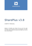
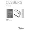
Operating instructions, mounting & installation TET Temperature controller for top hat rail installation with remote sensor S+S REGELTECHNIK GMBH | KLINGENHOFSTR. 11 | 90411 NUREMBERG | GERMANY | PHONE +49(0)911 ⁄ 51947-0 | FAX +49(0)911 ⁄ 51947-70 | www.S p lusS.eu | [email protected] Industry-oriented solutions – Complete control technology from one source! THERMASREG ® TET Temperature controller for top hat rail installation with remote sensor APPLICATION: For electronic control and monitoring of temperatures by remote sensor in the residential sector (e.g. floor heating systems), in halls and greenhouses and in the industrial sector. This controller features sensor breakage recognition and a switch-off function. TECHNICAL DATA: Power supply: ................................... 24 V AC ⁄ DC, 230 V AC, +10 % ⁄ -15 %, 50 - 60 Hz Control range: . ................................ -10 °C …+30 °C; 0 °C …+60 °C; +10 °C …+120 °C, selectable Input: . ................................................ Pt1000 Output: .............................................. relay as single-pole, potential-free changeover contact (1x) Switching capacity: . ........................ max. 6 A 250 V AC (Contact load) Ue ⁄ le AC-15, 120 V ⁄ 3.,5 A, 240 V ⁄ 3 A Ue ⁄ le DC-13, 24 V ⁄ 2.5 A EN 60947-5-1, VDE 0435 Operating difference: . .................... adjustable Lifetime: changeover contact mechanical: 5 x 10⁶ changeover contact electrical: 1 x 10⁵ Ambient conditions: ........................ -20 °C ...+60 °C, non-precipitating Operating mode indicator: ............. LED Enclosure: ......................................... plastic, colour black-grey (similar RAL 7021) and light grey (similar RAL 7035), width: 45 mm, 3TE Electrical connection: . ................... 0.14 - 2.5 mm2 via terminal screws Mounting: . ........................................ on DIN top hat rail Humidity: . ......................................... < 90 % r. H., non-precipitating air Protection class: . ............................ II (according to EN 60 730) Protection type: ............................... IP 20 at front side (according to IEC 529) Standards: ........................................ CE conformity, electromagnetic compatibility according to EN 61 326 + A1 + A2, EMC directive 89 ⁄ 336 ⁄ EWG, low-voltage directive 73 ⁄ 23 ⁄ EWG FUNCTION: The evaluation range is preset at the potentiometer on top. Three measuring ranges can be chosen: -10 °C …+30 °C; 0 °C …+60 °C; +10 °C …+120 °C. The temperature to be monitored is determined by the potentiometer »Setpoint« and the switchpoints (hysteresis) are defined at the potentiometer »Hyst.« When temperature at the Pt1000 exceeds the value of »Setpoint + Hyst.«, the output relay switches to rest position (switched off). When temperature falls below »Setpoint - Hyst.«, the output relay is reactivated. The following conditions result in a drop of the relay to rest position: Excess temperature, short circuit, or wire breakage at the Pt 1000 sensor, failure of power supply. Measuring input and power supply have no electric connection i.e. are electrically isolated. Type ⁄ WG 2 Supply voltage Input sensor Output TET 230V AC 230 V AC, 2.5 VA Pt 1000 1 x changeover contact (potential-free) TET 24V AC 24 V AC, 2.5 VA Pt 1000 1 x changeover contact (potential-free) TET 24V DC 24 V DC, 2.5 VA Pt 1000 1 x changeover contact (potential-free) TET TET Dimensional drawing Connecting diagram TET Scheme TET General notes Our “General Terms and Conditions for Business“ together with the “General Conditions for the Supply of Products and Services of the Electrical and Electronics Industry“ (ZVEI conditions) including supplementary clause “Extended Retention of Title“ apply as the exclusive terms and conditions“. Furthermore, the following points must be observed: - These instructions shall be read before installation and putting in operation and all directions contained herein shall be followed! - These devices must only be connected to safety extra-low voltage and under dead-voltage condition. To avoid damages and errors at the device (e.g. by voltage induction), shielded cables shall be used, laying parallel with current-carrying lines is to be avoided, and the EMC directives must be adhered to. - This device shall only be used for its intended purpose. Respective safety regulations issued by the VDE, the states, their control authorities, the TÜV and the local energy supply company must be observed. The buyer has to ensure adherence to the building and safety regulations and has to avoid all dangers of any kind. - We do not assume any warranties or liabilities for faults or damages arising or resulting from improper use of this device. - Consequential damages caused by a fault in this device are excluded from warranty or liability. - These devices must be installed by authorized qualified personnel only. - The technical data and connecting conditions shown in the mounting and operating instructions delivered together with the device are exclusively valid. Deviations from the catalogue representation are not explicitly mentioned and are possible in terms of technical progress and continuous improvement of our products. - In case of any modifications made by the user, all warranty claims are forfeited. - This device must not be installed close to heat sources (e.g. radiators) or be exposed to their heat flow. Direct sun irradiation or heat irradiation by similar sources (powerful lamps, halogen spotlights) must absolutely be avoided. - Operating this device close to other devices that do not comply with EMC directives may influence functionality. - This device must not be used for monitoring applications, which solely serve the purpose of protecting persons against hazards or injury, or as an EMERGENCY STOP switch for systems or machinery, or for any other similar safety-relevant purposes. - Dimensions of enclosures or enclosure accessories may show slight tolerances on the specifications provided in these instructions. - Modifications of these records are not permitted. - In case of a complaint, only complete devices returned in original packing will be accepted. © Copyright by S+S Regeltechnik GmbH · Reprints, in part or in total, are only permitted with the approval of S+S Regeltechnik GmbH. 1322 III ⁄ 08 These instructions must be read before installation and putting in operation and all notes provided therein are to be r egarded!