1
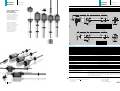
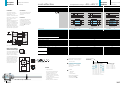
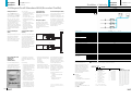
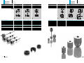
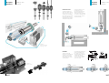
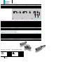
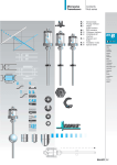
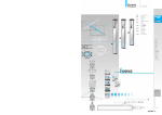
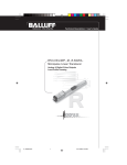
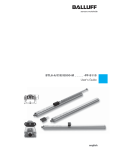
Micropulse
Transducer
Contents
Rod series
B.2
B.4
B.6
B.8
B.10
B.12
B.14
B.16
General data
Analog interface
Digital
pulse interface
SSD interface
CANopen interface
Magnets
and floats
Installation notes
Connectors
B
BTL
General
data
Analog
interface
Digital
pulse
interface
SSD
interface
CANopen
interface
Magnets
and
floats
Installation
notes
Connectors
B.1
Micropulse
Transducer
General data
Rod series
Micropulse
Transducer
General data
Rod series
BTL5 Rod-style
Series
Pressure rated to 600 bar,
high repeatability,
non-contact, rugged
Nominal stroke = Measuring area
The BTL Micropulse transducer is the rugged position
feedback system for use
under extreme ambient
conditions measuring
between 25 and 3850 mm.
Damping zone
(non-usable area)
Magnet
B
BTL
Thread
M4 x 6 deep
The actual waveguide is
protected inside a highpressure resistant stainless
steel tube. The system
is ideal for use in hydraulic
cylinders for position
feedback or as a level
monitor with aggressive
media in the food and
chemical industries.
General
data
Thread M18x1.5
Mounting surface
Interface
Analog
A, E, C, G
Digital
P, M, I
SSD
S
CANopen H
Nominal stroke = measuring area
A (mm)
74
57
74
85.5
B (mm)
69
69
69
73
C (mm)
48
48
48
51
Analog
interface
Digital
pulse
interface
SSD
interface
Damping zone
(non-usable area)
CANopen
interface
Magnets
and
floats
Magnet
Installation
notes
Thread
M4 x 6 deep
Connectors
Thread M18x1.5
Mounting surface
100 g/6 ms per IEC 68-2-27 and 100 g/2 ms per IEC 68-2-29
12 g, 10...2000 Hz per IEC 68-2-6
yes
Transzorb protection diodes
500 V (GND to housing)
IP 67 (when BKS-S32/33 is installed)
anodized aluminum/1.4571 stainless tube, 1.3952 stainless investment case flange
thread M18 × 1.5, 3/4"-16UNF on request
600 bar installed in hydraulic cylinder
connector or integral cable
BKS-S 32M/BKS-S 32M-C/BKS-S 33M/(CANopen: BKS-S 92M-00/S 93M-00)
Emissions tests:
RF emission
EN 55 011 Group 1, Class A
Noise immunity tests:
Static electricity (ESD)
Electromagnetic fields (RFI)
Fast transients (BURST)
Line-carried noise,
induced by high-frequency fields
▼
Standard nominal strokes [mm]
B.2
A (mm)
74
57
74
85.5
BTL5-...-M_ _ _ _ -B-_ _ _ _
Ordering code
Shock load
Vibration
Polarity reversal protected
Overvoltage protection
Dielectric strength
Enclosure rating per IEC 529
Housing material
Mounting
Pressure rating
Connection type
Recommended connectors see page B.16
Interface
Analog
A, E, C, G
Digital
P, M, I
SSD
S
CANopen H
IEC 1000-4-2 Severity Level 3
IEC 1000-4-3 Severity Level 3
IEC 1000-4-4 Severity Level 4
IEC 1000-4-6 Severity Level 3
0025, 0050, 0075, 0100, 0125, 0150,
0325, 0350, 0375, 0400, 0425, 0450,
0750, 0800, 0850, 0900, 0950, 1000,
1700, 1800, 1900, 2000, 2250, 2500,
or in 5 mm increments on request
Included:
– Transducer (see starting B.4 for interface options)
– Jam nut M18×1.5
– User's manual
0175,
0475,
1100,
2750,
0200,
0500,
1200,
3000,
0225,
0550,
1300,
3250,
Please order separately:
Magnets page B.12
Floats page B.13
Connectors page B.16
0250,
0600,
1400,
3500,
0275,
0650,
1500,
3750,
0300,
0700,
1600,
3850
B.3
Micropulse
Transducer
Analog interface
Rod series
100 % stroke adjustment
Series
Output signal
Transducer interface
Input interface
100 % Null- and endpoint
calibration
BTL5 Rod
analog
A
analog
BTL5 Rod
analog
E
analog
Micropulse
Transducer
Analog interface
Rod series
BTL5 Rod
analog
C
analog
BTL5 Rod
analog
G
analog
Calibration device 112774
Null and endpoint of the
analog signal can be buttonset to the desired position.
Depending on the application,
teach-in or adjust mode is
used, selectable by pressing
a button combination.
B
BTL
Sequence for teach-in,
rising output signal
General
data
Button inactive
before
after
1. Move magnet to new null
position.
Button active
Teach-in
Nullpoint
Endpoint
Endpoint
Cal mode selection
Ordering code
BTL5-A11-M_ _ _ _-B-_ _ _ _
Output voltage
Output current
Load current
max. ripple
Load resistance
System resolution
Adjust
Nullpoint
Analog
interface
Store new null value
2. Move magnet to new end
position.
BTL5-E1_-M_ _ _ _-B-_ _ _ _
4...20 mA or 20...4 mA
max. 5 mA
£ 5 mV
£ 0.33 mV
£ 500 Ohm
£ 0.66 µA
Store new end value
Adjust
B.4
Voltage output
Current output
Traverse velocity of magnet
Operating voltage
Current draw
Polarity reversal protected
Overvoltage protection
Dielectric constant
Operating temperature
Storage temperature
Pin assignments
Output signals
Pin
1
2
3
5
6
7
8
Supply voltage
Micropulse
BTL5-A/C/E/G...B features
max. 5 mA
£ 5 mV
£ 500 Ohm
£ 0.66 µA
£ 0.33 mV
Color
YE
GY
PK
GN
BU
BN
WH
BTL5-A11...
0 V output
10...0 V
0...10 V
GND
+24 V DC
(GND)
BTL5-E10...
BTL5-E17...
4...20 mA
20...4 mA
0 V output
GND
+24 V DC
(GND)
SSD
interface
CANopen
interface
Magnets
and
floats
Installation
notes
Connectors
BTL5-C10...
BTL5-C17...
0...20 mA
20...0 mA
0 V output
BTL5-G11...
0 V output
10...–10 V
–10 ... 10V
GND
+24 V DC
(GND)
GND
+24 V DC
(GND)
Please order separately:
Magnets page B.12
Connectors page B.16
▼
– Error signal:
Output signals above
or below the preset
values can be interpreted
and reported with an error
signal.
Example: no magnet in
measuring range or
start program mode.
Included:
– Transducer
– Jam nut
– Calibration device 112774
– User's manual
Please enter code for output
signal, nominal stroke and
connection type in ordering
code!
▼
Connect shield to housing.
– 100 % adjustment of
analog signal
– 2 calibration modes:
Teach-in and Adjust for null
and endpoint
– Electronics head can
be replaced if damaged
– Short housing
▼
Here you can adjust to a new
start and/or end value. This
may be required when you
cannot physically move the
magnet to the standard null
and/or endpoint.
Alternately move the magnet
to the new start and end
position, and adjust the
displayed value by pressing
the button until the desired
output values are reached.
0...20 mA or 20...0 mA
£ 5 µm
£ 10 µm (hysteresis + resolution)
fSTANDARD = 2 kHz
±100 µm to 500 mm nominal stroke
±0.02 % 500...3850 mm nominal stroke
[150 µV/°C + (5 ppm/°C × P × U/L)] × DT
[0.6 µA/°C + (10 ppm/°C × P × I/L)] × DT
any
24 V DC ±20 %
£ 150 mA
yes
Transzorb protection diodes
500 V (ground to housing)
–40...+85 °C
–40...+100 °C
Hysteresis
Repeatability
Internal sampling frequency
max. non-linearity
Temperature coefficient
3. New working range
BTL5-G11-M_ _ _ _-B-_ _ _ _
–10...10 V and 10...–10 V
Teach-in
You wish to replace the
factory set null and endpoint
with new values. First move
the magnet to the new null,
then to the new end position
and store their associated
value by pressing the button.
BTL5-C1_-M_ _ _ _-B-_ _ _ _
0...10 V and 10...0 V
Digital
pulse
interface
Preferred models
interface A11 and E10
BTL5-A11-M_ _ _ _-B-S 32,
BTL5-E10-M_ _ _ _-B-S 32
marked in blue are available
from stock.
Ordering example:
BTL5-E1_-M_ _ _ _-B-_ _ _ _
Output signal
1
0
7
increasing
and decreasing
(for A and G)
increasing
decreasing
(for C and E)
Standard
nominal strokes [mm]
0025, 0050, 0075, 0100, 0125,
0150, 0175, 0200, 0225, 0250,
0275, 0300, 0325, 0350, 0375,
0400, 0425, 0450, 0475, 0500,
0550, 0600, 0650, 0700, 0750,
0800, 0850, 0900, 0950, 1000,
1100, 1200, 1300, 1400, 1500,
1600, 1700, 1800, 1900, 2000,
2250, 2500, 2750, 3000, 3250,
3500, 3750, 3850 or in
5 mm increments on request.
Connection type
S 32
KA02
KA05
KA10
KA15
Connector
PU cable 2 m
PU cable 5 m
PU cable 10 m
PU cable 15 m
B.5
Micropulse
Transducer
Digital pulse interface
Rod series
cost-effective
Temperature range
Series
M-Interface
Compatible with BTA
processors and various
OEM controls, e. g.,
Siemens, Schleicher, B & R,
Mitsubishi, Schiele, Parker,
Esitron, Philips, Fanuc
and others.
Reliable signal transmission,
even over cable lengths
up to 500 m between BTA
and BTL, is assured by the
especially noise-immune
RS485 differential drivers
and receivers. Noise signals
are effectively suppressed.
The I- and M-interfaces are
control-specific interface
variations.
Digital pulse interface
Rod series
BTL5 Rod
BTL5 Rod
pulse P
pulse P
pulse M
pulse M
pulse I
pulse I
I-Interface
B
BTL
Used for parallel operation
of multiple transducers,
for example up to 4 transducers can be operated by
a single BTA-M/PMT card
(see page A.2 in Profile
brochure).
General
data
Analog
interface
Ordering code
BTL5-P1-M_ _ _ _-B-_ _ _ _
System resolution
Repeatability
Resolution
Hysteresis
Internal sampling rate
max. non-linearity
Block diagram for P-Interface
Pin assignments
Input/output signals
Highly precise digitizing
of the P-interface signal
Supply voltage
Companies developing their
own control and processing
44QFP digitizing chip
electronics can create a
highly accurate P-interface
cost effectively and with a
minimum of effort using the
Osz.
5V
Balluff digitizing chip. The
digitizing chip was deveSSD
loped as a high-resolution,
configurable ASIC for the
Micropulse P-interface.
Pin
1
2
3
5
6
7
8
Color
YE
GY
PK
GN
BU
BN
WH
BTL5-P1-M...
INIT
START/STOP
INIT
START/STOP
GND
+24 V DC
(GND)
BTL5-I1-M_ _ _ _-B-_ _ _ _
Digital
pulse
interface
SSD
Interface
CANopen
interface
Magnets
and floats
Installation
notes
Connectors
BTL5-M1-M...
INIT
START/STOP
INIT
START/STOP
GND
+24 V DC
(GND)
BTL5-I1-M...
INIT
START/STOP
INIT
START/STOP
GND
+24 V DC
(GND)
▼
Micropulse transducer
with 1 to 4 magnets
Please enter code for nominal
stroke and connection type in
ordering code!
▼
Shield connected to housing.
Preferred P-interface models
BTL5-P1-M_ _ _ _-B-S 32
marked in blue are available
from stock.
INIT
CPUcontroller
Benefits
P pulse output
Controller or
processing electronics
ASIC INFO: +49 (0) 71 58/1 73-2 66
– High resolution:
the 2 µm actual resolution of
the BTL transducer is fully
supported by the 5 µm
resolution of the chip (at low
clock frequency 2 or 20 MHz)
– Position data from
4 magnets can be processed
simultaneously
– 4/8-bit processor interface
▼
4/8 Bit-Bus
Input
Output
Input
Output
BTL5-M1-M_ _ _ _-B-_ _ _ _
processing-dependent
£ 6 µm (hysteresis + resolution)
£ 2 µm
£ 4 µm
fSTANDARD = 1 kHz = £ 1400 mm
±100 µm to 500 mm nominal stroke
±0.02 % 500...3850 mm nominal stroke
(6 µm +5 ppm × L)/°C
any
24 V DC ±20 %
£ 100 mA
–40...+85 °C
–40...+100 °C
Temperature coefficient of the overall system
Traverse velocity of magnet
Operating voltage
Current draw
Operating temperature
Storage temperature
B.6
Micropulse
Transducer
BTL5 Rod
Transducer interface
User interface
P-Interface
-40...+85 °C
Included:
– Transducer
– Jam nut
– User's manual
Ordering example:
BTL5-P1-M_ _ _ _-B-_ _ _ _
Standard
nominal strokes [mm]
0025, 0050, 0075, 0100, 0125,
0150, 0175, 0200, 0225, 0250,
0275, 0300, 0325, 0350, 0375,
0400, 0425, 0450, 0475, 0500,
0550, 0600, 0650, 0700, 0750,
0800, 0850, 0900, 0950, 1000,
1100, 1200, 1300, 1400, 1500,
1600, 1700, 1800, 1900, 2000,
2250, 2500, 2750, 3000, 3250,
3500, 3750, 3850 or in
5 mm increments on request.
Connection type
S 32
KA02
KA05
KA10
KA15
Connectors
PU cable 2 m
PU cable 5 m
PU cable 10 m
PU cable 15 m
Please order separately:
Magnets page B.12
Connectors page B.16
B.7
Micropulse
Transducer
SSD interface
Rod series
super linear
Series
Output signal
Transducer interface
User interface
SSD Interface
Synchronous serial data
transmission for controls
made by Siemens,
Schleicher, B & R, Mitsubishi,
Schiele, Parker, Esitron,
Philips, Fanuc etc. as well as
for Balluff BDD-AM10-1-SSD
display/controller with two
relay outputs.
Micropulse
Transducer
SSD interface
Rod series
BTL5 Rod
synchronous-serial
S
synchronous-serial
Reliable signal transmission,
even over cable lengths of up
to 400 m between control
and BTL transducer is
assured by especially
noise-immune RS485/422
differential line drivers and
receivers. Any noise signals
are effectively suppressed.
B
BTL
Pulse sequence
General
data
Analog
interface
Ordering code
Transducer
BTL5-S1...
Processor
or
controller
BTL5-S1... with processor/controller, wiring example
Pin assignments
Control and data
signals
Clock frequency
depends on cable length
Clock frequ.
< 1000 kHz
< 500 kHz
< 400 kHz
< 200 kHz
< 100 kHz
Supply voltage
(external)
▼
Cable length
< 25 m
< 50 m
< 100 m
< 200 m
< 400 m
BTL5-S1_ _-M_ _ _ _-B-S 32
£ 2 Digit (hysteresis + system resolution)
5, 10, 20 or 40 µm
£ 1 Digit
fSTANDARD = 2 kHz
±30 µm for 5 and 10 µm resolution or £ ±2 LSB
(6 µm +5 ppm × L) /°C
100 g/6 ms per IEC 68-2-27 and 100 g/2 ms per IEC 68-2-29
12 g, 10...2000 Hz per IEC 68-2-6
any
24 V DC ±20 %
£ 80 mA
–20...+85 °C
–20...+100 °C
Repeatability
System resolution depending on version (LSB)
Hysteresis
Internal sampling rate
max. non-linearity
Temperature coefficient of the overall system
Shock loading
Vibration
Traverse velocity of magnet
Operating voltage
Current draw
Operating temperature
Storage temperature
Pin
1
2
3
5
6
7
8
Color
YE
GY
PK
GN
BU
BN
WH
Digital
pulse
interface
SSD
interface
CANopen
interface
Magnets
and
floats
Installation
notes
Connectors
+Clk
+Data
–Clk
–Data
GND
+24 V DC
must remain unconnected
Please enter code for coding, system resolution,
nominal stroke and connection type when ordering!
Ordering example:
BTL5-S1_ _-M_ _ _ _-B-_ _ _ _
Super-fast 2 kHz Sampling rate
Coding
▼
0
1
6
7
Binary increasing (24 bits)
Gray increasing (24 bits)
Binary increasing (25 bits)
Gray increasing (25 bits)
Included:
– Transducer
– Jam nut
– User's manual
Please order separately:
Magnets page B.12
Floats page B.13
Connectors page B.16
B.8
System
resolution
2
3
4
5
5
10
20
40
µm
µm
µm
µm
Standard
nominal strokes [mm]
0025, 0050, 0075, 0100,
0125, 0150, 0175, 0200,
0225, 0250, 0275, 0300,
0325, 0350, 0375, 0400,
0425, 0450, 0475, 0500,
0550, 0600, 0650, 0700,
0750, 0800, 0850, 0900,
0950, 1000, 1100, 1200,
1300, 1400, 1500, 1600,
1700, 1800, 1900, 2000,
2250, 2500, 2750, 3000,
3250, 3500, 3750, 3850
or in 5 mm increments
on request.
Connection type
S 32
KA02
KA05
KA10
KA15
Connector
PU cable 2 m
PU cable 5 m
PU cable 10 m
PU cable 15 m
B.9
Micropulse
Transducer
CANopen interface
Rod series
Position + Velocity
Series
Output signal
Transducer interface
User interface
CANopen Draft Standard 406 (Encoder Profile)
CANopen Interface
The CANopen interface of
the Micropulse transducer is
compatible with CANopen
per CiA Standard DS-301
Rev. 3.0, CAL and Layer 2
CAN networks. There are
2 versions depending on the
data arrangement in the
object directory: Object
directory per Draft Standard
406 (Encoder Profile DS406)
and manufacturer-specific
to Balluff standard (Balluff
Profile).
You can send:
– the current position of the
magnet with resolution
selectable for 5, 10, 20,
50 and 100 µm
– the current velocity of the
magnet with resolution
selectable for 0.1, 0.5 and
1 mm/s
– the current status of
four free programmable
setpoints (cams)
– the position and the
velocity format integer
32/16 with selectable
resolution
Cam-dependent
transmission rate
Active cams can be used to
program high, cyclical data
transmission.
Emergency Object
Emergency Object means:
transmitting data with the
highest priority. This is used
for example for error
messages when cam states
change.
Micropulse
Transducer
CANopen interface
Rod series
BTL5 Rod-style
CANopen
H
CANopen
Service Data Object (SDO)
Service Data Objects transmit
the parameters for the
transducer configuration. The
transducer configuration may
be carried out on the bus by
the controller, or offline using
a PC with a configuration tool
which runs under Windows.
The configuration is stored in
the transducer in a nonvolatile memory.
B
BTL
General
data
Analog
interface
Digital
pulse
interface
Termination
Process Data Object
(PDO)
Micropulse transducers send
their position information
optionally in one or two
PDOs with 8 bytes of data
each. The contents of the
PDOs is free configurable.
Ordering code
Synchronisation Object
(SYNC)
Serves as a net-wide trigger
for synchronizing all network
participants. When the
SYNC object is received, all
Micropulse transducers
active on the bus store their
current position and velocity
information and then send it
sequentially to the control.
This assures timesynchronous capture of the
measured values.
Node n
BTL5-H1_ _-M_ _ _ _-B-S 92
CANopen interface
Repeatability
System resolution
Position
configurable
Velocity
Hysteresis
Internal sampling rate
max. non-linearity
Temperature coefficient of the overall system
Traverse velocity of magnet
Operating voltage
Current draw
Operating temperature
Storage temperature
Transducer
BTL5-H11...
Node m
Controller/
Master
Cable length [m] per CiA DS 301
Baud rate [kBaud] per CiA DS 301
B.10
or for reading out the BTL
parameters and LMT data.
Runs under Windows 3.11 or
higher.
is a user-friendly software
for parameterizing the BTL
and for mapping the BTL
data in the PDOs. It can also
be used for test purposes
Functionality:
– Menu-driven configuration
of all manufacturer-specific
module parameters and
module-specific communications parameters.
Checking entries for valid
values.
– LMT data, consisting of:
manufacturer's name
(7 characters), product
name (7 characters) and
serial no. (14 characters).
– Node-ID and baud rate.
– Setting the working range
and cam switchpoints.
The parameters can also
be configured in teach-in
mode, whereby the resp.
current position is read in
by the configuration tool.
– Operating mode selection
for sending and preparing
BTL data:
continuous,
on-demand,
event-triggered.
– Arrangement of the BTL
data (position, velocity and
status) in the data field of
the PDO (object mapping).
The configuration entered is
sent to the BTL module and
there stored in the object
directory. At the same time,
the object directory is stored
in the configuration tool.
The configuration parameters, which are stored in
a database, can for example
be copied from one module
to another (e. g., when
replacing modules).
CAN-Bus-Interface on a PC:
1. CANdy*
Connects to the parallel
interface
2. PCI-302*
Plug-in card with bus
analyzer function
*Products of Steinbeis Transferzentrums Prozessautomatisierung
Weingarten.
Pin
1
2
3
4
5
Using the CANopen interface
and cable lengths up to
2500 m, the signal is sent at a
length-dependent baud rate
to the control. The high noise
immunity of the connection is
achieved using differential
drivers and by the data monitoring scheme implemented in
the data protocol.
▼
BTL Configuration Tool
CANopen for
BTL5-H10_-...
(Balluff Profile)
Pin assignments
Control and
data signals
Included:
– Transducer
– Jam nut
– User's manual
– Configuration and CAN interface
Please order separately:
Magnets page B.12
Floats page B.13
Connectors BKS-S92/BKS-S93
page B.16
< 25
1000
< 50
800
< 100
500
< 250
250
Color
WH
BN
BU
GY
GN
▼
Termination
SSD
interface
potential-free
£ 2 digit (hysteresis + system resolution)
5, 10, 20, 50 and 100 µm
0.1 mm/s, 0.5 mm/s, 1 mm/s
£ 1 digit
fSTANDARD = 2 kHz
±30 µm at 5 µm resolution
(6 µm +5 ppm × L)/°C
any
24 V DC ±20 %
£ 100 mA
–20...+85 °C
–20...+100 °C
< 500 < 1000 < 1250
125
100
50
CANopen
interface
Magnets
and
floats
Installation
notes
Connectors
< 2500
20/10
CAN_GND
+24 V
0 V (GND)
CAN_HIGH
CAN_LOW
Please enter code for software configuration, baud rate and
nominal length when ordering! Cable upon request.
Ordering example:
BTL5-H1_ _-M_ _ _ _-B-S 92
Software
configuration
0
1
2
3
1 × position and
1 × velocity
OV per Balluff Profile
1 × position and
1 × velocity
OD per DS 406
2 × position and
2 × velocity
OD per DS 406
4 × position
OD per DS 406
OD = Object Directory
DS406 = Encoder Profile
Baud
rate
0
1
2
3
4
5
6
7
8
1
800
500
250
125
100
50
20
10
Standard
nominal strokes [mm]
MBaud
kBaud
kBaud
kBaud
kBaud
kBaud
kBaud
kBaud
kBaud
0025, 0050, 0075, 0100,
0125, 0150, 0175, 0200,
0225, 0250, 0275, 0300,
0325, 0350, 0375, 0400,
0425, 0450, 0475, 0500,
0550, 0600, 0650, 0700,
0750, 0800, 0850, 0900,
0950, 1000, 1100, 1200,
1300, 1400, 1500, 1600,
1700, 1800, 1900, 2000,
2250, 2500, 2750, 3000,
3250, 3500, 3750, 3850
or in 5 mm increments
on request.
B.11
Micropulse
Transducer
Magnets
Rod series
Name
for series
Micropulse
Transducer
Magnet
BTL5 Rod
Magnet
BTL5 Rod
Magnet
BTL5 Rod
Name
for series
Float
BTL5 Rod
Float
BTL5 Rod
Floats
Rod series
Floats
BTL5 Rod
B
BTL
General
data
Analog
interface
Ordering code aluminum
Material
Weight
Traverse velocity of magnet
Operating temperature/storage temperature
Ordering code PA 60 fiberglass reinforced
Material
Weight
Traverse velocity of magnet
Operating temperature/storage temperature
B.12
BTL-P-1013-4R
BTL-P-1013-4S
BTL-P-1012-4R
aluminum
ca. 12 g
any
–40...+100 °C
aluminum
ca. 12 g
any
–40...+100 °C
aluminum
ca. 12 g
any
–40...+100 °C
BTL-P-1013-4R-PA
BTL-P-1012-4R-PA
PA 60 fiberglass reinforced
ca. 10 g
any
–40...+100 °C
PA 60 fiberglass reinforced
ca. 9 g
any
–40...+100 °C
Ordering code
BTL2-S-3212-4Z
BTL2-S-4414-4Z
BTL2-S-6216-8P
Material
Weight
Traverse velocity of magnet
Operating/storage temp.
Submersion depth in water
Pressure rating
1.4571 stainless
ca. 20 g
any
–40...+120 °C
35 mm
24 bar
1.4571 stainless
ca. 35 g
any
–40...+120 °C
31 mm
20 bar
1.4571 stainless
ca. 66 g
any
–40...+120 °C
41 mm
15 bar
Digital
pulse
interface
SSD
interface
CANopen
interface
Magnets
and
floats
Installation
notes
Connectors
B.13
Micropulse
Transducer
Installation notes
Rod series
Micropulse
Transducer
Hassle-free service
Cylinder-mounted transducers are often located in
difficult to access spots. If
a transducer is damaged or
fails, replacing the complete
transducer with head and
waveguide is often a difficult
and expensive proposition.
Installation notes
Rod series
Should a problem occur in
the electronics of the
Micropulse transducer, the
electronics head can be
easily and quickly exchanged
for a new one. The fluid circuit
also remains intact, with no
draining necessary.
B
BTL
General
data
Analog
interface
Digital
pulse
interface
SSD
interface
CANopen
interface
Magnets
and
floats
Installation
notes
Servicing a vertical installation
Connectors
Application:
Hydraulic cylinder with
closed-loop control
Servicing a horizontal installation
Installation
The BTL Micropulse
transducer is provided with
an M18 × 1.5 mounting
thread. We recommend
mounting into non-magnetizable materials.
If magnetizable materials are
used, the installation must
be carried out as shown in
the drawing below. Sealing is
at the flange mounting
surface, using the supplied
O-ring 15.4 × 2.1 with the
M18 x 1.5 thread.
O-ring groove
Threaded port
to ISO 6149
Installation in
hydraulic cylinders
Magnet
Non-magnetizable spacer
B.14
B.15
Micropulse
Transducer
Connectors
for series
Version
Ordering code
Connectors
BKS-S 32M
BTL5
BKS-S 32M-C
BTL5
BKS-S 33M
BTL5
straight
straight
right-angle
BKS-S 32M-_ _
BKS-S 32M-C-00
BKS-S 33M-_ _
max. 0.5 mm²
Crimp contacts
max. 0.75 mm2
Solder connection
Housing material
CuZn, nickel plated
Contact
CuSn
Contact surface
0.8 µm Au
Cable strain relief
PG 9
min. cable diameter
6...8 mm
Cable
Lif2Y-FC-11Y- 0
No. of conductors × cross-section
7 × 0.25 mm²
Enclosure rating per IEC 529
IP 67 (when connected)
Please indicate cable length in ordering code!
Code 00 for unassembled (use shielded cable).
Code 05, 10, 15, 20, 25 30 m for finished assembled cable.
CuZn, nickel plated
CuSn
0.8 µm Au
PG 9
6...8 mm
IP 65 (when connected)
Connectors for Micropulse with CANopen Interface
Ordering code
BKS-S 92M-00
BKS-S 93M-00
Screw terminal
max. 0.75 mm2
Housing material
CuZn, nickel plated
Contact
CuSn
Contact surface
0.8 µm Au
Cable strain relief
PG 9
min. cable diameter
6...8 mm
Enclosure rating per IEC 529
IP 67 (when connected)
BKS-S 92/BKS-S 93 compatible, shielded plastic connectors
with molded cable available on request.
max. 0.75 mm2
CuZn, nickel plated
CuSn
0.8 µm Au
PG 9
6...8 mm
IP 67 (when connected)
BKS-S 32M-_ _/BKS-S 33M-_ _
BKS-S 92M-00/BKS-S 93M-00
Pin assignments
Pin assignments
View of female
solder side
B.16
Pin
1
2
3
5
6
7
8
Color
YE
GY
PK
GN
BU
BN
WH
View of female
screw side
Pin
1
2
3
4
5
max. 0.75 mm2
ZnAlCu1, nickel plated
CuSn
0.8 µm Au
PG 9
6...8 mm
Lif2Y-FC-11Y- 0
7 × 0.25 mm²
IP 67 (when connected)
Signal
CAN_GND
+24 V
GND (0 V)
CAN_HIGH
CAN_LOW