1
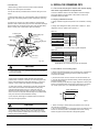
INSTALLATION MANUAL
Four-way Cassette Type
Digital Scroll and DC/AC Inverter Commercial Air-conditioner
The Digital Scroll and DC/AC Inverter share the same indoor units.
Thank you very much for purchasing our air conditioner,
please read this manual carefully and keep it for future reference.
CONTENTS
PAGE
1. PRECAUTIONS....................................................................................1
2. INSTALLATION INFORMATION........................................................... 2
3. ATTACHED FITTINGS..........................................................................3
4.INSTALLATION.....................................................................................4
5. LAYOUT THE DRAIN PIPE.................................................................10
6. INSTALL THE CONNECTING PIPE......................................................11
7. WIRING.............................................................................................13
8. CONTROL OPERATION......................................................................15
9. TEST PERATION................................................................................17
Install according to this installation instructions strictly.
If installation is defective, it will cause water leakage,
electrical shock fire.
When installing the unit in a small room, take measures
against to keep refrigerant concentration from exceeding
allowable safety limits in the event of refrigerant leakage.
Contact the place of purchase for more information.
Excessive refrigerant in a closed ambient can lead to oxygen
deficiency.
Use the attached accessories parts and specified parts
for installation.
Otherwise, it will cause the set to fall, water leakage,
electrical shock fire.
Install at a strong and firm location which is able to
withstand the set's weight.
If the strength is not enough or installation is not properly
done, the set will drop to cause injury.
The appliance must be installed 2.3m above floor.
The appliance shall not be installed in the laundry.
1.
PRECAUTIONS
Be sure to be in conformity with the local, national and
international laws and regulations.
Read "PRECAUTIONS" carefully before installation.
The following precautions include important safety items.
Observe them and never forget.
Keep this manual with the owner's manual in a handy
place for future reference.
The safety precautions listed here are divided into two categories. In
either case, important safety information is listed which must be
read carefully.
WARNING
Failure to observe a warning may result in death.
CAUTION
Failure to observe a caution may result in injury or
damage to the equipment.
After completing the installation, make sure that the unit operates
properly during the start-up operation. Please instruct the customer
on how to operate the unit and keep it maintained.Also, inform
customers that they should store this installation manual along with
the owner's manual for future reference.
Before obtaining access to terminals, all supply circuits
must be disconnected.
The appliance must be positioned so that the plug is
accessible.
The enclosure of the appliance shall be marked by word,
or by symbols, with the direction of the fluid flow.
For electrical work, follow the local national wiring
standard, regulation and this installation instructions. An
independent circuit and single outlet must be used.
If electrical circuit capacity is not enough or defect in
electrical work, it will cause electrical shock fire.
Use the specified cable and connect tightly and clamp
the cable so that no external force will be acted on the
terminal.
If connection or fixing is not perfect, it will cause heat-up or
fire at the connection.
Wiring routing must be properly arranged so that control
board cover is fixed properly.
If control board cover is not fixed perfectly, it will cause
heat-up at connection point of terminal, fire or electrical
shock.
If the supply cord is damaged, it must be replaced by the
manufacture or its service agent or similarly qualified
person in order to avoid a hazard.
An all-pole disconnection switch having a contract
separation of at least 3mm in a poles should be
connected in fixed wiring.
WARNING
Be sure only trained and qualified service personnel to install,
repair or service the equipment.
Improper installation, repair, and maintenance may result in electric
shocks, short-circuit, leaks, fire or other damage to the equipment.
installation manual
1
When carrying out piping connection, take care not to let air
substances go into refrigeration cycle.
Otherwise, it will cause lower capacity, abnormal high pressure in
the refrigeration cycle, explosion and injury.
There is strong electromagnetic wave existing.
Do not modify the length of the power supply cord or use of
extension cord, and do not share the single outlet with other
electrical appliances.
Otherwise, it will cause fire or electrical shock.
Other special conditions.
Carry out the specified installation work after taking into
account strong winds, typhoons or earthquakes.
Improper installation work may result in the equipment falling and
causing accidents.
If the refrigerant leaks during installation, ventilate the area
immediately.
Toxic gas may be produced if the refrigerant comes into the place
contacting with fire.
After completing the installation work, check that the
refrigerant does not leak.
Toxic gas may be produced if the refrigerant leaks into the room
and comes into contact with a source of fire, such as a fan heater,
stove or cooker.
There are inflammable materials or gas.
There is acid or alkaline liquid evaporating.
2.
INSTALLATION INFORMATION
To install properly, please read this "installation manual"
at first.
The air conditioner must be installed by qualified persons.
When installing the indoor unit or its tubing, please follow
this manual as strictly as possible.
If the air conditioner is installed on a metal part of the
building, it must be electrically insulated according to the
relevant standards to electrical appliances.
CAUTION
Ground the air conditioner.
Do not connect the ground wire to gas or water pipes, lightning rod
or a telephone ground wire.Incomplete grounding may result in
electric shocks.
When all the installation work is finished, please turn on
the power only after a thorough check.
Regret for no further announcement if there is any change
of this manual caused by product improvement.
Be sure to install an earth leakage breaker.
Failure to install an earth leakage breaker may result in electric
shocks.
Connect the outdoor unit wires , then connect the indoor unit
wires.
You are not allow to connect the air conditioner with the power
source until wiring and piping the air conditioner is done.
While following the instructions in this installation manual,
install drain piping in order to ensure proper drainage and
insulate piping in order to prevent condensation.
Improper drain piping may result in water leakage and property
damage.
Install the indoor and outdoor units, power supply wiring and
connecting wires at least 1 meter away from televisions or
radios in order to prevent image interference or noise.
Depending on the radio waves, a distance of 1 meter may not be
sufficient enough to eliminate the noise.
The appliance is not intended for use by young children or
infirm persons without supervision.
Young children should be supervised to ensure that they do
not play with the appliance.
Don't install the air conditioner in the following locations:
There is petrolatum existing.
There is salty air surrounding (near the coast).
There is caustic gas (the sulfide, for example) existing in the air
(near a hot spring).
The volt vibrates violently (in the factories).
In buses or cabinets.
In kitchen where it is full of oil gas.
The appliance shall not be installed in the laundry.
installation manual
2
INSTALLATION ORDER
Select the location;
Install the indoor unit;
Install the outdoor unit;
Install the connecting pipe ;
Connect the drain pipe;
Wiring;
Test operation.
3.
ATTACHED FITTINGS
Please check whether the following fittings are of full scope. If there are some spare fittings , please restore them carefully.
Table: 3-1
NAME
INSTALLATION FITTINGS
QUANTITY
1. Expansible hook
4
2. Installation hook
4
3. Installation paper board
4. Bolt M6
5.Electric throttle
(That have been installed at the unit)
Tubing & Fittings
SHAPE
1
4
1
6. Connective pipe for
restriction assembly
1
7. Soundproof / insulation sheath
2
8. Out-let pipe sheath
1
9. Out-let pipe clasp
1
10. Tightening band
20
Drainpipe Fittings
11.Flexible hose tube
Signal line
1
12.Signal line
1
13. Remote controller
1
14. Frame
1
15. Alkaline dry batteries (AM4)
2
16. Remote contronller
owner's manual
1
17. Installation manual
1
Remote controller & Its Frame
Others
18. Network matching wire
(The indoor unit which at the terminal of communication system
should connect a impedance between port P an-d port Q.)
1
installation manual
3
4.1 Installation place
>1000mm
(Refer to Fig. 4-1, Fig. 4-2, Fig. 4-3 and Table: 4-1 for specification.)
>1000mm
4. INSTALLATION
The indoor unit should be installed in a location that meets
the following reauirements:
There is enough room for installation and maintenance.
The outlet and the inlet are not impeded, and the
influence of external air is the least.
The air flow can reach throughout the room.
>1000mm
The ceiling is horizontal, and its structure can endure the
weight of the indoor unit.
>1000mm
The connecting pipe and drainpipe could be extracted out
easily.
There is no direct radiation from heaters.
Fig. 4-2
CAUTION
4.2 Air supply direction
Installing the equipment in any of the following places may lead to
faults of the equipment (if that is inevitable, consult the supplier):
To select the following air supply directions base on your room
sharp and the unit installed site:
A. The site contains mineral oils such as cutting lubricant.
B. Seaside where the air contains much salt.
C. Hotpring area where corrosive gases exist, e.g., sulfide gas.
D. Factories where the supply voltage fluctuates seriously.
E. Inside a car or cabin.
F. Place like kitchen where oil permeates.
G. Place where strong electromagnetic waves exist.
H. Place where flammable gases or materials exist.
I. Place where acid or alkali gases evaporate.
J. Other special environments.
Connective port of
refrigerant pipe
Connet to the outlet
of drain pipe
(Air side)
A
H
Connective port
of refrigerant pipe
(Liquid side)
Fig. 4-3
1. Once changing the air supply direction, please replace the
wind shield materials. For details of wind shield materials please
consult our dealer.
2. Such as the above figure of air supply direction, before install
wind shield material, please remove the panel firstly, and then
insert the wing shield panel into air outlet of main body.
>2500mm
Ceiling
Air outlet
Air inlet
Air outlet
Panel
Main body
880 mm (Ceiling hole)
Wind shield panel
Floor
Fig. 4-4
Fig. 4-1
3. As for operating the electric heater and additional purchased
humidifier at the same time, to be on safe side, don’t alter the air
supply direction, and shall employ four-way air supply type to
operation.
Table: 4-1
Indoor unit
A(mm)
H(mm)
≤8000W
230
≥260
≥9000W
300
≥330
installation manual
4
WARNING
Install the unit at a site with sufficient strength to supporting the
weight of the unit.
Insufficient supporting strength would fall-down the unit and cause
human physical injury.
Special installation to prevent the unit be blown down by strong
wind and be shocked by earthquake. Failure installation would
cause fall-down accident.
3 Refer to 3 above for installation.
4 Remove the installation paper board.
Unit body
Central hole
4.3 Install the main body
The existing ceiling (to be horizontal)
1
Screw M6×12
(Accessories)
Install the paper board
Cut a quadrangular hole of 880x880mm in the ceiling according
to the shape of the installation paper board.
(refer to Fig. 4-4, Fig. 4-6 and Fig. 4-7)
Fig. 4-5
The center of the hole should be at the same position of that
of the air conditioner body.
Determine the lengths and outlets of the connecting pipe,
drainpipe and cables.
To balance the ceiling and to avoid vibration, please enforce
the ceiling when necessary.
2
Select the position of installation hooks according to the hook
holes on the installation board.
Drill four holes of
12mm, 45~50mm deep at the selected
positions on the ceiling. Then embed the expansible hooks
(fittings).
Face the concave side of the installation hooks toward the
expansible hooks. Determine the length of the installation
hooks from the height of ceiling, then cut off the unnecessary
part.
If the ceiling is extremely high, please determine the length of
the installation hook according to facts.
3
CAUTION
Before install the indoor unit, please remove the buffer between
in fan and flared mouth firstly. Otherwise, running operation
would damage the fan motor (See Fig. 4-6).
Ensure that the indoor unit is placed horizontally.
During connect the electrical restriction assembly to pipes of
indoor and outdoor units, please wrench it by two spanners to
avoid pipe be cracked.
The length of U-shaped lugs that come from the throttle
cabinet should be adjusted to the proper position while piping
Adjust the hexangular nuts on the four installation hooks
evenly, to ensure the balance of the body.
If the drainpipe is awry, leakage will be caused by the
malfunction of the water-level switch.
Adjust the position to ensure the gaps between the body and
the four sides of ceiling are even. The body's lower part
should sink into the ceiling for 10~12 mm (refer to Fig. 4-9).
Locate the air conditioner firmly by wrenching the nuts after
having adjusted the body's position well.(refer to Fig. 4-10)
New built houses and ceilings
1 In the case of new built house, the hook can be embedded in
advance (refer to 2 mentioned above). But it should be strong
enough to bear the indoor unit and will not become loose
because of concrete shrinking.
2 After installing the body, please fasten the installation paper
board onto the air conditioner with bolts(M6X12) to determine in
advance the sizes and positions of the hole opening on
ceiling.(refer to Fig. 4-5)
Please first guarantee the flatness and horizontal of ceiling when
installing it.
Fig. 4-6
Refer to 1 mentioned above for others.
installation manual
5
FIGURES
The connective pipe
of restricted assembly
(accessories)
950
780
55
680
950
Drain pipe outter diameter
Φ75New air
supply orifice
Fig. 4-7
≥20
Install hanger
Ceiling
146
Hexagon nut
(For adjust to balance)
46
Panel
Main body
Drain pipe
Electrical restricting assembly
Fig. 4-8
Fig. 4-9
Table: 4-2
10~12mm
L
Main body of the unit
Indoor unit model
A(mm)
B(mm)
≤8000W
230
170
≥9000W
300
190
Ceiling
Fig. 4-10
Fig. 4-11
NOTE
All the pictures in this manual are for explanation purpose only. They may be slightly different from the air conditioner you
purchased(depend on model).The actual shape shall prevail.
installation manual
6
4.4 Procedure of installing the pendant bolt
Base on the unit structure, please set the screw-pitch according to
the size of the following figures:
Table: 4-3
Wooden
Wooden
structure
structure
Put rectangular sticks across the beams, and set pendant bolts.
Wooden span
CAUTION
The bolt material is the high quality carbon steel (galvanized or
covered other rust preventive materials on the surface) or
rustless steel.
The ceiling rust prevention measure is conducted according to
actual construction, for detail method please consult building
engineer.
Suspending bolts must be fixed, the fixing method as per to the
actual situation.
4.5 Install the panel
Beam
Ceiling
CAUTION
Never put the panel face down on floor or against the wall,
or on bulgy objects.
Never crash or strike it.
Pendant bolt
1. Remove the air-in grill.
Old concrete roughcast
Use embedded bolts and embedded pulling plugs.
1) Slide two grill switches toward the middle at the same
time, and then pull them up. (Refer to Fig.4-12)
Grid switch
Fig.4-12
Table: 4-4
2) Draw the grill up to an angle of about 45, and remove it.
(Refer to Fig.4-13)
Steel beam and girder structure
Set and use supportive angle steel.
45°
Suspended bolt
Pendant bolt
Supportive angle steel
Fig.4-13
2. Remove the installation covers at the four corners.
Wrench off the bolts, loose the rope of the installation covers,
and remove them. (Refer to Fig.4-14)
New concrete roughcast
Set it with embedded bushes or embedded bolts.
Concrete iron
Flap type inser
Slide type inser
Embedded bolt
(With embedded
bolt in pipe)
fig.4-14
installation manual
7
3. Install the panel
1) The part of panel that marked “PIPING SIDE” and “DRAIN SIDE”
shall be aligned to piping outlet and drainpipe outlet from main body.
2) Fix hooks of the panel at swing motor and its opposite sides to the
hooks of corresponding water receiver. (Refer to Fig.4-15 a) Then
hang the other two panel hooks onto corresponding hangers of the
body. (Refer to Fig.4-15 b)
3) Insert the conducting wire of sway motor into the conducting slot
inside of panel, and then connect the sway motor terminals holder to
the terminal in main electrical control box.
CAUTION
1) The salient of plastic cap in sway motor shall be inserted in the
notch of the water outflow pipe seal board.
2) Do not coil the wiring of the swing motor into the seal sponge.
3) Malfunction described in Fig.4-17 can be caused by
inappropriate tightness the screw.
4) Adjust the four panel hook screws to keep the panel horizontal,
and screw them up to the ceiling evenly. (Refer to Fig.4-15 c)
5) Regulate the panel in the direction of the arrow in fig.4-14 d
slightly to fit the panel's center to the center of the ceiling's opening.
Guarantee that hooks of four corners are fixed well.
6) Keep fastening the screws under the panel hooks, until the
thickness of the sponge between the body and the panel's outlet has
been reduced to about 4~6mm. The edge of the panel should
contact with the ceiling well. (Refer to Fig.4-16)
Water receiver hook
Panel hook
Piping joint
Leakage
Ceiling
Pollution
Water condensation
Fig.4-17
4) If the gap between the panel and ceiling still exists after
fastening the screws, the height of the indoor unit should be
modified again. ( Refer to Fig.4-18)
a
Drain pipe joint
b
Gap not allowed
Sway motor
Fig.4-18
c
Hook-bolt
d
5) You can modify the height of the indoor unit through the
openings on the panel's four corners, if the lift of the indoor unit
and the drainpipe is not influenced (refer to Fig.4-19).
Cross-screwdriver
Loosen upper nut
Sway motor
Fig.4-15
Adjust lower nut
body
outlet foam
4 - 6mm
Ceiling
panel sponge
panel
panel foam1
Fig.4-19
4. Hang the air-in grill to the panel, then connect the lead
terminator of the swing motor and that of the control box
with corresponding terminators on the body respectively.
Fan
panel foam 2
5. Relocate the air-in grill in the procedure of reversed
order.
air out
6. Relocate the installation cover.
Fig.4-16
installation manual
8
1) Fasten the rope of installation cover on the bolt of the
installation cover. (Refer to Fig.4-20)
2) Press the installation cover into the panel slightly. (Refer to
fig.4-21)
Slug
Installation cover’s rope
Slide the four sliders in
the corresponding
channel when installing
the cover.
Tap screw
Fig.4-21
Fig.4-20
4.6 Install the distribution duct
Conditioned air can be distributes by means of a distribution duct.
B
NOTE
5600-8000W
9000-15500W
A
Series A=350mm; Series B=85mm
Series A=350mm; Series B=155mm
Distribution duct
Distribution duct
A
Distribution duct
The side with dectrical
throttle couldn’t be connected
with distribution duct.
B
B
Fresh air
Distribution duct
B
Fig.4-22
A
Fig.4-23
Fig.4-24
■ In case of one duct connection
The air volume in duct is around 300-360m3/h for 5600W to 8000W unit
The air volume in duct is around 400-640m3/h for 9000W to 15500W unit
The max. length of duct is 2m
The original air outlet with the same direction of duct should be sealed
■ In case of two duct connection
The air volume in one duct is around 200-260m3/h for 5600W to 8000W unit
The air volume in one duct is around 300-500m3/h for 9000W to 15500W unit
The max. length of duct is 1.5m for one duct
The original air outlet with the same direction of duct should be sealed
installation manual
9
5. LAYOUT THE DRAIN PIPE
CAUTION
5.1 Install the drain pipe of indoor unit
The joints in drain system must be sealed to avoid water leakage.
1) The drainpipe can use PVC pipe (external diameter about 37~
39mm, inner diameter is 32mm).
9) The height from floor to the end of drainpipe or the bottom of
drain slot must more than 50 mm. Don’t immerse the end of
drainpipe or the bottom of drain slot into water. When drain
condensate liquid to raceway, please bend the drainpipe to a
U-sharped hydroseal for avoiding stench transmitted by drainpipe
to indoor.
2) Joint drainpipe connector to the end side of water pumping pipe,
and fix drainpipe together with water outflow pipe and thermal
insulation tube by clasp of water outflow pipe (attached).
CAUTION
0.8~1.0 m
Don’t use forcing strength to crack the water-pumping pipe.
3) Water-pumping pipe and drainpipe from main body must be
wrapped by insulation tube evenly, and bound by tighten band for
obstructing air getting in and coagulation.
Gradient:
higher than 1/100
a
4) Prevent from water backflow into unit inside during shutdown,
the drain pipe shall place down side and drain water to outdoor
(drain side), the gradient of the drain pipe should be higher than
(1/100), without salient and water remain.(Refer to Fig.5-1 a)
>1.0 m
5) When connecting drainpipe, don’t drag the pipe that would pull
the main unit. For this, please arrange bearing points every 0.8 to
1.0 meter to avoid pipe be bended (See Fig.5-1 b).
6) When connect a lengthen drainpipe, apply protective tube to
wrap its indoor parts for ensuring the lengthen part connected
tightly.
b
7) In case the drainpipe outlet is higher than pumping connective
pipe of the main body, the drainpipe must be arranged upwards
vertically by using connective assembly of the water outlet for
vertical bending, and the height of the drainpipe shall set to the
defrosting pan surface no more than 1000mm, otherwise, too much
backflow while shutdown would leads to overflow (Refer to
Fig.5-2).
Fig.5-1
8) Base on the actual requirement to bend piping, and use
connective assembly of water outlet in terminal box for pipe layout.
50~100mm
≤200mm
≤200mm
50~100mm
Connective assembly of water outlet
Main drainpipe
50~100mm
Max. 1000mm
≤200mm
Gradient: 1/50~1/100
Drainpipes from many units confluent water to main drainpipe and discharge to cloacae.
Fig. 5-2
installation manual
10
5.2 Drain test
6. INSTALL THE CONNECING PIPE
1. Before testing, please ensure that water could be drained
fluently, and check all joints are sealed.
6.1 The connective length of indoor and outdoor piping
and those height difference requirements.
2. Drain test shall be processed before construct ceiling for a new
house.
1) Remove water finding cap, charge 2000ml water into defrosting
pan through water finding orifice by water charged pipe. (See Fig.
5-3)
2) Power on the unit and run cooling operation. Check that the
operation noise of water drain pump is normal and water discharge
fluently (depend on the length of drain pipe, water will drain delay
about 1 minute), then check whether joints are leakage.
Connect to different outdoor units with different connective length
and height difference requirements. Please refer to Indoor Unit
Installation Manual for detail.
6.2 Piping materials and size
1) Piping materials: Copper tube special for air conditioner, normally
T2M.
2) Piping size: Refrigerant is R22, please refer to Table: 6-1; while
refrigerant is R410A, please refer to Table: 6-2
Table: 6-1
Pumping pipe
Water finding cap
Water finding orifice
Main body
Water charged pipe
Defrosting pan
Indoor unit model
Piping size (mm)
Liquid side
Air side
≤4500W
φ6.4
φ12.7
5600W~9000W
φ9.5
φ15.9
≥10000W
φ9.5
φ19.0
Applicable for the models employing R22 refrigerant
Table: 6-2
Indoor unit model
Drain plug
Piping size (mm)
Liquid side
Air side
≤4500W
φ6.4
φ12.7
≥5600W
φ9.5
φ15.9
Fig. 5-3
Applicable for the models employing R410A refrigerant
CAUTION
6.3 Procedure of connecting pipes
In case malfunction occur, problems settlement shall be taken
as soon as possible.
3) Stop the air conditioner, detect whether exists abnormal
problems after 3 minutes. Irrationally set of the drainpipe would
lead to water backflow and make alarm director in control box
flashing, or even cause water overflow from defrosting tray.
4) Level alarm will flash, if water were continually charged and
over to alarm level. Please check whether the drain pump
operates water discharge at once. In case level were not
decreasing under alarm level after 3 minutes, unit would close
down. You must cut off power and discharge accumulated water
firstly, then the unit could be restarted normally.
1. Measure the required length of the connective pipe, and make the
connective pipes in the following procedure. (Refer to Pipeline
Connection for details)
1) Connect the indoor unit first, and then connect the outdoor unit.
a. The pipe bend should be handled carefully, without damaging the
pipe and insulation layer.
b. Before screwing up the flared nut, apply refrigerant oil at the outer
surface of the pipeline flare and the taper surface of the connection
nut. Screw up the nut for 3~4 circles beforehand (see Fig.6-1).
Apply refrigerant oil
5) Cut off power, discharge accumulated water, and reset the
test cap to its original position.
Fig.6-1
CAUTION
A drain plug at the bottom of main unit is used for discharging
accumulated water in defrosting tray when malfunction occur.
During normal operation, please ensure that this plug is stuffed
tightly to prevent water leakage.
c. When connecting or disconnecting the pipeline, be sure to use
two spanners concurrently.
d. Do not rest the weight of the connective pipe on the adapter of the
indoor unit. Too heavy load on the adapter of the indoor unit may
deform the pipe and thus affect the cooling/heating effect.
installation manual
11
2) The valve of the outdoor unit should be closed completely (as in
the factory status). Every time when connecting the pipe, screw off
the nut at the valve, and connect the flared pipe (within 5 minutes). If
the nut is put away for a long time after being screwed off the valve,
dust and other foreign substance may intrude into the pipeline
system and lead to fault.
6.4 Pipeline connection
1. Flare
1) Use a pipe cutter to cut off the pipe (See Fig.6-4)
3) After the refrigerant pipe is connected to the indoor and outdoor
units, expel air as instructed in the “Expel air” section. After expelling
the air, screw up the nut at the maintenance orifice.
a.Precautions for the flexible part of the pipeline
i.The bend angle shall not exceed 90°. (See Fig.6-2)
Slant
90
Coarse
Burr
Use a thumb to bend the pipe
Fig.6-4
Minimum radius 100mm
Fig.6-2
ii. The bend shall be preferably in the middle of the pipe length, and
higher bend radiuses are preferred.
iii. Do not bend the flexible pipe for over 3 times.
b. Bend the thin-wall connective pipe (See Fig.6-3)
Method of unleashing the spooled pipe
Straighten the pipe end
Fig.6-3
i. When bending the pipe, cut out a notch of the desired size at the
bend of the adiabatic pipe, and then expose the pipe (wrap the pipe
with the wrapping tape after bending it).
ii. The radio of the elbow pipe should be as large as possible to
prevent flattening or crush.
iii. Use the pipe bender to make close elbow pipe.
2) Pull the pipe into the rear flare of the connective nut. (Refer to
Table: 6-3)
Table: 6-3
Outer
diameter
(mm)
A(mm)
Max.
Min.
φ6.4
8.7
8.3
φ9.5
12.4
12.0
φ12.7
15.8
15.4
φ15.9
19.0
18.6
φ19.1
23.3
22.9
90 °± 4
45 °
±2
A
R0.4~0.8
2. Tighten the nut
Align with the connective pipe, screw up the connection pipe nut
manually, and use a spanner to tighten it as shown in Fig.6-5.
c. Use purchased copper pipe
When the cooper pipe is purchased from the market, be sure to use
the heat insulation materials of the same type (with a thickness of
over 9mm).
2. Deploy the pipelines
Fig.6-5
1) Drill a porthole on the wall, and put the hole sheath and hole
cover through the wall.
2) Place the connective pipe together with the indoor & outdoor
connection wires. Use wrapping tape to tie them tight. Do not let
air penetrate into it lest condensation and drips of moist.
3) Pull the connective wrapped connective pipe from outdoor
through the sheath, which gets through the wall, and lead it into
the room.
CAUTION
According to the installation conditions, too large torque will
damage the flaring, and too small torque will lead to looseness
and leakage. Determine the tightening torque by reference to
Table: 6-4.
3. Make a vacuum of connective pipeline.
4. After the above steps are completed, the spool of the valve of
the outdoor unit should be completely open, and the refrigerant
pipeline of the indoor unit and the outdoor unit should be smooth.
5. Use a leak detector or soap water detect leak carefully to
prevent leakage.
6. Put on an adiabatic envelope (accessory) at connective pipe
adapter of the indoor unit, and wrap it tight with the wrapping tape
lest condensate and leakage.
installation manual
12
Table: 6-4
Tubing size
Torque
Φ6.4mm
14.2~17.2 N.m (144~176 kgf.cm)
Φ9.5mm
32.7~39.9 N.m (333~407 kgf.cm)
Φ12.7mm
49.5~60.3 N.m (504~616 kgf.cm)
Φ15.9mm
61.8~75.4 N.m (630~770 kgf.cm)
Φ19.1mm
97.2~118.6 N.m (990~1210 kgf.cm)
CAUTION
Cut it from up to down
Please beware when install connective pipe, do not let any air,
dust or other foreign substance invading into system.
Pipes connection could be conducted after the indoor and
outdoor unit are be fixed.
Connective pipe must keep in dry when installation, do not let
water invade in it.
Connective copper pipe must be wrapped insulation layer (at
least 9 mm thickness).
The temperature of refrigerant circuit will be high, please keep
the interconnection cable away from the copper tube
Field piping side
Unit body
Subsidiary belt of thermal
insulation pump
Fig.6-6
7.
WIRING
7.1 Electrical wiring
CAUTION
6.5 Air expels
Apply vacuum pump expels air from refrigerant charging vent of
air side in outdoor unit.
It is forbidden to apply the refrigerant inside of indoor unit for
vacuum air.
6.6 Open valve
Employ a 5 mm hexagon spanner to open the valve spool of
indoor and outdoor unit.
6.7 Leak detection
Use soap water to check whether gas leakage exists at the
adapters
6.8 Thermal insulation
To process the thermal insulation for air side and liquid side
piping. Please insulted the air side and liquid side piping
completely, in the reason of during operate cooling mode the
ambient temperature is very low.
1) Thermal insulation at least 120 C material shall be apply for air
side piping.
2) Apply attached thermal insulation material to wrap the
connective part of indoor piping tightly without gap.
1) Special power shall be applied within rated voltage range.
External circuit of this air conditioner must be grounded that
means power cable of outdoor unit shall be jointed with external
grounding wire reliable.
2) Electric wiring must be done by professionals, and wiring
according to the wiring label.
3) Fixing circuit must be wired with an a11-poledisconnection
device at least 3mm switching distance of contact.
4) Setting the electrical leakage device according to national
regulation.
5) Power cables and signal wires shall be arranged orderly and
be wired rational without mutual interfere, and connective pipes
and body of valves without mutual contact among them.
6) The attached connective wire is 10m, provided that the
length were not long enough, you must replace it by an
appropriate length connective wire in the same specification. In
a normal circumstance, it is not allowed to overlapping the two
wires, but welded fix and wrapped by insulation adhesive band
is except.
7) an all-pole disconnection device which has at least 3mm
separation distance in all pole and a residual current
device(RCD)with the rating of above 10mA shall be incorporated in the fixed wiring according to the national rule.
8) All electric wiring is finished, you could input power as long
as confirm that all wires connect are correct and fix tightly.
7.2 Power specification
The power cable specifications are as follows. In case power capacity is too low may result in over-heating of piping that would be
burned out the unit.
Table 7-1
Power supply of indoor part
Connect wiring
Item
Power switch
Model:MDV-D
Signal wire of indoor
and outdoor unit
Power cable
Capacity
Safety
fuse
Below 20m
Below 50m
15A
15A
2X2.5mm2
2X4.0mm2
15A
15A
2X2.5mm2
2X4.0mm
Power supply:
Signal-phase
2800W~15500W
220-240V~, 50Hz
Power supply:
Signal-phase
208-230V~, 60Hz
Wire diameter
Shielded wire
3X0.75mm
2
Shielded wire
2
Ground Line
3X0.75mm2
Signal line
2.0mm2
Signal line
2.0mm2
installation manual
13
7.3 Indoor unit power
7-3-1 Special power supply is employed for indoor unit that must different from the outdoor one.
7-3-2 Using the universal indoor power supply, electric leakage protection devices and operating switches for indoor units that connect
to a same outdoor unit.
Outdoor power
supply
RCCB
Grounding line
Wire slot
Indoor unit
Grounding line
Indoor power
RCCB
Signal wire for communicate
indoor unit and outdoor unit
Fig. 7-1
7.4 Signal wire for communicate indoor unit and outdoor unit
This wire must be connected according by terminals numbers. Error connection would lead to unit malfunction.
7.5 Jointing part of wire
Please apply the attached thermal insulation material to seal the jointing part of the pipe. Failure sealing would lead to condensation.
7.6 Wires in panel
Wire the wires holder of swinging motor according to (5.4) Install the panel.
7.7 Setting illustration of terminal holder
Please refer to the nameplate in each indoor unit for connective method.
Signal-phase powern supply model
L
N
To indoor power
X
Y (E)
The wires connected
indoor unit to outdoor unit
installation manual
14
To indoor power
X
Y
The wires connected
indoor unit to outdoor unit
CAUTION
P
Q
The system together have 64units(0-63),everyone has only
system addresscode,If two addresses are the same in one
system , the abnormal operation will occur.
(E)
The wires connected indoor unit to outdoor unit
Please switch off the power before setting,otherwise the
unexpected error will occur.
8.2 Network address set
The wires connected indoor unit to outdoor unit
8.
1) Network address is set by communication of indoor and
outdoor unit; the address is the same as indoor address, there
is no need to set separately.
2) The central control of indoor units can be done on outdoor
unit, there is no need to control indoor unit separately, for
details please refer to V4+ outdoor unit manual.
3) For previous control of indoor units, the network can be set
by connecting (X,Y,E) terminals, there is no need to set
network address. The network can also be set by outer
network module and main board (CN20).
CONTROL OPERATION
8.1 Horsepower set
Horsepower code
PO WER_S
ABC
EF 0
123 4
D
56
789
ENC1
Base on different purposes to setting the switch cords on PC panel
of indoor electrical control box. Once finish the setting, please cut off
the main power, and then input power again, otherwise, setting
function could not work.
Table: 8-1
ENC1
Note: No one
are permitted to
alter the cooling
output which be
set before
shipping from
factory, except
licensed
maintain
personnel.
Switch
For setting the cooling output
Switch cord
Setting the cooling output
1
2800 W
2
3600 W
3
4500 W
4
5600 W
5
7100 W
6
8000 W
7
9000 W
8
10000 W
11200 W
9
14000 W
A
15500 W
installation manual
15
版本更换明细(本页不出菲林,仅作为电子文档说明)
D升级E
1、页面9:第4大点的4.6中的14000W改为15500W,共三处。
2、页面13:表7-1中,14000W改为15500W,并修正60HZ电压参数。
3、页面14:7.7的图中电压参数删除。
4、页面15:表8-1中,增加拨码数A对应制冷量15500W。
5、最后一页:版本号更改。