1
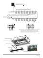
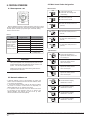
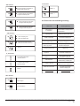
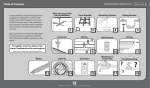
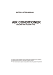
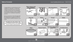
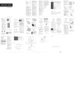
INSTALLATION
MANUAL
Two-way Cassette Type
Digital Scroll and DC/AC Inverter Commercial Air-conditioner
The Digital Scroll and DC/AC Inverter share the same indoor units.
Thank you very much for purchasing our air conditioner,
please read this manual carefully and keep it for future reference.
CONTENTS
PAGE
1. PRECAUTIONS....................................................................................1
2. INSTALLATION INFORMATION........................................................... 2
3. ATTACHED FITTINGS..........................................................................3
4.INSTALLATION....................................................................................4
5. LAYOUT THE DRAIN PIPE...................................................................7
6. INSTALL THE CONNECTING PIPE.......................................................8
7. WIRING.............................................................................................10
8. CONTROL OPERATION......................................................................12
9. TEST OPERATION..............................................................................14
Improper installation, repair, and maintenance may result in
electric shocks, short-circuit, leaks, fire or other damage to
the equipment.
Install according to this installation instructions strictly.
If installation is defective, it will cause water leakage,
electrical shock fire.
When installing the unit in a small room, take measures
against to keep refrigerant concentration from exceeding
allowable safety limits in the event of refrigerant leakage.
Contact the place of purchase for more information.
Excessive refrigerant in a closed ambient can lead to oxygen
deficiency.
Use the attached accessories parts and specified parts
for installation.
otherwise, it will cause the set to fall, water leakage,
electrical shock fire.
Install at a strong and firm location which is able to
withstand the set' s weight.
If the strength is not enough or installation is not properly
done, the set will drop to cause injury.
The indoor unit must be installed 2.5m above floor.
1.
PRECAUTIONS
The appliance shall not be installed in the laundry.
Before obtaining access to terminals, all supply circuits
must be disconnected.
Be sure to be in conformity with the local, national and
international laws and regulations.
The appliance must be positioned so that the plug is
accessible.
Read "PRECAUTIONS" carefully before installation.
The enclosure of the appliance shall be marked by word,
or by symbols, with the direction of the fluid flow.
The following precautions include important safty items.
Observe them and never forget.
Keep this manual with the owner's manual in a handy place
for future reference.
The safty precautions listed here are divided into two categories. In
either case, important safty information is listed which must be read
carefully.
WARNING
Failure to observe a warning may result in death. The
appliance shall be installed in accordance with national
wiring reulations.
CAUTION
Failure to observe a caution may result in injury or damage
to the equipment.
After completing the installation, make sure that the unit operates
properly during the start-up operation. Please instruct the customer
on how to operate the unit and keep it maintained.Also, inform
customers that they should store this installation manual along with
the owner's manual for future reference.
WARNING
Be sure only trained and qualified service personnel to
install, repair or service the equipment.
For electrical work, follow the local national wiring
standard, regulation and this installation instructions. An
independent circuit and single outlet must be used.
If electrical circuit capacity is not enough or defect in
electrical work, it will cause electrical shock fire.
Use the specified cable and connect tightly and clamp
the cable so that no external force will be acted on the
terminal.
If connection or fixing is not perfect, it will cause heat-up or
fire at the connection.
Wiring routing must be properly arranged so that control
board cover is fixed properly.
If control board cover is not fixed perfectly, it will cause
heat-up at connection point of terminal, fire or electrical
shock.
If the supply cord is damaged, it must be replaced by the
manufacture or its sevice agent or similarly qualifued
person in order to avoid a hazard.
An all-pole disconnection switch having a cintract
separation of at least 3mm in a poles should be
connected in fixed wiring.
When carrying out piping connection, take care not to let
air substances go into refrigeration cycle.
Otherwise, it will cause lower capacity, abnormal high
pressure in the refrigeration cycle, explosion and injury.
Do not modify the length of the power supply cord or use
of extension cord, and do not share the single outlet with
other electrical appliances.
Otherwise, it will cause fire or electrical shock.
installation manual
1
There is strong electromagnetic wave existing.
Carry out the specified installation work after taking
into account strong winds, typhoons or earthquakes.
Improper installation work may result in the equipment
falling and causing accidents.
There are inflammable materials or gas.
There is acid or alkaline liquid evaporating.
Other special conditions.
If the refrigerant leaks during installation, ventilate the
area immediately.
Toxic gas may be produced if the refrigerant comes into the
place contacting with fire.
After completing the installation work, check that the
refrigerant does not leak.
Toxic gas may be produced if the refrigerant leaks into the
room and comes into contact with a source of fire, such as
a fan heater, stove or cooker.
The temperature of refrigerant circuit will be high, please
keep the interconncetion cable away from the copper tube.
2.
INSTALLATION INFORMATION
To install properly, please read this "installation manual" at
first.
The air conditioner must be installed by qualified persons.
When installing the indoor unit or its tubing, please follow
this manual as strictly as possible.
CAUTION
Ground the air conditioner.
Do not connect the ground wire to gas or water pipes,
lightning rod or a telephone ground wire.Incomplete
grounding may result in electric shocks.
Be sure to install an earth leakage breaker.
Failure to install an earth leakage breaker may result in
electric shocks.
Connect the outdoor unit wires , then connect the indoor
unit wires.
You are not allow to connect the air conditioner with the
power source until wiring and piping the air conditioner is
done.
If the air conditioner is installed on a metal part of the
building, it must be electrically insulated according to the
relevant standards to electrical appliances.
When all the installation work is finished, please turn on the
power only after a thorough check.
Regret for no further announcement if there is any change
of this manual caused by product improvement.
INSTALLATION ORDER
Select the location;
Install the indoor unit;
Install the outdoor unit;
While following the instructions in this installation
manual, install drain piping in order to ensure proper
drainage and insulate piping in order to prevent
condensation.
Improper drain piping may result in water leakage and
property damage.
Install the indoor and outdoor units, power supply wiring
and connecting wires at least 1 meter away from
televisions or radios in order to prevent image
interference or noise.
Depending on the radio waves, a distance of 1 meter may not
be sufficient enough to eliminate the noise.
The appliance is not intended for use by young children
or infirm persons without supervision.
Young children should be supervised to ensure that they
do not play with the appliance.
Don't install the air conditioner in the following locations:
There is petrolatum existing.
There is salty air surrounding (near the coast).
There is caustic gas (the sulfide, for example) existing in
the air (near a hot spring).
The Volt vibrates violently (in the factories).
In buses or cabinets.
In kitchen where it is full of oil gas.
installation manual
2
Install the connecting pipe ;
Connect the drain pipe;
Wiring;
Test operation.
3.
ATTACHED FITTINGS
Please check whether the following fittings are of full scope. If there are some spare fittings , please restore them carefully.
Accessory name
Qty.
Installation & Owner’s Manual
1
Heat-insulated Pipe
2
Use for heat-insulating of pipe connecting parts
Protection Pipe
1
Use for heat insulation of flexible pipe
Matched Resistance(also
Network Matching Wiring Group)
1
Improve the stability of communication
Bolt
4
Fix the installation template paper
Nut
8
Washer
8
Hanging component
Flexible Pipe
1
Drain piping
Remote Controller
Installation Instruction
1
Remote controller instruction
Remote Controller
Components
1
Remote control the air-conditioner
Installation Template Paper
1
Assist the indoor unit installation(in the
installation of the panel)
Drain Pipe Clasp
1
For drain pipe installation
Lacing Belt
5
Shape
This Book
Usage
Indoor Unit Installtion Instruction(Please Do
Hand to User)
Hanging component
Attached Foam I
250×250×10
1
Heat insulation
Attached Foam II
60×100×5
1
Heat insulation
Battery
2
Power supply for remote controller
Cautions on remote controller installation:
Never throw or beat the controller.
Before installation, operate the remote controller to determine its location in a
reception range.
C
Keep the remote controller at least 1m apart from the nearest TV set or stereo
equipment. (it is necessary to prevent image disturbances or noise interferences.)
Do not install the remote controller in a place exposed to direct sunlight or close to a
heating source, such as a stove.
Note that the positive and negative poles are right positions when loading batteries.
This manual is subject to changes due to technological improvement without further
notices.
Remote
controller
Fig.3-1
installation manual
3
4. INSTALLATION
CAUTION
4.1 Installation place
The indoor unit should be installed in a location that meets
the following reauirements:
There is enough room for installation and maintenance.
The ceiling is horizontal, and its structure can endure the
weight of the indoor unit.
The outlet and the inlet are not impeded, and the
influence of external air is the least.
The air flow can reach throughout the room.
Installing the equipment in any of the following places may lead to
faults of the equipment (if that is inevitable, consult the supplier):
A. The site contains mineral oils such as cutting lubricant.
B. Seaside where the air contains much salt.
C. Hotpring area where corrosive gases exist, e.g., sulfide gas.
D. Factories where the supply voltage fluctuates seriously.
E. Inside a car or cabin.
F. Place like kitchen where oil permeates.
G. Place where strong electromagnetic waves exist.
H. Place where flammable gases or materials exist.
I. Place where acid or alkali gases evaporate.
J. Other special environments.
The connecting pipe and drainpipe could be extracted out
easily.
There is no direct radiation from heaters.
≥350
This air-conditioner shold install on the 3m high ceiling.
≥100
≥1000
≥100
>2500mm
≥1500
Ceiling
≥1500
Fig.4-1
Floor
4.2 Preperaration of installation
4-2-1 The position relation graph of the ceiling opening and the hanging screw.
Water pump outlet
Electronic expansion
valve inspection hole
Water inlet hole and the water
level switch inspection hole
Lifting lug
Liquid side connecting pipe
Indoor unit
Fresh air connector
Both sides reserved air outlet
Lifting lug
Panel
Air side connecting pipe
Maintenance water outlet
Fig.4-2
installation manual
4
591
436
Unit:mm
1172
701
51
44
91
20
1430
The panel contour dimension 1430
The ceiling opening dimension 1390
Hanging screw bolts distance 1207
Machine body size 1172
680
The ceiling opening
dimension 640
Machine body
size 591
Hanging screw
bolts distance 520
20
701
129
44
151
20
The panel contour
dimension 680
20
The ceiling opening (1390*640)
42~45
Φ32
Φ
12
241
185
120 104
299
176
171
91
151
45
5
Φ160
192
299
117
Φ32
Fresh air connector 257
129 129
44
57
Fig.4-3
4-2-2 Open the ceiling on the proper place.
■ The relative position relation of the ceiling and air-conditioner
1) The ceiling opening: The opening dimension please refers to the
panel attached installation template paper; for different
building structure, the actual situation please consults with the
architecture interior decoration personnel.
150mm
2) Disposal of the ceiling: To make sure the horizontal of the ceiling
and avoid the ceiling vibration, the base frame of the ceiling
must be strengthened.
3) Cut off and remove the base frame of the ceiling.
4) Strengthen the end face which left after take off the ceiling, and
strengthen the base frame use for fixing the both sides of
the ceiling.
5) After installing the main body, then piping and wiring in the
ceiling, and then decide the piping leading out direction after
selecting the installation location.
Especially in the situation where already has ceiling, please wiring
the refrigerating pipe, drain pipe, indoor and outdoor units
connecting wire and line-controlling wire to the connecting
positions.
6) Please use M10 hanging bolt.
Surface of the opening ceiling
Fig.4-4
NOTE
All the pictures in this manual are for explanation purpose only.
They may be slightly different from the air conditioner you
purchased(depend on model).The actual shape shall prevail.
installation manual
5
●
4.3 Indoor unit installation
Overhanging the indoor unit
●
Fix the pattern paper to the down side of indoor unit with panel
fixing screw. Adjust the size of ceiling hole according to pattern
paper.
Pattern paper
Adjust the gasket (down side) to 150mm over the ceiling .
Down side of pattern paper
Hanging Bolt
Down side of ceiling
Nut (Up Side)
Fig.4-9
Gasket (Up Side)
●
Installing Ear
Down side of ceiling must be level with down side of the pattern
paper.
138mm
Gasket (Down Side)
Nut (Down Side)
Indoor unit
Down Side of the ceiling
Down side of
pattern paper
at the same level
Fig.4-5
●
Down side of ceiling
Fig.4-10
Fasten the upside nut
Level gauge
4.4 Procedure of installing the pendant bolt
Base on the unit structure, please set the screw-pitch according to
the size of the following figures:
Table: 4-1
Secure it safety
Fig.4-6
Woodenstructure
Wooden
structure
Put rectangular sticks across the beams, and set pendant bolts.
Install the hanging bolt into U groove of the hanging tool.
Overhang the indoor unit and ensure it is level using a level
gauge.
Adjust the relative position between indoor unit and ceiling
hole with the pattern paper again.
Wooden span
Beam
Ceiling
Pendant bolt
Pattern paper
Old concrete roughcast
Use embedded bolts and embedded pulling plugs.
Ceiling hole
width 640
24
Panel fixing screw (M4X16)
91
Hole
Outline of indoor Unit
1390
Ceiling hole length
installation manual
6
Fig.4-7
91
Fig.4-8
Table: 4-2
3) Water-pumping pipe and drainpipe from main body must be
wrapped by insulation tube evenly, and bound by tighten band for
obstructing air getting in and coagulation.
Steel beam and girder structure
Set and use supportive angle steel.
Suspended bolt
Pendant bolt
Supportive angle steel
Set it with embedded bushes or embedded bolts.
Concrete iron
Embedded bolt
(With embedded
bolt in pipe)
Slide type inser
5) When connecting drainpipe, don’t drag the pipe that would pull
the main unit. For this, please arrange bearing points every 0.8 to
1.0 meter to avoid pipe be bended (See Fig.5-1 b).
6) When connect a lengthen drainpipe, apply protective tube to
wrap its indoor parts for ensuring the lengthen part connected
tightly.
New concrete roughcast
Flap type inser
4) Prevent from water backflow into unit inside during shutdown,
the drain pipe shall place down side and drain water to outdoor
(drain side), the gradient of the drain pipe should be higher than
(1/100), without salient and water remain.(Refer to Fig.5-1 a)
7) In case the drainpipe outlet is higher than pumping connective
pipe of the main body, the drainpipe must be arranged upwards
vertically by using connective assembly of the water outlet for
vertical bending, and the height of the drainpipe shall set to the
defrosting pan surface no more than 1000mm, otherwise, too much
backflow while shutdown would leads to overflow (Refer to
Fig.5-2).
8) Base on the actual requirement to bend piping, and use
connective assembly of water outlet in terminal box for pipe layout.
5. LAYOUT THE DRAIN PIPE
CAUTION
5.1 Install the drain pipe of indoor unit
The joints in drain system must be sealed to avoid water leakage.
1) The drainpipe can use PVC pipe (external diameter about 37~
39mm, inner diameter is 32mm).
9) The height from floor to the end of drainpipe or the bottom of
drain slot must more than 50 mm. Don’t immerse the end of
drainpipe or the bottom of drain slot into water. When drain
condensate liquid to raceway, please bend the drainpipe to a
U-sharped hydroseal for avoiding stench transmitted by drainpipe
to indoor.
2) Joint drainpipe connector to the end side of water pumping pipe,
and fix drainpipe together with water outflow pipe and thermal
insulation tube by clasp of water outflow pipe (attached).
CAUTION
Don’t use forcing strength to crack the water-pumping pipe.
0.8~1.0 m
Gradient:
higher than 1/100
>1.0 m
a
b
Fig.5-1
50~100mm
≤200mm
≤200mm
50~100mm
Connective assembly of water outlet
Main drainpipe
50~100mm
Max. 1000mm
≤200mm
Gradient: 1/50~1/100
Drainpipes from many units confluent water to main drainpipe and discharge to cloacae.
Fig. 5-2
installation manual
7
5.2 Confirm dewatering
Table: 6-1
1) Remove the water testing cover and through the water testing
orifice, use the refilling pipe to fill 2000ml water into the water
Indoor unit model
Piping size (mm)
Liquid side
Air side
pond (refers to Fig.5-3).
2200W~4500W
Φ6.4
Φ12.7
2) Power on, and operate the cooling of the air-conditioner. Check
5600W~7100W
Φ9.5
Φ15.9
the running sounds of the dewatering pump, and check the drain
outlet whether can drain normally (depends on the time of
draining, it will be delayed 1 minute then can drain), and check all
the connectors whether leak or not.
3) Stop running the air-conditioner, and check whether has any
abnormal situation after 3 minutes. If the drain pipe be laid out
unreasonable, the water will backflow too much and cause the
alarm lamp of the control box be flashed, or even overflow from
the water pond.
4) Continue to fill water until the water level over alarm water level
6.3 Procedure of connecting pipes
1. Measure the required length of the connective pipe, and make the
connective pipes in the following procedure. (Refer to Pipeline
Connection for details)
1) Connect the indoor unit first, and then connect the outdoor unit.
a. The pipe bend should be handled carefully, without damaging the
pipe and insulation layer.
b. Before screwing up the flared nut, apply refrigerant oil at the outer
surface of the pipeline flare and the taper surface of the connection
nut. Screw up the nut for 3~4 circles beforehand (see Fig.6-1).
and stay on this state for 3 minutes, the machine will alarm and
shut off, and then it can be operated normally until power off and
Apply refrigerant oil
remove the water.
5) Power off, and remove the water, then install the water testing
cover back to the formal place.
Water inlet hole and the water
level switch inspection hole
Fig.6-1
Water pump outlet
c. When connecting or disconnecting the pipeline, be sure to use
two spanners concurrently.
d. Do not rest the weight of the connective pipe on the adapter of the
indoor unit. Too heavy load on the adapter of the indoor unit may
deform the pipe and thus affect the cooling/heating effect.
Water refill pipe
Maintenance drain plug
Fig.5-3
WARNING
The drain plug on the side of the main unit is using for dewatering
the water pond when the air conditioner came out fault and
maintaining, while using the unit please stuff this drain plug, for
avoiding leakage. The specified position of the drain plug please
refers to Fig.5-3.
6. INSTALL THE CONNECING PIPE
6.1 The connective length of indoor and outdoor
piping and those height difference requirements.
Connect to different outdoor units with different connective length
and height difference requirements. Please refer to Indoor Unit
Installation Manual for detail.
2) The valve of the outdoor unit should be closed completely (as in
the factory status). Every time when connecting the pipe, screw off
the nut at the valve, and connect the flared pipe (within 5 minutes). If
the nut is put away for a long time after being screwed off the valve,
dust and other foreign substance may intrude into the pipeline
system and lead to fault.
3) After the refrigerant pipe is connected to the indoor and outdoor
units, expel air as instructed in the “Expel air” section. After expelling
the air, screw up the nut at the maintenance orifice.
a.Precautions for the flexible part of the pipeline
i.The bend angle shall not exceed 90°. (See Fig.6-2)
Use a thumb to bend the pipe
Minimum radius 100mm
Fig.6-2
ii. The bend shall be preferably in the middle of the pipe length, and
higher bend radiuses are preferred.
iii. Do not bend the flexible pipe for over 3 times.
b. Bend the thin-wall connective pipe (See Fig.6-3)
6.2 Piping materials and size
1) Piping materials: Copper tube special for air conditioner, normally
T2M.
Method of unleashing the spooled pipe
Straighten the pipe end
2) Piping size: Please refer to Table: 6-1
Fig.6-3
installation manual
8
i. When bending the pipe, cut out a notch of the desired size at the
bend of the adiabatic pipe, and then expose the pipe (wrap the pipe
with the wrapping tape after bending it).
ii. The radio of the elbow pipe should be as large as possible to
prevent flattening or crush.
iii. Use the pipe bender to make close elbow pipe.
2. Tighten the nut
Align with the connective pipe, screw up the connection pipe nut
manually, and use a spanner to tighten it as shown in Fig.6-5.
c. Use purchased copper pipe
When the cooper pipe is purchased from the market, be sure to use
the heat insulation materials of the same type (with a thickness of
over 9mm).
2. Deploy the pipelines
Fig.6-5
1) Drill a porthole on the wall, and put the hole sheath and hole
cover through the wall.
2) Place the connective pipe together with the indoor & outdoor
connection wires. Use wrapping tape to tie them tight. Do not let
air penetrate into it lest condensation and drips of moist.
3) Pull the connective wrapped connective pipe from outdoor
through the sheath, which gets through the wall, and lead it into
the room.
CAUTION
According to the installation conditions, too large torque will
damage the flaring, and too small torque will lead to looseness
and leakage. Determine the tightening torque by reference to
Table: 6-3.
Table: 6-3
3. Make a vacuum of connective pipeline.
4. After the above steps are completed, the spool of the valve of
the outdoor unit should be completely open, and the refrigerant
pipeline of the indoor unit and the outdoor unit should be smooth.
5. Use a leak detector or soap water detect leak carefully to
prevent leakage.
6. Put on an adiabatic envelope (accessory) at connective pipe
adapter of the indoor unit, and wrap it tight with the wrapping tape
lest condensate and leakage.
6.4 Pipeline connection
Pipe Size
Torgue N.m
Φ6.4
14.2~17.2 N.m
(144~176 kgf.cm)
Φ9.5
32.7~39.9 N.m
(333~407 kgf.cm)
Φ12.7
49.5~60.3 N.m
(504~616 kgf.cm)
Φ15.9
61.8~75.4 N.m
(630~770 kgf.cm)
Φ19.1
97.2~118.6 N.m
(990~1210 kgf.cm)
1. Flare
1) Use a pipe cutter to cut off the pipe (See Fig.6-4)
CAUTION
Slant
90
Coarse
Burr
Please beware when install connective pipe, do not let any air,
dust or other foreign substance invading into system.
Pipes connection could be conducted after the indoor and
outdoor unit are be fixed.
Connective pipe must keep in dry when installation, do not let
water invade in it.
Connective copper pipe must be wrapped insulation layer (at
least 9 mm thickness)
Fig.6-4
2) Pull the pipe into the rear flare of the connective nut. (Refer to
Table: 6-2)
Apply vacuum pump expels air from refrigerant charging vent of
air side in outdoor unit.
It is forbidden to apply the refrigerant inside of indoor unit for
vacuum air.
Table: 6-2
Outer
diameter
(mm)
Max.
Min.
Φ6.4
8.7
8.3
Φ9.5
12.4
12.0
Φ12.7
15.8
15.4
Φ15.9
19.0
18.6
Φ19.1
23.3
22.9
6.5 Air expels
A(mm)
90 °± 4
45 °
±2
A
R0.4~0.8
6.6 Open valve
Employ a 5 mm hexagon spanner to open the valve spool of
indoor and outdoor unit.
6.7 Leak detection
Use soap water to check whether gas leakage exists at the
adapters
installation manual
9
7.2 Power specification
6.8 Thermal insulation
The power cable specifications are as follows. In case power
capacity is too low may result in over-heating of piping that
would be burned out the unit (refers to Table 7-1).
To process the thermal insulation for air side and liquid side
piping. Please insulted the air side and liquid side piping
completely, in the reason of during operate cooling mode the
ambient temperature is very low.
1) Thermal insulation at least 120 °C material shall be apply for air
side piping.
2) Apply attached thermal insulation material to wrap the
connective part of indoor piping tightly without gap.
7.3 Indoor and outdoor unit communication wire
1) The controlling wire has to use shielding line. Use other wires
may produce signal disturb and cause malfunction.
2) Inter-connect all the shielding nets of shielding line, and at last
be together connect to the metal plate grounding “
Cut it from up to down
”(refers to
Fig.7-1).
3) Prohibit tying up controlling wire and refrigerant pipe, power
Unit body
line etc. together. When the power line and the controlling wire
Field piping side
are parallel lain, their distance should be at least 300mm, for
Subsidiary belt of thermal
insulation pump
avoiding the signal source will be disturbed.
Fig.6-6
7.
4) The controlling wire can not be closed loop.
WIRING
5) The controlling wire has polarity, and pay attention while wiring
and wire correctly.
7.1 Electrical wiring
6) The indoor and outdoor units please use three-core shielding
wire (greater than or equal to 0.75mm²), and the shielding wire
CAUTION
has polarity, and need to be wired correctly; The indoor and
1) Special power shall be applied within rated voltage range.
External circuit of this air conditioner must be grounded that
means power cable of outdoor unit shall be jointed with external
grounding wire reliable.
outdoor unit signal wires can only be led out and connect from
the outdoor main unit.
7.4 Indoor unit power supply
2) Electric wiring must be done by professionals, and wiring
according to the wiring label.
1) The indoor unit power source should not be shared with
3) Fixing circuit must be wired with an a11-poledisconnection
device at least 3mm switching distance of contact.
outdoor unit.
4) Setting the electrical leakage device according to national
regulation.
use the same power source, creepage protector and main
2) The indoor units that connect to the same outdoor unit should
switch.
5) Power cables and signal wires shall be arranged orderly and
be wired rational without mutual interfere, and connective pipes
and body of valves without mutual contact among them.
6) The attached connective wire is 10m, provided that the
length were not long enough, you must replace it by an
appropriate length connective wire in the same specification. In
a normal circumstance, it is not allowed to overlapping the two
wires, but welded fix and wrapped by insulation adhesive band
is except.
7) All electric wiring is finished, you could input power as long
as confirm that all wires connect are correct and fix tightly.
7.5 Dispose of the wiring connector
Use attached heat-insulating materials to seal up the wiring
connector, and if sealing failure it will cause condensation.
7.6 The wiring of the panel
Connect the swinging motor wire holder according to the Panel
Installation Instruction.
7.7 Terminal board setup diagram
Wiring refers to the every indoor unit connecting diagram.
Table 7-1
Power supply of indoor part
Connect wiring
Item
Power switch
Model:MDV-D
2200W~7100W(N1)
2200W~7100W(DN1)
installation manual
10
Power supply
Capacity
Safety
fuse
Signal-phase
220-240V~,
1PH,50Hz
15A
15A
Power cable
Signal wire of indoor
and outdoor unit
Below 20m Below 50m Qty.
Wire diameter
2×2.5mm2
2×6mm2
2×4mm2
2×6mm2
Three-core
shielding wire
0.75mm2
1
Ground Line
Single-line
2.5mm2
Single-line
3.0mm2
Outdoor Unit
(All the shielding terminals of the
shielding wires connect to the metal plate
of the electric control box “
”)
(P Q E)
Signal wires between indoor and outdoor units
Connect all shielding layer of the shielding wires
The last set unit needs to add matched resistance in the P, Q terminals
(The indoor unit accessory contains matched resistance).
P
Matched
Resistance
(Open)
Q
Control with groups
(P Q E)
Signal wires of indoor
and outdoor units
Fig.7-1
白
L
N
To indoor power
220-240V~ 50Hz
蓝 黑
X Y (E)
黄
灰 黑
P Q (E)
Communication wire to centralized controller Communication wire to outdoor unit
Communication wire to centralized controller and outdoor unit please
refer to Fig.7-1 the communication wiring method of indoor and outdoor
units systems, the shielding layer only ground at one place.
Fig.7-2
Power-supply wiring holder
Communication wiring holder
Electric control box cover
Power-supply wiring holder
Inhalation grating
Communication wiring holder
Fig.7-3
installation manual
11
8.3 Main board Code designation
8. CONTROL OPERATION
8.1 Hoursepower set
SW1 definition
ON
ON
9
78 A
BC
3 4 56
DE
F 012
ENC1
ON
Base on different purposes to setting the switch cords on PC panel
of indoor electrical control box. Once finish the setting, please cut off
the main power, and then input power again, otherwise, setting
function could not work.
Table.8-1
Note: The horsepower
has been set before
leaving the factory ,
anyone can’t
modify it except the
maintenance person.
1234
SW1
1234
SW1
● 1 means factory test mode
● 0 means add. auto searching mode
(default setting)
● 1 means factory test mode
● 0 means AC fan Is chosen
● 00 means DC fan static pressure is 0
(reserved)
1234
ON
ENC1
SW1
SW1
● 01 means DC fan static pressure is 1
(reserved)
1234
Toggle switch
For set horsepower
Code
Capacity(Horsepower)
0
2200W(0.8HP)
1
2800W(1.0HP)
2
3600W(1.2HP)
3
4500W(1.5HP)
4
5600W(2.0HP)
5
7100W(2.5HP)
ON
The system together have 64units(0-63),everyone has only
system addresscode,If two addresses are the same in one
system , the abnormal operation will occur.
● 10 means DC fan static pressure is 2
1234
ON
SW1
1234
(reserved)
● 11 means DC fan static pressure is 3
(reserved)
SW2 definition
ON
CAUTION
SW1
ON
ON
Please switch off the power before setting,otherwise the
unexpected error will occur.
ON
SW2
1234
SW2
1234
SW2
1234
SW2
1234
● 00 means the temperature is 15
degrees when shutting down the unit
for cold wind proof.
● 01 means the temperature is 20
degrees when shutting down the
unit for cold wind proof.
● 10 means the temperature is 24
degrees when shutting down the
unit for cold wind proof.
● 11 means the temperature is 26
degrees when shutting down the
unit for cold wind proof.
8.2 Network address set
●
Network address is set by communication of indoor and
outdoor unit; the address is the same as indoor address, there
is no need to set separately.
● The central control of indoor units can be done on outdoor
unit, there is no need to control indoor unit separately, for
details please refer to V4+ outdoor unit manual.
● For previous control of indoor units, the network can be set
by connecting (X,Y,E) terminals, there is no need to set
network address. The network can also be set by outer
network module and main board (CN20).
ON
SW2
● 00 means the time of stopping
1234
ON
SW2
TERMAL fan is 8 minutes
ON
SW2
● 10 means the time of stopping
TERMAL fan is 12 minutes
1234
SW2
1234
12
● 01 means the time of stopping
1234
ON
installation manual
TERMAL fan is 4 minutes
● 11 means the time of stopping
TERMAL fan is 16 minutes
0/1 definition
SW5 definition
ON
SW 5
● 00 means temperature compensation is
ON
6 degrees under heating mode
Means 0
1 2
ON
SW 5
● 01 means temperature compensation is
1 2
ON
S W5
2 degrees under heating mode
● 10 means temperature compensation
ON
Means 1
8.4 Fault code and indicating meaning
is 4 degrees under heating mode
1 2
ON
S W5
● 11 means temperature compensation
SW6 definition
ON
SW6
1 2 3
SW6
1 2 3
SW6
ON
Indicating Meaning
First power on,
if no address
The timing and operating lamps
will be flashed or display FE at
the same time
M_Home not
matching fault
4 Lamps will be flashed or
display H0 at the same time
Mode conflict fault
The defrosting lamp will
be flashed or display E0
Indoor and outdoor units
communication fault
The timing lamp will be
flashed or display E1
is 8 degrees under heating mode
1 2
ON
Fault Code
● 1 means old display panel
● 0 means new display panel
● 1 means auto wind under auto mode
● 0 means auto wind under non auto mode
reserved
Indoor unit temperature
sensor (T1) fault
The operating lamp will be
flashed or display E2
Swinging motor fault
Display E8
Temperature sensor
(T2) fault
The operating lamp will
be flashed or display E3
Temperature sensor
(T2B) fault
The operating lamp will
be flashed or display E4
EEPROM fault
The defrosting lamp will be
flashed slowly or display E7
Outdoor unit fault
The alarm lamp will be
flashed slowly or display Ed
Water level alarm fault
The alarm lamp will be
flashed or display EE
1 2 3
J1,J2 definition
J1
J1 no Jumpers means power
off memory function
J1
J1 Jumpers means no power
off memory function
J2
reserved
SW7 definition
ON
SW7
Standard configure
1 2
ON
SW7
Last one in the network
1 2
installation manual
13
9. TEST OPERATION
●
The indoor unit
●
Whether the switch on the remote controller works well.
●
Whether the buttons on the remote controller works well.
Please confirm the following points before the test operation:
●
Whether the air flow louver moves normally.
●
The indoor unit and outdoor unit are installed properly.
●
Whether the room temperature is adjusted well.
●
Tubing and wiring are correctly completed.
●
Whether the indicator lights normally.
●
The refrigerant pipe system is leakage-checked.
●
Whether the temporary buttons works well.
●
The drainage is unimpeded.
●
Whether the drainage is normal.
●
The heating insulation works well.
●
Whether there is vibration or abnormal noise during operation.
●
The ground wiring is connected correctly.
●
●
The length of the tubing and the added stow capacity of the
refrigerant have been recorded.
Whether the air conditioner heats well in the case of the
HEATING/COOLING type.
●
The outdoor unit
●
The power voltage fits the rated voltage of the air conditioner.
●
Whether there is vibration or abnormal noise during operation.
●
There is no obstacle at the outlet and inlet of the outdoor and
indoor and indoor units.
●
Whether the generated wind, noise, or condensed water by the
air conditioner have influenced your neighborhood.
●
The gas-side and liquid-side stop values are both opened.
●
Whether any of the refrigerant is leaked.
●
The air conditioner is pre-heated by turning on the power.
The test operation must be carried out after the entire installation
has been completed.
According to the user’s requirement, install the remote controller
frame where the remote controller’s signal can reach the indoor
unit smoothly.
Test operation
Set the air conditioner under the mode of “COOLING”with the
remote controller, and check the following points per the “Owner’s
Manual”If there is any malfunction, please resolve it through
chapter “Troubles And Causes ”in the “Owner’sManual”.
installation manual
14
A protection feature prevents the air conditioner from being
activated for approximately 3 minutes when it is restarted immediately after shut off .