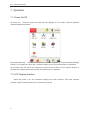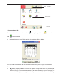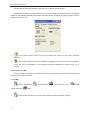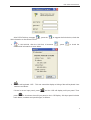
1
DSL-3020V xDSL Tester User Manual V1.1 Profile Thank you for selecting our DSL-3020V Tester to manage and troubleshoot xDSL circuits. This user manual contains information about product functions, installation, connection and operations, and troubleshooting. To ensure easy operation, please read this user manual carefully and keep it with your DSL-3020V for quick reference. Notes˖ ¾ ¾ ¾ Please note that future updates of features and functions may not be included in this user manual. To improve this user manual, please contact us via the contact information on the cover page if you find any errors. All Rights Reserved. No part of this publication can be reproduced, stored in any retrieval system of any nature, or transmitted, in any form or by any means, electronic, mechanical, photocopying, recording, etc., without prior permission of DADI TELECOM. User Manual The User Manual contains 8 chapters and 1 appendix. Chapter 1 Items Remarks Overview Introduction of the instrument Unpacking and Inspection Introduction of the parts included in the Package Safety Description of how to use the product safely 4 General operation and user notes Introduction of the operation and user notes 5 System chart and instrument configuration Introduction of the system chart and instrument configuration 6 Main Functions and Technical Parameters Introduction of the main functions and technical parameters Operation Description on how to operate the DSL-3020V Malfunction Analysis and Solution Introduction of general malfunctions, reason and solutions. Basic questions and solutions for xDSL Introduction of some basic questions and solutions for xDSL 2 3 7 8 Appendix 1 DSL-3020V User Manual TABLE OF CONTENTS 1. OVERVIEW...................................................................................................................... 4 2. UNPACKING AND INSPECTION ................................................................................. 4 3.SAFETY............................................................................................................................. 5 4. GENERAL OPERATION AND USER NOTES............................................................ 6 4.1 GENERAL OPERATION .....................................................................................6 4.2 USER NOTES ..................................................................................................6 5. INSTRUMENT CONFIGURATION ............................................................................... 7 5.1 INSTRUMENT CONFIGURATION .........................................................................7 5.1.1 Instrument Front View ...................................................................................... 7 5.2.2 Instrument Interface.......................................................................................... 8 5.2.3 Other Parts......................................................................................................... 8 6. MAIN FUNCTIONS AND TECHNICAL PARAMETERS ................................................9 6.1 XDSL TEST ....................................................................................................9 6.2 LAN TEST ....................................................................................................10 6.3 COPPER TEST ..............................................................................................10 6.4 MODEM EMULATION ....................................................................................10 6.5 DOCUMENT MANAGEMENT ............................................................................11 6.6 HELP ...........................................................................................................11 6.7 OTHER .........................................................................................................11 7. OPERATION.................................................................................................................. 12 7.1 POWER ON/OFF ...........................................................................................12 7.2 LCD DISPLAY INTERFACE ..............................................................................12 7.3 XDSL TEST ..................................................................................................16 7.3.1 Physical Layer Parameters............................................................................ 17 7.3.2 DSL Parameters Settings .............................................................................. 23 7.3.3 MODEM EMULATION ...................................................................................25 7.3.4 IPOE OPTIONS ..........................................................................................26 7.3.5 PPPoE Dial-up................................................................................................. 28 7.3.6 Network Layer Test ......................................................................................... 29 7.3.6.1 Ping Test ....................................................................................................... 29 7.3.6.2 Ipconfig Test.................................................................................................. 30 7.3.6.3 Route Test..................................................................................................... 31 7.3.6.4 Traceroute Test............................................................................................. 33 7.3.7 Web Browse..................................................................................................... 34 7.3.8 HTTP download speed Test........................................................................... 35 7.3.9 FTP Speed Test............................................................................................... 36 7.4 LAN TEST ....................................................................................................37 7.4.1 Network Card Properties................................................................................ 38 2 DSL-3020V User Manual 7.4.2 PPPoE Property .............................................................................................. 39 7.4.3 Dial-up............................................................................................................... 41 7.4.4 Network Layer Test ......................................................................................... 41 7.4.5 Web Browse..................................................................................................... 42 7.4.6 Web Speed Test .............................................................................................. 42 7.4.7 FTP Speed Test............................................................................................... 42 7.5 COPPER TEST ..............................................................................................42 7.5.1 DMM Test ......................................................................................................... 43 7.5.2 Tone Generator................................................................................................ 46 7.6 DOCUMENT MANAGEMENT ............................................................................47 7.6.1 View Record..................................................................................................... 48 7.6.2 U Discs Storage............................................................................................... 51 7.7 HELP ...........................................................................................................52 7.7.1 System Upgrade.............................................................................................. 53 7.7.2 User Notes ....................................................................................................... 54 7.7.3 About Version .................................................................................................. 54 7.8 Settings ................................................................................................................ 54 7.8.1 System Parameter Setup............................................................................... 55 7.8.2 Touch Screen Calibration............................................................................... 56 7.9 CHARGE THE INSTRUMENT ............................................................................58 7.10 REPLACE BATTERY .....................................................................................58 8. MALFUNCTION ANALYSIS AND SOLUTION.......................................................... 59 APPENDIX XDSL BASIC PROBLEMS AND SOLUTIONS......................................... 60 3 1. Overview The DSL-3020V is designed to simplify installing and troubleshooting xDSL lines (includes ADSL1/ADSL2/ADSL2+,VDSL2,etc.). The unit can test various parameters of the xDSL physical layer, help you confirm whether the xDSL service is ready to go live for user circuits, and evaluate overall service quality. It supports PPPoE dial-up and can emulate a xDSL modem to verify connectivity from the user to the ISP service. After dial up, the tester can perform network layer tests such as Ping, Ipconfig, Route, Tracert Test and Web Browser The DSL-3020V can emulate user PC’s, test Broadband IP circuits, verify connectivity of Broadband IP, help resolve user modem malfunctions and clarify if there is failure to browse websites because of a PC problem. The DSL-3020V uses a 480×272 color TFT LCD touch screen, embedded Windows CE operating system, and has a user-friendly interface. It is easy to operate and view test results and is a the ideal tool for technicians responsible for installing, maintaining and troubleshooting xDSL circuits. 2. Unpacking and Inspection Upon receiving the package, conduct a visual inspection of the box to see if it has suffered any damage. If not, proceed with unpacking and make sure that all items in the packing list are included. Excessive shock and vibration should be avoided during shipping and unpacking. Please also check any extra accessories you purchased against the packing list. Contact DADI TELECOM if anything is missing or damaged. Main Parts: Please inspect that the type and code on the instrument matches the following: Type DSL-3020V Code Language -CN Chinese -EN English Standard Accessories: The following accessories should be included; please inspect that nothing has suffered any damage. Item Specs Stylus 4 Quantity 1 RJ11 TO Alligator Clip Cable 2.0m 1 Cross over Cat5 Ethernet Cable 1.5m 1 Power Supply 8.4V/2.0A 1 DSL-3020V User Manual User Manual 1 Carrying Case/W Strap 1 Optional Accessories: The following options can be purchased. Item Specs Tone Generator TPT-8010A Mouse USB port U Disk 4G Quantity 3.Safety Safety precautions should be observed at all times. DADI TELECOM does not undertake any responsibility if the instrument is damaged due to wrongful operation by customer. Please comply with Safety precautions to avoid personal injury or instrument damage.. Warning ¾ Charge Battery To charge battery, please use the charger provided by the Factory. An unauthorized charger may damage the instrument ¾ Replace Battery Please use the Lithium battery configured by Factory. Please comply with clause 7.10. ¾ Do not Operate in Flammable Environment Do not use the instrument near or in Flammable/Explosive liquids, gases or substances. ¾ Do not Open the Back Cover Unless replacing modules, please do not open the Back Cover. Only a trained technician should open the back cover as some parts of the instrument contain high voltage circuits and improper operation could be dangerous. ¾ LCD Display If the LCD Display is damaged or liquid flows out, please do not touch the liquid. If the liquid is splattered into eyes or mouth, please wash with water and go to hospital for medical attention. If the liquid is splattered on skin or clothes, please wash with water or soap after treating with alcohol. Also, note that to avoid skin (finger, hand, etc.) injury by glass fragments, avoid touching any fragment’s edge. 5 DSL-3020V User Manual 4. General Operation and User Notes 4.1 General Operation ¾ Test Interface Please connect test line with the instrument interface first, then connect the instrument with the tested circuit. Please do not touch the bare metal parts of the test nip to prevent electric shock if high voltages are present on the circuit. ¾ USB interface Please do not insert electric equipment into USB interface and do not short-circuit interface with metals, otherwise the inner circuit will be destroyed. ¾ Display Please remove the protective film enclosed for delivery before using the instrument. ¾ Cleaning The instrument cover, mainly made of plastics, should be cleaned by a soft dry cloth. Remember not to use volatile chemicals, otherwise, it may discolor or distort its shape. ¾ Cover and Panel Protection Please do not spray volatile chemicals on cover or panel. ¾ Instrument Movement When moving the instrument, please ensure that the power line and connection cable are first disconnected from instrument. ¾ Battery Maintenance When the instrument will not be used for a long period of time, the battery charge will decrease. The battery should then be charged to full before using the instrument.. ¾ Malfunction If there are abnormal sounds, scents or smoke, please shut down instrument, unplug the power line and contact DADI TELECOM. 4.2 User Notes ¾ ¾ ¾ ¾ Before using the tester for the first time, please fully charge the instrument Please touch LCD screen gently when using touch pen to avoid damage. If an abnormal message is displayed, systems halted, etc, please reboot the instrument. Please do not put instrument in the sun or near a direct heat source, otherwise it may have a negative effect on the instrument and its test results. ¾ Condensation may occur if the instrument is moved to a higher temperature or temperature variable location. Under this circumstance, it is recommended for the instrument to adapt to the temperature for more than one hour before using. 6 DSL-3020V User Manual 5. Instrument Configuration 5.1 Instrument Configuration 5.1.1 Instrument Front View ķIndicator Lights Includes: Power Indicator Light, Ethernet Indicator Light, xDSL LINK Indicator Light, xDSL ACT Indicator Light. Specifications are as follows: ¾ Power Indicator Light: constant red light indicates power up. ¾ Modem power Indicator Light: constant blue light indicates embedded xDSL modem power up. ¾ DSL LINK Indicator Light: slowly blinking green light indicates that it is seeking xDSL signal; fast blinking green light indicates xDSL training; constant green light indicates that xDSL links have been established. ¾ LAN LINK Indicator Light: constant orange light indicates Ethernet links have been established. ¾ LAN ACT Indicator Light: blinking green light indicates that Ethernet has a data stream. ĸ Keystroke Definition for each key are as follows: ¾ Power Key: with the unit in the on state, press the Power Key for 1 second to suspend the instrument. To complete shut off , please press Power key and hold on for 5 seconds. ¾ Soft key On-off: in operation interface, press to switch or close soft keyboard. ¾ Help/ transverse and vertical Screen Switch: To operate WEB Browser, press to switch from 7 DSL-3020V User Manual transverse and vertical Screen along with system help. Ĺ LCD Display The TFT color LCD Display, is touch screen with lattice 480×272. 5.2.2 Instrument Interface ķ Touch Pen The Touch Pen accessory is used to click and operate on the screen. ĸ Ethernet Interface RJ45 interface complies with Ethernet interface standard, and is used to connect with Ethernet cable or RJ45 cable plug for Broadband IP. The interface supports auto crossover detection function. Ĺ xDSL Interface This is the xDSL user line interface; it is also the input interface for the digital multi-meter (DMM). ĺ Power Supply Interface The input electricity is 50/60Hz AC220/110V, input error range is ±10%, and output voltage is 8.4V. ĻUSB Interface USB interface is used for USB Disk and USB mouse. 5.2.3 Other Parts ķ xDSL Test Line The instrument connects with the xDSL user line; one end plugs in test sockets, and another end connects with the tested line. During operation, please do not touch the bare metal of alligator as there may be high voltage on the line. ĸ Ethernet Cable The configured cable can be connected with IP-PBX or Hub. The instrument can connect with twisted cable, and can connect directly with the Ethernet interface of the instrument when it connects with the Broadband IP cable. The indicator light on the interface will function when the Ethernet links. 8 DSL-3020V User Manual 6. Main Functions and Technical Parameters 6.1 xDSL Test The DSL-3020V can emulate a Modem + PC function and perform a complete physical layer parameters test, network layer test, and application layer test of xDSL subscriber line, thus verifying the circuit quality. 1. Physical Layer Test: ADSL2+: 1) Comply with: ITU G.994.1˄G.hs˅, ITU G.992.5, ITU G.992.5 Annex L, the max connecting distance: 6.5km. ADSL, ADSL2, READSL compatible. 2) Test DSL Transmission Parameter: ¾ DSL upstream channel speed(mixed mode/ Quick Mode): 0̚1.2Mbps ¾ DSL downstream channel speed(mixed mode/ Quick Mode): 0̚24 Mbps ¾ DSL attenuation: 0̚63.5dB ¾ DSL noise margin: 0̚32dB ¾ DSL upstream/downstream maximum speed and channel utilization rate ¾ DSL output power ¾ Bits adjusted on DMT subchannel: 0̚15, subchannels frequency quantity. ¾ DSL circuit errors quantity (CRC, HEC, FEC, NCD, OCD) ¾ Display status on DSL circuit: LOSS, Links failure ¾ Display DSL circuit link mode VDSL2: 1˅Comply with: ITU G.992.3 2˅ Test DSL transmission parameters: ¾ DSL upstream channel speed: 0̚100Mbp ¾ DSL downstream channel speed: 0̚100Mbp ¾ DSL attenuation ¾ DSL noise margin ¾ DSL upstream/downstream maximum speed and channel utilization rate ¾ DSL output power ¾ Bits adjusted on DMT subchannel: 0̚15, subchannels frequency quantity. ¾ DSL circuit error second FECS, ES, RES, LOSS, UAS ¾ Display status on DSL circuit: LOSS, Links failure ¾ Display DSL circuit link mode 2. Modem Emulation The unit can fully emulate a Modem, allowing a user to dial-up and link to the internet through the instrument and verify if there is problem with the user modem 3. PPPoE dial-up and modify PPPoE dial-up properties Simulate subscriber Modem and PC, perform PPPoE dial-up and verify the connectivity between 9 DSL-3020V User Manual subscriber and ISP service provider. 4. Network Layer Test: Ping, Ipconfig, Route, Router trace, etc. 5. Application Layer Test: Web Browse, Network Speed Measurement, FTP Speed Measurement, etc. 6.2 LAN Test The tester can run a complete LAN or Broadband PPPoE dial-up test, LAN network layer test, and application test. LAN Test includes the following functions: ¾ DHCP subscriber end test ¾ PPPoE dial-up and modify PPPoE dial-up properties; verify if there is trouble with Broadband IP or LAN. ¾ Network Layer Test: Ping, Ipconfig, Route, Router trace, etc. ¾ Application Layer Test: Web Browser, Network Speed Measurement, FTP Speed Measurement, etc. 6.3 Copper Test 1. DMM Test Tests AC/DC Volts, Circuit loop resistance, Circuit capacitance and Circuit insulation. DMM test parameters as follows: Item Unit Voltage Test V V Loop Resistance Test ȍ Capacitance Test nF Insulation Test Mȍ Test Range Relative error 0—110 DC 0—110 AC 0—10 ±5%±2V ±5%±2V ±2ȍ 10—5000 ±5% 0—10 10—500 0—1.0 1.0—50 ±2nF ±10% ±0.1Mȍ ±10%±0.5Mȍ 2. Tone Generator Integrated audio signal generator in the tester sends audio signal down twisted pair while an optional tone tracer device is used to to find the corresponding pair at the other end. 6.4 MODEM Emulation The unit can completely replace the user’s Modem; subscriber can regard the DSL-3020V as a Modem to dial-up and browse websites to verify if any issues exist with the user’s Modem. 10 DSL-3020V User Manual 6.5 Document Management The unit can store and browse test records using integrated document management. Records can exported to the USB disk. 6.6 Help The System software can be updated online, and the manual is supported online as well. Power off settings and touch screen stylus calibration are included in the Help system, and the instrument software can also be updated easily with USB discs. 6.7 Other ¾ ¾ ¾ ¾ ¾ ¾ Uses 480×272 TFT color LCD with touch screen. Uses Windows CE embedded operation system with a familiar Windows user interface. Holds up to 2000 records. 7.4V 4000 mAh chargeable Li-ion battery, max power 6.5W. Dimensions˖185mm×110mm×60mm, 7.28”x4.33”x2.36” Weight˖1.7lbs 11 DSL-3020V User Manual 7. Operation 7.1 Power On/Off 1) Power On˖ Press the power key and the logo displays on the screen, and the operation interface displays as follows: 2) Normal Power Off˖ Click the Shutdown key or press the power key, a window will then display asking if you would like to shut down, and then asking you to confirm that power off operation. 3) Forced Power Off: When the instrument cannot be shut down by the system window or shutdown key, please press and hold the shut down key for 5 seconds. 7.2 LCD Display Interface When the power is on, the instrument displays the main interface. This main interface includes 3 parts: status indicator bar, functions bar, tool bar. 12 DSL-3020V User Manual status indicator bar functions bar tool bar 1. Status Indicator Bar The bar includes the present time indicator, and ¾ battery charge indicator, return indicator U discs indicator. Indicates the present time. Click it and the time and date will then display. You can modify time and date with the attached touch pen, then press “Apply” to complete the operationt. ¾ Battery capacity indicator˖Indicates the present charge status with 0-3 grids: full grid means full charge, 2 grid means medium and 1 grid means the battery requires recharging. If there no grids displayed, the voltage is too low to operate and the battery icon will be blinking 13 DSL-3020V User Manual and the battery must be charged. Click the icon to see the power setting. Double click the battery charge indicator icon, and the system will enter the Power Properties Interface. This displays detailed information about the battery, including remaining charge, present voltage and current, etc. ¾ ¾ is the return button. Press it and the interface will return to the upper operation interface. is the U discs indicator icon. If a USB disk is plugged into the units, the icon will display; if not, the icon will disappear. It will generate storage management windows only if it is clicked. 2. Functions Icon Bar This bar includes a series of functions icons, each representing one function. Press the icon and enter the function interface. 3. Tool Bar PPPoE link/dis-link, status after link, ¾ 14 LAN link/dis-link, ˄SIP˅soft key on/off , Help. is the PPPoE dis-link icon. Press it and network password window emerge. PPPoE DSL-3020V User Manual After PPPoE dial-up, emerges , press the to suggest the link window, check the link information or disconnect PPPoE. ¾ is LAN dis-link, after the LAN link, it becomes detailed link information as seen below. ¾ , press to check the is soft keyboard˄SIP˅. This can control the display or hiding of the soft keyboard. User notes are as follows: If there is not an input panel, press press and the LCD will display soft input panel. Then to shut down the soft input panel on the LCD Display. Soft input panel includes basic letters, numbers and special signs, as follows: 15 DSL-3020V User Manual The Soft input panel and PC keyboard have basically the same functions; enter and it displays as the above picture. In the status, you can input lowercase letters, numbers, and some punctuation signs. You can use the touch pen to click keys of the soft input panel; CAP is the capital letter switch key, Shift key function is the same as in PCs. Press Shift key and the panel will be as follows: In this status, it is mainly used to input capital letters and some special and punctuation signs. ¾ is PPPoE link status, which appears when linked. Press it and the IP Properties bar is shown, which displays the acquired IP address and DNS information. ¾ is Help, press to enter the Help service window. 7.3 xDSL Test Functional Introduction: This connects and tests the xDSL line and verifies dial-up through an integrated Modem. As an integrated test, it includes physical layer test, DSL parameter settings, IPoE Options, PPPOE dial-up, network layer test, Web Browse, HTTP download Speed Measurement, FTP Speed Measurement, etc. It can emulate end user equipment to achieve PPPOE dial-up, network layer test and Web Browser, and then acquire physical layer parameters of the line link and verify line quality. This function is helpful to verify the subscriber line and solve problems resulting from the user Modem and/or PC. How to Use: The tested xDSL line pair directly plugs in the RJ11 port of the instrument or connects it with xDSL splitter. Then press 16 to enter the xDSL test window, as follows: DSL-3020V User Manual The xDSL test function includes: physical layer test, DSL parameter settings, Modem emulation, IPoE Options, PPPOE dial-up, network layer test, Web Browse, HTTP download speed Measurement, FTP Speed Measurement, etc. If only testing if the built-in Modem connects with xDSL station equipment, settings are not required. If connected, the instrument indicators illuminate; click to enter the interface to check the physical layer parameters. To test whether the xDSL can log onto a website, the procedures are: set Modem parameter ˄VPI/VCI˅ĺset PPPoE properties˄can be skipped˅ĺPPPoE dial-up˄when xDSL LINK light on, do PPPoE dial-up, required to input user name/ password, then Web Browse. 7.3.1 Physical Layer Parameters Functions Introduction: This is used to test physical layer parameters, including: xDSL link status, link mode, upstream rate, downstream rate, maximum speed, channel utilization rate, noise margin, line attenuation, output power, errors CRC/HEC/FEC/OCD/NCD, activation times, duration, Bits per tone diagram and SNR per tone diagram. How to Use: 17 DSL-3020V User Manual To check the physical layer parameters of an xDSL line, please click the basic test icon to enter the test interface, as follows: DSL Line Parameters DSL Error Statistics DSL Alarm 18 DSL-3020V User Manual Parameters will be displayed on the interface, with values being updated real-time to update the status. Through the xDSL present status, you can see the link process between xDSL and station equipment; link mode is as the present mode. Present status: Idle: not linked; G.994 Training: training; G.992 Started: initialization; G.992/ G.993 Channel Analysis: channel analysis; Showtime: links. Link mode: G.DMT: ITU-T G992.1; G.LITE: ITU-T G992.2; T1.413: T1.413˗ G.DMT.BIS: ITU-T G992.3; G.DMT.BISPLUS: ITU-T G992.5. VDSL: ITU-T G993.1; VDSL2: ITU-T G993.2; Physical Layer Parameters: Activation times: from beginning to present time, Modem activation total times. Test time length: Modem initiated and enter physical layer test, time length starts to be accounted. Click to enter Bits per Tone window, user can check the bits value that is displayed in diagram, as follows: 19 DSL-3020V User Manual Click in diagram, as follows: 20 to enter SNR per Tone window, you can check the value that is displayed DSL-3020V User Manual Click to enter Save Record window, as follows: 21 DSL-3020V User Manual Save a record and the document name is xxxxxxxx-xxx.dsl; x is values. You should rename the file to something meaningful. The identifier and index can be revised while the number will add one for each new saved record. Click to enter threshold setup window; you can set up the default parameters to decide if the line is qualified, as follows: 22 DSL-3020V User Manual Click to enter the Result estimate window; you can set up the line parameters and threshold value to decide if the line is qualified, as follows: Click to close the window. 7.3.2 DSL Parameters Settings Functions Introduction: This is used to revise xDSL Modem parameters, mainly the VPI/VCI value. How to Use: To revise the xDSL Modem parameters; please click to enter the DSL setup interface to set parameters, as follows: 23 DSL-3020V User Manual The instrument will display 7 series of VPI/VCI parameters, you can revise any series of VPI/VCI according to your requirement, input VPI/VCI revised value in the VPI/VCI input bar, and press reset setting key, the new value will generate(stored in Non-volitile) The embedded Modem of the instrument is VDSL2. There are 3 options regions, including Select DSL mode, Select modulation and VDSL2 Profiles. Modes description is as follows: ADSL1 mode: the instrument can not support VDSL2 and ADSL2+ link mode, only supports ADSL mode line. ADSL1/2/2+ mode: the instrument can not support VDSL2 link mode, only supports ADSL1/2/2+ mode line. ADSL2+ standard mode, can be set automatically the present link mode according to the station mode, ADSL2 + mode is at prior status. When the station end can not link to ADSL2+ mode, it automatically switches to ADSL mode. VDSL2 mode: the instrument can support VDSL2/ADSL2+/ADSL2/ADSL link mode. You can select detailed profile options on VDSL2 Profile region. Annex M: If you want to test Annex M mode line, you should check AnnexM Enabled box on Select modulation region. Setup Interface as follows: 24 DSL-3020V User Manual After a change from Modem mode to any other mode, the unit will automatically reboot Modem module to activate it. 7.3.3 Modem Emulation Functions Introduction: This is used to emulate a user Modem to replace it, and determine if there are any problems with it. How to Use: Click Modem emulation icon to enter the Modem emulation window, as follows: 25 DSL-3020V User Manual 7.3.4 IPoE Options Functions Introduction: This is used to revise IPoE options, mainly to select IPoE Mode. How to Use: Click IPoE options icon to enter the IPoE options window as follows: There are three modes for IPoE: PPPoE, DHCP and Static IP. PPPoE: Select PPPoE, then input Username and Password. Click “PPPoE Properties” to enter more PPPoE settings window as follows: PPPoE Properties: 26 DSL-3020V User Manual Click the security settings button to enter the security settings window, as follows: Revise the security settings according to linked verified mode; select Unencrypted password (PAP). Next, optionally select a appropriate, settings for Challenge Handshake(CHAP), Microsoft CHAP (MS-CHAP) and Microsoft CHAP v2(MS-CHAP v2), the preview user name and password, conceal other items, and then click close and the interface will display as above picture. Press OK to complete the settings, then click close at the PPPoE link window. The PPPoE properties setup is now completed. ǂ Note: 1. If there are improper PPPoE settings, PPPoE dial-up will not link. PPPoE security settings should comply with the password mode of the telecom operators. Pleasee revise PPPoE settings after reading carefully. 2. Please do not revise or conceal any other item except PPPoE, for the completed setup needn’t be revised. Only for PPPoE can the user set according to PPPoE links attributes. Alert: if revising other items except PPPoE, the network card may be invalid or PPPoE dial-up cannot link. DHCP: Select DHCP to obtain an IP address from DHCP server on DSLAM side. 27 DSL-3020V User Manual Static IP: Select Static, then input IP address, Subnet mask, Default Gateway and DNS. 7.3.5 PPPoE Dial-up Functions Introduction: PPPoE dial-up through built-in xDSL Modem; set up PPPoE dial-up links. How to Use: When the xDSL LINK light is on, click dial-up window, as follows: and the system will generate the PPPoE The User name and password should be input, and Domain should be blank. Click OK after completing it, and the dial-up will link soon, as follows: After PPPoE dial-up link, becomes , to disconnect , please click , click cancel to disconnect PPPoE. Note: 1. Only after xDSL LINK light is can you do PPPoE dial-up. 2. PPPoE security settings should comply with the password mode of the telecom operators, please ensure PPPoE settings are correct for a successful link. 3. If applicable; User name and password should be entered 28 DSL-3020V User Manual 4. D(Domain) item should be blank, otherwise the dial-up will not link. 7.3.6 Network Layer Test Functions Introduction: After PPPoE dial-up link through built-in xDSL Modem, perform Ping, Ipconfig, Tracert, and Route Test of the Network Layer. How to Use: Click Network Layer test icon to enter the Network Layer test window, as follows: Click the tested item to enter the corresponding window. 7.3.6.1 Ping Test Functions Introduction: 29 DSL-3020V User Manual To verify the IP connection with another TCP/IP PC through sending Information Control Protocol (ICMP) feedback request information. The receiving status of the feedback request, and the return times will display. Ping is the main TCP/IP command to test the network connectivity, achievement, and problems of name interpretation. How to Use: Click to enter Ping test window, as follows: Target address should input the Ping IP address or website. Tx time: data wrap sending times; the default is 5 times. Data size: the Tx data size; the default is 64 Timeout: timeout exceed settings (unit: ms) TTL: Total time length. Press OK after settings to check the test window; press Close to cancel test. 7.3.6.2 Ipconfig Test Functions Introduction: This displays all of the present TCP/IP configuration value, updating DHCP and DNS setup. All TCP/IP configuration information of the adaptor is available. How to Use: Click 30 Ipconfig test icon, as follows: DSL-3020V User Manual 7.3.6.3 Route Test Functions Introduction: Displays items in the local IP route list. Command Item and Optional Parameters Description Command Item Commands supposed to work, the following list displays effective commands. Command Destination Add Add route Change Change current route Delete Delete route Print Print route Optional Parameters Destination The network target address of the designated route. Target address can be an IP address(host machine address is set as 0), host machine route is IP address, default route is 0.0.0.0. 31 DSL-3020V User Manual netmask Designate the netmask related to network target address(same as subnet mask). Netmask can be a proper IP network address, while 255.255.255.255 for host machine route, is 0.0.0.0 for default route. If disregarded, it can use 255.255.255.255. Define route is on the basis of the relationship between target address and netmask, target address should not be more detailed than the corresponding netmask. In other words, if one number of the netmask is 0, the corresponding place of netmask should not be set as 1. Gateway Designate IP address of the former or later one hop of the attainable address set that exceeds the defining of netmask and network target. For the local netmask route, gateway address should be allotted to IP address connected with netmask port. For the remote route attainable by one or several routes, gateway address is an IP address designated to adjacent route. Metric It should be the integer of the required hop designated by route(range is 1̚9999). From the routes of surface route set, it is used to select the most matched route with the target address in the transfer wrap. The selected route should have the least hops. Hops can reflect hop quantity, route speed, route reliability, route throughput and management attributes. Interface The interface index that help designated target attain interface. Use Route print command can display interface and corresponding interface index list. For index you can use decimal or hex system value. For hex system value, 0x should be added in front of the value. When parameter if is neglected, interface should be fixed by gateway address. How to Use: Click Route test icon to enter Route test window, as follows: Select Route parameter and click OK to start the Route test. Click close button to cancel. If the user clicks OK button a test window and displays the test results. 32 DSL-3020V User Manual 7.3.6.4 Traceroute Test Functions Introduction: Through the increment TTL value, the “Internet Control Message Protocol (ICMP) ERQ” message will be sent to the specific path. All displayed path is in proximal router sockets, which is located between source host and target host. How to Use: Click Tracert test icon to access the Tracert test window, as below. 33 DSL-3020V User Manual Input Tracert IP address and website at target address column. Check “Forbid resolve address to hostname” to reduce wait time. Timeout setup: Setup the timeout value (ms) Max hops: Setup the max hops; the default value is 64 Clicking OK pops up a test window, otherwise click Close to cancel test. 7.3.7 Web Browse Functions Introduction: This is used for web site logon and web browse functions. How to Use: Click 34 web browse icon to open the web browser, as below. DSL-3020V User Manual Select the frequency use website in the address bar. 7.3.8 HTTP download speed Test Functions Introduction: Provides the HTTP download speed test functions in order to evaluate the speed to access the selected website. How to Use: Click HTTP download speed test icon and it will open a HTTP download speed test window, as below. 35 DSL-3020V User Manual Input the web site address or select a commonly used address from the drop down list in the address bar, then click the Start Test button below that will generate the web browse speed test. The result of this test is shown by a bar graph in the test field. Note Input the correct webpage; and that webpage speed test tools may not have good performance on some websites, such as a website jump page on web server. 7.3.9 FTP Speed Test Functions Introduction: Provides function test for FTP client end, and perform upload/download speed test. How to Use: Click 36 FTP speed test icon button to open the FTP speed test window, as below. DSL-3020V User Manual Input the web site IP address that needs to be tested, user name and password, and click “Connect” to start speed test. 7.4 LAN Test Functions Introduction: This primarily tests for when connected to the Ethernet and broadband IP user network. The device can verify the DSL web utility when emulating computer connected to DSL Modem and PPPoE dial for web browsing. It also can connect to Ethernet as an IP terminal for testing the DHCP client end, PPPoE dial and web browse, for verifying the Ethernet utility. How to Use: Click LAN test icon access to LAN test options, as displayed below. 37 DSL-3020V User Manual Select the icon you need, and click it to enter into the test window. 7.4.1 Network Card Properties Functions Introduction: Modify network card properties, including IP address, gateway, and DNS. How to Use: Click below. 38 network card property icon to access the network card property window, as DSL-3020V User Manual User can input the IP address, gateway, and DNS value according to their requirement. WINS don’t need setup. When finished all modifications, click setup button and then click “Close” to shut off the window. Note When modifying network property, please take care in the case the network logon is unavailable. 7.4.2 PPPoE Property Functions Introduction: For modifying the property of PPPoE dial, this is mainly to modify the PPPoE property security setup. How to Use: Click PPPoE properties icon for access to PPPoE connect window, as below. 39 DSL-3020V User Manual Then click Security Settings to enter the window as below: To modify security settings according to the verification mode, normally select the unencrypted password (PAP). Once it is selected, also select challenge handshake (CHAP), Microsoft CHAP (MS-CHAP) and Microsoft CHAP v2 (MS-CHAP v2). Finally, select preview user name and password, unselect other options as pictured above, press the OK key to complete all settings. At the PPPoE connection window, press the Close key to complete all PPPoE property settings. Note: 1ˊIncorrect PPPoE configuration can lead to failed connection when trying the PPPoE dial. Verify the PPPoE property cautiously due to the need for the items from the PPPoE security configuration to be compatible with the carrier’s AES standard. 2. Do not change or delete any other settings except PPPoE. You also don’t need to modify for other parameter with completed settings. User can make related settings according to the PPPoE connection. It will possibly cause the network card to be unusable or PPPoE dial to fail due to other changed settings. 40 DSL-3020V User Manual 7.4.3 Dial-up Functions Introduction: Establish the PPPoE dial connection through external Modem. How to Use: When external Modem DSL line is synchronized, click window will open with an image like the following: PPPoE dial icon. The PPPoE At this point, input the user name and password, and notice that Domain should be blank. Click OK to finish the dial connection. After PPPoE dial is connected, the icon disconnect the PPPoE dial, click the will be changed to . If you need to icon to open the connection window, and then click disconnect. 7.4.4 Network Layer Test Functions introduction and how to use is the same as 7.3.6 xDSL test module network layer. 41 DSL-3020V User Manual 7.4.5 Web Browse Functions introduction and how to use is the same as 7.3.7 xDSL test module network layer. 7.4.6 Web Speed Test Functions introduction and how to use is the same as 7.3.8 xDSL test module network layer. 7.4.7 FTP Speed Test Functions introduction and how to use is the same as 7.3.9 xDSL test module network layer. 7.5 Copper Test Functions Introduction: Built-in full function auto range digital power meter is used for testing the telephone line physical characteristics. Audio-tracking function can search for the matched wire pair. How to Use: Click 42 copper test icon to open the copper test window, as below image. DSL-3020V User Manual Then select the test item and click it, and it will open the related test window. 7.5.1 DMM Test Functions Introduction: Built-in DMM can test alternating/constant voltage, circle resistance, electric capacity, insulation resistance, etc. Maintain using this testing function to check if there is 48 V voltage, or any short and open circle trouble, while at the same time calculating estimated line length. How to Use: Click DMM test icon to open the DMM test window. 43 DSL-3020V User Manual Connect test line and click the test items to start the testing. All test items are introduced as below. DC Voltage Test The DC Voltage that is bundled to the normal telephone service can be tested. If the voltage on the line is low or equal to OV, it identifies that this line has a critical problem caused by bad insulation, a short, open or other critical line breakdown. This test only works on the test range of -110V̚+110V. When the voltage is beyond this value, the device will prompt “Test overload”. AC Voltage Test With the AC Voltage test, high AC voltage can be tested to insure that the technician is safe. When it has high AC voltage, use caution with the alligator clips to avoid electric shock. This test is only used for the test range of 0-110V. When it is beyond this value, the device will prompt “Test overload”. Loop Resistance Test The length of line can be determined by measuring the loop resistance. Otherwise, if the cable length is given, the loop resistance can be determined. The formula for cable length test by circle resistance value is L=RL/RO˄Km˅ In the above formula, RL is circle resistance test value (unit: ȍ), RO is circle resistance per kilometer (unit: ȍ) In general conditions 0.32mm copper line RO=435.2ȍ, 0.4mm copper line RO=278.5ȍ, 0.5mm copper line RO=178.3ȍ. 44 DSL-3020V User Manual If the device prompts “Test Overload”, it means the test clamp is disconnected, or the line is not looped. When that happens, check the test clamp or connect the loop and test once again. During the test, if line voltage is over 5V, the device will prompt “Line-voltage” and the loop resistance test is unavailable. The test is only performed when there is no voltage on the line. Capacitance Test The line length can be measured with the capacitance test. When there is no bridged tap and the cable is not dipped in water, the length can be measured by testing the line’s electric capacity. The formula is L=Cab/CO(Km)DŽ In the above formula, Cab is electric capacity test value (unit: nF), CO is electric capacity value per kilometer (unit: nF) The electric capacity of cable commonly used for local calls is CO=51nF When the device prompts “Test Overload”, this means the electric capacity is overloaded or cable has a fault. Retest it after checking the cable. During the test, if line voltage is over 5V, the device will prompt “Line-voltage” and the loop resistance test is unavailable. The test is only performed when there is no voltage on the line. Insulation Resistance Test The insulation test function is used to test the insulation resistance of the line. If the line has a small value of insulation resistance, this indicates that the line has serious insulation problems that may cause the ADSL line to suffer bad transmission. In general, the value of the ADSL line insulation resistance is supposed to be larger than 10Mȍ. During a test when line voltage is over 5V, the device will prompt “Line-voltage”. At this moment the insulation test is unavailable and the test can only performed when there is no electricity in the line. If the insulation resistance is overloaded, the device will display “Insulation Resistance Lj 50 Mȍ”, which means the line insulation is in good condition. When the DMM test is done, click the Close button to close the DMM test window. The user will be alerted if needed to save the test result. Click the OK button to save, otherwise click the Close button. 45 DSL-3020V User Manual The Save record default file name is xxxxxxxx-xxx.dmm; the x is the number, and user is encouraged to change to the telephone number instead for the purpose of record distinction. Users are also able to change the sequence number that is saved, and increment by 1 automatically for every change. 7.5.2 Tone Generator Functions Introduction: This supports audio signal tracking function with a built-in Tone generator. How to Use: Click 46 Tone Generator icon; see the Tone Generator window as below: DSL-3020V User Manual The device can send the audio signal at the end of twisted-pair. Use Tone Tracer to find the compatible line pair at the other end. Note: This function only can be used on an idle line; do not connect on a line with other network equipment. 7.6 Document Management Functions Introduction: This is mainly applied to the document management and viewing; includes view record and U disk storage etc. How to Use: Click document management icon, see below file management window. 47 DSL-3020V User Manual Click the file icon and access the file management window. 7.6.1 View Record Functions Introduction: View the history test results, such as DMM test, physical layer parameter etc. How to Use: Click 48 record view icon, see view record image below: DSL-3020V User Manual The file suffix are dsl, dmm, The dsl suffix indicates the file for the xDSL physical layer test result, whereas the dmm suffix indicates the file for the DMM test result. The storage area displays the available capacity. If it is less than 1000KB, it is suggested to clear up the history records for convenience to save new records. Memory card displays the expansion SD card capacity and its available capacity accordingly. Select a file and click button; copy the recorded file to U disk in order to view or print via PC. Select a file and click Click button to open a dialog box for delete confirmation. button to select all files or cancel selection of all files. Select a file and click button or double click a record file to open up a record view window. See xDSL physical layer parameter record view window as below image: 49 DSL-3020V User Manual The DMM test record view window, as below: 50 DSL-3020V User Manual 7.6.2 U Discs Storage Functions Introduction: This will be used to check and view U disk test record. Confirm the U disk has been connected properly and it is under the condition of write-protect. How to Use: Click U disk storage icon and open the U disk storage window, as below image. In the file list column that display the U disk recording files; Select a record file and then click Select a record file, click button or double click a record file to open it. button, and it will open a dialogue box for confirming the delete. Select Click button for the files to all be selected or cancel the selection for all. button to close the U disk storage window. 51 DSL-3020V User Manual 7.7 Help Functions Introduction: Provide the functions primarily for system upgrading, usage introduction and product information. How to Use: Click help icon to access the help window, as below image. Click an icon and achieve its functions. 52 DSL-3020V User Manual 7.7.1 System Upgrade Functions Introduction: When the equipment needs enhancements for existing features or upgrading the software, it can be upgraded via U disk or software download from our website (www.lzdd.com). How to Use: Click system upgrade icon, and view the system upgrade window, as below. Be sure that the website download upgrade software is saved to the U disk root directory, select the upgrade software (extension. cab), and then click button to finish the system upgrade. The upgraded file name’s format is as such: product model +version no. + language. En stands for English, CN stands for Chinese. For example, DA600V0.20CN.cab means that the model is DA600, the version no. is V0.20, and it is in the Chinese language. When upgrading the system, if user selects , after 53 DSL-3020V User Manual upgrading, and then clicks program. button, it will retrieve and back up the last version of the 7.7.2 User Notes Functions Introduction: The Help provides the system with all methods of use and functional introductions. How to Use: Click use introduction icon to access the help window, as below image. Access the contents when a subject is selected. 7.7.3 About Version Function Introduction To introduce the device’s software version and company information. How to Use: Click about icon, and it will display the About window with version information and company contact information. 7.8 Settings Functions Introduction: This is used for the LCD backlight brightness adjustment, volume control, key sound setup, touch screen click sound setup, auto power off, backlight time and touch screen calibration. How to Use: Click 54 setup icon to display the function setup window, as below. DSL-3020V User Manual 7.8.1 System Parameter Setup Functions Introduction: LCD backlight brightness adjustment, volume control, key sound setup, touch screen click sound setup, auto power off, backlight time. How to Use: Click system setup icon to access the system setup window, as below. 55 DSL-3020V User Manual ¾ ¾ ¾ ¾ ¾ ¾ ¾ Brightness adjustment: click the dark and bright button or drag the slider to adjust the LCD screen brightness. Volume control: Click the low and high button or drag the slider to control the volume Key sound: Enable or turn off the key sound prompt. Screen taps sound: Enable or turn off the screen taps sound. Audio initiate Modem with startup: When this option is checked, startup of the device will supply power to the Modem in order to enable the xDSL test immediately. If there is no response of the xDSL test within two minutes, it will auto cut-off Modem power to prolong the battery use time. Shutdown system when device is idle: When this option is checked; if the device is idle within fixed time, it will auto shutdown the system in order to prolong the battery use time. Three time options are: 10 minutes, 20 minutes, 30 minutes. Auto turn off backlight: when this option is checked, the device will auto turn off within a fixed time to prolong the battery use time. 7.8.2 Touch Screen Calibration Functions Introduction: This is used to calibrate the screen taps precise response. 56 DSL-3020V User Manual How to Use: Click touch screen calibration icon to access the screen calibration window, as below. Click at the center of screen; repeat clicking as the target moves around the screen. It will show the below image when finished the calibration with the stylus. 57 DSL-3020V User Manual Click Ether key to accept the new settings that will finish the new calibration with stylus. 7.9 Charge the Instrument This device has a built-in 7.4V 4000mAh Li battery. When the battery sign indicates low battery, or the device indicates no battery and shuts down automatically, please charge it immediately. The Li battery can be charged any time due to it having no effect on memory. It is advised to charge the battery when it is low so as not to affect its normal use. How to charge: First, shut down the device, and then connect the charger to the 110/22-VAC socket; the charger indicator light is green. Then place the plug to the device socket at this time; the indicator light will turn red meaning that the device is now charging. When the indicator light turns green, that means that the battery is full and the charger can be removed. 7.10 Replace Battery The device is compatible with the 7.4V 4000mAh li battery; the size is˄W×L×H˅ 67mm×100mm×11mm. When the battery needs to be replaced, please contact DADI TELECOM, 58 DSL-3020V User Manual as the battery is customized and you may not find it on the market. How to replace: place the device upwards and lift the holder. Unscrew the rear cover and the blue battery will be seen. Take out the battery and unplug the socket between the bottom of circuit board and battery, and then connect the new battery. Don't dispose of the battery; place it in a battery recycle container or provide to someone in charge of recycling the battery. 8. Malfunction Analysis and Solution Problems Reasons Solutions Device power is disabled Low battery Charge first and then try again When device is in the xDSL, the built-in Modem activation in the ADSL line disabled. 1.The line is disconnected. 2.No line signal; test if the line has 48V voltage by DMM voltage test. 1. Confirm if the line is connected. 2. If no voltage indicated, the line has no open service After a short time of xDSL test, it indicates low battery. Because the built-in Modem has high power consumption, the power can not supply enough power for xDSL test Ensure enough power before xDSL test Disable to identify U disk when it properly connected. The device can not read all U discs. Unplug and try again. If it does not work, try another U disk. PPPoE dial does not work, but activation is not a problem Please confirm the correctness of user name and password, VPI/VCI, and the PPPoE properties setup. Modify the PPPoE properties according to the line requirements, and input the correct password for PPPoE dial. Web browsing disabled Be sure PPPoE dial is done. Be sure the PPPoE dial is correct, or try another web site for viewing in order to make sure it is not the problem of web site server defaults. Ethernet indicator light disabled when Ethernet cable connected to device Network cable divided into crossover cable and Ethernet cable Connect to other Ethernet port if one Ethernet port can not be totally identified. Note 59 DSL-3020V User Manual Appendix xDSL Basic Problems and Solutions 1ˊ xDSL sometimes disconnects line; there may be reasons such as: Line Quality is Poor ¾ The indoor lines are over wound. ¾ The line is too long and it is also parallel. ¾ There are too many plugs on the line. ¾ The telephone extension directly connects to the line rather than the separator. ¾ The line is too close to the home electronic appliance, such as high power sound, rectifier, high power motor etc. ¾ The climate, such as a rainy day; the connector has oxidation because of humidity, light and thunder, which lead to the magnetic field variation that generates the induced current. ¾ The line from central office to the user is too long, but the quality of line is also not good. Equipment problem 1˅ xDSL MODEM default such as heating, degrading quality, poor compatibility. 2˅ PC network card affected, such as aging model, low reacting, older drive program etc. Improper configuration for the central office 1˅ Central office equipment xDSL port is in the improper configuration for in-depth interleaving and noise margin. 2˅Central office equipment and Modem debug mode can not configure effectively; it will also often cause the drop line. 2ˊ The common default happened on the user terminal inactivated, or it needs frequent activation, or it is activated but the internet is unavailable. The user terminal is not in activation This is a problem for line and terminal default. The major default is concerned to be presented in which of specific wiring when user constructing. The common defaults are line connector (Sub box, user junction box, voice separator, xDSL terminal etc) in poor connect, the line insulation performance degradation (such as user line sobbed in water or aging), and user line contact to the power line default. These defaults can be solved by the line testing system with auxiliary position, line exchange and its connection property improvement. Terminal defaults include damaged power supply, poor contact or terminal damage; this can be solved by exchanging the power supply or terminal. The user terminal needs frequent activation This problem is due to the line defaults. The common defaults are line connector (Sub box, user junction box, voice separator, xDSL terminal etc) in poor connect or much lower noise margin. The line connection can be improved by way of locating the signal attenuation from the normal line and default line, the improvement for the line connection is the best solution, otherwise the lower noise 60 DSL-3020V User Manual margin could be addressed by reducing the lines operating standards. The user terminal can be activated but the network access is unavailable This problem is mainly due to the protocol classification defaults. In general, the problem from the subscriber’ computer equipment should be amended by computer configuration. 3ˊ xDSL stream stop problem Problems may happen when people use internet access on xDSL, such as a webpage cannot open, download is interrupted, or online visual and audio is interrupted. This is known as xDSL stream stop, of which the reasons are: Poor card quality Check the network card; it is much better to change to PCI from ISA, and 10M or 10/100M adaptive network card is OK. A good quality network card is the best choice; usually a cheaper network card may cause the critical problem. In addition, a common problem is a dual NIC conflict. Please try to unplug the LAN connection or other PC network card, and connect ADSL network card for internet test. If it retrieves normally, this proves that there is a dual NIC conflict. Operating system Defect Sometimes the operating system may have a problem of compatibility for the xDSL related components. Take Windows 98 as an example; its network components has a major deficiency of unexpected stream stop when connecting to the network. In this circumstance, the best solution is a system patch. You can log on to Microsoft’s official web site to download the patch. Once it is done, you can set up the visual dial-up software for the patching problem. Line connection error Be sure that line connection is correct. Different voice separator has its own connection method, and you should follow the user guide to connect it correctly. At the same time, you should make sure that the line quality is good, has no interference at all, and it didn’t connect to other equipment that may interfere with the other lines. For example: extension line, fax etc. Next, inspect if the wiring box and crystal terminals are in good connection and if it is serial wound with other wires. It is better to use a standard telephone line, ideally to comply with ITU International Telecommunication Union standard’s three, five or UTP twisted pair. Setup Error The most common setup error is a wrong IP address in xDSL Modem or incorrect DSN server setup. But, for the xDSL visual dial-up subscriber, the IP address setup is unnecessary; it is auto assigned. If you must set it, for the Windows 9x OS, at the DOS window, enter Winipcfg to obtain DNS address. When it is Windows 2000/XP OS, enter ipconfig/renew or go back to the operator for the help. Otherwise, TCP/IP setup usually causes the browsing inconvenience; you can try to add TCP/IP protocol after deleting the old TCP/IP protocol. Dial-up software mutual interference xDSL internet access has the two methods of visual dial-up and dedicated access. By now, most 61 DSL-3020V User Manual subscribers’ xDSL use the visual dial-up. After different operating system test, if the operating system is Windows XP, the testers PPPoE dial-up software recommended; it is much more stable than others and the stream stop phenomenon is less. If the operating system is Windows ME or 9x, the following visual dial-up software can be used: EnterNet, WinPoET, RasPPPoE. Among these, EnterNet is the most commonly used. EnterNet 300 is compatible with Windows 9x; EnterNet 500 complies with Windows 2000/XP. When the PPPoE dial-up software problem arises, you can unload it and try other PPPoE dial-up software. Please be sure that the multi-PPPoE software is not allowed in order to avoid the conflict. Although there is only small chance that your PC and network is under hiker or virus attack, if a virus ruins the ADSL related components, the stream stop phenomenon will happen. We suggest installing the “SkyNet-FireWall” or “Jinshan Network dart” network firewall. They monitor the PC and network in real time and alarm unexpected network access methods, which can be effective in reducing the risks of attack. Grounding-line quality problem PC grounding-line performance must be good; otherwise the electrostatic will affect the xDSL transfer rate, even offline. Normally, PC grounding resistance should be lower than 10ȍ. Otherwise, the unregulated power wire routing, with or without grounding line, or unqualified grounding line, will affect the normal use of network equipment, even the problem of off-line, needs immediate rectification. Line has strong source of interference The radio transmission tower, electric welder, trolley car or High-voltage power transformers are strong sources of interference that make the users receive offline clutter that causes strong interference on subscriber line (copper clad steel wire week shield but behave strong signal receive). The interfered signal usually access to the sunshield assembly line because that truck line has the shield layer has light interference. If in the strong interference area use the shield assembly line, it will reduce the rate instability or drop line interferences. In addition, the power line should not pair with the ADSL line, for the case of ADSL defaults caused by crosstalk. Subscriber line is distance Irregular line dropping caused by the line quality or distance, find a better line for replacement by xDSL tester test signal attenuation and interference strong or week signal. In general, subscriber’s trunk line shouldn’t be longer than 5km; the telephone line from sub-line box to the subscriber’s room should not exceed 100m. Internet Access OK, but Talk drop line Due to the transfer between the terminal board cable cut off and broken head close to the terminal board, so the data sensor is be through but speech cannot, if user is close to the infrastructure, whereas the indoor mixed lines are also result in the above trouble. Internet and Talk are unusable 62 DSL-3020V User Manual It is mainly due to the external line defective insulation or connector poor contact. The user end external line defective insulation, as soon as the internet online once grab the telephone the alarm light is flash, WAN is turn off, the problem will be solved immediately as the external line fixed. Talk OK, but Internet offline The user probably connect the wrong line, made for the Modem line for the phone line, that may raise the problem of telephone talk ok but internet offline, at this moment xDSL Modem LINE indicate light is turn off, first of all check the device line if this is connected well, not suggest to change the line frequently for in case of the wire wrong connected. Improper tandem telephone extension The crosstalk was caused by the improper tandem telephone extension also made the data incorrect. If you have to tandem a telephone extension, the separator should be used on the line. 63