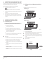
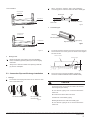
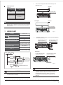
1
INSTALLATION
MANUAL
Wall-mounted Type
Digital Scroll and DC/AC Inverter Commercial Air-conditioner
The Digital Scroll and DC/AC Inverter share the same indoor units.
Thank you very much for purchasing our air conditioner,
please read this manual carefully and keep it for future reference.
CONTENTS
PAGE
PRECAUTIONS.......................................................................................1
INSTALLATION INFORMATION............................................................... 2
When installing the unit in a small room, take measures
against to keep refrigerant concentration from exceeding
allowable safety limits in the event of refrigerant leakage.
Contact the place of purchase for more information.
Excessive refrigerant in a closed ambient can lead to oxygen
deficiency.
ATTACHED FITTINGS............................................................................. 3
INSPECTING AND HANDLING THE UNIT................................................ 4
INDOOR UNIT INSTALLATION................................................................ 4
REFRIGERANT PIPE INSTALLATION....................................................... 6
WIRING CHART...................................................................................... 7
TEST OPERATION..................................................................................10
Use the attached accessories parts and specified parts
for installation.
otherwise, it will cause the set to fall, water leakage,
electrical shock fire.
Install at a strong and firm location which is able to
withstand the set' s weight.
If the strength is not enough or installation is not properly
done, the set will drop to cause injury.
The appliance must be installed 2.5m above floor.
The appliance shall not be installed in the laundry.
1.
PRECAUTIONS
Be sure to be in conformity with the local, national and
international laws and regulations.
Read "PRECAUTIONS" carefully before installation.
The following precautions include important safty items.
Observe them and never forget.
Keep this manual with the owner's manual in a handy place
for future reference.
The safty precautions listed here are divided into two categories. In
either case, important safty information is listed which must be read
carefully.
WARNING
Failure to observe a warning may result in death.
CAUTION
Failure to observe a caution may result in injury or damage
to the equipment.
After completing the installation, make sure that the unit operates
properly during the start-up operation. Please instruct the customer
on how to operate the unit and keep it maintained.Also, inform
customers that they should store this installation manual along with
the owner's manual for future reference.
WARNING
Be sure only trained and qualified service personnel to
install, repair or service the equipment.
Improper installation, repair, and maintenance may result in
electric shocks, short-circuit, leaks, fire or other damage to
the equipment.
Install according to this installation instructions strictly.
If installation is defective, it will cause water leakage, electric
shocks, fire.
Before obtaining access to terminals, all supply circuits
must be disconnected.
The appliance must be positioned so that the plug is
accessible.
The enclosure of the appliance shall be marked by word,
or by symbols, with the direction of the fluid flow.
For electrical work, follow the local national wiring
standard, regulation and this installation instructions. An
independent circuit and single outlet must be used.
If electrical circuit capacity is not enough or defect in
electrical work, it will cause electrical shock fire.
Use the specified cable and connect tightly and clamp
the cable so that no external force will be acted on the
terminal.
If connection or fixing is not perfect, it will cause heat-up or
fire at the connection.
Wiring routing must be properly arranged so that control
board cover is fixed properly.
If control board cover is not fixed perfectly, it will cause
heat-up at connection point of terminal, fire or electrical
shock.
If the supply cord is damaged, it must be replaced by the
manufacture or its sevice agent or similarly qualifued
person in order to avoid a hazard.
An all-pole disconnection switch having a cintract
separation of at least 3mm in a poles should be
connected in fixed wiring.
When carrying out piping connection, take care not to let
air substances go into refrigeration cycle.
Otherwise, it will cause lower capacity, abnormal high
pressure in the refrigeration cycle, explosion and injury.
Do not modify the length of the power supply cord or use
of extension cord, and do not share the single outlet with
other electrical appliances.
Otherwise, it will cause fire or electrical shock.
Carry out the specified installation work after taking into
account strong winds, typhoons or earthquakes.
Improper installation work may result in the equipment falling
and causing accidents.
installation manual
1
2.
If the refrigerant leaks during installation, ventilate the
area immediately.
Toxic gas may be produced if the refrigerant comes into the
place contacting with fire.
After completing the installation work, check that the
refrigerant does not leak.
Toxic gas may be produced if the refrigerant leaks into the
room and comes into contact with a source of fire, such as a
fan heater, stove or cooker.
INSTALLATION INFORMATION
To install properly, please read this "installation manual" at
first.
The air conditioner must be installed by qualified persons.
When installing the indoor unit or its tubing, please follow
this manual as strictly as possible.
If the air conditioner is installed on a metal part of the
building, it must be electrically insulated according to the
relevant standards to electrical appliances.
CAUTION
Ground the air conditioner.
Do not connect the ground wire to gas or water pipes,
lightning rod or a telephone ground wire.Incomplete
grounding may result in electric shocks.
Be sure to install an earth leakage breaker.
Failure to install an earth leakage breaker may result in
electric shocks.
When all the installation work is finished, please turn on the
power only after a thorough check.
Regret for no further announcement if there is any change
of this manual caused by product improvement.
INSTALLATION ORDER
Select the location;
Install the indoor unit;
Connect the outdoor unit wires , then connect the indoor
unit wires.
You are not allow to connect the air conditioner with the
power source until w(including
iring and piping the air conditioner is done.
Install the outdoor unit;
Install the connecting pipe ;
Connect the drain pipe;
While following the instructions in this installation
manual, install drain piping in order to ensure proper
drainage and insulate piping in order to prevent
condensation.
Improper drain piping may result in water leakage and
property damage.
Install the indoor and outdoor units, power supply wiring
and connecting wires at least 1 meter away from
televisions or radios in order to prevent image
interference or noise.
Depending on the radio waves, a distance of 1 meter may not
be sufficient enough to eliminate the noise.
The appliance is not intended for use by young children
or infirm persons without supervision.
Young children should be supervised to ensure that they
do not play with the appliance.
Don't install the air conditioner in the following locations:
There is petrolatum existing.
There is salty air surrounding (near the coast).
There is caustic gas (the sulfide, for example) existing in
the air (near a hot spring).
The Volt vibrates violently (in the factories).
In buses or cabinets.
In kitchen where it is full of oil gas.
There is strong electromagnetic wave existing.
There are inflammable materials or gas.
There is acid or alkaline liquid evaporating.
The appliance shall not be installed in the laundry.
Other special conditions.
installation manual
2
Wiring;
Test operation.
3.
ATTACHED FITTINGS
Please check whether the following fittings are of full scope. If there are some spare fittings , please restore them carefully.
NAME
SHAPE
1. Remote controller manual
QUANTITY
1
2. Screw ST3.9x25 for installation board
3
3. Plastic expanded tube
3
4. Wrapping tape
1
5.Drain pipe
1
6. Wall conduit cover
1
7. Remote controller
(including operation manual)
1
8. Frame
1
9. Mounting screw(ST2.9
10-C-H)
FUNCTION
2
Secure the installation board
Hold the remote controller
Insulation Holder for remote controller
10. Alkaline dry batteries (AM4)
2
11. Owner's manual
1
Not attach in several unit
12. Installation manual
1
This manual
13. Network matching wire
1
The indoor unit which at the terminal of
communication system should connect a
impedance between port P and port Q.
Cautions on remote controller installation:
Never throw or beat the controller.
Mounting screw B
ST2.9x10-C-H
Before installation, operate the remote controller to determine its location in a
reception range.
Keep the remote controller at least 1m apart from the nearest TV set or stereo
equipment. (it is necessary to prevent image disturbances or noise interferences.)
Do not install the remote controller in a place exposed to direct sunlight or close to a
heating source, such as a stove.
Note that the positive and negative poles are right positions when loading batteries.
This manual is subject to changes due to technological improvement without further
notices.
Remote controller
holder
Remote
controller
Fig.3-1
installation manual
3
4.
INSPECTING AND HANDLING THE UNIT
At delivery, the package should be checked and any damage should
be reported immediately to the carrier claims agent.
5.2 Drilling A Hole and Mounting Installation
Board
When handling the unit, take into account the following:
Installation Board and Its Direction (unit: mm)
Fragile, handle the unit with care.
22\28\36 type
Keep the unit upright in order to avoid compressor
damage.
Choose on before hand the path along which the unit is to be
brought in.
3
Move this unit as originally package as possible.
4
When lifting the unit , always use protectors to prevent belt
damage and pay attention to the position of the unit’s centre
of gravity.
460
290
2
mounting board of indoor unit
25
1
915
the shape of indoor unit
INDOOR UNIT INSTALLATION
45\56\71 type
mounting board of indoor unit
5.1 Installation place
460
316
Installation in the following places may cause trouble.If it
is unavoidable, please consult with the local dealer.
36
5.
Fig.5-1
A place full of machine oil.
A saline place such as coast.
1070
A place full of sulfide gas such as hot-spring resort.
the shape of indoor unit
Places where there are high frequency machines such
as wireless equipment, welding
Machine, and medical facility.
A place there is no combustive gases and volatile matter.
A place of special environmental conditions.
Indoor Unit
A place where is no obstacle near the inlet and outlet area.
A place which can bear the weight of the indoor unit.
1
Fig.5-2
Fix the installation board.
Install the installation board horizontally on structural parts in
the wall with the spaces provided around the plate.
In case of brick, concrete or similar type walls,make 5mmdia,
holes in the wall. Insert clip anchors for appropriate mounting
screws.
Fix the installation board on the wall.
Right installation
A place which allows the air filter to be removed.
A place where the reception range is not Exposed to direct
sunlight.
A place where the connective pipe and drain hose is easy
to led out.
mounting board
of indoor unit
horizontal line
A place 1m or more to TV, radio instrument, in the center of
the room is perfect.
The indoor unit should be installed 2.3 meters or more above
the floor.
installation manual
4
Fig.5-3
When connection extension drain hose,insulate the
connecting part of extension drain hose with a shield pipe
False installation
mounting board
of indoor unit
Shield pipe
Wall
horizontal line
Extension drainhose
Drain hose
Fig.5-6
2
mounting board
of indoor unit
Connection pipe
Left piping
Left back piping
horizontal line
Right back piping
Right piping
Fig.5-7
Fig.5-4
2
For the left-hand and rear-left-hand piping,install the piping as
shown. Bend the conn-ective pipe to be laid at 43mm height or
less from the wall.
Indoor unit outline
Drilling a hole.
Connective pipe
Always use a wall hole conduit when piercing metal lath,
ply wood or metal plate.
43
Determine the pipe hole position using the installation
board, and drill the pipehole (N95mm) so it slants slightly
downward.
.
.. .
. ..
.......................................................................................
. . . . .. . ... .. . .. .. ... .. . .
.......
............
Fig.5-8
5.3 Connective Pipe and Drainage Installation
1
Fix the end of the connective pipe.(Refer to Tightening
Connection in REFRI-GERANT PIPING CONNECTION)
Drainage
Run the drain hose sloping downward. Do not install the drain
hose as illustrated below.
CAUTION
Connect the indoor unit first then the outdoor unit and bend
and arrange the pipe carefully.
Do not allow the piping to let out from the back of the
indoor unit.
Be careful not to let the drain hose slack.
Do not form a rise
Do not put the hose
end into water
Fig.5-5
Insulate both of the auxiliary piping.
Banding the drain hose under the auxiliary pipe.
Do not allow the piping to let out from the back of the
indoor unit.
installation manual
5
3
6. REFRIGERANT PIPE INSTALLATION
Piping and bandaging
Wind the connective cable, drain hose and wiring with tape
securely, evenly as shown below.
Because the condensed water from rear of the indoor unit is
gathered in Pond Box and is piped out of room. Do not put
anything else in the box.
Indoor unit
Pipe room
.. . . . .
.. . . . .
. . . .. .
..
..
.
. ... .. . .
.
Ventilate the air if there was any refrigerant leakage during
installation.Leaked refrigerant will generate poisonous gas if
meeting fire.
Make sure there is no refrigerant leakage after installation.
.Leaked refrigerant will generate poisonous gas if meeting fire.
Pond box
Connective
cable
CAUTION
6.1 Allowed Length and Drop of Piping
Connective
pipe
Wrapping belt
Drain hose
Fig.5-9
Requirements are different when installing the Outdoor
Unit,Please refer to Outdoor Unit Installation Manual for
detailed information.
6.2 Material and Size of the Piping
Table 6-1
5.4 Indoor Unit Installation
Pipe Material
Copper Pipe for Air Conditioner
Model
Pass the piping through the hole in the wall.
Size(mm)
Put the claw at the back of the indoor unit on the hook of
the installation board, move the Indoor Unit from side to
side to see that it is securely hooked.
Piping can easily be made by lifting the indoor unit with
a cushioning material between the indoor unit and the
wall. Get it out after finish piping.
Push the lower part of the Indoor Unit up to the wall,Then
move the Indoor Unit from side to side, up and down to
check if it is hooked securely.
22/28/36/45
56/71
(Gas side)
Φ12.7
Φ15.9
(Liquid side)
Φ6.4
Φ9.5
6.3 Refrigerant Volume to Be Added
Refrigerant Volume to be added is calculated according to
Outdoor Unit Installation Manual .
Be save to add refrigerant measuring by a scale.
CAUTION
hooker
Cushioning
material
Fig.5-10
If refrigerant volume added is inadequate (too much or
insufficient),the compressor malfunction will be caused.Be
sure to calculate the refrigerant volume carefully.
The service man should note down the piping length and
refrigerant volume added on the nameplate, which is on the
Electric Control Box Cover of outdoor unit for to diagnose the
compressor when compressor malfunction occurs.
6.4 Connection of the Refrigerant Pipe
Connection of the refrigerant pipe should
be done by professionals.
Double-span should be used when
connecting pipesof Indoor Unit.
CAUTION
The temperature of refrigerant circuit will be high, please
keep the interconnection cable away from the copper tube.
installation manual
6
1
Take out the faceplate,then dismantle the display cover
plate.(see Fig.7-1)
Tightening Torque
faceplate
Table 6-2
Tightening Torque
(N.m)
Outer diameter(mm)
of connection piping
Φ6.4
14.2~17.2
Φ9.5
32.7~39.9
Φ12.7
49.5~60.3
Φ15.9
61.8~75.4
Φ19.1
97.2~118.6
display cover plate
faceplate
S faceplate
NOTE
Please refer to installation instructions for the refrigerant
piping conection of the air conditioner that with throttle
device inside.
wiring cover plate
7. WIRING CHART
Fig.7-1
Model(W)
2200~7100
Phase
Power
1-Phase
Frequency and volt
220-240V~ 50/60Hz
Manual switch/Insurance (A)
Indoor unit power wiring
15/15
3x2.5
(mm2)
2
Individual connect the power cord and signal line,adjust the
dial switch.(see Fig.7-2)
the wire holder of power
cord(three-position))
the wire holder of signal
line (five-position))
2x4.0+1x2.5
(Add eletrical auxiliary heat)
Indoor/outdoor connectingwiring
(mm2) (Electric signal)
Fuse (A)
display cover plate
3x0.75(3x0.75)
5A
dial switch
8A
(Add eletrical auxiliary heat)
S faceplate
Power (220-240V~50/60Hz)
the wire holder of power
cord(three-position))
the wire holder of signal
line (five-position))
wiring cover plate
INDOOR UNIT
CENTRAL CONTROL
MONITOR(CCM)
COMPUTER
INDOOR UNIT
OUTDOOR UNIT
dial switch
Fig.7-2
INDOOR UNIT
the shielded twisted-pair wire
CAUTION
CAUTION
The reserved function is indicated in broken line table,users
can select it when necessary.
An all-pole disconnection device which has at least 3mm
separation distance in all pole and a residual current
device(RCD)with the rating of above 10mA shall be
incorporated in the fixed wiring according to the national rule.
installation manual
7
7.2 Horsepower set
7.1 Terminal Board Diagram
Please refer to the indoor unit wiring diagram for the wiring.
Horsepower code
PO WER_S
NOTE
EF 0
ABC
123 4
D
56
The air-conditioners can connect with Central Control Monitor
(CCM). Before operation, please wiring correctly and set system
address and network address of indoor units.
789
ENC1
Single phase indoor unit
RED
BLACK
ENC1
Y/G
Note: The horsepower
has been set before
leaving the factory ,
anyone can’t
modify it except the
maintenance person.
Y/G
RED
BLACK
L N
XT1
X
Y (E)
To central control
Monitor (CCM)
COMM. BUS
P
Q
To outdoor
COMM. BUS
DISPLAY BOARD
WIRE CONTROLLER
To wire controller
The reserved wire control function is indicated in broken
line table,users can purchase the wire controller when
necessary.
8
Code
Capacity(Horsepower)
0
2200W(0.8HP)
1
2800W(1.0HP)
2
3600W(1.2HP)
3
4500W(1.5HP)
4
5600W(2.0HP)
5
7100W(2.5HP)
(E)
Please adopt the shielded twisted-pair wire,
and connect the shielded layed to (E)
installation manual
For set horsepower
BLA CK
GRAY
YELL OW
BLA CK
BLU E
WHIT E
INDOOR UNIT POWER
220-240V~50/60Hz
Toggle switch
CAUTION
The system together have 64units(0-63),everyone has only
system addresscode,If two addresses are the same in one
system , the abnormal operation will occur.
Please switch off the power before setting,otherwise the
unexpected error will occur.
7.3 Network address set
1) Network address is set by communication of indoor and
outdoor unit; the address is the same as indoor address, there
is no need to set separately.
2) The central control of indoor units can be done on outdoor
unit, there is no need to control indoor unit separately, for
details please refer to V4+ outdoor unit manual.
3) For previous control of indoor units, the network can be set
by connecting (X,Y,E) terminals, there is no need to set
network address. The network can also be set by outer
network module and main board (CN20).
7.4 Main board Code designation
SW1 definition
ON
ON
ON
SW1
1234
SW1
1234
SW1
● 1 means factory test mode
● 0 means add. auto searching mode
ON
(default setting)
● 1 means DC fan Is chosen
● 0 means AC fan Is chosen
SW1
1234
ON
SW1
● 10 means DC fan static pressure is 2
1234
● 00 means DC fan static pressure is 0
(reserved)
● 01 means DC fan static pressure is 1
(reserved)
ON
1234
SW1
1234
(reserved)
● 11 means DC fan static pressure is 3
(reserved)
SW2 definition
ON
ON
ON
ON
SW2
1234
SW2
1234
SW2
1234
SW2
1234
● 00 means the temperature is 15
degrees when shutting down the unit
for cold wind proof.
● 01 means the temperature is 20
degrees when shutting down the
unit for cold wind proof.
● 10 means the temperature is 24
degrees when shutting down the
unit for cold wind proof.
● 11 means the temperature is 26
degrees when shutting down the
unit for cold wind proof.
ON
SW2
● 00 means the time of stopping
1234
ON
SW2
TERMAL fan is 4 minutes
● 01 means the time of stopping
TERMAL fan is 8 minutes
1234
ON
ON
SW2
● 10 means the time of stopping
TERMAL fan is 12 minutes
1234
SW2
1234
● 11 means the time of stopping
TERMAL fan is 16 minutes
SW5 definition
ON
S W5
● 00 means temperature compensation is
6 degrees under heating mode
ON
1 2
ON
● 01 means temperature compensation is
2 degrees under heating mode
ON
ON
1 2 3
SW6
1 2 3
ON
SW6
is 4 degrees under heating mode
ON
SW5
● 11 means temperature compensation
is 8 degrees under heating mode
1 2
J1,J2 definition
SW6 definition
SW6
● 10 means temperature compensation
1 2
S W5
1 2
SW5
J1
● 1 means old display panel
J1 no Jumpers means power
off memory function
● 0 means new display panel
J1
J1 Jumpers means no power
off memory function
● 1 means auto wind under auto mode
● 0 means auto wind under non auto mode
J2
reserved
reserved
1 2 3
installation manual
9
SW7 definition
ON
SW7
According to the user’s requirement, install the remote controller
frame where the remote controller’s signal can reach the indoor
unit smoothly.
Standard configure
1 2
ON
SW7
●
Last one in the network
●
1 2
Test operation
Set the air conditioner under the mode of “COOLING”with the
remote controller, and check the following points per the
“Owner’s Manual”If there is any malfunction, please resolve it
through chapter “Troubles And Causes ”.
The indoor unit
0/1 definition
ON
Means 0
ON
Means 1
8 TEST OPERATION
●
Whether the switch on the remote controller works well.
●
Whether the buttons on the remote controller works well.
●
Whether the air flow louver moves normally.
●
Whether the room temperature is adjusted well.
●
Whether the indicator lights normally.
●
Whether the temporary buttons works well.
●
Whether the drainage is normal.
●
Whether there is vibration or abnormal noise during operation.
●
Whether the air conditioner heats well in the case of the
HEATING/COOLING type.
CAUTION
The outdoor unit
Protection function will delay the startup of compressor for 3
minutes in case the unit is turned on immediately after power on or restarted after shutdown.
The test operation must be carried out after the entire installation
has been completed.
Please confirm the following points before the test operation:
●
The indoor unit and outdoor unit are installed properly.
●
Tubing and wiring are correctly completed.
●
The refrigerant pipe system is leakage-checked.
●
The drainage is unimpeded.
●
The heating insulation works well.
●
The ground wiring is connected correctly.
●
The length of the tubing and the added stow capacity of the
refrigerant have been recorded.
●
The power voltage fits the rated voltage of the air conditioner.
●
There is no obstacle at the outlet and inlet of the outdoor and
indoor and indoor units.
●
The gas-side and liquid-side stop values are both opened.
●
The air conditioner is pre-heated by turning on the power.
installation manual
10
●
Whether there is vibration or abnormal noise during operation.
●
Whether the generated wind, noise, or condensed water by the
air conditioner have influenced your neighborhood.
●
Whether any of the refrigerant is leaked.
MDV10I-018CW
202000171518