1
AKD™, AKD™ BASIC, AKD™ PDMM
Installation Manual
Edition: M, September 2013
Valid for AKD, AKD BASIC Hardware Revision D
Valid for AKD BASIC-I/O Hardware Revision DA
Valid for AKD PDMM Hardware Revision DB
Part Number 903-200003-00
Original Document
Keep all manuals as a product component during the life span of the product.
Pass all manuals to future users and owners of the product.
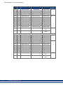
Record of Document Revisions
Revision
Remarks
Table with lifecycle information of this document see "Record of document revisions" (➜ p.
193)
...
K, 11/2012
Feedback wiring diagrams updated, font size hint, fault tables updated, regen fusing
L, 05/2013
Hiperface DSL Feedback new (from FW 1.9), fault tables updated, KCM module added
M, 09/2013
24A AKD-M added, fault tables update, outer dimensions updated
Hardware Revision (HR)
AKD
A
AKD-M
-
AKD-T-IC
-
Firmware
from 1.3
WorkBench
from 1.3
C
-
-
from 1.5
from 1.5
D
DB
DA
from 1.6
from 1.6
KAS IDE Remarks
AKD Start revision
-
STO certified, PROFINET RT
released
from 2.5
Control board revision 9, AKD
PDMM Start revision, AKD
BASIC-IC Start revision
Trademarks
l
l
l
l
l
l
l
l
l
AKD is a registered trademark of Kollmorgen Corporation
EnDat is a registered trademark of Dr. Johannes Heidenhain GmbH
EtherCAT is a registered trademark and patented technology, licensed by Beckhoff Automation GmbH
Ethernet/IP is a registered trademark of ODVA, Inc.
Ethernet/IP Communication Stack: copyright (c) 2009, Rockwell Automation
HIPERFACE is a registered trademark of Max Stegmann GmbH
PROFINET is a registered trademark of PROFIBUS and PROFINET International (PI)
SIMATIC is a registered trademark of SIEMENS AG
Windows is a registered trademark of Microsoft Corporation
Current patents
l
l
l
l
l
US Patent 5,162,798 (used in control card R/D)
US Patent 5,646,496 (used in control card R/D and 1 Vp-p feedback interface)
US Patent 6,118,241 (used in control card simple dynamic braking)
US Patent 8,154,228 (Dynamic Braking For Electric Motors)
US Patent 8,214,063 (Auto-tune of a Control System Based on Frequency Response)
Technical changes which improve the performance of the device may be made without prior notice!
Printed in the United States of America
This document is the intellectual property of Kollmorgen. All rights reserved. No part of this work may be reproduced in any form (by photocopying, microfilm or any other method) or stored, processed, copied or distributed
by electronic means without the written permission of Kollmorgen.
2
Kollmorgen | September 2013
AKD Installation | Table of Contents
1 Table of Contents
1 Table of Contents
2 General
3
9
2.1 About this Manual
10
2.2 Using the PDF Format
10
2.3 Notes for the printed edition (paper version)
10
2.4 Symbols Used
11
2.5 Abbreviations Used
12
2.6 Standards Used
13
14
3 Safety
3.1 You should pay attention to this
15
3.2 Use as Directed
17
3.3 Prohibited Use
17
3.4 Handling
18
3.4.1 Transport
18
3.4.2 Packaging
18
3.4.3 Storage
18
3.4.4 Maintenance and Cleaning
19
3.4.5 Uninstalling
19
3.4.6 Repair and Disposal
19
4 Approvals
20
4.1 Conformance with UL/cUL
21
4.1.1 UL Markings
21
4.2 CE Conformance
22
4.2.1 European Directives and Standards for the Machine Builder
23
4.2.2 EC Declaration of Conformity
24
4.3 Safe Torque Off (STO)
25
5 Package
26
5.1 Package Supplied
27
5.2 Nameplate
27
5.3 Part Number Scheme
28
6 Technical description and data
29
6.1 The AKD Family of Digital Drives
30
6.2 Ambient Conditions, Ventilation, and Mounting Position
32
6.3 Mechanical Data
32
6.4 Inputs/Outputs
33
6.5 Electrical Data AKD-xzzz06
34
6.6 Electrical Data AKD-xzzz07
35
6.7 Performance Data
36
6.8 Recommended Tightening Torques
36
6.9 Fusing
37
6.9.1 External power supply fusing
37
6.9.2 External 24 V supply fusing
37
6.9.3 External regen resistor fusing
37
Kollmorgen | September 2013
3
AKD Installation | Table of Contents
6.10 Grounding System
37
6.11 Connectors
38
6.12 Cable and Wire Requirements
39
6.12.1 General
39
6.12.2 Cable cross sections and requirements
39
6.13 Dynamic Braking
40
6.13.1 Regen circuit
40
6.13.1.1 Functional description
40
6.13.1.2 Technical data for AKD-xzzz06
41
6.13.1.3 Technical data for AKD-xzzz07
42
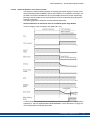
6.14 Switch-On and Switch-Off Behavior
6.14.1 Switch-on behavior in standard operation
44
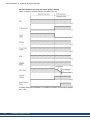
6.14.2 Switch-off behavior
45
6.14.2.1 Switch-off behavior using the DRV.DIS command
45
6.14.2.2 Switch-off behavior using a digital input (controlled stop)
46
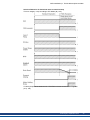
6.14.2.3 Switch-off behavior using HW Enable input (uncontrolled stop)
46
6.14.2.4 Switch-off behavior in the event of a fault
47
6.15 Stop / Emergency Stop / Emergency Off
50
6.15.1 Stop
50
6.15.2 Emergency Stop
51
6.15.3 Emergency Off
51
6.16 Safe Torque Off (STO)
52
6.16.1 Safety characteristic data
52
6.16.2 Use as directed
52
6.16.3 Prohibited use
52
6.16.4 Safety instructions
53
6.16.5 Technical data and pinning
54
6.16.6 Enclosure, wiring
54
6.16.7 Functional description
54
6.16.7.1 Signal diagram (sequence)
55
6.16.7.2 Functional test
55
6.16.7.3 Control circuit (example)
56
6.16.7.4 Mains supply circuit (example)
57
6.17 Shock-hazard Protection
58
6.17.1 Leakage current
58
6.17.2 Residual current protective device (RCD)
58
6.17.3 Isolating transformers
58
7 Mechanical Installation
59
7.1 Important Notes
60
7.2 Guide to Mechanical Installation
60
7.3 Mechanical Drawings Standard Width
61
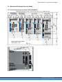
7.3.1 Control cabinet layout AKD-xzzz06, standard width
61
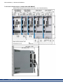
7.3.2 Control cabinet layout AKD-xzzz07, standard width
62
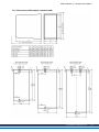
7.3.3 Dimensions AKD-xzzz06, standard width
63
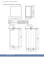
7.3.4 Dimensions AKD-xzzz07, standard width
64
7.4 Mechanical Drawings Extended Width
4
43
Kollmorgen | September 2013
65
AKD Installation | Table of Contents
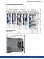
7.4.1 Control cabinet layout, example with AKD-M00306
65
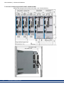
7.4.2 Control cabinet layout, example with AKD-M00307
66
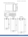
7.4.3 Dimensions AKD-xzzz06, extended width
67
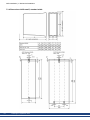
7.4.4 Dimensions AKD-xzzz07, extended width
68
69
8 Electrical Installation
8.1 Important Notes
70
8.2 Guide to electrical installation
71
8.3 Wiring
72
8.4 Components of a servosystem
73
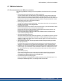
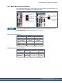
8.5 Connection Overview AKD-B, AKD-P, AKD-T
75
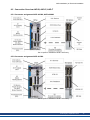
8.5.1 Connector assignment AKD-x00306, AKD-x00606
75
8.5.2 Connector assignment AKD-x01206
75
8.5.3 Connector assignment AKD-x02406 and AKD-xzzz07
76
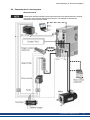
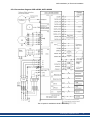
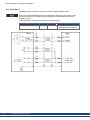
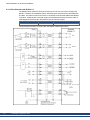
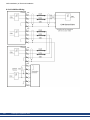
8.5.4 Connection diagram AKD-x00306, AKD-x00606
77
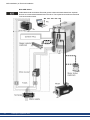
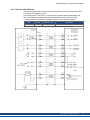
8.5.5 Connection diagram AKD-x01206
78
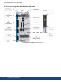
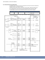
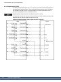
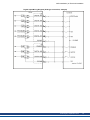
8.5.6 Connection diagram AKD-x02406 and AKD-xzzz07
79
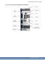
8.6 Connection Overview AKD-M
80
8.6.1 Connector assignment AKD-M00306, AKD-M00606
80
8.6.2 Connector assignment AKD-M01206
80
8.6.3 Connector assignment AKD-M02406 and AKD-Mzzz07
81
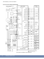
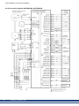
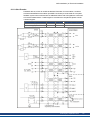
8.6.4 Connection diagram AKD-M00306, AKD-M00606
82
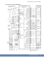
8.6.5 Connection diagram AKD-M01206
83
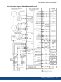
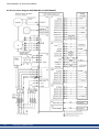
8.6.6 Connection diagram AKD-M02406 and AKD-Mzzz07
84
8.7 EMI Noise Reduction
85
8.7.1 Recommendations for EMI noise reduction
85
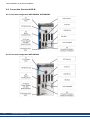
8.7.2 Shielding with external shielding busbar
86
8.7.2.1 Shielding Concept
86
8.7.2.2 Shielding Busbar
87
8.7.3 Shielding connection to the drive
88
8.7.3.1 Grounding plates
88
8.7.3.2 Shield connection clamps
88
8.7.3.3 Motor connector X2 with shielding connection
88
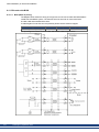
8.8 Electrical Supply Connection
89
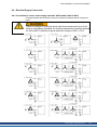
8.8.1 Connection to various mains supply networks AKD-xzzz06 (120V to 240V)
89
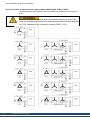
8.8.2 Connection to various mains supply networks AKD-xzzz07 (240V to 480V)
90
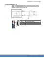
8.8.3 24 V auxiliary supply (X1)
91
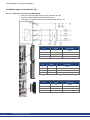
8.8.4 Mains supply connection (X3, X4)
92
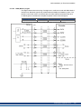
8.8.4.1 Three phase connection (all AKD types)
92
8.8.4.2 Single phase connection (AKD-x00306 to AKD-x01206 only)
93
8.9 DC Bus link (X3)
94
8.9.1 External regen resistor (X3)
95
8.9.2 Capacitor Modules (X3)
96
8.9.2.1 Technical Data
96
8.9.2.2 Example installation with KCM-S and KCM-E
97
8.9.2.3 Example installation with KCM-P and KCM-E
98
8.9.2.4 Discharging KCM modules
99
Kollmorgen | September 2013
5
AKD Installation | Table of Contents
8.10 Motor Connection
100
8.10.1 Motor power (X2)
101
8.10.1.1 Cable length ≤ 25 m
101
8.10.1.2 Cable length >25 m
101
8.10.2 Motor holding brake (X2)
102
8.11 Feedback Connection
104
8.11.2 Resolver
105
8.11.3 SFD Gen 2
106
8.11.4 Hiperface DSL
107
8.11.5 Encoder with BiSS
108
8.11.5.1 BiSS (Mode A) analog
108
8.11.5.2 BiSS (Mode C) digital
109
8.11.6 Sine Encoder with EnDat 2.1
110
8.11.7 Encoder with EnDat 2.2
111
8.11.8 Sine Encoder with Hiperface
112
8.11.9 Sine Encoder
113
8.11.10 Incremental Encoder
114
8.11.11 Tamagawa Smart Abs Encoder
115
8.12 Electronic gearing, Master-slave operation
8.12.1 Technical characteristics and pinout
116
116
8.12.1.1 Connector X7 Input
116
8.12.1.2 Connector X9 Input
117
8.12.1.3 Connector X9 Output
117
8.12.2 Command encoder signal connection
118
8.12.2.1 Incremental encoder input 5 V (X9)
118
8.12.2.2 Incremental encoder input 24 V (X7)
118
8.12.2.3 Encoder with EnDat 2.2 input 5 V (X9)
119
8.12.3 Pulse / Direction signal connection
120
8.12.3.1 Pulse / Direction input 5 V (X9)
120
8.12.3.2 Pulse / Direction Input 5V (X7)
120
8.12.4 Up / Down signal connection
121
8.12.4.1 Up / Down input 5 V (X9)
121
8.12.4.2 Up / Down input 24 V (X7)
121
8.12.5 Emulated Encoder Output (EEO)
122
8.12.6 Master-Slave control
123
8.13 I/O Connection
6
103
8.11.1 Feedback connector (X10)
124
8.13.1 I/O connectors X7 and X8 (all AKD variants)
124
8.13.2 I/O connectors X21, X22, X23 and X24 (AKD-T with I/O option card only)
125
8.13.3 I/O connectors X35 and X36 (AKD-M only)
127
8.13.4 Analog Input (X8, X24)
128
8.13.5 Analog Output (X8, X23)
129
8.13.6 Digital Inputs (X7/X8)
130
8.13.6.1 Digital Inputs 1 and 2
132
8.13.6.2 Digital Inputs 3 to 7
132
8.13.6.3 Digital Input 8 (ENABLE)
132
Kollmorgen | September 2013
AKD Installation | Table of Contents
8.13.7 Digital Outputs (X7/X8)
133
8.13.7.1 Digital Outputs 1 and 2
133
8.13.7.2 FAULT relay contacts
134
8.13.8 Digital Inputs with I/O option (X21, X22)
135
8.13.9 Digital Outputs with I/O option (X23/X24)
137
8.13.9.1 Digital Outputs 21 to 24, 26 to 29
137
8.13.9.2 Digital Relay Outputs 25, 30
138
8.13.10 Digital Inputs (X35/X36) with AKD-M
139
8.13.11 Digital Outputs (X35/X36) with AKD-M
141
8.13.11.1 Digital Outputs 21 and 22
141
8.14 LED display
142
8.15 Rotary Switches (S1, S2, RS1)
143
8.15.1 Rotary switches S1 and S2 with AKD-B, -P, -T
143
8.15.2 Rotary switch RS1 with AKD-M
143
8.16 Pushbuttons (B1, B2, B3)
144
8.16.1 Pushbutton B1 with AKD-B, -P, -T
144
8.16.2 Pushbuttons B1, B2, B3 with AKD-M
145
8.17 SD Card Slot
146
8.17.1 SD Card Slot with I/O option card
146
8.17.2 SD Card Slot with AKD-M
147
8.18 Service Interface (X11, X32)
148
8.18.1 Pinout X11, X32
148
8.18.2 Service Bus Protocols X11, X32
148
8.18.3 Possible Network Configurations
148
8.18.4 Setting the IP AddressAKD-B, AKD-P, AKD-T
149
8.18.5 Setting the IP Address AKD-M
151
8.18.6 Modbus TCP
152
8.19 CAN-Bus Interface (X12/X13)
152
8.19.1 CAN-Bus activation with AKD-CC models
153
8.19.2 Baudrate for CAN-Bus
154
8.19.3 Node Address for CAN-Bus
155
8.19.4 CAN-Bus Termination
155
8.19.5 CAN-Bus Cable
155
8.19.6 CAN-Bus Wiring
156
8.20 Motion Bus Interface (X5/X6/X11)
157
8.20.1 Pinout X5, X6, X11
157
8.20.2 Bus Protocols X5, X6, X11
157
8.20.3 EtherCAT
158
8.20.3.1 EtherCAT activation with AKD-CC models
158
8.20.4 SynqNet
159
8.20.5 PROFINET
159
8.20.6 Ethernet/IP
159
9 Setup
160
9.1 Important Notes
161
9.2 Setup AKD-B, AKD-P, AKD-T
162
9.2.1 Setup software WorkBench
162
Kollmorgen | September 2013
7
AKD Installation | Table of Contents
9.2.2 Use as directed
162
9.2.3 Software description
163
9.2.4 Hardware requirements
163
9.2.5 Operating systems
163
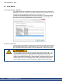
9.2.6 Installation under Windows 2000/XP/VISTA/7
164
9.2.7 Initial Drive Test AKD-B, AKD-P, AKD-T
165
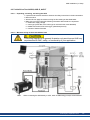
9.2.7.1 Unpacking, mounting, and wiring the AKD
165
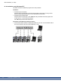
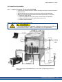
9.2.7.2 Minimum wiring for drive test without load
165
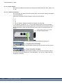
9.2.7.3 Set IP address
166
9.2.7.4 Confirm connections
166
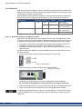
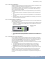
9.2.7.5 Install and start WorkBench
167
9.2.7.6 Set drive IP address in WorkBench
167
9.2.7.7 Enable the drive using the setup wizard
167
9.3 Setup AKD-M
168
9.3.2 Use as directed
168
9.3.3 Software description
169
9.3.4 Hardware requirements
169
9.3.5 Operating systems
169
9.3.6 Installation under Windows XP/7
170
9.3.7 Initial Drive Test AKD-M
171
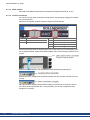
9.3.7.1 Unpacking, mounting, and wiring the AKD PDMM
171
9.3.7.2 Minimum wiring for drive test without load
171
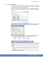
9.3.7.3 Set IP address
172
9.3.7.4 Confirm connections
172
9.3.7.5 Install and start KAS IDE
173
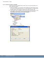
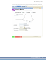
9.3.7.6 Set drive IP address in KAS IDE
174
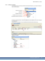
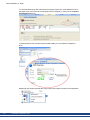
9.3.7.7 Starting new project
175
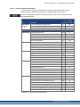
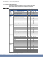
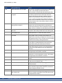
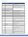
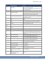
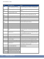
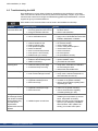
9.4 Fault and Warning Messages
178
9.4.1 Fault and warning messages AKD
178
9.4.2 Additional fault messages AKD-T
186
9.4.3 Additional error and alarm messages AKD-M
188
9.4.3.1 Errors
188
9.4.3.2 Alarms
190
9.5 Troubleshooting the AKD
10 Record of document revisions
11 Index
8
168
9.3.1 Setup software KAS IDE
Kollmorgen | September 2013
192
193
195
AKD Installation | 2 General
2 General
2.1 About this Manual
10
2.2 Using the PDF Format
10
2.3 Notes for the printed edition (paper version)
10
2.4 Symbols Used
11
2.5 Abbreviations Used
12
2.6 Standards Used
13
Kollmorgen | September 2013
9
AKD Installation | 2 General
2.1 About this Manual
This manual, AKD Installation Manual ("Instructions Manual" according to EC Machinery
Directive 2006/42/EC), describes the AKD series of digital drives drive and includes information needed to safely install an AKD. A digital version of this manual (pdf format) is available on the DVD included with your drive. Manual updates can be downloaded from the
Kollmorgen website (www.kollmorgen.com).
Additional documents include the following:
l
l
l
l
l
l
l
User Guide: describes how to use your drive in common applications. It also provides tips
for maximizing your system performance with the AKD. The User Guide includes the
Parameter and Command Reference Guide which provides documentation for the parameters and commands used to program the AKD.
CAN-BUS Communication: describes how to use your drive in CANopen applications.
EtherCAT Communication: describes how to use your drive in EtherCAT applications.
Ethernet/IP Communication: describes how to use your drive in Ethernet/IP applications.
PROFINET RT Communication: describes how to use your drive in PROFINET RT applications.
SynqNet Communication: describes how to use your drive in SynqNet applications.
Accessories Manual.It provides documentation for accessories like cables and regen
resistors used with AKD. Regional variants of this manual exist.
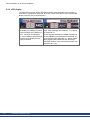
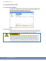
2.2 Using the PDF Format
This document includes several features for ease of navigation
Cross References
Table of contents and index include active cross references.
Table of contents and index
Lines are active cross references. Click on the line
and the appropriate page is accessed.
Page/chapter numbers in the text
Page/chapter numbers with cross references are
active links.
2.3 Notes for the printed edition (paper version)
A printed version of the manual is enclosed with each product. For environmental reasons,
the document was reduced in size and printed on DIN A5.
Should you experience difficulties reading the font size of the
scaled-down printed version, you can print and use the PDF version in DIN A4 format 1:1. You can find the PDF version on the
DVD accompanying the product and on the Kollmorgen website.
10
Kollmorgen | September 2013
AKD Installation | 2 General
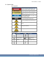
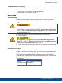
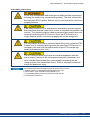
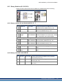
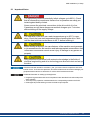
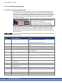
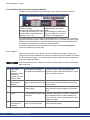
2.4 Symbols Used
Warning Symbols
Symbol
Indication
Indicates a hazardous situation which, if not
avoided, will result in death or serious injury.
Indicates a hazardous situation which, if not
avoided, could result in death or serious injury.
Indicates a hazardous situation which, if not
avoided, could result in minor or moderate
injury.
This is not a safety symbol.
Indicates situations which, if not avoided, could
result in property damage.
This is not a safety symbol.
This symbol indicates important notes.
Warning of a danger (general). The type of
danger is specified by the text next to the symbol.
Warning of danger from electricity and its
effects.
Warning of hot surfaces
Warning of suspended loads.
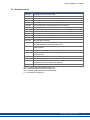
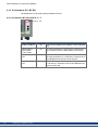
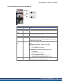
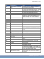
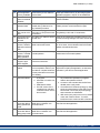
Drawing symbols
Symbol
Description
Signal ground
Symbol
Description
Diode
Chassis ground
Relays
Protective earth
Relays switch off
delayed
Resistor
Normal open contact
Fuse
Normal closed contact
Kollmorgen | September 2013
11
AKD Installation | 2 General
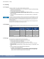
2.5 Abbreviations Used
12
Abbreviation
AGND
Meaning
Analog ground
CE
Communité Européenne
COM
Serial interface for a personal computer
DCOMx
Communication line for digital inputs (with x=7 or 8)
Disk
Magnetic storage (diskette, hard disk)
EEPROM
Electrically erasable programmable memory
EMC
Electromagnetic compatibility
F-SMA
Fiber optic cable connector according to IEC 60874-2
KAS
Kollmorgen Automation Suite
KAS IDE
Setup software (Kollmorgen Automation Suite Integrated Development Environment) used for AKD PDMM drives
LED
Light-emitting diode
LSB
Low significant byte (or bit)
MSB
Main significant byte (or bit)
NI
Zero pulse
PC
Personal computer
PE
Protective earth
PLC
Programmable logic control
PWM
Pulse-width modulation
RAM
Random access memory (volatile memory)
RBrake/RB
Regen resistor (also called a brake resistor)
RBext
External regen resistor
RBint
Internal regen resistor
RCD
Residual current device
RES
Resolver
ROD
Incremental encoder (A quad B)
S1
Continuous operation
STO
Safe torque off
VAC
Volts, alternating current
VDC
Volts, direct current
Kollmorgen | September 2013
AKD Installation | 2 General
2.6 Standards Used
Standard
ISO 4762
Content
Hexagon socket head cap screws
ISO 11898
Road vehicles — Controller area network (CAN)
ISO 12100
Safety of machinery: Basic concepts, general principles for design
ISO 13849
Safety of machinery: Safety-related parts of control systems
IEC 60085
Electrical insulation - Thermal evaluation and designation Maintenance
IEC 60204
Safety of Machinery: Electrical equipment of machinery
IEC 60364
Low-voltage electrical installations
IEC 60439
Low-Voltage Switchgear and Controlgear Assemblies
IEC 60529
International protection rating (IP code)
IEC 60664
Insulation coordination for equipment within low-voltage systems
IEC 60721
Classification of environmental conditions
IEC 61000
Electromagnetic compatibility (EMC)
IEC 61131
Programmable controllers
IEC 61491
Electrical equipment of industrial machines – Serial data link for real-time
communications between controls and drives.
IEC 61508
Functional safety of electrical/electronic/programmable electronic safetyrelated systems
IEC 61800
Adjustable speed electrical power drive systems
IEC 62061
Functional safety of electrical/electronic/programmable electronic safetyrelated systems
IEC 82079
Preparation of instructions for use - Structuring, content and presentation
ANSI Z535
Product safety (symbols, colors, information)
UL 840
UL Standard for Safety for Insulation Coordination Including Clearances and
Creepage Distances for Electrical Equipment
UL 508C
UL Standard for Safety Power Conversion Equipment
ANSI - American National Standard Institute, Inc.
IEC - International Electrotechnical Commission
ISO - International Organization for Standardization
UL - Underwriters Laboratories
Kollmorgen | September 2013
13
AKD Installation | 3 Safety
3 Safety
14
3.1 You should pay attention to this
15
3.2 Use as Directed
17
3.3 Prohibited Use
17
3.4 Handling
18
Kollmorgen | September 2013
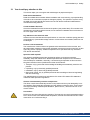
AKD Installation | 3 Safety
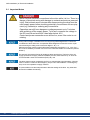
3.1 You should pay attention to this
This section helps you to recognize and avoid dangers to people and objects.
Read the documentation!
Read the available documentation before installation and commissioning. Improper handling
of the drive can cause harm to people or damage to property. The operator of systems using
the AKD must require that all personnel who work with the drive read and understand the
manual before using the drive.
Check Hardware Revision!
Check the Hardware Revision Number of the product (see product label). This number is the
link between your product and the manual, it must match the Hardware Revision Number on
the cover page of the manual.
Pay attention to the technical data!
Adhere to the technical data and the specifications on connection conditions (rating plate and
documentation). If permissible voltage values or current values are exceeded, the drives can
be damaged.
Perform a risk assessment!
The manufacturer of the machine must generate a risk assessment for the machine, and
take appropriate measures to ensure that unforeseen movements cannot cause injury or damage to any person or property. Additional requirements on specialist staff may also result
from the risk assessment.
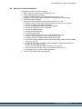
Specialist staff required!
Only properly qualified personnel are permitted to perform such tasks as transport,
assembly, setup and maintenance. Qualified specialist staff are persons who are familiar
with the transport, installation, assembly, commissioning and operation of drives and who
bring their relevant minimum qualifications to bear on their duties:
l
l
l
l
Transport: only by personnel with knowledge of handling electrostatically sensitive components.
Unpacking: only by electrically qualified personnel.
Installation: only by electrically qualified personnel.
Basic tests / Setup: only by qualified personnel with knowledge of electrical engineering
and drive technology
The qualified personnel must know and observe ISO 12100 / IEC 60364 / IEC 60664 and
national accident prevention regulations.
Observe electrostatically sensitive components!
The drives contain electrostatically sensitive components which may be damaged by incorrect handling. Electrostatically discharge your body before touching the drive. Avoid contact
with highly insulating materials (artificial fabrics, plastic film etc.). Place the drive on a conductive surface.
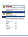
Hot surface!
Drives may have hot surfaces during operation. The heat sink can reach temperatures above
80°C. Risk of minor burns! Measure the temperature, and wait until the heat sink has cooled
down below 40 °C before touching it.
Kollmorgen | September 2013
15
AKD Installation | 3 Safety
Earthing!
It is vital that you ensure that the drive is safely earthed to the PE (protective earth) busbar in
the switch cabinet. Risk of electric shock. Without low-resistance earthing no personal protection can be guaranteed.
High voltages!
The equipment produces high electric voltages up to 900V. Do not open or touch the equipment during operation. Keep all covers and cabinet doors closed.
During operation, drives may have uncovered live sections, according to their level of enclosure protection. Wait at least seven minutes after disconnecting the drive from the main
supply power before touching potentially live sections of the equipment (such as contacts) or
removing any connections.
Capacitors can have dangerous voltages present up to seven minutes after switching off the
supply power. Always measure the voltage in the DC bus link and wait until the voltage is
below 40 V before handling components.
Never undo any electrical connections to the drive while it is live. There is a danger of electrical arcing with damage to contacts and personal injury.
Never modify the drive!
It is not allowed to modify the drive without permission by the manufacturer. Opening the
housing causes loss of warranty.
16
Kollmorgen | September 2013
AKD Installation | 3 Safety
3.2 Use as Directed
Drives are components that are built into electrical plants or machines and can only be operated as integral components of these plants or machines. The manufacturer of the machine
used with a drive must generate a risk assessment for the machine and take appropriate
measures to ensure that unforeseen movements cannot cause personnel injury or property
damage.
Cabinet and wiring
Drives must only be operated in a closed control cabinet suitable for the ambient conditions
➜ p. 29. Ventilation or cooling may be necessary to keep the temperature within the cabinet
below 40 °C.
Use only copper conductors for wiring. The conductor cross-sections can be derived from
the standard IEC 60204 (alternatively for AWG cross-sections: NEC Table 310-16, 75 °C column).
Power supply
The drives can be supplied by 1 or 3 phase industrial supply networks.
Drives in the AKD series can be supplied as follows:
l
l
AKD-xzzz06: 1 or 3 phase industrial supply networks
(not more than 200 kA symmetrical rated current at 120 V and 240 V).
AKD-xzzz07: 3 phase industrial supply networks
(not more than 200 kA symmetrical rated current at 240 V, 400 V and 480 V).
Connection to other voltage types of supply networks is possible with an additional isolating
transformer (➜ p. 89).
Periodic overvoltages between phases (L1, L2, L3) and the housing of the drive must not
exceed 1000 V peak. In accordance with IEC 61800, voltage spikes (< 50 µs) between
phases must not exceed 1000 V. Voltage spikes (< 50 µs) between a phase and the housing
must not exceed 2000 V.
EMC filter measures for AKD-xzzz06 must be implemented by the user.
Motor voltage rating
The AKD family of drives is exclusively intended for driving suitable synchronous servomotors with closed-loop control of torque, speed, and/or position. The rated voltage of the
motors must be at least as high as the DC bus link voltage divided by √2 produced by the
drive (UnMotor >=UDC/√2).
Safe torque off
Review the section "Use as Directed" in the STO chapter (➜ p. 52) before using this safety
function (according to ISO 13849 category 3).
3.3 Prohibited Use
Other use than that described in chapter “Use as directed” is not intended and can lead to personnel injuries and equipment damage. The drive may not be used with a machine that does
not comply with appropriate national directives or standards. The use of the drive in the following environments is also prohibited:
l
l
l
potentially explosive areas
environments with corrosive and/or electrically conductive acids, alkaline solutions, oils,
vapors, dusts
ships or offshore applications
Kollmorgen | September 2013
17
AKD Installation | 3 Safety
3.4 Handling
3.4.1 Transport
Transport the AKD in accordance with IEC 61800-2 as follows:
l
l
l
l
Transport only by qualified personnel in the manufacturer’s original recyclable packaging.
Avoid shocks while transporting.
Store at or below maximum stacking height:
n AKD-x0306 to 0606 models: 8 cartons, all other models: 6 cartons
Transport only within specified temperature ranges: -25 to +70 °C, max. rate of change 20
K/hour, class 2K3.
Transport only within specifiedhumidity: max. 95% relative humidity, no condensation,
class 2K3.
The drives contain electrostatically sensitive components that can be damaged by incorrect
handling. Electrostatically discharge yourself before touching the drive. Avoid contact with
highly insulating materials, such as artificial fabrics and plastic films. Place the drive on a
conductive surface.
If the packaging is damaged, check the unit for visible damage. Inform the shipper and the
manufacturer of any damage to the package or product.
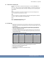
3.4.2 Packaging
The AKD packaging consists of recyclable cardboard with inserts and a label on the outside
of the box.
Model
up to AKD-x00606
Package
Dimensions
(mm) HxWxL
113 x 250 x 222
Total Weight
AKD-B, -P, -T
(kg)
1.7
Total Weight
AKD-M
(kg)
1.9
AKD-x01206
158 x 394 x 292
3.4
3.6
AKD-x02406
158 x 394 x 292
5
5.2
AKD-x00307 and AKD-x00607 158 x 394 x 292
4.3
4.5
AKD-x01207
158 x 394 x 292
4.3
4.5
AKD-x02407
158 x 394 x 292
6.7
6.9
3.4.3 Storage
Store the AKD in accordance with IEC 61800-2 as follows:
l
l
l
l
l
18
Store only in the manufacturer’s original recyclable packaging.
Store at or below maximum stacking height:
n AKD-x0306 to 0606 models: 8 cartons, all other models: 6 cartons
Store only within specified temperature ranges: -25 to +55 °C, max.rate of change 20
K/hour, class 1K4.
Storage only within specified humidity: 5 to 95% relative humidity, no condensation, class
1K3.
Store in accordance with the following duration requirements:
n Less than 1 year: without restriction.
n More than 1 year: capacitors must be re-formed before setting up and operating the
drive. To re-form the capacitors, remove all electrical connections and apply singlephase 120 VAC for about 30 minutes to the L1/L2 terminals.
Kollmorgen | September 2013
AKD Installation | 3 Safety
3.4.4 Maintenance and Cleaning
The drive does not require maintenance. Opening the drive voids the warranty.
The inside of the unit can only be cleaned by the manufacturer. To clean the drive exterior:
l
l
Casing: Clean with isopropanol or similar cleaning solution.
Protective grill on fan: Clean with a dry brush.
Do not immerse or spray the drive.
3.4.5 Uninstalling
If a drive must be uninstalled (such as for replacement), remove the drive as follows:
1. Switch off the main switch of the switchgear cabinet and the fuses that supply the system.
Wait at least seven minutes after disconnecting the drive from the main
supply power before touching potentially live sections of the equipment
(e.g. contacts) or undoing any connections. Always measure the voltage
in the DC bus link and wait until the voltage is below 40 V before touching or handling the drive.
2. Remove the connectors. Disconnect the potential earth connection last.
3. Check temperature.
During operation, the heat sink of the drive may reach temperatures
above 80 °C (176 °F). Before touching the device, check the temperature
and wait until it has cooled below 40 °C (104 °F).
4. Uninstall. Remove the drive and power supply from the conductive, grounded mounting
plate in the cabinet.
3.4.6 Repair and Disposal
Only the manufacturer can repair the drive. Opening the device voids the warranty. Uninstall
the drive as described in "Uninstalling" (➜ p. 19)), then send the drive in the original packaging to the manufacturer (see table below).
In accordance with the WEEE-2002/96/EC-Guidelines and similar, the manufacturer
accepts returns of old devices and accessories for professional disposal. Transport costs
are the responsibility of the sender. Send the devices to the manufacturer addresses shown
in the table below.
USA
Kollmorgen
201 West Rock Road
Radford, VA 24141
Europe
KOLLMORGEN Europe GmbH
Pempelfurtstr. 1
D-40880 Ratingen
Kollmorgen | September 2013
19
AKD Installation | 4 Approvals
4 Approvals
20
4.1 Conformance with UL/cUL
21
4.2 CE Conformance
22
4.3 Safe Torque Off (STO)
25
Kollmorgen | September 2013
AKD Installation | 4 Approvals
4.1 Conformance with UL/cUL
This drive is listed under UL (Underwriters Laboratories Inc.) file number E141084 Vol.3
Sec.5.
USL, CNL – Power conversion equipment (NMMS, NMMS7) – Models AKD followed by B,
P, S, T, M or F, followed by 003, 006, 012, and 024, followed by 06 or 07, followed by additional suffixes.
USL
Indicates Investigated to United States Standard for Power Conversion Equipment, UL
508C, Third Edition, Revised February 15, 2008.
CNL
Indicates investigation to Canadian Standard for Industrial Control Equipment, CAN/CSA C22.2 No. 14-2005, Second Edition, Revised April 2008.
Note:
CNL = Canadian National Standards - Listed.
USL = United States Standards - Listed.
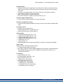
4.1.1 UL Markings
l
l
l
l
l
l
l
l
l
l
Identification of the terminals on the controller are coded so they may be identified in the
instructions. The instructions shall identify power connections for power supply, load, control, and ground.
Integral solid state short circuit protection does not provide branch circuit protection.
Branch circuit protection must be provided in accordance with the National Electrical
Code and any additional local codes.
This product is suitable for use on a circuit capable of delivering not more than 200,000
rms symmetrical amperes, 240 V (AKD-xzzz06) / 480 V (AKD-xzzz07) volts maximum,
when protected by fuses.
The following fuse types are recommended:
Model
Fuse class
Rating
Max. Fuse Rating
AKD-x00306
J
600 VAC, 200 kA
10 A
AKD-x00606
J
600 VAC, 200 kA
15 A
AKD-x01206
J
600 VAC, 200 kA
15 A
AKD-x02406
J
600 VAC, 200 kA
30 A
AKD-x00307
J
600 VAC, 200 kA
6A
AKD-x00607
J
600 VAC, 200 kA
10 A
AKD-x01207
J
600 VAC, 200 kA
15 A
AKD-x02407
J
600 VAC, 200 kA
30 A
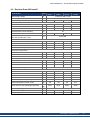
These drives provide solid state motor overload protection at 125% of the rated FLA Current.
These devices are intended to be used in a pollution degree 2 environment.
Maximum surrounding air temperature of 40°C.
Use minimum 75°C copper wire.
These devices do not provide over temperature sensing.
Use fuses only.
Kollmorgen | September 2013
21
AKD Installation | 4 Approvals
l
The following table illustrates the torque requirements for the field wiring connectors:
AKD-x00306
Mains Connector
5-7 in-lbs
5-7 in-lbs
24 VDC Input Connector
4 in-lbs
AKD-x00606
AKD-x01206
5-7 in-lbs
5-7 in-lbs
4 in-lbs
5-7 in-lbs
7 in-lbs
4 in-lbs
AKD-x02406
7 in-lbs
7 in-lbs
4 in-lbs
AKD-x00307
7 in-lbs
7 in-lbs
4 in-lbs
AKD-x00607
7 in-lbs
7 in-lbs
4 in-lbs
AKD-x01207
7 in-lbs
7 in-lbs
4 in-lbs
AKD-x02407
7 in-lbs
7 in-lbs
4 in-lbs
Model
Motor Phase Connector
4.2 CE Conformance
Conformance with the EC EMC Directive 2004/108/EC and the Low Voltage Directive
2006/95/EC is mandatory for the supply of drives within the European Community.
The drives have been tested by an authorized testing laboratory in a defined configuration,
using the system components that are described in this documentation. Any divergence from
the configuration and installation described in this documentation means that the user will be
responsible for carrying out new measurements to ensure conformance with regulatory
requirements.
AKD-xzzz06
AKD-xzzz06 drives do not have integrated EMC filters. These drives can cause highfrequency interferences and may require measures for interference suppression (such as
additional external EMC filters).
With external EMC filters for noise emission the AKD-xzzz06 meet the noise immunity
requirements of the second environmental category (industrial environment) to a product of
the category C2 (motor cable < 10 m).
With a motor cable length of 10 m or longer and external EMC filters, the AKD-xzzz06 meet
the requirement of category C3.
AKD-xzzz07
AKD-xzzz07 drives have integrated EMC filters.
The AKD-xzzz07 meet the noise immunity requirements to the 2nd environmental category
(industrial environment). For noise emission theAKD-xzzz07 meet the requirement to a product of the Category C2 (motor cable < 10 m).
With a motor cable length of 10 m or longer, the AKD-xzzz07 meet the requirement to the Category C3.
22
Kollmorgen | September 2013
AKD Installation | 4 Approvals
4.2.1 European Directives and Standards for the Machine Builder
Drives are components that are intended to be incorporated into electrical plant and
machines for industrial use. When the drives are built into machines or plant, the drive must
not be used until it has been established that the machine or equipment fulfills the requirements of the
l
l
l
EC Machinery Directive (2006/42/EC)
EC EMC Directive (2004/108/EC)
EC Low Voltage Directive (2006/95/EC)
Standards to be applied for conformance with the EC Machinery Directive (2006/42/EC)
l
l
IEC 60204-1 (Safety and Electrical Equipment in Machines)
ISO 12100 (Safety of Machines)
The manufacturer of the machine must generate a risk assessment for the
machine, and must implement appropriate measures to ensure that
unforeseen movements cannot cause injury or damage to any person or
property.
Standards to be applied for conformance with the EC Low Voltage Directive(2006/95/EC)
l
l
IEC 60204-1 (Safety and Electrical Equipment in Machines)
IEC 60439-1 (Low-voltage switchgear and controlgear assemblies)
Standards to be applied for conformance with the EC EMC Directive (2004/108/EC)
l
l
IEC 61000-6-1/2 (Interference Immunity in Residential & Industrial Areas)
IEC 61000-6-3/4 (Interference Generation in Residential & Industrial Areas)
The manufacturer of the machine/plant is responsible for ensuring that it meets the limits
required by the EMC regulations. Advice on the correct installation for EMC (such as shielding, grounding, treatment of connectors and cable layout) is shown in this manual.
The machine/plant manufacturer must check whether other standards or EC Directives must
be applied to the machine/plant.
Kollmorgen only guarantees the conformance of the servosystem with the standards cited in
this chapter if the components (motor, cables, chokes etc.) are those supplied by Kollmorgen.
Kollmorgen | September 2013
23
AKD Installation | 4 Approvals
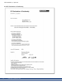
4.2.2 EC Declaration of Conformity
24
Kollmorgen | September 2013
AKD Installation | 4 Approvals
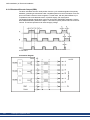
4.3 Safe Torque Off (STO)
An additional digital input (STO) releases the power output stage of the drive as long as a
24 V signal is applied to this input. If the STO input goes open-circuit, then power will no
longer be supplied to the motor, and the drive will lose all torque and coast to a stop.
The STO safety implementation on the AKD is certified by the IFA (Institut für Arbeitsschutz
der Deutschen Gesetzlichen Unfallversicherung). The safety circuit implementation for realizing the safety function "Safe Torque Off" in the drive is suited for SIL2 according to IEC
61508-2 and PLd, Cat.3 according to ISO 13849-1. The subsystems (AKD drives) are totally
described for safety technics with the characteristic data :
Device
STO
Operation
Mode
STO single
channel
ISO 13849-1
IEC 61508-2
PL d, CAT 3
SIL 2
PFH
[1/h]
0
TM [Years]
20
SFF
[%]
100
Kollmorgen | September 2013
25
AKD Installation | 5 Package
5 Package
26
5.1 Package Supplied
27
5.2 Nameplate
27
5.3 Part Number Scheme
28
Kollmorgen | September 2013
AKD Installation | 5 Package
5.1 Package Supplied
When a drive from the AKD series is ordered, the following items are included in the drive
package:
l
l
l
l
l
l
l
AKD
Printed copy of AKD Installation Manual (EU only)
Printed copy of AKD Quick Start (not in EU)
Printed copy of fault and warning card (not in EU)
DVD containing the setup software, WorkBench, and all product documentation in digital
format.
Mating connectors X1, X2, X3, X4 (if required), X7 and X8, X35 and X36 (if required)
Grounding plate, with AKD voltage type 07, with voltage type 06 for EU only
The mating SubD and RJ45 connectors are not included in the package.
Accessories Sold Separately
Accessories must be ordered separately if required; refer to your regional accessories manual:
l
l
l
l
l
l
l
l
EMC filters for 24 V and mains supply voltage, categories C2 or C3
External regen resistor
Motor cable. Assembled motor cables are available for all regions.
Feedback cable. Assembled feedback cables are available for all regions.
Motor choke, for motor cables longer than 25 m
CAN termination connector (with CAN drives only)
Service cable to the network
Power cable, control cables, and fieldbus cables (as cutoff lengths)
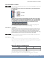
5.2 Nameplate
The nameplate depicted below is attached to the side of the drive, sample data entries are for
a 12 A type.
Kollmorgen | September 2013
27
AKD Installation | 5 Package
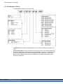
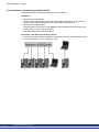
5.3 Part Number Scheme
The part number is identical to the order code.
Customization: this code includes language version of printed material and customer specials.
Connectivity Options: The drive models with connectivity option CC are fitted with both the
EtherCAT ( X5 and X6) and CANopen (X12 and X13) fieldbus connectors. A software parameter (DRV.TYPE) allows you to select what features the drive supports; you cannot use
EtherCAT and CANopen at the same time. PROFINET is possible with Position Indexer
drives only (P version).
28
Kollmorgen | September 2013
AKD Installation | 6 Technical description and data
6 Technical description and data
6.1 The AKD Family of Digital Drives
30
6.2 Ambient Conditions, Ventilation, and Mounting Position
32
6.3 Mechanical Data
32
6.4 Inputs/Outputs
33
6.5 Electrical Data AKD-xzzz06
34
6.6 Electrical Data AKD-xzzz07
35
6.7 Performance Data
36
6.8 Recommended Tightening Torques
36
6.9 Fusing
37
6.10 Grounding System
37
6.11 Connectors
38
6.12 Cable and Wire Requirements
39
6.13 Dynamic Braking
40
6.14 Switch-On and Switch-Off Behavior
43
6.15 Stop / Emergency Stop / Emergency Off
50
6.16 Safe Torque Off (STO)
52
6.17 Shock-hazard Protection
58
Kollmorgen | September 2013
29
AKD Installation | 6 Technical description and data
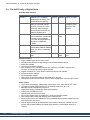
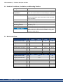
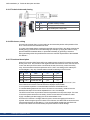
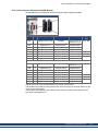
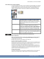
6.1 The AKD Family of Digital Drives
Available AKD versions
Variant (short) Description
Current Housing Connectivity
AKD-B***
Base drive is controlled by
3 to 24 A Standard Analog, SynqNet
analog torque & velocity commands (electronic gearing).
AKD-P**
Position Indexer drive adds the 3 to 24 A Standard Analog, CANopen,
ability to command multiple
EtherCAT, PROmotions, process I/O, make
FINET RT, Ethdecisions, add time delays,
ernet/IP
and modify drive process variables to the base drive.
AKD-M***-MC
Motion Controller PDMM/Ether- 3 to 24 A Extended EtherCAT
CAT master drive. Includes all
width
five IEC 61131 languages,
PLC Open and Pipes Network.
This drive is called AKD
PDMM.
AKD-T***
Simple BASIC pro3 to 24 A Standard Analog
grammability added to theBase
drive. This drive is called AKD
BASIC.
AKD-T***-IC
AKD BASIC with I/O expansion.
3 to 24 A Extended Analog, I/O expanwidth
sion
Standard features
l
l
l
l
l
l
l
l
l
l
Supply voltage range 120 V to 480 V ±10%
Several housing dimensions, depending on current and hardware options.
Motion bus onboard.
TCP/IP service channel onboard.
SFD, Hiperface DSL, Tamagawa Smart Abs, Resolver, Comcoder, 1Vp-p Sin-Cos
encoders, incremental encoders support onboard.
Support for ENDAT 2.1 & 2.2, BiSS or HIPERFACE protocols onboard.
Encoder emulation onboard.
Second feedback support.
Safe Torque Off (STO) according to IEC 61508 SIL 2 onboard.
Use with Synchronous servomotors, linear motors, and induction machines can be used.
Power section
l
l
l
l
l
l
l
l
l
l
30
One or three phase supply, voltage range 120 to 480 V ±10%, 50 to 400 Hz ±5% or DC.
Connection to higher voltage mains only via isolating transformer, ➜ p. 90
B6 bridge rectifier, integral soft-start circuit.
Single phase supply possible with output power derating.
Fusing to be provided by the user.
Shielding star point close to the drive.
DC bus link voltage range 170 to 680 VDC, can be connected in parallel.
Output stage IGBT module with floating current measurement.
Regen circuit with dynamic distribution of the generated power between several drives on
the same DC bus link circuit.
Internal regen resistor for all 240/480 VAC AKD-xzzz07 models (only 120/240 VAC 3 A
and 6 A AKD-xzzz06 models lack internal regen resistors), external regen resistors if
required.
Kollmorgen | September 2013
AKD Installation | 6 Technical description and data
Integrated safety
l
l
l
l
l
Appropriate insulation/creepage distances and electrical isolation for safe electrical separation, per IEC 61800-5-1, between the power input/motor connections and the signal
electronics.
Soft-start, overvoltage detection, short-circuit protection, phase-failure monitoring.
Temperature monitoring of the drive and motor.
Motor overload protection: foldback mechanism
SIL 2 safe torque off in accordance with IEC 61508, ➜ p. 52.
Auxiliary supply voltage 24V DC
l
From an external, safety approved 24 V ±10% power supply.
Operation and parameter setting
l
Using the setup software WorkBench for setup via TCP/IP or KAS IDE for AKD PDMM
setup.
Full digital control
l
l
l
Digital current controller (670 ns)
Adjustable digital velocity controller (62.5 µs)
Software option position controller (250 µs)
Inputs/Outputs
l
l
l
l
l
l
l
1 programmable analog input ➜ p. 128
1 programmable analog output ➜ p. 129
7 programmable digital inputs ➜ p. 130
2 programmable digital outputs ➜ p. 133
1 Enable input ➜ p. 130
1 STO input ➜ p. 52
additional digital inputs and outputs depending on variants (for example AKD PDMM)
Option Cards
Integrated option cards affect the device width.
l
l
IC: additional digital inputs and outputs.
MC: Motion Controller card with additional digital inputs and outputs. Extends the AKD to
AKD PDMM type (part number scheme: AKD-M), a master drive for multiaxis, synchronized drive systems.
Connectivity
l
l
l
l
l
Inputs/Outputs (➜ p. 124)
Encoder feedback output (➜ p. 122)
Service Interface (➜ p. 148)
CANopen (➜ p. 152), optional
Motion Bus interface (➜ p. 157)
n SynqNet (➜ p. 159), optional
n EtherCAT (➜ p. 158), optional
n PROFINET RT (➜ p. 159), optional
n Ethernet/IP (➜ p. 159), optional
Kollmorgen | September 2013
31
AKD Installation | 6 Technical description and data
6.2 Ambient Conditions, Ventilation, and Mounting Position
Storage
➜ p. 18
Transport
➜ p. 18
Ambient temperature
in operation
0 to +40 °C under rated conditions
+40 to +55 °C with continuous current derating 4 % per Kelvin
Humidity in operation
Relative humidity 5 to 85%, no condensation, class 3K3
Site altitude
Up to 1000 meters above mean sea level without restriction
1,000 to 2,500 meters above mean sea level with power derating 1.5%/100 m
Pollution level
Pollution level 2 as per IEC 60664-1
Vibrations
Class 3M1 according to IEC 60721-3-3
Enclosure protection
IP 20 according to IEC 60529
Mounting position
Vertical, ➜ p. 61
Ventilation
Built-in fan (except AKD-x00306 type)
The drive shuts down (fault F234, ➜ p. 178, motor has no
torque) in case of excessively high temperature in the control
cabinet. Make sure sufficient forced ventilation is supplied
within the control cabinet.
6.3 Mechanical Data
Mechanical data
Weight (standard width)
Weight (extended width)
AKD
-x00306
kg
AKD
-x00606
1.1
AKD
-x01206
2
AKD
-x02406
3.7
kg
1.3
2.2
4
Height, without connectors
mm
168
196
248
Height, with connector
mm
200
225
280
Standard Width front/back
mm
54/59
72/78.4
96/100
Extended Width front/back
mm
84/89
91/96
96/100
Depth, without connectors
mm
156
187
228
Depth, with connectors
mm
185
< 215
<265
AKD
-x01207
AKD
-x02407
5.3
Mechanical data
32
Units
Units
AKD
-x00307
AKD
-x00607
2.7
Weight (standard width)
kg
Weight (extended width)
kg
2.9
5.5
Height, without connectors
mm
256
306
Height, with connector
mm
290
340
Standard Width front/back
mm
65/70
99/105
Extended Width front/back
mm
95/100
99/105
Depth, without connectors
mm
185
228
Depth, with connectors
mm
<225
<265
Kollmorgen | September 2013
AKD Installation | 6 Technical description and data
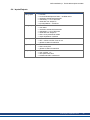
6.4 Inputs/Outputs
Interface
Analog inputs
Analog outputs
Electrical Data
l ±12 VDC
l Common Mode Rejection Ratio: > 30 dB at 60 Hz
l resolution 16 bit and full monotonic
l nonlinearity < 0.1% of full scale
l offset drift max. 250µV/°C
l input impedance > 13 kOhms
l
l
l
l
l
l
l
Digital inputs
l
l
l
Digital outputs
l
l
l
Relay outputs
l
l
l
l
±10 VDC
max 20mA
resolution 16 bit and full monotonic
nonlinearity < 0.1% of full scale
offset drift max. 250µV/°C
short circuit protected to AGND
output impedance 110 Ohms
ON: 3.5 VDC to 30 VDC, 2 mA to 15 mA
OFF: -2 VDC to 2 VDC, max.15 mA
galvanic isolation for 250 VDC
max. 30 VDC, 100 mA
short circuit proof
galvanic isolation for 250 VDC
max. 30 VDC, 1A
max. 42 VAC, 1 A
time open/close 10ms
isolation 400 VDC contact/coil
Kollmorgen | September 2013
33
AKD Installation | 6 Technical description and data
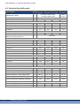
6.5 Electrical Data AKD-xzzz06
Electrical Data
Rated supply voltage
Rated supply input frequency
Rated input power for S1 operation
Units
V
AKDAKDAKDx00306
x00606
x01206
3 x 120 V to 240 V ±10%
1 x 120 V to 240 V ±10%
Hz
AKDx02406
3x240 V
±10%
50 Hz to 400 Hz ±5% or DC
kVA
1.2
2.38
3.82
7.6
at 1x120 V
A
5.0
9.9
12
N/A
at 1x240 V
A
5.0
9.9
12
N/A
at 3x120 V
A
2.3
4.6
9.2
N/A
at 3x240 V
A
2.3
4.6
9.2
18.3
10
20
Rated input current
Permitted switch on/off frequency
1/h
Max. inrush current
A
Rated DC bus link voltage
(Bus Turn on Delay 3ph 1 sec)
V
30
10
10
170 to 340
Continuous output current ( ± 3%)
at 120 V
Arms
3
6
12
N/A
at 240 V
Arms
3
6
12
24
Peak output current (for 5 s, ± 3%)
Arms
9
18
30
48
at 1x120 V
W
312.5
625
1250
N/A
at 1x240 V
W
625
1250
2500
N/A
at 3x120 V
W
312.5
625
1250
N/A
at 3x240 V
W
625
1250
2500
5000
at 1x120 V
kVA
0.937
1.875
3.125
N/A
at 1x240 V
kVA
1.875
3.750
6.250
N/A
at 3x120 V
kVA
0.937
1.875
3.125
N/A
at 3x240 V
kVA
1.875
3.750
6.250
10
Continuous output power
Peak output power (for 1 s)
Technical data for regen circuit
➜ p. 40
—
Motor inductance min.
34
at 120 V
mH
1.3
0.6
0.5
0.3
at 240 V
mH
2.5
1.3
1
0.6
Motor inductance max.
mH
250
125
100
60
Thermal dissipation, output stage disable
W
max. 20
max. 20
max. 20
max. 25
Thermal dissipation at rated current
W
31
57
137
175
Noise emission (low speed/high speed fan)
dB
(A)
N/A
33/39
37/43
41/56
Aux. voltage supply
V
-current B, P, T types without/with motor brake
A
0.5 / 1.7
0.6 / 1.8
0.7 / 1.9
1.0 / 2.5
-current M type without/with motor brake
A
0.8 / 2.0
0.9 / 2.1
1.0 / 2.2
1.3 / 2.8
Kollmorgen | September 2013
24 V (±10%, check voltage drop)
AKD Installation | 6 Technical description and data
6.6 Electrical Data AKD-xzzz07
Electrical data
Rated supply voltage
Rated supply input frequency
Rated input power for S1 operation
V
AKDAKDx00607
x01207
3 x 240 V to 480 V ±10%
Hz
AC with 50 Hz to 400 Hz ±5% or DC
Units
AKDx00307
AKDx02407
kVA
2.24
4.49
7.65
15.2
at 3x240 V
A
2.7
5.4
9.2
18.3
at 3x400 V
A
2.7
5.4
9.2
18.3
at 3x480 V
A
2.7
5.4
9.2
18.3
10
20
Rated input current
Permitted switch on/off frequency
Max. inrush current
Rated DC bus link voltage
(Bus Turn on Delay 3ph 1 sec)
1/h
A
30
10
10
V=
340 to 680
Continuous output current ( ± 3%)
at 240 V
Arms
3
6
12
24
at 400 V
Arms
3
6
12
24
at 480 V
Arms
3
6
12
24
Peak output current (for 5 s, ± 3%)
Arms
9
18
30
48
at 3x240 V
kVA
0.6
1.25
2.5
5
at 3x400 V
kVA
1
2
4.2
8.3
at 3x480 V
kVA
1.2
2.5
5
10
at 3x240 V
kVA
1.8
3.75
6.25
10
at 3x400 V
kVA
3
6.75
10.4
16.7
at 3x480 V
kVA
3.6
7.5
12.5
20
Continuous output power
Peak output power (for 1 s)
Technical data for regen circuit
➜ p. 40
—
Motor inductance min.
at 240 V
mH
3.2
1.6
1.3
0.6
at 400 V
mH
5.3
2.6
2.1
1
at 480 V
mH
6.3
3.2
2.5
1.2
Motor inductance max.
mH
600
300
250
120
Thermal dissipation, output stage disable
W
max. 20
max. 20
max. 20
max. 25
Thermal dissipation at rated current
W
102
129
153
237
Noise emission (low speed/high speed fan)
dB
(A)
34/43
34/43
44/52
48/58
Aux. voltage supply
V=
-current B, P, T types without/with motor brake A=
-current M type without/with motor brake
A=
24 V (±10%, check voltage drop)
1 / 2.5
1 / 2.5
1 / 2.5
2/4
1.3 / 2.8
1.3 / 2.8
1.3 / 2.8
2.3 / 4.3
Kollmorgen | September 2013
35
AKD Installation | 6 Technical description and data
6.7 Performance Data
AKD-xzzz06
Performance Data
Units
Switching frequency of output stage
Voltage rise speed dU/dt
up to AKDx00606
10
kHz
kV/µs
AKDx01206
8
AKDx02406
8
2.5
Bandwidth of current controller
kHz
2.5 to 4
Bandwidth of velocity controller (scalable)
Hz
0 to 1000
Bandwidth of position controller (scalable)
Hz
4.3
2 to 3
0 to 800
0 to 600
1 to 250
AKD-xzzz07
Performance Data
Units
Switching frequency of output stage
Voltage rise speed dU/dt
kHz
AKDx00307
8
AKDAKDx00607 x01207
8
6
kV/µs
Bandwidth of current controller
kHz
Bandwidth of velocity controller (scalable)
Hz
Bandwidth of position controller (scalable)
Hz
AKDx02407
8
7.2
2.5 to 4
0 to 800
2 to 3
0 to 600
1 to 250
6.8 Recommended Tightening Torques
Connector
X1
Tightening Torque/Nm
up to AKD-x00606 AKD-x01206 AKD-x02406 and AKD-xzzz07
0.22 to 0.25
0.22 to 0.25
0.22 to 0.25
X2
0.5 to 0.6
0.7 to 0.8
0.7 to 0.8
X3
0.5 to 0.6
0.5 to 0.6
0.7 to 0.8
X4
-
-
0.7 to 0.8
X7, X8, X21, X22,
X23, X24, X35, X36
0.2 to 0.25
0.2 to 0.25
0.2 to 0.25
PE block
1.7
1.7
1.7
See "Conformance with UL/cUL" (➜ p. 21) for in-lbs values.
36
Kollmorgen | September 2013
AKD Installation | 6 Technical description and data
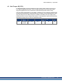
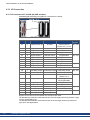
6.9 Fusing
US fuses: Class J, 600 VAC 200 kA, time-delay. The fuse must be UL and CSA listed, UL
recognized is not sufficient.
EU fuses: types gRL or gL, 400 V/500 V, time-delay
Fuse holders: Combined with the standard fuse blocks, finger safe fuse holders must be
used according to IEC 60529.
Examples:
Bussmann: CH Series Modular Fuse Holders, fuse size 0 to 30A class J, 3 poles: CH30J3
Ferraz: Ultrasafe Fuse holders, fuse size 0 to 30A class J, 3 poles: US3J3I
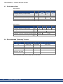
6.9.1 External power supply fusing
Drive
Model
Max.
Ampere rating
Example class J
Cooper Bussmann
Example class J
Ferraz Shawmut
AKD-x00306
10A (Time-Delay)
LPJ10SP/DFJ10
AJT10/HSJ10
AKD-x00606
15A (Time-Delay)
LPJ15SP/DFJ15
AJT15/HSJ15
AKD-x01206
15A (Time-Delay)
LPJ15SP/DFJ15
AJT15/HSJ15
AKD-x02406
30A (Time-Delay)
LPJ30SP/DFJ30
AJT30/HSJ30
AKD-x00307
6A (Time-Delay)
LPJ6SP/DFJ6
AJT6/HSJ6
AKD-x00607
10A (Time-Delay)
LPJ10SP/DFJ10
AJT10/HSJ10
AKD-x01207
15A (Time-Delay)
LPJ15SP/DFJ15
AJT15/HSJ15
AKD-x02407
30A (Time-Delay)
LPJ30SP/DFJ30
AJT30/HSJ30
6.9.2 External 24 V supply fusing
Drive
Model
Max.
Ampere rating
Example class J
Cooper Bussmann
Example class J
Ferraz Shawmut
all AKD
8A (Time-Delay)
LPJ8SP/DFJ8
AJT8
6.9.3 External regen resistor fusing
Drive Model
AKD-x003 to -x012
AKD-x024
Ampere UL region
rating
10A
example:
Cooper Bussmann
15A
type FWP-xxA14F
CE Region
example: Siba
110V to 400V: gRL(gS)
400V to 480V: aR
6.10 Grounding System
There are several ground networks in the drive:
AGND
analog ground
DCOM7, DCOM8
common line for digital inputs on I/O connector X7, X8
DCOM21, DCOM22 common line for digital inputs on I/O connector X21, X22 (I/O option
card only)
DCOM35, DCOM36 common line for digital inputs on I/O connector X35, X36(AKD-M
only)
GND
24 V supply, STO input, holding brake
0V
internal digital ground, encoder emulation output, service channel
Kollmorgen | September 2013
37
AKD Installation | 6 Technical description and data
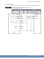
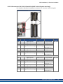
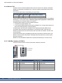
6.11 Connectors
Given voltage and current data are the lowest values allowed by UL and CE. AKD-xzzz06 Types (120V to 240V Mains Voltage Supply)
Connector
Control signals X7/X8
Type
Max. Cross
Cur- VoltSection1
rent2 age3
Terminal Connector, 10 poles 1.5 mm², 16 awg 10 A 250 V
Control signals X21/X22* Terminal Connector, 8 poles
1.5 mm², 16 awg 10 A
250 V
Control signals X23/X24* Terminal Connector, 14 poles 1.5 mm², 16 awg 10 A
250 V
Control signals X35/X36** Terminal Connector, 8 poles
1.5 mm², 16 awg 10 A
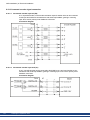
250 V
Aux. voltage X1
Terminal Connector, 3 poles
1.5 mm², 16 awg
8A
160 V
Motor X2 (3 to 6 A)
Terminal Connector, 6 poles
2.5 mm², 14 awg 10 A
300 V
Motor X2 (12 to 24 A)
Terminal Connector, 6 poles
10 mm², 8 awg
30 A
600 V
Power X3 (3 to 6A)
Terminal Connector, 7 poles
2.5 mm², 14 awg 10 A
300 V
Power X3 (12 A)
Terminal Connector, 8 poles
2,5 mm², 14 awg 16 A
300 V
Power X3 (24 A)
Terminal Connector, 4 poles
10 mm², 8 awg
30 A
600 V
Power X4 (24 A)
Terminal Connector, 4 poles
10 mm², 8 awg
30 A
600 V
Feedback X10
SubD 15pin HD (female)
0,5 mm², 21 awg
1A
<100 V
Service Port X11, X32*
RJ45
0,5 mm², 21 awg
1A
<100 V
Motion Bus X5, X6
RJ45
0,5 mm², 21 awg
1A
<100 V
CAN In/Out X12/13
RJ25
0,5 mm², 21 awg
1A
<100 V
Encoder Emulation X9
SubD 9pin (male)
0,5 mm², 21 awg
1A
<100 V
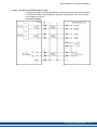
AKD-xzzz07 Types (240V to 480V Mains Voltage Supply)
Connector
Control signals X7/X8
Type
Max. Cross
Cur- VoltSection1
rent2 age3
Terminal Connector, 10 poles 1.5 mm², 16 awg 10 A 250 V
Control signals X21/X22* Terminal Connector, 8 poles
1.5 mm², 16 awg 10 A
250 V
Control signals X23/X24* Terminal Connector, 14 poles 1.5 mm², 16 awg 10 A
250 V
Control signals X35/X36** Terminal Connector, 8 poles
1.5 mm², 16 awg 10 A
250 V
Aux. voltage X1
Terminal Connector, 3 poles
1.5 mm², 16 awg
8A
160 V
Motor X2
Terminal Connector, 6 poles
10 mm², 8 awg
30 A
600 V
Power X3, X4
Terminal Connector, 4 poles
10 mm², 8 awg
30 A
600 V
Feedback X10
SubD 15pin HD (female)
0,5 mm², 21 awg
1A
<100 V
Service Port X11, X32*
RJ45
0,5 mm², 21 awg
1A
<100 V
Motion Bus X5, X6
RJ45
0,5 mm², 21 awg
1A
<100 V
CAN In/Out X12/13
RJ25
0,5 mm², 21 awg
1A
<100 V
Encoder Emulation X9
SubD 9pin (male)
0,5 mm², 21 awg
1A
<100 V
1single-line connection
2single-line connection with recommended conductor cross section (➜ p. 39)
3rated voltage with pollution level 2
* with I/O option card "IC" only
** with AKD-M variant only
38
Kollmorgen | September 2013
AKD Installation | 6 Technical description and data
6.12 Cable and Wire Requirements
6.12.1 General
For information on the chemical, mechanical, and electrical characteristics of the cables
please refer to the accessories manual or contact customer support.
To reach the maximum permitted cable length, you must use cable material with the following capacitance (phase to shield) requirements:
l
l
Motor cable: less than 150 pF/m
Resolver/Encoder cable: less than 120 pF/m
Motor cables longer than 25 m may require the use of a motor choke.
6.12.2 Cable cross sections and requirements
The table below describes the recommended interface cross sections and cable requirements for single-axis systems in accordance with IEC 60204. For multi-axis systems,
observe the specific operating conditions for your system.
Interface
AC connection
Cross Section
up to AKD-x006: 1.5 mm² (16 awg)
AKD-x012: 2.5 mm² (14 awg)
AKD-x024: 4 mm² (12 awg)
Cable Requirements
600 V,minimum 75°C
DC bus link,
regen resistor
up to AKD-x006: 1.5 mm² (16 awg)
AKD-x012 to 24: 2.5 mm² (14 awg)
1000 V, minimum 75°C,
shielded
for lengths >0.20 m
Motor cables without
choke, max. 25 m
up to AKD-x006: 1.5 mm² (16 awg)
AKD-x012: 2.5 mm² (14 awg)
AKD-x024: 4 mm² (12 awg)
600 V,minimum 75°C,
shielded,
capacitance <150 pF/m
Motor cables with choke,
25 - 50 m
up to AKD-x006: 1.5 mm² (16 awg)
AKD-x012: 2.5 mm² (14 awg)
AKD-x024: 4 mm² (12 awg)
600 V,minimum 75°C,
shielded,
capacitance <150 pF/m
Resolver, max.100 m
4x2x0.25 mm² (24 awg)
twisted pairs, shielded,
capacitance <120 pF/m
SFD, max. 50 m
1x2x0.25 mm² (24 awg)
twisted pairs, shielded
1x2x0.50 mm² (21 awg)
Encoder, max. 50 m
7x2x0.25 mm² (24 awg)
twisted pairs, shielded
ComCoder, max. 25 m
8x2x0.25 mm² (24 awg)
twisted pairs, shielded
Analog I/Os, max. 30 m
0.25 mm² (24 awg)
twisted pairs, shielded
Digital I/Os, max. 30 m
0.5 mm² (21 awg)
single line
Holding brake (motor)
min. 0.75 mm² (19 awg)
600 V,minimum 75°C,
shielded
+24 V / GND, max 30 m
max. 2.5 mm² (14 awg)
single line
Kollmorgen | September 2013
39
AKD Installation | 6 Technical description and data
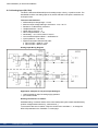
6.13 Dynamic Braking
Dynamic braking is a method to slow down a servo system by dissipating the mechanical
energy driven by the motor back EMF. The AKD has a built in advanced dynamic braking
mode which operates fully in hardware. When activated, the drive shorts the motor terminals
in phase with the back EMF (q axis) but continues to operate the non-force producing current
loop (d-axis) with 0 current. This forces all of the dynamic braking current to be stopping current and insures the fastest stopping/amp of motor terminal current.
l
l
l
When current is not being limited, the mechanical energy is being dissipated in the motor
resistance.
When current is being limited, energy is returned to the drive bus capacitors.
The drive also limits the maximum dynamic braking motor terminal current via the
DRV.DBILIMIT parameter to insure that the drive, motor, and customer load do not see
excessive currents/forces.
Whether and how the AKD uses dynamic braking depends on (DRV.DISMODE).
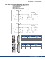
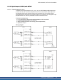
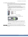
6.13.1 Regen circuit
When the amount of returned energy builds the bus capacitor voltage up enough the drive activates the regen circuit to start dumping the returned energy in the regen resistor (also called
regenerative or brake resistor). This resistor could be internal or connected external to the
drive, depending on drive model and drive wiring.
AKD-x00306 to AKD-x00606
No internal regen resistor. Depending on the application requirements, an external resistor
can be connected.
AKD-x01206 to AKD-x02406 and AKD-xzzz07
With internal resistor plus the ability to connect an external resistor depending on the application requirements.
External regen resistors are described in the regional AKD Accessories Manual.
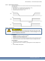
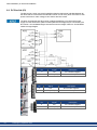
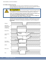
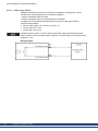
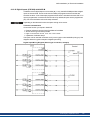
6.13.1.1 Functional description
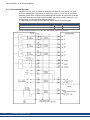
When the amount of returned energy builds the bus capacitor voltage up enough the drive activates the brake chopper to start dumping the returned energy in the regen resistor.
1. Individual drives, not coupled through the DC bus link circuit (+DC, -DC)
When the energy fed back from the motor has an average or peak power that exceeds the preset level for the regen power rating, the drive generates the warning "n521 Regen Over
power”. If the power increases past the fault level, the regen circuit will switch off.
With the regen circuit switched off, the drive internal DC bus link voltage is supervised. The
drive reports an over-voltage fault if the DC bus threshold is exceeded. The drive power
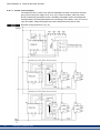
stage is disabled and the load coasts to a stop with the fault message “F501 Bus Over voltage" (➜ p. 178). The Fault contact (terminals X8/9-10) is opened (➜ p. 134) due to this fault.
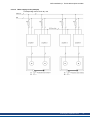
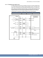
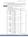
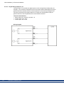
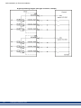
2. Several drives coupled through the DC bus link (+DC, -DC)
Using the built-in regen circuit, several drives of the same series can be operated from a common DC-bus link (➜ p. 94), without any additional measures. 90% of the combined power of
all the coupled drives is always available for peak and continuous power. The switch-off on
over voltage takes place as described under 1. (above) for the drive that has the lowest
switch-off threshold (resulting from tolerances).
40
Kollmorgen | September 2013
AKD Installation | 6 Technical description and data
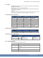
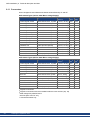
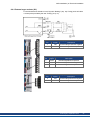
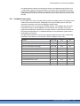
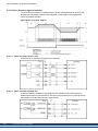
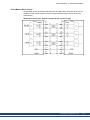
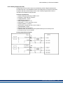
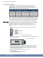
6.13.1.2 Technical data for AKD-xzzz06
Technical data for the regen circuit depends on the drive type and the mains voltage.
Supply voltages, capacitances, and switch-on voltages are all nominal values.
Observe the regeneration time (some minutes) for the dynamic brake circuit after full load
with peak regen power.
Brake circuit
Supply
voltage
Units 120 V / 240 V
V
380
Type
Rated data
AKD-xzzz06 Switch-on threshold of regen circuit
all types
Overvoltage limit
Maximum regen duty cycle
Type
Rated data
AKD-x00106 External regen resistor
V
420
%
15*
Units 120 V / 240 V
Ohm
33
Maximum continuous regen power, external resistor
kW
0.48
Peak regen power, external (1s)
kW
5.4
Absorption energy in capacitors (+/- 20%)
Ws
60 / 20
DC Bus Capacitance
µF
940
Ohm
33
Maximum continuous regen power, external resistor
kW
0.77
Peak regen power, external (1s)
kW
5.4
Absorption energy in capacitors (+/- 20%)
Ws
60 / 20
DC Bus Capacitance
µF
940
Ohm
33
Maximum continuous regen power, external resistor
kW
1.5
Peak regen power, external resistor (1s)
kW
5.4
Absorption energy in capacitors (+/- 20%)
Ws
60 / 20
DC Bus Capacitance
µF
940
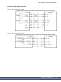
AKD-x00306 External regen resistor
AKD-x00606 External regen resistor
AKD-x01206 Internal regen resistor
Ohm
15
Continuous power, internal resistor
W
100
Peak regen power, internal resistor (0.5s)
kW
11.7
Ohm
33
External regen resistor
Maximum continuous regen power, external resistor
kW
3
Absorption regen power, external resistor (1s)
kW
5.4
Storeable energy in capacitors (+/- 20%)
Ws
160 / 55
DC Bus Capacitance
µF
2460
AKD-x02406 Internal regen resistor
Ohm
8
Continuous power, internal resistor
W
200
Peak regen power, internal resistor (0.5s)
kW
22
Ohm
15
External regen resistor
Maximum continuous regen power, external resistor
kW
6
Peak regen power, external resistor (1s)
kW
11.8
Absorption energy in capacitors (+/- 20%)
Ws
180 / 60
DC Bus Capacitance
µF
2720
* depends on connected regen resistor power
Kollmorgen | September 2013
41
AKD Installation | 6 Technical description and data
6.13.1.3 Technical data for AKD-xzzz07
Technical data for the regen circuit depends on the drive type and the mains voltage.
Supply voltages, capacitances, and switch-on voltages are all nominal values.
Observe the regeneration time (some minutes) after full load with peak regen power.
Brake circuit
Type
Rated data
AKDSwitch-on threshold of regen circuit
xzzz07
Overvoltage limit
all types
Maximum regen duty cycle
Type
AKDx00307
Rated data
Internal regen resistor
W
840
15*
240 V
400 V / 480 V
33
80
5.5
Ohm
22.1
33
Maximum continuous regen power, external
resistor
kW
0.77
1.5
Peak regen power, external (1s)
kW
5,4
21.4
Absorption energy in capacitors (+/- 20%)
Ws
5
DC Bus Capacitance
µF
235
Internal regen resistor
Ohm
33
W
100
Continuous power, internal resistor
kW
35 / 20
5.4
Ohm
21.4
33
Maximum continuous regen power, external
resistor
kW
1.5
3
Peak regen power, external resistor (1s)
kW
5.4
21.4
Absorption energy in capacitors (+/- 20%)
Ws
5
35 / 20
DC Bus Capacitance
µF
235
Internal regen resistor
Ohm
33
Continuous power, internal resistor
W
100
Peak regen power, internal resistor (0.5s)
kW
External regen resistor
5.4
Ohm
21.4
33
Maximum continuous regen power, external
resistor
kW
3
6
Peak regen power, external resistor (1s)
kW
5.4
21.4
Absorption energy in capacitors (+/- 20%)
Ws
10
70 / 40
DC Bus Capacitance
µF
Internal regen resistor
470
Ohm
23
Continuous power, internal resistor
W
200
Peak regen power, internal resistor (0.5s)
kW
External regen resistor
7.7
Ohm
30.6
23
Maximum continuous regen power, external
resistor
kW
6
12
Peak regen power, external resistor (1s)
kW
7.7
30.6
Absorption energy in capacitors (+/- 20%)
Ws
15
110 / 60
DC Bus Capacitance
µF
* depends on connected regen resistor power
42
Units
Ohm
kW
External regen resistor
AKDx02407
420
%
Peak regen power, internal resistor (0.5s)
Peak regen power, internal resistor (0.5s)
AKDx01207
V
Continuous power, internal resistor
External regen resistor
AKDx00607
Units
V
Supply voltage
240 V 400 V / 480 V
380
760
Kollmorgen | September 2013
680
AKD Installation | 6 Technical description and data
6.14 Switch-On and Switch-Off Behavior
This chapter describes the switch-on and switch-off behavior of the AKD.
Behavior of “holding brake” function
Drives with an enabled holding brake function have a special timing for switching on and off
the output stage (➜ p. 102). Events that remove the DRV.ACTIVE signal trigger the holding
brake to apply. As with all electronic circuits, the general rule applies that there is a possibility of the internal holding brake module failing.
Functional safety, e.g. with hanging load (vertical axes), requires an additional mechanical
brake which must be safely operated, for example by a safety control.
If velocity drops below threshold CS.VTHRESH or timeout occurs during a stop procedure,
the brake is applied. Set parameter MOTOR.BRAKEIMM to 1 with vertical axes, to apply the
motor holding brake (➜ p. 102) immediately after faults or Hardware Disable.
Behavior when undervoltage condition is present
The behavior in an undervoltage condition depends on the VBUS.UVMODE setting.
VBUS.UVMODE DC Bus Undervoltage Mode. Consult the AKD User Guide for configuring the parameter.
0
The drive will report a F502 undervoltage fault any time an undervoltage
condition occurs.
1 (default)
The drive will report a warning n502 if not enabled. The drive will report a
fault if the drive is enabled when the condition occurs, or an attempt is
made to enable while an under voltage condition occurs.
Safety function STO
With the personnel safe function STO, the drive can be secured on standstill using its internal electronics so that even when power is being supplied, the drive shaft is protected
against unintentional restart. The chapter “Safe Torque Off (STO)” describes how to use the
STO function (➜ p. 52).
Kollmorgen | September 2013
43
AKD Installation | 6 Technical description and data
6.14.1 Switch-on behavior in standard operation
The diagram below illustrates the correct functional sequence for switching the drive on.
Fault F602 occurs when STO (➜ p. 52) does not have current when HW enable becomes
active.
44
Kollmorgen | September 2013
AKD Installation | 6 Technical description and data
6.14.2 Switch-off behavior
The drive’s 24 V supply must remain constant. Hardware Enable input disables the power
stage immediately. Configured Digital Inputs and fieldbus commands can be used to perform controlled stops.
6.14.2.1 Switch-off behavior using the DRV.DIS command
The enable/disable button in WorkBench issues a drv.dis command internally to the drive.
See AKD User Guide for configuring inputs and software commands. Sometimes this enable
signal is called "Software Enable" (SW-Enable).
DRV.DISMODE DRV.DISMODE controls the behavior of the drv.dis command issued
through WorkBench, or terminal, or fieldbus. Consult the AKD User
Guide for configuring.
0
Disable axis immediately, if velocity drops below threshold
CS.VTHRESH or timeout occurs brake is applied. Category 0 stop
according to IEC 60204(➜ p. 50).
2
Use controlled stop to disable drive, if velocity drops below threshold
CS.VTHRESH or timeout occurs brake is applied. Category 1 stop
according to IEC 60204(➜ p. 50).
If velocity drops below threshold CS.VTHRESH or timeout occurs brake is applied
(➜ p. 102).
Kollmorgen | September 2013
45
AKD Installation | 6 Technical description and data
6.14.2.2 Switch-off behavior using a digital input (controlled stop)
This is a category 2 stop according to IEC 60204 (➜ p. 50).
A digital input can be configured to bring the motor to a controlled stop and then disable the
drive and apply the holding brake.(if present). See the AKD User Guide for information on configuring Digital Inputs.
If velocity drops below threshold CS.VTHRESH or timeout occurs brake is applied
(➜ p. 102).
6.14.2.3 Switch-off behavior using HW Enable input (uncontrolled stop)
This is a category 0 stop according to IEC 60204 (➜ p. 50).
The hardware enable input disables the power stage immediately.
If velocity drops below threshold CS.VTHRESH or timeout occurs the motor holding brake is
applied (➜ p. 102). Set parameter MOTOR.BRAKEIMM to 1 with vertical axes, to apply the
motor holding brake immediately after Hardware Disable.
46
Kollmorgen | September 2013
AKD Installation | 6 Technical description and data
6.14.2.4 Switch-off behavior in the event of a fault
The behavior of the drive always depends on the fault type and the setting of a number of different parameters (DRV.DISMODE, VBUS.UVFTHRESH, CS.VTHRESH, and others; see
the AKD User Guide or WorkBench help for more details).See the Drive Fault and Warning
Messages and Remedies section of the AKD User Guide for a table describing the specific
behavior of each fault.
The follwing pages show examples for the possible fault behaviors.
Switch-off behavior for faults that cause an immediate power stage disable
This is a category 0 stop according to IEC 60204 (➜ p. 50).
If velocity drops below threshold CS.VTHRESH or timeout occurs the motor holding brake is
applied (➜ p. 102). Set parameter MOTOR.BRAKEIMM to 1 with vertical axes, to apply the
motor holding brake immediately after faults.
Kollmorgen | September 2013
47
AKD Installation | 6 Technical description and data
Switch-off behavior for faults that cause dynamic braking
This is a category 0 stop according to IEC 60204 (➜ p. 50).
If velocity drops below threshold CS.VTHRESH or timeout occurs brake is applied
(➜ p. 102).
48
Kollmorgen | September 2013
AKD Installation | 6 Technical description and data
Switch-off behavior for faults that cause a controlled stop
This is a category 1 stop according to IEC 60204 (➜ p. 50).
If velocity drops below threshold CS.VTHRESH or timeout occurs brake is applied
(➜ p. 102).
Kollmorgen | September 2013
49
AKD Installation | 6 Technical description and data
6.15 Stop / Emergency Stop / Emergency Off
The control functions Stop, Emergency Stop and Emergency Off are defined by IEC 60204.
Notes for safety aspects of these functions can be found in ISO 13849 and IEC 62061.
The parameter DRV.DISMODE must be set to 2 to implement the different stop categories.
Consult the AKD User Guide for configuring the parameter.
Functional safety, e.g. with hanging load (vertical axes), requires an additional mechanical brake which must be safely operated, for example by a
safety control.
Set parameter MOTOR.BRAKEIMM to 1 with vertical axes, to apply the
motor holding brake (➜ p. 102) immediately after faults or Hardware Disable.
6.15.1 Stop
The stop function shuts down the machine in normal operation. The stop function is defined
by IEC 60204.
The Stop Category must be determined by a risk evaluation of the machine.
Stop function must have priority over assigned start functions. The following stop categories
are defined:
Stop Category 0
Shut-down by immediate switching-off the energy supply to the drive machinery (this is an
uncontrolled shut-down). With the approved safety function STO (➜ p. 52) the drive can be
stopped using its internal electronics (IEC 61508 SIL2).
Stop Category 1
A controlled shut-down, whereby the energy supply to the drive machinery is maintained to
perform the shut-down, and the energy supply is only interrupted when the shut-down has
been completed.
Stop Category 2
A controlled shut-down, whereby the energy supply to the drive machinery is maintained.
Stop Category 0 and Stop Category 1 stops must be operable independently of the operating
mode, whereby a Category 0 stop must have priority.
If necessary, provision must be made for the connection of protective devices and lock-outs.
If applicable, the stop function must signal its status to the control logic. A reset of the stop
function must not create a hazardous situation.
50
Kollmorgen | September 2013
AKD Installation | 6 Technical description and data
6.15.2 Emergency Stop
The Emergency Stop function is used for the fastest possible shutdown of the machine in a
dangerous situation. The Emergency Stop function is defined by IEC 60204. Principles of
emergency stop devices and functional aspects are defined in ISO 13850.
The Emergency Stop function will be triggered by the manual actions of a single person. It
must be fully functional and available at all times. The user must understand instantly how to
operate this mechanism (without consulting references or instructions).
The Stop Category for the Emergency Stop must be determined by a risk evaluation of the
machine.
In addition to the requirements for stop, the Emergency Stop must fulfil the following requirements:
l
l
l
Emergency Stop must have priority over all other functions and controls in all operating
modes.
The energy supply to any drive machinery that could cause dangerous situations must be
switched off as fast as possible, without causing any further hazards ( Stop Category 0)
or must be controlled in such a way, that any movement that causes danger, is stopped
as fast as possible (Stop Category 1).
The reset must not initiate a restart.
6.15.3 Emergency Off
The Emergency Off function is used to switch-off the electrical power supply of the machine.
This is done to prevent users from any risk from electrical energy (for example electrical
impact). Functional aspects for Emergency Off are defined in IEC 60364-5-53.
The Emergency Off function will be triggered by the manual actions of a single person.
The result of a risk evaluation of the machine determines the necessity for an Emergency Off
function.
Emergency Off is done by switching off the supply energy by electro-mechanical switching
devices. This results in a category 0 stop. If this stop category is not possible in the application, then the Emergency Off function must be replaced by other measures (for example
by protection against direct touching).
Kollmorgen | September 2013
51
AKD Installation | 6 Technical description and data
6.16 Safe Torque Off (STO)
An additional digital input (STO) releases the power output stage of the drive as long as a 24
V signal is applied to this input. If the STO input goes open-circuit, then power will no longer
be supplied to the motor, and the drive will lose all torque and coast to a stop.
Input STO (X1/3)
l
l
Floating, reference ground is GND
24 V ±10%, 20 mA
This input is not compatible with IEC 61131-2.
You can thus achieve a category 0 stop (➜ p. 50) by using the STO input without switching a
mains contactor.
Advantages of the STO function:
l
l
l
The DC bus link remains charged, since the mains supply line remains active.
Only low voltages are switched, so there is no contact wear.
Very little wiring is required.
The STO safety implemenation on the AKD is certified. The safety circuit implementation
used for the safety function "Safe Torque Off" in the drive is suited for SIL 2 according to IEC
61508-2 and PLd / CAT3 according to ISO 13849-1.
6.16.1 Safety characteristic data
The subsystems (AKD) are described with the following characteristic data:
Device
STO
Operation
Mode
STO single
channel
ISO 13849-1
IEC 61508-2
PL d, CAT 3
SIL 2
PFH
[1/h]
0
TM [Years]
20
SFF
[%]
100
6.16.2 Use as directed
The STO function is exclusively intended to provide a functional safe stop of the motion system. To achieve this functional safety, the wiring of the safety circuits must meet the safety
requirements of IEC 60204, ISO 12100 and ISO 13849.
6.16.3 Prohibited use
The STO function must not be used if the drive is to be made inactive for the following reasons:
l
l
52
Cleaning, maintenance and repair operations, long inoperative periods. In such cases, the
entire system should be disconnected from the supply and secured (main switch).
Emergency-Off situations. In an Emergency-Off situation, the main contactor is switched
off (by the Emergency-Off button).
Kollmorgen | September 2013
AKD Installation | 6 Technical description and data
6.16.4 Safety instructions
Drives with a suspended load must have an additional safe mechanical
blocking (for instance, by a motor-holding brake). The drive cannot hold
the load when STO is active. Serious injury could result when load is not
properly blocked.
If the safety function STO is automatically activated by a control system,
then make sure that the output of the control is monitored for possible malfunction. The monitoring can be used to prevent a faulty output from unintentionally activating the STO function. Since the STO function is a
single-channel system, erroneous engaging will not be recognized.
It is not possible to perform a controlled brake if the drive controlled STOEnable is off. If controlled braking before the use of the STO function is
necessary, the drive must be braked and the input STO must be separated time-delayed from +24 V .
The STO function does not provide an electrical separation from the
power output. If access to the motor power terminals is necessary, the
drive must be disconnected from mains supply considering the discharging time of the intermediate circuit. There is a danger of electrical
shock and personnel injury
Use the following functional sequence when the STO function is used:
1. Brake the drive in a controlled manner (speed setpoint = 0 V).
2. When speed = 0 rpm, disable the drive (enable = 0 V).
3. If a suspended load is present, block the drive mechanically.
4. Activate the STO function.
Kollmorgen | September 2013
53
AKD Installation | 6 Technical description and data
6.16.5 Technical data and pinning
Pin
Signal
1 +24
Description
+24 VDC Auxiliary voltage
2
GND
24V Supply GND
3
STO
STO enable (Safe Torque Off)
6.16.6 Enclosure, wiring
Since the drive meets IP20, you must select an enclosure that permits safe operation of the
drive. The enclosure must at least meet IP54 .
If you are wiring leads that are outside the specified enclosure (IP54), the cables must be laid
durably (firmly), protected from outside damage (for example, by laying the cable in a duct),
placed in different sheathed cables, or protected individually by grounding connection.
Wiring remaining within the specified enclosure must meet the requirements of the standard
IEC 60204-1.
6.16.7 Functional description
When STO function (Safe Torque Off) is not needed, then the input STO must be connected
directly with +24 V. The function is then bypassed and cannot be used. If the STO function is
in use, then the input STO must be connected to the exit of a security control or a safety
relay, which at least meets the requirements of PLd, CAT 3 according to ISO 13849 (connection diagram: ➜ p. 56). Possible states of the drive referring to STO function:
STO ENABLE
0V
0V
Display
n602
Motor has Torque Safety SIL 2
no
yes
0V
+24 V
F602
no
yes
+24 V
0V
opmode
no
no
opmode with 'dot'
yes
no
+24 V +24 V
When STO function is engaged during operation by separating input STO from 24 V, the
motor slows down without control and the drive displays the fault F602.
It is not possible to perform a controlled brake if the drive STO-Enable is off.
If controlled braking before the use of the STO function is necessary, the drive must be
braked and the input STO must be separated from +24 V time-delayed.
The STO function does not provide an electrical separation from the power output. If access
to the motor power terminals is necessary, the drive must be disconnected from mains
supply considering the discharging time of the intermediate circuit.
Since the STO function is a single-channel system, erroneous engaging will not be recognized. When wiring the input STO within one enclosure, the cables and the enclosure must
meet the requirements of IEC 60204-1. If you are wiring leads outside the specified enclosure,then the cables must be laid durably and protected from outside damage.
54
Kollmorgen | September 2013
AKD Installation | 6 Technical description and data
6.16.7.1 Signal diagram (sequence)
The diagram below shows how to use STO function for a safe drive stop and fault free operation of the drive.
1. Brake the drive in a controlled manner (speed setpoint = 0 V).
2. When speed = 0 rpm, disable the drive (Enable = 0 V).
3. Activate the STO function (STO = 0 V)
6.16.7.2 Functional test
You must test the restart lock function after initial start of the drive, after
each interference into the wiring of the drive, or after exchange of one or
several components of the drive.
First Method:
1. Stop drive, with setpoint 0 V. Keep drive enabled.
DANGER: Do not enter hazardous area!
2. Activate the STO function for example by opening protective screen (voltage at X1/3 0V).
3. The fault contact opens, the net contactor releases, and the drive displays fault F602.
Second Method:
1. Stop all drives, with setpoint 0 V, disable drive.
2. Activate the STO function, for example, by opening protective screen (voltage at X1/3
0V)
3. The drive displays warning n602.
Kollmorgen | September 2013
55
AKD Installation | 6 Technical description and data
6.16.7.3 Control circuit (example)
The example shows a control circuit with two separated work areas connected to one emergency stop circuit (mains supply circuit: ➜ p. 57). For each work area, "safe stop" of the
drives is switched by a protective screen. The safety switchgears used in the example are
manufactured by Pilz and fulfill at least the PLd according to ISO 13849-1 or SIL CL2 according to IEC 62061. Safety switchgears from other manufacturers may also be used.
Review the wiring instructions; ➜ p. 54.
56
Kollmorgen | September 2013
AKD Installation | 6 Technical description and data
6.16.7.4 Mains supply circuit (example)
Corresponding control circuit ➜ p. 56.
Kollmorgen | September 2013
57
AKD Installation | 6 Technical description and data
6.17 Shock-hazard Protection
6.17.1 Leakage current
Leakage current via the PE conductor results from the combination of equipment and cable
leakage currents. The leakage current frequency pattern includes a number of frequencies,
whereby the residual-current circuit breakers definitively evaluate the 50 Hz current. For this
reason, the leakage current cannot be measured using a conventional multimeter.
As a rule of thumb, the following assumption can be made for leakage current on our lowcapacity cables at a mains voltage of 400 V, depending on the clock frequency of the output
stage:
Ileak = n x 20 mA + L x 1 mA/m at 8 kHz clock frequency at the output stage
Ileak = n x 20 mA + L x 2 mA/m at a 16 kHz clock frequency at the output stage
(where Ileak=leakage current, n=number of drives, L=length of motor cable)
At other mains voltage ratings, the leakage current varies in proportion to the voltage.
Example: 2 x drives + a 25m motor cable at a clock frequency of 8 kHz:
2 x 20 mA + 25 m x 1 mA/m = 65 mA leakage current.
Since the leakage current to PE is more than 3.5 mA, in compliance with IEC61800-5-1 the
PE connection must either be doubled or a connecting cable with a cross-section >10 mm²
must be used. Use the PE terminal and the PE connection screws in order to fulfill this
requirement.
The following measures can be used to minimize leakage currents:
l
l
Reduce the length of the engine cable.
Use low-capacity cables (➜ p. 39).
6.17.2 Residual current protective device (RCD)
In conformity with IEC 60364-4-41 – Regulations for installation and IEC 60204 – Electrical
equipment of machinery, residual current protective devices (RCDs) can be used provided
the requisite regulations are complied with.
The AKD is a 3-phase system with a B6 bridge. Therefore, RCDs which are sensitive to all
currents must be used in order to detect any DC fault current. Refer to the chapter above for
the rule of thumb for determining the leakage current.
Rated residual currents in the RCDs:
10 to 30 mA
Protection against "indirect contact" (personal fire protection) for stationary
and mobile equipment, as well as for "direct contact".
50 to 300 mA
Protection against "indirect contact" (personal fire protection) for stationary
equipment
Recommendation: In order to protect against direct contact (with motor cables shorter than
5 m) Kollmorgen recommends that each drive be protected individually using a 30 mA RCD
which is sensitive to all currents.
If you use a selective RCD, the more intelligent evaluation process will prevent spurious tripping of the RCD.
6.17.3 Isolating transformers
When protection against indirect contact is absolutely essential despite a higher leakage current, or when an alternative form of shock-hazard protection is sought, the AKD can also be
operated via an isolating transformer (schematic connection ➜ p. 89).
A ground-leakage monitor can be used to monitor for short circuits.
Keep the length of wiring between the transformer and the drive as short as possible.
58
Kollmorgen | September 2013
AKD Installation | 7 Mechanical Installation
7 Mechanical Installation
7.1 Important Notes
60
7.2 Guide to Mechanical Installation
60
7.3 Mechanical Drawings Standard Width
61
7.4 Mechanical Drawings Extended Width
65
Kollmorgen | September 2013
59
AKD Installation | 7 Mechanical Installation
7.1 Important Notes
There is a danger of electrical shock by high EMC level which could
result in injury, if the drive (or the motor) is not properly EMC-grounded.
Do not use painted (i.e. non-conductive) mounting plates.
Protect the drive from impermissible stresses. In particular, do not let any components
become bent or any insulation distances altered during transport and handling. Avoid contact
with electronic components and contacts.
The drive will switch itself off in case of overheating. Ensure that there is an adequate flow of
cool, filtered air into the bottom of the control cabinet, or use a heat exchanger ("Ambient Conditions, Ventilation, and Mounting Position" (➜ p. 32)).
Do not mount devices that produce magnetic fields directly beside the drive. Strong magnetic
fields can directly affect internal components. Install devices which produce magnetic field
with distance to the drives and/or shield the magnetic fields.
7.2 Guide to Mechanical Installation
The following tools are required (at a minimum) to install the AKD; your specific installation
may require additional tools:
l
l
l
l
M4 hexagon socket-cap screws (ISO 4762)
3 mm T-handle Allen key
No. 2 Phillips head screwdriver
Small slotted screwdriver
Dimensions and mounting hole positions depend on the drive variant:
Drive Variant
AKD-B, -P, -T
Description
Housing
Drives without built-in option card Standard width, ➜ p. 61
AKD-B-IC, -T-IC, -M-MC
Drives with built-in option card (for Extended width, ➜ p. 65
example I/O, MC)
Install the drive unit as follows:
1. Prepare the site.
Mount the drive in a closed control cabinet (➜ p. 32). The site must be free from conductive or corrosive materials. For the mounting position in the cabinet ➜ p. 61ff respectively ➜ p. 65ff.
2. Check ventilation.
Check that the ventilation of the drive is unimpeded, and keep within the permitted
ambient temperature ➜ p. 32. Keep the required space clearance above and below the
drive ➜ p. 61ff respectively ➜ p. 65ff.
3. Check cooling system.
If cooling systems are used for the control cabinet, position the cooling system so that
condensation water cannot drip onto the drive or peripheral devices.
4. Mount the drive.
Assemble the drive and power supply near each other on the conductive, grounded mounting plate in the cabinet.
5. Ground the drive.
For EMC-compliant shielding and grounding, ➜ p. 85. Ground the mounting plate, motor
housing and CNC-GND of the control system.
60
Kollmorgen | September 2013
AKD Installation | 7 Mechanical Installation
7.3 Mechanical Drawings Standard Width
7.3.1 Control cabinet layout AKD-xzzz06, standard width
Material: M4 hexagon socket screws to ISO 4762, 3 mm T-handle Allen key
Kollmorgen | September 2013
61
AKD Installation | 7 Mechanical Installation
7.3.2 Control cabinet layout AKD-xzzz07, standard width
Material: M4 hexagon socket screws to ISO 4762, 3 mm T-handle Allen key
62
Kollmorgen | September 2013
AKD Installation | 7 Mechanical Installation
7.3.3 Dimensions AKD-xzzz06, standard width
Kollmorgen | September 2013
63
AKD Installation | 7 Mechanical Installation
7.3.4 Dimensions AKD-xzzz07, standard width
64
Kollmorgen | September 2013
AKD Installation | 7 Mechanical Installation
7.4 Mechanical Drawings Extended Width
7.4.1 Control cabinet layout, example with AKD-M00306
Material: M4 hexagon socket screws to ISO 4762, 3 mm T-handle Allen key
Kollmorgen | September 2013
65
AKD Installation | 7 Mechanical Installation
7.4.2 Control cabinet layout, example with AKD-M00307
Material: M4 hexagon socket screws to ISO 4762, 3 mm T-handle Allen key
66
Kollmorgen | September 2013
AKD Installation | 7 Mechanical Installation
7.4.3 Dimensions AKD-xzzz06, extended width
Kollmorgen | September 2013
67
AKD Installation | 7 Mechanical Installation
7.4.4 Dimensions AKD-xzzz07, extended width
68
Kollmorgen | September 2013
AKD Installation | 8 Electrical Installation
8 Electrical Installation
8.1 Important Notes
70
8.2 Guide to electrical installation
71
8.3 Wiring
72
8.4 Components of a servosystem
73
8.5 Connection Overview AKD-B, AKD-P, AKD-T
75
8.6 Connection Overview AKD-M
80
8.7 EMI Noise Reduction
85
8.8 Electrical Supply Connection
89
8.9 DC Bus link (X3)
94
8.10 Motor Connection
100
8.11 Feedback Connection
103
8.12 Electronic gearing, Master-slave operation
116
8.13 I/O Connection
124
8.14 LED display
142
8.15 Rotary Switches (S1, S2, RS1)
143
8.16 Pushbuttons (B1, B2, B3)
144
8.17 SD Card Slot
146
8.18 Service Interface (X11, X32)
148
8.19 CAN-Bus Interface (X12/X13)
152
8.20 Motion Bus Interface (X5/X6/X11)
157
Kollmorgen | September 2013
69
AKD Installation | 8 Electrical Installation
8.1 Important Notes
Never remove electrical connections to the drive while it is live. There is a
danger of electrical arcing with damage to contacts and serious personal
injury. Wait at least seven minutes after disconnecting the drive from the
main supply power before touching potentially live sections of the equipment (e.g. contacts) or undoing any connections.
Capacitors can still have dangerous voltages present up to 7 minutes
after switching off the supply power. To be sure, measure the voltage in
the DC bus link and wait until it has fallen below 40 V.
Control and power connections can still be live, even if the motor is not
rotating.
Wrong mains voltage, unsuitable motor or wrong wiring will damage the drive. Check the
combination of drive and motor. Compare the rated voltage and current of the units. Implement the wiring according to the connection diagram : ➜ p. 77.
Make sure that the maximum permissible rated voltage at the terminals L1, L2, L3 or +DC, –
DC is not exceeded by more than 10% even in the most unfavorable circumstances (see IEC
60204-1).
Excessively high external fusing will endanger cables and devices. The fusing of the AC
supply input and 24 V supply must be installed by the user, best values ➜ p. 37. Hints for
use of Residual-current circuit breakers (RCD) ➜ p. 58.
The drive status must be monitored by the PLC to acknowledge critical situations. Wire the
FAULT contact in series into the emergency stop circuit of the installation. The emergency
stop circuit must operate the supply contactor.
It is permissible to use the setup software to alter the settings of the drive. Any other alterations will invalidate the warranty.
70
Kollmorgen | September 2013
AKD Installation | 8 Electrical Installation
8.2 Guide to electrical installation
Install the drive electrical system as follows:
1. Select cables in accordance with IEC 60204 ➜ p. 39.
2. Install shielding and ground the drive.
For EMC-compliant shielding and grounding,see ➜ p. 85➜ p. 77 ff.
Ground the mounting plate, motor housing and CNC-GND of the control system.
3. Wire the drive and connectors.
Observe the "Recommendations for EMI noise reduction": ➜ p. 85
n Wire the FAULT contact in series into the emergency stop circuit of the system.
n Connect the digital control inputs and outputs.
n Connect up analog ground (also if fieldbuses are used).
n Connect the analog input source, if required.
n Connect the feedback device.
n Connect the hardware option.
n Connect the motor cable
n Connect shielding at both ends. Use a motor choke if cable > 25m.
n Connect motor-holding brake, connect shielding at both ends.
n If required, connect the external regen resistor (with fusing).
n Connect the auxiliary supply (maximum permissible voltage values see electrical data
(➜ p. 34 or ➜ p. 35).
n Connect the mains filter with AKD-xzzz06 (shielded lines between filter and drive).
n Connect the main electrical supply.
Check maximum permitted voltage value (➜ p. 34 or ➜ p. 35).
n Check proper use of residual-current circuit breakers (RCD): ➜ p. 58
n Connect the PC (➜ p. 148) for setting up the drive.
4. Check the wiring against the wiring diagrams.
Kollmorgen | September 2013
71
AKD Installation | 8 Electrical Installation
8.3 Wiring
The installation procedure is described as an example. A different procedure may be appropriate or necessary, depending on the application of the equipment. Kollmorgen can provide
training courses for this procedure upon request.
There is a danger of electrical arcing which can cause serious personnel
injury. Only install and wire the equipment when it is not live, that is, when
neither the electrical supply nor the 24 V auxiliary voltage nor the supply
voltages of any other connected equipment is switched on.
Make sure that the cabinet is safely disconnected (for instance, with a
lock-out and warning signs). The individual voltages are switched on for
the first time during setup.
Only professional staff who are qualified in electrical engineering are
allowed to install the drive.
Wires with color green with one or more yellow stripes must not be used
other than for protective earth (PE) wiring.
The ground symbol, which you will find in all the wiring diagrams, indicates that you must
take care to provide an electrically conductive connection with the largest feasible surface
area between the unit indicated and the mounting plate in the control cabinet. This connection
is for the effective grounding of HF interference, and must not be confused with the PE-symbol (PE = protective earth, safety measure as per IEC 60204).
Use the following connection diagrams:
Overview (all connections):
- AKD-B/P/T variant
- AKD-M variant
Shielding:
Mains power:
DC Bus Link:
Motor:
Feedback:
Electronic gearing:
Encoder emulation:
Digital and analog inputs and outputs:
Service interface:
CAN-Bus interface:
Motion bus interface
72
Kollmorgen | September 2013
➜
➜
➜
➜
➜
➜
➜
➜
➜
➜
➜
➜
➜
p. 77 ff
p. 82 ff
p. 85
p. 92
p. 94
p. 100
p. 103
p. 116
p. 118
p. 124
p. 148
p. 152
p. 157
AKD Installation | 8 Electrical Installation
8.4 Components of a servosystem
With AKD-xzzz06
Cables drawn bold are shielded. Electrical ground is drawn with dash-dotted lines. Optional
devices are connected with dashed lines to the drive. The required accessories are
described in the accessories manual.
Kollmorgen | September 2013
73
AKD Installation | 8 Electrical Installation
With AKD-xzzz07
Cables drawn bold are shielded. Electrical ground is drawn with dash-dotted lines. Optional
devices are connected with dashed lines to the drive. The required accessories are described
in the accessories manual.
74
Kollmorgen | September 2013
AKD Installation | 8 Electrical Installation
8.5 Connection Overview AKD-B, AKD-P, AKD-T
8.5.1 Connector assignment AKD-x00306, AKD-x00606
The I/O option is available for AKD-T drives only.
8.5.2 Connector assignment AKD-x01206
The I/O option is available for AKD-T drives only.
Kollmorgen | September 2013
75
AKD Installation | 8 Electrical Installation
8.5.3 Connector assignment AKD-x02406 and AKD-xzzz07
The I/O option is available for AKD-T drives only.
76
Kollmorgen | September 2013
AKD Installation | 8 Electrical Installation
8.5.4 Connection diagram AKD-x00306, AKD-x00606
The I/O option is available for AKD-T drives only.
Kollmorgen | September 2013
77
AKD Installation | 8 Electrical Installation
8.5.5 Connection diagram AKD-x01206
The I/O option is available for AKD-T drives only.
78
Kollmorgen | September 2013
AKD Installation | 8 Electrical Installation
8.5.6 Connection diagram AKD-x02406 and AKD-xzzz07
The I/O option is available for AKD-T drives only.
Kollmorgen | September 2013
79
AKD Installation | 8 Electrical Installation
8.6 Connection Overview AKD-M
8.6.1 Connector assignment AKD-M00306, AKD-M00606
8.6.2 Connector assignment AKD-M01206
80
Kollmorgen | September 2013
AKD Installation | 8 Electrical Installation
8.6.3 Connector assignment AKD-M02406 and AKD-Mzzz07
Kollmorgen | September 2013
81
AKD Installation | 8 Electrical Installation
8.6.4 Connection diagram AKD-M00306, AKD-M00606
82
Kollmorgen | September 2013
AKD Installation | 8 Electrical Installation
8.6.5 Connection diagram AKD-M01206
Kollmorgen | September 2013
83
AKD Installation | 8 Electrical Installation
8.6.6 Connection diagram AKD-M02406 and AKD-Mzzz07
84
Kollmorgen | September 2013
AKD Installation | 8 Electrical Installation
8.7 EMI Noise Reduction
8.7.1 Recommendations for EMI noise reduction
The following guidelines will help you to reduce problems with electrical noise in your application.
l
l
l
l
l
l
l
l
Ensure good connections between the cabinet components.
Connect the back panel and cabinet door to the cabinet body using several conductive
braids. Never rely on hinges or mounting bolts for ground connections. Provide an electrical connection across the entire back surface of the drive panel. Electrically-conductive
panels such as aluminum or galvanized steel are preferred. For painted and other coated
metal panels, remove all coating behind the drive.
Ensure good ground connection.
Connect from cabinet to proper earth ground. Ground leads should be the same gauge as
the leads to main power or one gauge smaller.
Use Kollmorgen cables.
Experience has shown that customers who use Kollmorgen’s power and feedback cables
have far fewer problems than customers who build cables.
Route power and control cables separately, Kollmorgenrecommends a distance of at
least 200 mm to improve interference immunity.
If a motor power cable is used that includes cores for brake control, the brake control
cores must be separately shielded.
Ground the shielding at both ends.
Ground all shielding with large areas (low impedance), with metalized connector housings
or shield connection clamps wherever possible. For cables entering a cabinet, connect
shields on all 360° of the cable. Never connect a simple “pigtail.” For more information on
shielding concepts, ➜ p. 86.
With separate mains filter, maintain separation of leads entering and exiting the mains
filter (line power filter).
Locate the filter as close as possible to the point where the incoming power enters the
cabinet. If it is necessary for input power and motor leads to cross, cross them at 90°.
Feedback lines may not be extended, since the shielding would be interrupted and the signal processing may be disturbed. Install all feedback cables with an adequate cross-section, per IEC 60204 (➜ p. 39) and use the requested cable material to reach maximum
cable length.
Splice cables properly.
If you need to divide cables, use connectors with metal backshells. Ensure that both
shells connect along the full 360° of the shields. No portion of the cabling should be
unshielded. Never divide a cable across a terminal stripe
Use differential inputs for analog signals.
Noise susceptibility in analog signals is greatly reduced by using differential inputs. Use
twisted-pair, shielded signal lines, connecting shields on both ends.
Kollmorgen | September 2013
85
AKD Installation | 8 Electrical Installation
8.7.2 Shielding with external shielding busbar
EMC filtering must be done externally by the user if necessary, which requires the use of
shielded cables.Kollmorgen recommends a star point shield connection, for example, with a
shielding busbar.
8.7.2.1 Shielding Concept
86
Kollmorgen | September 2013
AKD Installation | 8 Electrical Installation
8.7.2.2 Shielding Busbar
The power cable shields (line in, motor cable, external regen
resistor) can be routed to an additional busbar via shield clamps.
Kollmorgen recommends using Weidmüller KLBÜ shield clamps.
A possible scenario for setting up a busbar for the above shield
clamps is described below.
1. Cut a busbar of the required
length from a brass rail (crosssection 10 x 3 mm) and drill holes
in it as indicated. All shield
clamps required must fit between
the drill holes.
Risk of injury due to the
spring force of the coil
spring. Use pincers.
2. Squeeze together the coil
spring and the supporting plate
and push the busbar through the
opening in the holder.
3. Mount the busbar with the
shield clamps fitted on the
assembly plate. Use either metal
spacer bushes or screws with
nuts and accessories to maintain
a spacing of 50 mm. Earth the
busbar using a single conductor
with a cross-section of at least
2.5 mm².
4. Strip the external cable sheath
to a length of approx. 30 mm, taking care not to damage the
braided shield. Push the shield
clamp up and route the cable to it
via the busbar.
Make sure there is good contact between the shield
clamp and the braided
shield.
Kollmorgen | September 2013
87
AKD Installation | 8 Electrical Installation
8.7.3 Shielding connection to the drive
You can connect cable shielding directly to the drive by using grounding plates, shield connection clamps, and a motor connector with strain relief and grounding plate.
8.7.3.1 Grounding plates
Mount the grounding plates to the drive as shown in the photos below.
AKD-x0306 to x1206 types:
L-shape grounding plate (EU only)
AKD-x02406 & zzz07 types:
flat grounding plate
8.7.3.2 Shield connection clamps
Use shield connection clamps (see accessories manual). These hook into the
grounding plate and ensure optimum contact between the shield and the grounding plate.
Kollmorgen recommends using Phoenix Contact SK14 shield clamps with
clamp range of 6-13mm.
8.7.3.3 Motor connector X2 with shielding connection
Alternative connection for the motor power connection by mating connector with strain relief.
Strip the external cable sheath to a length of approx. 120
mm, taking care not to damage the braided shield. Push
the braided shield (1) back over the cable and secure
with a rubber sleeve (2) or shrink sleeve.
Shorten all the wires apart from the protective earth (PE)
wire (green/yellow) by about 20 mm so that the PE wire
is now the longest wire. Strip all wires and fit wire end
ferrules.
Secure the braided shield of the cable to the shroud with
a cable tie (3) and use a second tie (4) to fasten the
cable over the rubber sleeve.
Wire the connector as shown in the connection diagram.
Plug in the connector to the socket on the front of the
AKD.
Screw the connector in place. This ensures that there is
conductive contact over a large surface area between
the braided shield and the front panel.
88
Kollmorgen | September 2013
AKD Installation | 8 Electrical Installation
8.8 Electrical Supply Connection
8.8.1 Connection to various mains supply networks AKD-xzzz06 (120V to 240V)
This page illustrates all the possible connection variations for different electrical supply networks.
There is a danger of electrical shock with serious personnel injury if the
drive is not properly grounded. An isolating transformer is always required
for 400 to 480 V networks to get a maximum voltage of 240 V +10%.
Kollmorgen | September 2013
89
AKD Installation | 8 Electrical Installation
8.8.2 Connection to various mains supply networks AKD-xzzz07 (240V to 480V)
This page illustrates all the possible connection variations for different electrical supply networks.
There is a danger of electrical shock with serious personnel injury if the
drive is not properly grounded. An isolating transformer is always required
for 120V networks to get a minimum voltage of 240 V +10%.
90
Kollmorgen | September 2013
AKD Installation | 8 Electrical Installation
8.8.3 24 V auxiliary supply (X1)
The following diagram describes external 24 VDC power supply, electrically isolated, for
example, via an isolating transformer. The required current rating depends on the use of
motor brake and option card (➜ p. 34 or ➜ p. 35).
Pin
Signal
1 +24
Description
+24 VDC Auxiliary voltage
2
GND
24V Supply GND
3
STO
STO enable (Safe Torque Off)
Kollmorgen | September 2013
91
AKD Installation | 8 Electrical Installation
8.8.4 Mains supply connection (X3, X4)
8.8.4.1 Three phase connection (all AKD types)
l
l
l
Directly to 3-phase supply network, supply networks ➜ p. 89
Filtering for AKD-xzzz06 to be provided by the user.
Fusing (such as fusible cut-outs) to be provided by the user ➜ p. 37.
AKD-x00306 to AKD-x00606 (X3)
Pin
Signal
4
L1
5
L2
L3
Line 3
7
PE
Protective Earth
Description
Line 1
6
L2
Line 2
7
L3
Line 3
8
PE
Protective Earth
AKD-x02406 & AKD-xzzz07 (X4)
Pin
Signal
1
L1
Kollmorgen | September 2013
Line 2
6
AKD-x01206 (X3)
Pin
Signal
5
L1
92
Description
Line 1
Description
Line 1
2
L2
Line 2
3
L3
Line 3
4
PE
Protective Earth
AKD Installation | 8 Electrical Installation
8.8.4.2 Single phase connection (AKD-x00306 to AKD-x01206 only)
l
l
l
l
l
Directly to single-phase supply network (➜ p. 89
Supply networks ➜ p. 89
Leave L3 open circuit
Filtering to be provided by the user.
Fusing (such as fusible cut-outs) to be provided by the user ➜ p. 37
AKD-x00306 to AKD-x00606 (X3)
Pin
Signal
4
L1
Description
Line 1
5
L2 (N)
Neutral or Line 2
7
PE
Protective Earth
AKD-x01206 (X3)
Pin
Signal
5
L1
Description
Line 1
6
L2 (N)
Neutral or Line 2
8
PE
Protective Earth
Kollmorgen | September 2013
93
AKD Installation | 8 Electrical Installation
8.9 DC Bus link (X3)
The DC bus link can be connected in parallel so that the regen power is divided between all
the drives that are connected to the same DC bus link circuit. Every drive must have it's own
power connection to mains voltage, even if the DC bus link is used.
The drive can be destroyed if DC bus link voltages are different. Only drives with mains
supply from the same mains (identical mains phases and voltage) may be connected by the
DC bus link. Use unshielded single cores with a maximum length of 200 mm. Use shielded
cables for longer lengths.
AKD-x00306 to AKD-x00606 (X3)
Pin
Signal
2
-DC
3
+DC (+RB)
AKD-x01206 (X3)
Pin
Signal
3
-DC
4
+DC (+RB)
AKD-x02406 & AKD-xzzz07 (X3)
Pin
Signal
3
-DC
4
94
Kollmorgen | September 2013
+DC (+RB)
Description
DC-Link Bus negative
DC-Link Bus positive
Description
DC-Link Bus negative
DC-Link Bus positive
Description
DC-Link Bus negative
DC-Link Bus positive
AKD Installation | 8 Electrical Installation
8.9.1 External regen resistor (X3)
For technical data on the brake circuit "Dynamic Braking" (➜ p. 40). Fusing (such as fusible
cut-outs) to be provided by the user "Fusing" (➜ p. 37).
AKD-x00306 to AKD-x00606 (X3)
Pin
Signal
Description
1
-RB
External Regen Resistor negative
3
+RB
AKD-x01206 (X3)
Pin
Signal
1
+Rbint
External Regen Resistor positive
Description
Internal RegenResistor positive
2
-RB
External RegenResistor negative
4
+RB
External RegenResistor positive
AKD-x02406 & AKD-xzzz07 (X3)
Pin
Signal
Description
2
-RB
External RegenResistor negative
4
+RB
External RegenResistor positive
Kollmorgen | September 2013
95
AKD Installation | 8 Electrical Installation
8.9.2 Capacitor Modules (X3)
KCM modules (KOLLMORGEN Capacitor Modules) absorb kinetic
energy generated by the motor when it is operating in generator mode.
Normally, this energy is dissipated as waste via regen resistors. KCM
modules, however, feed the energy they have stored back into the DC
Bus link as and when it is required.
Assembly information: see regional accessories manual or KCM instruction manual.
Dimensions (HxWxD) : 300x100x201 mm
KCM-S Saves energy: The energy stored in the capacitor module during generative braking is available the next time acceleration happens. The module’s inception voltage is calculated automatically during the first load cycles.
KCM-P
Power in spite of power failure: If the power supply fails, the module provides the
servo amplifier with the stored energy that is required to bring the drive to a standstill in a controlled manner (this only applies to the power supply voltage;
battery-back the 24 V supply separately).
KCM-E Expansion module for both applications. Expansion modules are available in two
capacitance classes.
The KCM modules may only be connected to AKD with 400/480 V rated voltage and a maximum rated current of 24 A. Mounting, installation, and setup instructions can be found in the
Instructions Manual of the KCM Modules.
DC Bus link terminals in servo systems carry high DC voltage of up to
900 V. Touching the terminals while they are carrying voltage is
extremely dangerous. Switch off (disconnect) the line voltage. You must
only work on the connections when the system is disconnected.
It can take over an hour for the modules to self-discharge. Check the state
of charge with a measuring device that is suitable for a DC voltage of up
to 1,000 V. When measuring a voltage of over 40 V between the
DC+/DC- terminals or to ground, discharge the modules (see "Discharging KCM modules" (➜ p. 99)).
8.9.2.1 Technical Data
StorageCapacity
96
Type
KCM-S200
[Ws]
1600
KCM-P200
2000
KCM-E200
2000
KCM-E400
4000
Kollmorgen | September 2013
Rated
Supply
Voltage
[V DC]
Peak
Supply
Voltage
[V DC]
max. 850
max. 950
(30s in 6
min)
Power Protection
Class
[kW]
18
IP20
Inception Weight
Voltage
[V DC]
evaluated
[kg]
6.9
470
6.9
-
4.1
-
6.2
AKD Installation | 8 Electrical Installation
8.9.2.2 Example installation with KCM-S and KCM-E
Maximum cable length between AKD and KCM: 500mm. The DC+ and DC- lines should
always be twisted, maximum cross section is 6mm². Ensure that the polarity is correct,
swapping round DC+/DC- will damage the KCM modules.
Connect the BR connection to theAKD with the most frequent generative braking processes
in the system. This AKD must have an active internal or external brake resistor. Create a
motion profile that causes the brake chopper to respond.
Setup KCM-S and KCM-E
Prerequisite for the following instructions:
l
l
l
l
Properly disconnected, grounded system.
KCM-S: assembled and wired in the switching cabinet. The load that leads to the activation of the brake chopper during braking must be connected.
KCM-E: assembled and connected to the KCM-S with connection cable (X1) and PE line.
Discharge aids (plug-in bridge) are removed.
Proceed as instructed below:
1. Switch on the line voltage.
2. Enable the AKD and operate the motion profile that causes the brake chopper to respond.
3. The KCM-S determines the chopper threshold and begins to charge; LED (top view)
flashes. The energy stored in the capacitor module during generative braking is available
the next time acceleration happens.
Kollmorgen | September 2013
97
AKD Installation | 8 Electrical Installation
8.9.2.3 Example installation with KCM-P and KCM-E
Maximum cable length between AKD and KCM: 500mm. The DC+ and DC- lines should
always be twisted, maximum cross section is 6mm². Ensure that the polarity is correct,
swapping round DC+/DC- will damage the KCM modules.
The KCM-P starts the charging process at approx. 470 V DC. If the power supply fails, the
module provides the DC bus link with the stored energy (this only applies to the power supply
voltage; battery-back the 24 V supply separately).
Setup KCM-P and KCM-E
Prerequisite for the following instructions:
l
l
l
l
Properly disconnected, grounded system.
KCM-P: assembled and wired in the switching cabinet. Set AKDundervoltage limit
VBUS.UVTHRESH to a value significantly below 470V DC, otherwise AKD will switchoff before KCM-P provides energy to the DC bus link.
KCM-E: assembled and connected to the KCM-P with connection cable (X1) and PE line.
Discharge aids (plug-in bridge) are removed.
Proceed as instructed below:
1. Switch on the line voltage.
2. The KCM-P begins the charging process at approx. 470 V DC; the LED flashes.
98
Kollmorgen | September 2013
AKD Installation | 8 Electrical Installation
8.9.2.4 Discharging KCM modules
The aids supplied with each KCM module (plug-in bridge/connecting cables) allows discharging the modules safely.
When the charging LED on top of the modules flashes, the capacitors are charged. Please
note, however, that the LED does not allow you to draw a definite conclusion about the state
of discharge, as it is not monitored for failures.
DC Bus link terminals in servo systems carry high DC voltage of up to
900 V. Touching the terminals while they are carrying voltage is
extremely dangerous.
Switch off the line voltage (disconnect the system). You must only work
on the connections when the system is disconnected.
Check the state of charge of the capacitors with a measuring device that
is suitable for a DC voltage of up to 1,000 V. Wait until the voltage measured between the DC+/DC- terminals or to ground has sunk below 40 V.
It can take over an hour for the modules to self-discharge. If you cannot
wait for the duration of the self-discharge time, you must force the modules to discharge.
You must follow the procedure described below when forcing the modules to discharge.
For your own safety, proceed as follows when forcing the modules to discharge:
1. Switch off (disconnect) the line voltage.
2. Discharge the modules:
KCM-S/-P: Insert the plug-in bridge in the screw terminals (black-1 to gray-2) on the base
of the modules, wait at least 70 s, leave the plug-in bridge in place (as a means of securing for transport). Remove the plug-in bridge again before recommissioning.
KCM-E: Bridge the X2/X3 connector with a connecting cable on the top of the module,
wait at least 70 s, leave the connecting cable in place (as a means of securing for transport). Detach the connecting cable and reconnect the KCM-E properly before recommissioning.
3. Perform the scheduled task (e.g., cleaning, maintenance, or uninstallation).
Kollmorgen | September 2013
99
AKD Installation | 8 Electrical Installation
8.10 Motor Connection
Together with the motor supply cable and motor winding, the power output of the drive forms
an oscillating circuit. Characteristics such as cable capacity, cable length, motor inductance,
and frequency (➜ p. 34 or ➜ p. 35) determine the maximum voltage in the system.
The dynamic voltage rise can lead to a reduction in the motor operating life and, on unsuitable
motors, to flashovers in the motor winding.
l
l
Only install motors with insulation class F (acc. to IEC60085) or above.
Only install cables that meet the requirements ➜ p. 39.
Connector X2 AKD-xzzz06
Pin Signal
1
-BR
Description
Motor holding brake, negative
2
+BR
Motor holding brake, positive
3
PE
Protective earth (motor housing)
4
U
Motor phase U
5
V
Motor phase V
6
W
Motor phase W
Connector X2 AKD-xzzz07
Pin Signal
1
-BR
100
Kollmorgen | September 2013
Description
Motor holding brake, negative
2
+BR
Motor holding brake, positive
3
PE
Protective earth (motor housing)
4
U
Motor phase U
5
V
Motor phase V
6
W
Motor phase W
AKD Installation | 8 Electrical Installation
8.10.1 Motor power (X2)
8.10.1.1 Cable length ≤ 25 m
8.10.1.2 Cable length >25 m
With long motor cables leakage currents endanger the output stage of the drive. For cable
lengths from 25 m to 50 m, a motor choke must be wired into the motor cable (near the drive).
Kollmorgen | September 2013
101
AKD Installation | 8 Electrical Installation
8.10.2 Motor holding brake (X2)
A 24 V holding brake in the motor can be controlled directly by the drive. The brake only
works with sufficient 24 V voltage level (➜ p. 34 or ➜ p. 35). Check voltage drop, measure
the voltage at brake input and check brake function (brake and no brake).
This function does not ensure functional safety. Functional safety requires
and additional, external mechanical brake, operated by a safety controller. The Hardware Enable (connector X8 pin4) does not initiate a controlled stop but switches off the power stage immediately.
Set parameter MOTOR.BRAKEIMM to 1 with vertical axes, to apply the
brake immediately after faults or Hardware Disable.
The brake function must be enabled through a parameter. The diagram below shows the timing and functional relationships between the controlled stop signal, speed setpoint, speed,
and braking force. All values can be adjusted with parameters; values in the diagram are
default values.
102
Kollmorgen | September 2013
AKD Installation | 8 Electrical Installation
The speed setpoint of the drive is internally driven down an adjustable ramp (CS.DEC) to 0
V. With default values the output for the brake is switched on when the speed has reached
120 rpm (CS.VTHRESH) for at least 6 ms (CS.TO). The rise (tbrH) and fall (tbrL) times of the
holding brake that is built into the motor are different for the various types of motor (see motor
manual).
8.11 Feedback Connection
Every closed servo system normally requires at least one feedback device for sending actual
values from the motor to the drive. Depending on the type of feedback device used, information will be fed back to the drive using digital or analog means.
AKD supports the most common types of feedback device. Two feedback devices can be
used at the same time, and all feedbacks are connected to X10. Feedback functions are
assigned with parameters in WorkBench, the setup software. Scaling and other settings are
also performed in WorkBench. For a detailed description of the parameters, please refer to
the WorkBench online help.
The table below provides an overview of the supported feedback types, their corresponding
parameters, and a reference to the relevant connection diagram in each case.
Feedback Types
Resolver
Wiring
➜ p. 105
Connector
X10
FBTYPE
40
SFD
➜ p. 106
X10
41
Hiperface DSL
➜ p. 107
X10
46
SinCos Encoder BiSS A (analog)
➜ p. 108
X10
32
SinCos Encoder BiSS C (digital)
➜ p. 109
X10
34
SinCos Encoder ENDAT 2.1
➜ p. 110
X10
30
SinCos Encoder ENDAT 2.2
➜ p. 111
X10
31
SinCos Encoder Hiperface
➜ p. 112
X10
33
Sine Encoder + Hall
➜ p. 113
X10
20
Sine Encoder (Wake&Shake)
➜ p. 113
X10
21
Incremental Encoder + Hall
➜ p. 114
X10
10
Incremental Encoder (Wake&Shake)
➜ p. 114
X10
11
Tamagawa Smart Abs
➜ p. 115
X10
42
Kollmorgen | September 2013
103
AKD Installation | 8 Electrical Installation
8.11.1 Feedback connector (X10)
PIN
SFD
DSL
Resolver
1
-
-
-
-
-
-
-
-
Sine
TamaIncr.
Enc.
gawa
Enc.
+Hall Smart Abs +Hall
Hall U
Hall U
2
-
-
-
CLK+
CLK+
CLK+
CLK+
-
Hall V
-
Hall V
3
-
-
-
CLK-
CLK-
CLK-
CLK-
-
Hall W
-
Hall W
4
SEN+
-
-
SEN+
SEN+
SEN+
SEN+
SEN+
SEN+
SEN+
SEN+
SEN-
-
-
5
BiSS A BiSS C EnDAT EnDAT
(analog) (digital)
2.1
2.2
SEN-
SEN-
SEN-
SEN-
SEN-
SEN-
SEN-
SEN-
6
COM+ COM+ R1 Ref+
DAT+
DAT+
DAT+
DAT+
DAT+
Zero+
SD+
Zero+
7
COM-
COM-
DAT-
DAT-
DAT-
DAT-
DAT-
Zero-
SD-
Zero-
8
-
-
R2 Ref-
Thermal control (PTC)
9
-
-
10
+5 V
+5 V
-
+5 V
+5 V
Thermal control (PTC, GND)
+5 V
+5 V
+8 to +9 V
+5 V
+5 V
+5 V
11
0V
0V
-
0V
0V
0V
0V
0V
0V
0V
0V
12
-
-
S1 SIN+
A+
-
A+
-
SIN+
A+
-
A+
13
-
-
S3 SIN-
A-
-
A-
-
SIN-
A-
-
A-
14
-
-
S2 COS+
B+
-
B+
-
COS+
B+
-
B+
15
-
-
S4 COS-
B-
-
B-
-
COS-
B-
-
B-
CLK = CLOCK, DAT = DATA, SEN = SENSE
104
Hiperface
Kollmorgen | September 2013
AKD Installation | 8 Electrical Installation
8.11.2 Resolver
The diagram below shows the connection of a resolver (2 to 36-poles) as a feedback system.
The thermal control in the motor is connected via the Resolver cable and evaluated in the
drive. If no thermal control is in the motor, the cable must short pins 8 and 9.
If cable lengths of more than 100 m are planned, please contact customer support.
Type
FBTYPE
Description
Resolver
40
Accuracy: 14 bit (0.022°), resolution: 16 bit (0.006°)
The pin assignment shown on the resolver side relates to Kollmorgen motors.
Kollmorgen | September 2013
105
AKD Installation | 8 Electrical Installation
8.11.3 SFD Gen 2
The diagram below shows the connection of the Kollmorgen feedback system.
When SFD cable total resistance for 5V out (Up) and 5V return (0V) is less than 3.3 Ohm,
then remote sensing is not needed. For typical cable this means remote sensing is not
needed up to 25 m.
Kollmorgencables are rated up to 50 m with no remote sensing.
106
Type
FBTYPE
Up
Remarks
Smart Feedback Device
41
5.1 V +/-5%
accuracy 14 bit (0.022°),
resolution 24 bit (2 x 10E-5°)
Kollmorgen | September 2013
AKD Installation | 8 Electrical Installation
8.11.4 Hiperface DSL
The diagram below shows the connection of the two wire Hiperface DSLfeedback system.
Hiperface DSL can be used with the special Kollmorgen cable.
Maximum cable length is up to 25 m.
Type
Hiperface DSL
FBTYPE
Up
Remarks
46
8 to 9 V
from FW 1.9,
with Kollmorgen Cables only
Kollmorgen | September 2013
107
AKD Installation | 8 Electrical Installation
8.11.5 Encoder with BiSS
8.11.5.1 BiSS (Mode A) analog
The diagram below shows the wiring of a single-turn or multi-turn encoder with BiSS Mode A
interface as a feedback system. The thermal control in the motor is connected via the
encoder cable and evaluated in the drive.
If cable lengths of more than 50 m are planned, please consult customer support.
Type
FBTYPE
Up
Frequency Limit
BiSS (Mode A) Analog
32
5.1 V +/-5%
1 MHz
The pin assignment shown on the encoder side relates to Kollmorgen motors.
108
Kollmorgen | September 2013
AKD Installation | 8 Electrical Installation
8.11.5.2 BiSS (Mode C) digital
The diagram below shows the wiring of a single-turn or multi-turn encoder with BiSS Mode C
interface from Renishaw (specifically model Resolute RA26B) as a feedback system. The
thermal control in the motor is connected via the encoder cable and evaluated in the drive.
If cable lengths of more than 25 m are planned, please consult customer support.
Type
FBTYPE
Up
Frequency Limit
BiSS Mode C
34
5.1 V +/-5%
2.5 MHz
The pin assignment shown on the encoder side relates to Kollmorgen motors.
Kollmorgen | September 2013
109
AKD Installation | 8 Electrical Installation
8.11.6 Sine Encoder with EnDat 2.1
The diagram below shows the wiring of a single-turn or multi-turn sine-cosine encoder with
EnDat 2.1 interface as a feedback system. Preferred types are the ECN1313 and EQN1325
encoders. The thermal control in the motor is connected via the encoder cable and evaluated
in the drive. All signals are connected using our pre-assembled encoder connection cable. If
cable lengths of more than 50 m are planned, consult customer support.
Type
FBTYPE
Frequency Limit
ENDAT 2.1
30
1 MHz
The pin assignment shown on the encoder side relates to Kollmorgen motors.
110
Kollmorgen | September 2013
AKD Installation | 8 Electrical Installation
8.11.7 Encoder with EnDat 2.2
The table and figure below describe wiring of a single-turn or multi-turn encoder with EnDat
2.2 interface as a feedback system.
The thermal control in the motor is connected via the encoder cable and evaluated in the
drive. All signals are connected using our pre-assembled encoder connection cable.
If cable lengths of more than 50 m are planned, please consult customer support.
Type
FBTYPE
Frequency Limit
Description
ENDAT 2.2
31
1 MHz
Adjust on screen page FEEDBACK
The pin assignment shown on the encoder side relates to Kollmorgen motors.
Kollmorgen | September 2013
111
AKD Installation | 8 Electrical Installation
8.11.8 Sine Encoder with Hiperface
The diagram below shows the wiring of a single-turn or multi-turn sine-cosine encoder with
Hiperface interface as a feedback system.
The thermal control in the motor is connected via the encoder cable and evaluated in the
drive. All signals are connected using our pre-assembled encoder connection cable.
If cable lengths of more than 50 m are planned, please consult customer support.
Type
FBTYPE
Frequency Limit
Description
Hiperface
33
1 MHz
Connecting pin 4 and 5 together causes Up
to be 8 to 9 V
The pin assignment shown on the encoder side relates to Kollmorgen motors.
112
Kollmorgen | September 2013
AKD Installation | 8 Electrical Installation
8.11.9 Sine Encoder
Feedback devices, which do not deliver absolute information for commutation, can either
work with wake&shake commutation (see AKD User Guide) or can be used as a complete
feedback system when combined with an additional Hall encoder. All signals are connected
to X10 and evaluated there. If cable lengths of more than 25 m are planned, please consult
customer support.
Type
FBTYPE
Up
Frequency Limit (sin, cos)
SinCos 1 V p-p with Hall
20
5.1 V +/-5%
1 MHz
SinCos 1 V p-p (Wake&Shake)
21
5.1 V +/-5%
1 MHz
Kollmorgen | September 2013
113
AKD Installation | 8 Electrical Installation
8.11.10 Incremental Encoder
Feedback devices, which do not deliver absolute information for commutation, can either
work with wake&shake commutation (see AKD User Guide) or can be used as a complete
feedback system when combined with an additional Hall encoder. All signals are connected
using a pre-assembled comcoder connection cable. The thermal control in the motor is connected via the encoder cable and evaluated in the drive.
If cable lengths of more than 25 m are planned, please consult customer support.
Type
FBTYPE
Frequency Limit
Incremental Encoder&Hall Switches (Comcoder)
10
2.5 MHz
Incremental Encoder (Wake&Shake)
11
2.5 MHz
The pin assignment shown on the encoder side relates to Kollmorgen motors.
114
Kollmorgen | September 2013
AKD Installation | 8 Electrical Installation
8.11.11 Tamagawa Smart Abs Encoder
The diagram below shows the wiring of Tamagawa "Smart Abs" encoders (Tamagawa Seiki
Co. Ltd. S48-17/33bit-LPS-5V or similar) as a primary feedback system. The thermal control
in the motor is connected via the encoder cable and evaluated in the drive. If no thermal control is in the motor, the cable must short pins 8 and 9. The "Sense" signal is optional, and can
be omitted if the encoder cable is short and no significant voltage drop is on the cable. The
voltage drop depends on the cable length and gage and the encoder current consumption.
If cable lengths of more than 25 m are planned, please consult customer support.
Type
FBTYPE
Up
Frequency Limit
S48-17/33bit-LPS-5V
42
5.1 V +/-5%
2.5 MHz
Kollmorgen | September 2013
115
AKD Installation | 8 Electrical Installation
8.12 Electronic gearing, Master-slave operation
It is possible to set up master/slave systems, use an external encoder as a command
encoder, secondary feedback device (dual loop control) or connect the amplifier to a third
party step controller. Depending on the signal voltage level connector X9 (5 V TTL) or X7 (24
V) must be used.
The WorkBench setup software is used for configuration. See the “Feedback 2” screen in
WorkBench for setup. FB2.SOURCE, FB2.MODE, FB2.ENCRES and others are used for
setting up an application with these interfaces.
Connector X9 can be configured as an input or as an output for 5 V (TTL level) signals.
Input modes X9
Output mode
Pulse & Direction, 5 V
Emulated Encoder
Output (A quad B), 5 V
Up/Down, 5 V
Incremental Encoder
(A quad B), 5 V
Encoder with EnDat
2.2, 5 V
Connector X7, DIGITAL-IN 1/2 can be configured as an input for 24 V signals.
Input modes X7
DIGITAL-IN 1/2
Output mode
Pulse & Direction, 24 V
Up/Down, 24 V
Incremental Encoder
(A quad B), 24 V
8.12.1 Technical characteristics and pinout
8.12.1.1 Connector X7 Input
Technical characteristics
l
l
l
l
l
Floating, reference common line is DCOM7
Maximum signal input frequency: 500 kHz
Sink or Source type connection possible
High: 15 to 30 V/2 to 15 mA , Low: -3 to 5 V/<15 mA
Update rate: Hardware 2 µs
Pin
9
116
Pulse/Direction
Pulse
Up/Down
Up (CW)
Incremental Encoder
Channel A
10
Direction
Down (CCW)
Channel B
1
Common
Common
Common
Kollmorgen | September 2013
AKD Installation | 8 Electrical Installation
8.12.1.2 Connector X9 Input
Technical characteristics
l
l
l
l
l
Electrical interface: RS-485
Maximum signal input frequency: 3MHz
Input signal voltage range: +12 V to -7 V
Supply voltage (only applicable to Incremental Encoder Input): +5 V ±5%
Maximum supply current: 250 mA
Pin
1
Pulse/Direction
Pulse+
2
Pulse-
3
GND
4
Direction+
5
Up/Down
Up+
Incremental Encoder
A+
Encoder with EnDat 2.2
CLOCK+
Up-
A-
CLOCK-
GND
GND
GND
Down+
B+
DATA+
Direction-
Down-
B-
DATA-
6
Shield
Shield
Shield
Shield
7
-
-
Zero+
-
8
-
-
Zero-
-
9
-
-
+ 5 V (supply, output)
+5V (supply, output)
Maximum cable length of an external incremental encoder using X9 is dependant on cable
voltage drop and external encoder power requirements. See the calculation example in the
user guide's chapter "Electronic Gearing".
8.12.1.3 Connector X9 Output
Technical characteristics
l
l
l
l
l
Electrical Interface: RS-485
Max frequency: 3 MHz
Resolution: Up to 16 bit
The pulses per revolution value are settable
Pulse phase shift: 90°±20°
Pin
1
Emulated Encoder Output
Channel A+
2
Channel A-
3
GND
4
Channel B+
5
Channel B-
6
Shield
7
Channel Zero+
8
Channel Zero-
9
-
The maximum permissible cable length is 100 meters.
Kollmorgen | September 2013
117
AKD Installation | 8 Electrical Installation
8.12.2 Command encoder signal connection
8.12.2.1 Incremental encoder input 5 V (X9)
A 5 V A quad B encoder, or the encoder emulation output of another drive can be connected
to this input and used as a commander encoder, dual loop feedback, gearing or camming
input. Don't use for primary motor feedback connection!
Connection Diagram
8.12.2.2 Incremental encoder input 24 V (X7)
A 24 V A quad B encoder can be connected to the digital inputs 1 and 2 and used as a commander encoder, dual loop feedback, gearing or camming input. Don't use for primary motor
feedback connection!
Connection Diagram
118
Kollmorgen | September 2013
AKD Installation | 8 Electrical Installation
8.12.2.3 Encoder with EnDat 2.2 input 5 V (X9)
A single-turn or multi-turn encoder with EnDat 2.2 can be connected to this input and used as
a commander encoder, dual loop feedback, gearing or camming input. Don't use for primary
motor feedback connection!
Connection Diagram
Kollmorgen | September 2013
119
AKD Installation | 8 Electrical Installation
8.12.3 Pulse / Direction signal connection
The drive can be connected to a stepper-motor controller. Set parameters for the drive with
WorkBench. The number of pulses can be adjusted, so that the drive can be adapted to
match any stepper controller.
Speed profile and signal diagram
8.12.3.1 Pulse / Direction input 5 V (X9)
Connection to 5 V signal level stepper-motor controllers.
8.12.3.2 Pulse / Direction Input 5V (X7)
Connection industry standard 5V logic stepper-motor controllers with Pulse/Direction or
Step/Direction outputs. Note that the X7 opto inputs can work with 5V up to 24V logic and so
these inputs can be driven by 24V logic inputs as well.
120
Kollmorgen | September 2013
AKD Installation | 8 Electrical Installation
8.12.4 Up / Down signal connection
8.12.4.1 Up / Down input 5 V (X9)
The drive can be connected to a third-party controller which delivers 5 V up-down signals
8.12.4.2 Up / Down input 24 V (X7)
The drive can be connected to a third-party controller which delivers 24 V up-down signals.
Kollmorgen | September 2013
121
AKD Installation | 8 Electrical Installation
8.12.5 Emulated Encoder Output (EEO)
The drive calculates the motor shaft position from the cyclic- absolute signals of the primary
feedback, generating incremental-encoder compatible pulses from this information. Pulse outputs on the SubD connector X9 are 3 signals, A, B and Index, with 90° phase difference (i.e.
in quadrature, hence the alternative term “A quad B” output), with a zero pulse.
The resolution (before multiplication) can be set by the DRV.EMUERES parameter. Use the
DRV.EMUEZOFFSET parameter to adjust + save the zero pulse position within one mechanical turn. The drivers operate from an internal supply voltage.
tv max. 30ns
Connection Diagram
122
Kollmorgen | September 2013
AKD Installation | 8 Electrical Installation
8.12.6 Master-Slave control
Several AKD can be connected as slave drives to an AKD master. The slave drives use the
master's encoder output signals as command input and follow these commands (velocity
and direction).
Master-Slave Connection Diagram, example for 5V signal level (X9)
Kollmorgen | September 2013
123
AKD Installation | 8 Electrical Installation
8.13 I/O Connection
8.13.1 I/O connectors X7 and X8 (all AKD variants)
Standard digital and analog I/O signals are connected to X7 and X8.
AKD-B , -P, -T
Conn.
Pin
Signal
Abbreviation
Function
X7
1
Digital Common X7
DCOM7
Common line for
X7 pins 2, 3, 4, 9, 10
X7
2
Digital Input 7
DIGITAL-IN 7
Programmable
X7
3
Digital Input 4
DIGITAL-IN 4
Programmable
X7
4
Digital Input 3
DIGITAL-IN 3
Programmable
X7
5
Digital Output 2-
DIGITAL-OUT2-
Programmable
X7
6
Digital Output 2+
DIGITAL-OUT2+
Programmable
X7
7
Digital Output 1-
DIGITAL-OUT1-
Programmable
X7
8
Digital Output 1+
DIGITAL-OUT1+
Programmable
X7
9
Digital Input 2
DIGITAL-IN 2
Programmable,fast
X7
10
Digital Input 1
DIGITAL-IN 1
Programmable,fast
X8
1
Fault Relay Output Fault Relay Output
Fault Relay Output
X8
2
Fault Relay Output Fault Relay Output
Fault Relay Output
X8
3
Digital Common X8
DCOM8
Common line for
X8 pins 4, 5, 6
X8
4
Digital Input 8
DIGITAL-IN 8
Output stage enable,
not programmable
X8
5
Digital Input 6
DIGITAL-IN 6
Programmable
X8
6
Digital Input 5
DIGITAL-IN 5
Programmable
X8
7
Analog Ground
AGND
Analog GND
X8
8
Analog Output +
Analog-Out
Actual velocity voltage
X8
9
Analog Input -
Analog-In-
Velocity set point
X8
10
Analog Input +
Analog-In+
Wiring
Diagram
➜ p. 130
➜ p. 133
➜ p. 130
➜ p. 134
➜ p. 130
➜ p. 129
➜ p. 128
Digital common lines for X7 and X8 are not common to each other.
The DCOMx line should be connected to the 0V of the I/O supply when using sensors of type
"Source" with digital inputs.
The DCOMx line should be connected to the 24V of the I/O supply when using sensors of
type "Sink" with digital inputs.
124
Kollmorgen | September 2013
AKD Installation | 8 Electrical Installation
8.13.2 I/O connectors X21, X22, X23 and X24 (AKD-T with I/O option card only)
The I/O option card offers four additional connectors X21, X22, X23, X24 for I/O signals.
AKD-xyyyzz-IC
Conn.
Pin
Signal
Abbreviation
Function
X21
1
Digital Input 21
DIGITAL-IN 21
Programmable
X21
2
Digital Input 22
DIGITAL-IN 22
Programmable
X21
3
Digital Input 23
DIGITAL-IN 23
Programmable
X21
4
Digital Common X21/1_3
DCOM21.1_3
Common line for
X21 pins 1, 2, 3
X21
5
Digital Input 24
DIGITAL-IN 24
Programmable
X21
6
Digital Input 25
DIGITAL-IN 25
Programmable
X21
7
Digital Input 26
DIGITAL-IN 26
Programmable
X21
8
Digital Common X21/5_7
DCOM21.5_7
Common line for
X21 pins 5, 6, 7
X22
1
Digital Input 27
DIGITAL-IN 27
Programmable
X22
2
Digital Input 28
DIGITAL-IN 28
Programmable
X22
3
Digital Input 29
DIGITAL-IN 29
Programmable
X22
4
Digital Common X22/1_3
DCOM22.1_3
Common line for
X22 pins 1, 2, 3
X22
5
Digital Input 30
DIGITAL-IN 30
Programmable
X22
6
Digital Input 31
DIGITAL-IN 31
Programmable
X22
7
Digital Input 32
DIGITAL-IN 32
Programmable
X22
8
Digital Common X22/5_7
DCOM22.5_7
Common line for
X22 pins 5, 6, 7
Wiring
Diagram
➜ p. 135
➜ p. 135
Kollmorgen | September 2013
125
AKD Installation | 8 Electrical Installation
126
Conn.
Pin
Signal
Abbreviation
Function
X23
1
Analog Output 2 +
Analog-Out2
Programmable
X23
2
reserved
n.c.
n.c.
X23
3
Analog Ground
AGND
Programmable
X23
4
reserved
n.c.
n.c.
X23
5
Digital Output 21+
DIGITAL-OUT 21+
Programmable
X23
6
Digital Output 21-
DIGITAL-OUT 21-
Programmable
X23
7
Digital Output 22+
DIGITAL-OUT 22+
Programmable
X23
8
Digital Output 22-
DIGITAL-OUT 22-
Programmable
X23
9
Digital Output 23+
DIGITAL-OUT 23+
Programmable
X23
10
Digital Output 23-
DIGITAL-OUT 23-
Programmable
X23
11
Digital Output 24+
DIGITAL-OUT 24+
Programmable
X23
12
Digital Output 24-
DIGITAL-OUT 24-
Programmable
X23
13
Relay Output 25
DIGITAL-OUT 25
Programmable,
relay
X23
14
Relay Output 25
DIGITAL-OUT 25
Programmable,
relay
X24
1
Analog Input 2+
Analog-In2+
Programmable
X24
2
Analog Input 2-
Analog-In2-
Programmable
X24
3
Analog Ground
AGND
Programmable
X24
4
reserved
n.c.
n.c.
X24
5
Digital Output 26+
DIGITAL-OUT 26+
Programmable
X24
6
Digital Output 26-
DIGITAL-OUT 26-
Programmable
X24
7
Digital Output 27+
DIGITAL-OUT 27+
Programmable
X24
8
Digital Output 27-
DIGITAL-OUT 27-
Programmable
X24
9
Digital Output 28+
DIGITAL-OUT 28+
Programmable
X24
10
Digital Output 28-
DIGITAL-OUT 28-
Programmable
X24
11
Digital Output 29+
DIGITAL-OUT 29+
Programmable
X24
12
Digital Output 29-
DIGITAL-OUT 29-
Programmable
X24
13
Relay Output 30
DIGITAL-OUT 30
Programmable,
relay
X24
14
Relay Output 30
DIGITAL-OUT 30
Programmable,
relay
Kollmorgen | September 2013
Wiring
Diagram
➜ p. 129
➜ p. 137
➜ p. 138
➜ p. 128
➜ p. 137
➜ p. 138
AKD Installation | 8 Electrical Installation
8.13.3 I/O connectors X35 and X36 (AKD-M only)
AKD PDMM offers two additional connectors X35 and X36 for digital I/O signals.
AKD-M
Conn.
Pin
Signal
Abbreviation
Function
Wiring Diagram
Common line for ➜ p. 139
X35 pins 2, 3, 4
X35
1
Digital Common X35
DCOM35
X35
2
Digital Input 21
DIGITAL-IN 21
Programmable
X35
3
Digital Input 22
DIGITAL-IN 22
Programmable
X35
4
Digital Input 23
DIGITAL-IN 23
Programmable
X35
5
n.c.
n.c.
-
-
X35
6
n.c.
n.c.
-
-
X35
7
Digital Output 21-
DIGITAL-OUT21-
Programmable
➜ p. 141
X35
8
Digital Output 21+
DIGITAL-OUT21+
Programmable
X36
1
Digital Common X36
DCOM36
Common line for
X36 pins 2, 3, 4
X36
2
Digital Input 24
DIGITAL-IN 24
Programmable
X36
3
Digital Input 25
DIGITAL-IN 25
Programmable
X36
4
Digital Input 26
DIGITAL-IN 26
Programmable
X36
5
n.c.
n.c.
-
-
X36
6
n.c.
n.c.
-
-
X36
7
Digital Output 22-
DIGITAL-OUT22-
Programmable
➜ p. 141
X36
8
Digital Output 22+
DIGITAL-OUT22+
Programmable
➜ p. 139
Digital common lines for X35 and X36 are not common to each other.
The DCOMx line should be connected to the 0V of the I/O supply when using sensors of type
"Source" with digital inputs.
The DCOMx line should be connected to the 24V of the I/O supply when using sensors of
type "Sink" with digital inputs.
Kollmorgen | September 2013
127
AKD Installation | 8 Electrical Installation
8.13.4 Analog Input (X8, X24)
The drive is fitted with differential inputs for analog torque, velocity, or position control. The
standard drive offers one analog input on X8, drives with built-in I/O option card offer a second input on X24.
Technical characteristics
l
l
l
l
l
l
l
l
l
l
Differential input voltage range: ± 12.5 V
Maximum input voltage referring to I/O Return: -12.5, +16.0 V
Resolution: 16 Bit and fully monotonic
Unadjusted offset: < 50 mV
Offset drift typ: 250 µV / ° C
Gain or slope tolerance: +/- 3%
Nonlinearity: < 0.1% of full scale or 12.5 mV
Common Mode Rejection Ratio: > 30 dB at 60 Hz
Input impedance: > 13k Ohms
Signal to noise ratio referred to full scale:
n AIN.CUTOFF = 3000 Hz: 14 bit
n AIN.CUTOFF = 800 Hz: 16 bit
Analog Input Wiring Diagram
Application examples for set point input Analog-In:
l
l
reduced-sensitivity input for setting-up/jog operation
pre-control/override
Defining the direction of rotation
Standard setting: clockwise rotation of the motor shaft (looking at the shaft end) affected by
positive voltage between terminal (+ ) and terminal ( - )
To reverse the direction of rotation, swap the connections to terminals +/-, or change the
DRV.DIR parameter in the “Feedback 1” screen page.
128
Kollmorgen | September 2013
AKD Installation | 8 Electrical Installation
8.13.5 Analog Output (X8, X23)
Analog Outputs can be used to output converted analog values of digital measurements
recorded in the drive. The standard drive offers one analog output on X8, drives with built-in
I/O option card offer a second output on X23. A list of the pre-programmed functions is
included in the WorkBench setup software.
Technical characteristics
l
l
l
l
l
l
l
l
l
l
l
l
Output voltage range referring to AGND: ±10 V
Resolution: 16 Bit and fully monotonic
Unadjusted offset: < 50 mV
Offset drift typ: 250 µV/°C
Gain or slope tolerance: +/- 3%
Nonlinearity: < 0.1% of full scale or 10 mV
Output impedance: 110 ohms
Specification complies with IEC 61131-2 Table 11
-3 dB Bandwidth: >8 kHz
Maximum output current: 20 mA
Capacitive load: any value but response speed limited by max Iout and by Rout
Protected for short circuit to AGND
Analog Output Wiring Diagram
Kollmorgen | September 2013
129
AKD Installation | 8 Electrical Installation
8.13.6 Digital Inputs (X7/X8)
The drive provides 8 digital inputs (➜ p. 124). These can be used to initiate pre-programmed
functions that are stored in the drive. A list of these pre-programmed functions is included in
the WorkBench. Digital Input 8 is not programmable but is fixed to the ENABLE function.
If an input is programmed, it must be saved to the drive.
Depending on the selected function, the inputs are high or low active.
The inputs can be used with switched +24 V (source type) or switched GND (sink type). See
diagrams below for typical examples of digital input wiring.
Digital Input Wiring Diagram (Source type connection, example)
130
Kollmorgen | September 2013
AKD Installation | 8 Electrical Installation
Digital Input Wiring Diagram (Sink type connection, example)
Kollmorgen | September 2013
131
AKD Installation | 8 Electrical Installation
8.13.6.1 Digital Inputs 1 and 2
These inputs (X7/9 and X7/10) are particularly fast and are therefore suitable for latch functions, for example. They can also be used as 24 V inputs for electronic gearing (➜ p. 116).
Technical characteristics
l
l
l
l
Floating, reference common line is DCOM7
Sink or Source type sensors possible
High: 3.5 to 30 V/2 to 15 mA , Low: -2 to +2 V/<15 mA
Update rate: Hardware 2 µs
8.13.6.2 Digital Inputs 3 to 7
These inputs are programmable with the setup software. By default,all inputs are not programmed (off).
For more information refer to the setup software.
Technical characteristics
Choose the function you require in WorkBench.
l
l
l
l
Floating, reference common line is DCOM7 or DCOM8
Sink or Source type sensors possible
High: 3.5 to 30 V/2 to 15 mA , Low: -2 to +2 V/<15 mA
Update rate: Software 250 µs
8.13.6.3 Digital Input 8 (ENABLE)
Digital Input 8 (terminal X8/4) is set to Enable function.
l
l
l
l
Floating, reference common line is DCOM8
Sink or Source type wiring is possible
High: 3.5 to 30 V/2 to 15 mA , Low: -2 to +2 V/<15 mA
Update rate: direct connection to hardware (FPGA)
The Hardware Enable input and the Software Enable signal (via fieldbus or WorkBench) are
serial, that means wiring of Hardware Enable is mandatory.
The output stage of the drive is enabled by applying the ENABLE signal (Terminal X8/4,
active high). Enable is possible only if input STO has a 24 V signal (see "Safe Torque Off
(STO)" on page 52). In the disabled state (low signal) the connected motor has no torque.
A software enable by means of the setup software is also required (AND link), although this
can also be permanently enabled with WorkBench.
132
Kollmorgen | September 2013
AKD Installation | 8 Electrical Installation
8.13.7 Digital Outputs (X7/X8)
8.13.7.1 Digital Outputs 1 and 2
The drive supplies 2 digital outputs (X7/5 to X7/8, ➜ p. 124). Choose the required function in
the setup software. Messages from pre-programmed functions stored in the drive can be output here. A list of these pre-programmed functions can be found in the setup software. If an
output is to be assigned to a pre-programmed function, then the parameter set must be saved
in the drive.
Technical characteristics
l
l
l
l
24 V IO power supply at terminals X7/8 and X7/6, 20 VDC to 30 VDC
All digital outputs are floating,
DIGITAL OUT 1/2: terminals X7/7-8 and X7/5-6), max.100 mA
Can be wired as active low or active high (see examples below)
Update rate: 250 µs
Wiring diagram
Kollmorgen | September 2013
133
AKD Installation | 8 Electrical Installation
8.13.7.2 FAULT relay contacts
Operational readiness (terminals X8/1 and X8/2 ) is signaled by a floating relay contact.
The fault relay can be programmed to two modes of operation:
- Contact closed when there is no fault
- Contact closed when there is no fault and the drive is enabled.
The signal is not influenced by the enable signal, the I²t-limit, or the regen threshold.
Technical characteristics
l
l
l
FAULT: Relay output, max. 30 VDC or 42 VAC, 1 A
Time to close: max. 10 ms
Time to open: max. 10 ms
All faults cause the FAULT contact to open and the output stage to be switched off (if the
FAULT contact is open, the output stage is inhibited -> no power output). List of the fault messages: ➜ p. 178.
Wiring diagram
134
Kollmorgen | September 2013
AKD Installation | 8 Electrical Installation
8.13.8 Digital Inputs with I/O option (X21, X22)
The drive option "IC" provides12 additional digital inputs (➜ p. 124). These can be used to initiate pre-programmed functions that are stored in the drive. A list of these pre-programmed
functions is included in WorkBench. If an input is programmed, it must be saved to the drive.
Depending on the selected function the inputs are high or low active.
The inputs can be used with switched +24 V (source type) or switched GND (sink type).
Technical characteristics
l
l
Floating, sink or source type sensors possible
High: 3.5 to 30 V/2 to 15 mA , Low: -2 to +2 V/<15 mA, Update rate: Software 250 µs
Digital Input Wiring Diagram (Source type connection, example)
Kollmorgen | September 2013
135
AKD Installation | 8 Electrical Installation
Digital Input Wiring Diagram (Sink type connection, example)
136
Kollmorgen | September 2013
AKD Installation | 8 Electrical Installation
8.13.9 Digital Outputs with I/O option (X23/X24)
8.13.9.1 Digital Outputs 21 to 24, 26 to 29
The drive option "IC" provides 10 digital outputs (➜ p. 124). Choose the required function in
the setup software. Messages from pre-programmed functions stored in the drive can be output here. A list of these pre-programmed functions can be found in the setup software. If an
output is to be assigned to a pre-programmed function, then the parameter set must be saved
in the drive.
Technical characteristics
l
l
l
24 V IO power supply, 20 VDC to 30 VDC, floating, max. 100 mA
Can be wired as active low or active high (see examples below)
Update rate: 250 µs
Wiring diagram
Kollmorgen | September 2013
137
AKD Installation | 8 Electrical Installation
8.13.9.2 Digital Relay Outputs 25, 30
The drive option "IC" provides two digital outputs, which are signaled by floating relay contacts(➜ p. 124). Choose the required function in the setup software. Messages from pre-programmed functions stored in the drive can be output here. A list of these pre-programmed
functions can be found in the setup software. If an output is to be assigned to a pre-programmed function, then the parameter set must be saved in the drive.
Technical characteristics
l
l
l
Relay output, max. 30 VDC or 42 VAC, 1 A
Time to close: max. 10 ms
Time to open: max. 10 ms
Wiring diagram
138
Kollmorgen | September 2013
AKD Installation | 8 Electrical Installation
8.13.10 Digital Inputs (X35/X36) with AKD-M
In addition to the 8 digital inputs on X7 and X8 (➜ p. 124), the AKD PDMM provides 6 digital
inputs on X35 and X36. These can be used to initiate pre-programmed functions that are
stored in the drive. A list of these pre-programmed functions is included in the KAS IDE. If an
input is programmed, it must be saved to the drive. By default,all inputs are not programmed
(off). For more information refer to the setup software.
Depending on the selected function the inputs are high or low active.
Technical characteristics
Choose the function you require in KAS IDE.
l
l
l
l
Floating, reference common line is DCOM35 or DCOM36
Sink or Source type sensors possible
High: 3.5 to 30 V/2 to 15 mA , Low: -2 to +2 V/<15 mA
Update rate: Software 250 µs
The inputs can be used with switched +24 V (source type) or switched GND (sink type). See
diagrams below for typical examples of digital input wiring.
Digital Input Wiring Diagram (Source type connection, example)
Kollmorgen | September 2013
139
AKD Installation | 8 Electrical Installation
Digital Input Wiring Diagram (Sink type connection, example)
140
Kollmorgen | September 2013
AKD Installation | 8 Electrical Installation
8.13.11 Digital Outputs (X35/X36) with AKD-M
8.13.11.1 Digital Outputs 21 and 22
In addition to the 2 digital outputs on X7 ( ➜ p. 124), the AKD PDMM provides 2 digital outputs an X35 and X36. Choose the required function in the setup software. Messages from
pre-programmed functions stored in the drive can be output here. A list of these pre-programmed functions can be found in the setup software. If an output is to be assigned to a preprogrammed function, then the parameter set must be saved in the drive.
Technical characteristics
l
l
l
l
24 V IO power supply at terminals X35/8 and X36/8, 20 VDC to 30 VDC
All digital outputs are floating, max. 100 mA
Can be wired as active low or active high (see examples below)
Update rate: 250 µs
Wiring diagram
Kollmorgen | September 2013
141
AKD Installation | 8 Electrical Installation
8.14 LED display
The LED seven-segment display indicates the status of the drive after the 24 V supply is
switched on. If the service connection to the PC or to the PAC doesn't work, then the LED
display is the only way to get information.
142
AKD two digits
AKD-M two + one digits
AKD fault codes or warning codes
are displayed constantly if present.
Fault messages are coded with "F"
or "E", warnings are coded with
"n". The IP address can be flashed
across the LED display if the B1
button is pressed.
The two digits LED display indicates the AKD messages. Fault messages are coded with "F", warnings
are coded with "n".
The one digit LED indicates the PDMM messages of
the AKD PDMM. Error messages are coded with "E",
warnings (alarms) are coded with "A". Status of application programs are indicated as well. With pushbuttons B2 and B3 a menu with several functions can
be started (➜ p. 145).
Kollmorgen | September 2013
AKD Installation | 8 Electrical Installation
8.15 Rotary Switches (S1, S2, RS1)
Rotary switches can be used to select IP address or predefined funtions for executing.
AKD S1, S2
AKD PDMM RS1
8.15.1 Rotary switches S1 and S2 with AKD-B, -P, -T
S1 S2 Function
0 0 DHCP IP
x
y Static IP
Set while
24 V is OFF
Remarks
The drive acquires its IP address from an external DHCP server, details see ➜ p. 149.
24 V is OFF
The IP address is 192.168.0.nn, valid values
are 01 to 99, details see ➜ p. 149.
24 V is ON and
drive is disabled
Press B1 for 3s to switch over from CAN to
EtherCAT fieldbus or vice versa (➜ p. 153 and
➜ p. 158). Switch 24V off and on again.
AKD-x*****-CC only
8
9 DRV.TYPE
toggle
AKD with I/O option card only
1
0 Load data
24 V is ON and
AKD is disabled
Press B1 for 5s for loading data from the SD
card to the drive, details see ➜ p. 146.
1
1 Save data
24 V is ON and
AKD is disabled
Press B1 for 5s for save data from the drive to
the SD card, details see ➜ p. 146.
AKD-T only
1
2 Stop program
24 V is ON
Press B1 for 5s for stopping the BASIC program
1
3 Restart program
24 V is ON
Press B1 for 5s for restarting the BASIC program
8.15.2 Rotary switch RS1 with AKD-M
RS1 Function
0 DHCP IP
1
Static IP
2 to 9 Static IP
Set while Remarks
24 V is OFF The drive will acquire its IP address from an external
DHCP server (➜ p. 151).
24 V is OFF The IP address is software configurable from a webbrowser (➜ p. 151).
24 V is OFF The IP address is 192.168.0.10n, valid values are 2 to 9
(➜ p. 151).
Kollmorgen | September 2013
143
AKD Installation | 8 Electrical Installation
8.16 Pushbuttons (B1, B2, B3)
The pushbuttons can be used to start predefined functions.
8.16.1 Pushbutton B1 with AKD-B, -P, -T
Function
Display IP address
144
Pushbutton Remarks
B1
Press short to display the IP address in the two digit display
Switches Drive
Type of AKDx***CC model
B1
Set rotary switches S1 to 8 and S2 to 9. Press B1 for 3
sec to switch over from CAN to EtherCAT or reverse.
Load data from SD
card
B1
Drives with I/O option card only.
Set rotary switches S1 to 1 and S2 to 0. Press B1 for 5s
for loading data from the SD card to the drive.
Save data to SD
card
B1
Drives with I/O option card only. Set rotary switches S1
to 1 and S2 to 1. Press B1 for 5s for save data from the
drive to the SD card.
Kollmorgen | September 2013
AKD Installation | 8 Electrical Installation
8.16.2 Pushbuttons B1, B2, B3 with AKD-M
Function
-
Pushbutton Remarks
B1
Unused
Boot-time functions (press and hold button during power-on boot sequence)
Recovery
Mode
B2
Press and hold to boot into recovery mode.
Menu
B3
Press and hold to block the application auto-start and to start
cycling through the menu items.
Operational functions (press button during normal operation mode)
Menu
B3
Press to cycle through the menu items. The menu items will
displayed on the 7-segment LED repeatedly for 10 s and can
be selected py pressing B2.
Select Menu
Item
B2
Press while the required menu item is displayed to perform
action.
Application is running, available menu items:
l
l
'IP' address
'stop' application (confirm)
No application is running, available menu items:
l
l
l
l
l
Confirm
B2
'IP' address
'start' application (confirm)
'reset' to defaults (confirm)
'backup' to SD card (confirm) (➜ p. 147)
'restore' from SD card (confirm) (➜ p. 147)
If the selected menu item selection requires a confirmation, "y"
is displayed for 10 s - press B2 to confirm.
Kollmorgen | September 2013
145
AKD Installation | 8 Electrical Installation
8.17 SD Card Slot
8.17.1 SD Card Slot with I/O option card
Drives with I/O option card offer a SD card slot to activate file transfers from/to the AKD and
SD Memory Card. These features can be started from the WorkBench software or with pushbutton B1 (top of the drive) combined with rotary switch setting 10 or 11. Detailled description
can be found in the AKD User's Guide.
The save/load operations (AKD to SD or SD to AKD) are only possible while no program is
running and the drive is disabled.
BASIC programs and non volatile parameters can be saved/loaded.
If a fault occurs during save/load operations, the fault number is displayed in the display with
E followed by four digits. Error codes ➜ p. 178 .
Supported SD card types
SD cards are preformatted by the manufacturer. The following table outlines the SD card
types and AKD support.
SD Type
SD (SDSC)
File System
FAT16
Capacity
1MB to 2GB
Supported
YES
SDHC
FAT32
4GB to 32GB
YES
SDXC
exFAT (Microsoft)
>32GB to 2TB
NO
Features
If an SD card is plugged into the SD slot and the drive is disabled and no programm is running, set rotary switches as described below and press B1 for 5s to start the set function:
Function
Save data to SD card
Load data from SD card
146
Kollmorgen | September 2013
S1 S2 Remarks
1
1 Press B1 for 5s for save data from the drive to the SD
card.
1
0
Press B1 for 5s for loading data from the SD card to
the drive.
AKD Installation | 8 Electrical Installation
8.17.2 SD Card Slot with AKD-M
AKD PDMM offers a SD card slot and pushbuttons B2 and B3 to activate file transfers
from/to the AKD PDMM and SD Memory Card. These features can be started from the KAS
IDE software as well. Detailled description can be found in the AKD PDMM User's Guide.
The backup/restore operations (AKD PDMM to SD or SD to AKD PDMM) will not be possible if an application is running.
Stop the application from the web-browser or use the B2/B3 “stop” action before initiating any
SD card functionality.
If a fault occurs during save/load operations, the fault number is displayed in the one digit display with E followed by two digits. Error codes ➜ p. 188 .
Supported SD card types
SD cards are preformatted by the manufacturer. The following table outlines the SD card
types and AKD PDMM support.
SD Type
SD (SDSC)
File System
FAT16
Capacity
1MB to 2GB
Supported
YES
SDHC
FAT32
4GB to 32GB
YES
SDXC
exFAT (Microsoft)
>32GB to 2TB
NO
Features
If an SD card is plugged into the SD slot and no application programm is running, the pushbutton menu (started with B3, ➜ p. 144) shows the possible data transfer functions:
l
l
'backup' to copy firmware, configurations, user application, and user data files from the
AKD PDMM to SD card.
'restore' to load firmware, configuration, user application, and user data files from SD card
to AKD PDMM.
Kollmorgen | September 2013
147
AKD Installation | 8 Electrical Installation
8.18 Service Interface (X11, X32)
Operating, position control, and motion-block parameters can be set up by using the setup
software on an ordinary commercial PC ("Hardware requirements" (➜ p. 163)).
AKD X11
AKD PDMM X32
Connect the service interface (X11 or X32) of the drive to an Ethernet interface on the PC
directly or via a network hub/switch, while the supply to the equipment is switched off.
Use standard Cat. 5 Ethernet cables for connection (in some cases crossover cables will
also work).
Confirm that the link LED on the AKD (the green LED on the RJ45 connector) and on your
PC (or network Hub/Switch) are both illuminated. If both lights are illuminated, then you have
a good electrical connection.
8.18.1 Pinout X11, X32
Pin
1
Signal
Transmit +
Pin
5
2
Transmit -
6
Receive-
3
Receive+
7
n.c.
8
n.c.
4
n.c.
Signal
n.c.
8.18.2 Service Bus Protocols X11, X32
Protocol
Modbus TCP
Type
Service Bus
Connector
X11, X32
Ethernet TCP/IP
Service Bus
X11, X32
8.18.3 Possible Network Configurations
148
Kollmorgen | September 2013
AKD Installation | 8 Electrical Installation
8.18.4 Setting the IP AddressAKD-B, AKD-P, AKD-T
The IP address can be flashed across the LED display if the B1 button is pressed.
You can use the rotary switches to set the IP address of the AKD. For CANopen and some
other fieldbuses, the rotary switches also set the node address of the drive for that specific
network.
Rotary Switch Setting Drive IP Address
00
DHCP/AutoIP address. The IP address of the drive is obtained
from the DHCP server on your network. If no DHCP server is
found the IP addresses is an AutoIP address (it is internally generated following the AutoIP protocol and will be of the form
169.254.xx.xx).
01 to 99
Static IP Address. The IP address is 192.168.0.nn, where nn is the
number from the rotary switch. This setting generates addresses
in a range from 192.168.0.1to 192.168.0.99. Example:if S1 is set
to 2 and S2 is set to 5 – the IP address is 192.168.0.25
The PC subnet mask must be set to 255.255.255.0 or 255.255.255.128
When connecting the AKD directly to a PC, use static IP addressing (not 00).
Static IP addressing
When connecting the drive directly to a PC, static IP addressing must be used. Set rotary
switches S1 and S2 to a number different from 00.
This setting generates addresses in a range from 192.168.0.001 to 192.168.0.099.
Dynamic IP addressing (DHCP and Auto-IP)
With S1 and S2 both set to 0, the drive is in DHCP mode. The drive will acquire its IP
address from an external DHCP server if present in the network. If a DHCP server is not
present, the drive will assume an Automatic Private IP Address of the form 169.254.x.x.
If your PC is directly connected to the drive, and set to obtain an IP address automatically in
the TCP/IP settings, a connection will be established with both devices using compatible
automatically generated addresses. It can take up to 60 seconds for a PC to configure an
Automatic Private IP Address (169.254.x.x).
Changing the IP address
If the switches are altered while 24 V Logic power is supplied to the drive, you must switch
off and then switch on again the 24 V supply voltage. This action will reset the address.
Kollmorgen | September 2013
149
AKD Installation | 8 Electrical Installation
IP address mode
By default, the drive utilizes the method described above to aquire its IP address. A method
of setting the IP address independent of the Rotary switches is available. More information is
available in the AKD User Guide or in the Settings Screen-> Fieldbus-> TCP/IP screen in
WorkBench.
Recovering Communications with a Drive on an Un-Reachable IP Address
If IP.MODE has been set to 1 (using software defined static IP), the drive will boot up on an
IP Address that may be unreachable with the host computer’s settings.
If the IP address prevents communication, the IP settings can be reset to default by the following procedure:
l
l
Set both rotary switches to 0
Hold down button B1 (top-side of drive) for 5 seconds.
The display will flash 0.0.0.0 and then attempt to discover an address by DHCP.
Without removing logic power from the drive, use WorkBench to connect to the drive, reconfigure the IP address settings as desired, and store the values to non-volatile memory.
150
Kollmorgen | September 2013
AKD Installation | 8 Electrical Installation
8.18.5 Setting the IP Address AKD-M
You can use the rotary switch RS1 to set the IP address of the AKD PDMM. The configured
IP address (depending on the current rotary switch RS1 position) will be displayed on the 7
segment at Ethernet cable connection time and at power-on, if an Ethernet cable is connected.. If no Ethernet cable is connected, no IP address will be indicated in the display.
Rotary Switch Setting
Drive IP Address
0
DHCP/AutoIP address. The IP address of the drive is obtained
from the DHCP server on your network. If no DHCP server is
found the IP addresses is an AutoIP address (it is internally generated following the AutoIP protocol and will be of the form
169.254.xx.xx).
1
Static IP Address. The IP address is software configurable from a
web-browser. The default IP address at switch position 1 is
192.168.1.101. To configure the IP address, open a web browser
and type the IP address in the URL box. The AKD PDMM web
page will appear. Navigate to the Settings tab and then the Network tab to configure the static IP address for the AKD PDMM.
2 to 9
Static IP Address. The IP address is 192.168.0.10n, where n is the
number from the rotary switch. This setting generates addresses
in a range from 192.168.0.102 to 192.168.0.109. Example:if RS1 is
set to 5 – the IP address is 192.168.0.105
The PC subnet mask must be set to 255.255.255.0 or 255.255.255.128
Static IP addressing
When connecting the drive directly to a PC, static IP addressing must be used. Set rotary
switch RS1 to a number from 2 to 9. This setting generates addresses in a range from
192.168.0.102 to 192.168.0.109.
Example: if RS1 is set to 5 – the IP address is 192.168.0.105
Dynamic IP addressing (DHCP and Auto-IP)
With RS1 set to 0, the drive is in DHCP mode. The drive will acquire its IP address from an
external DHCP server if present in the network. If a DHCP server is not present, the drive
will assume an Automatic Private IP Address of the form 169.254.x.x.
If your PC or PAC is directly connected to the drive, and set to obtain an IP address automatically in the TCP/IP settings, a connection will be established with both devices using
compatible automatic generated addresses. It can take up to 60 seconds for a PC to configure an Automatic Private IP Address (169.254.x.x).
Changing the IP address
If the switch is altered while 24 V Logic power is supplied to the drive, you must switch off
and then switch on again the 24 V supply voltage. This action will reset the address.
Kollmorgen | September 2013
151
AKD Installation | 8 Electrical Installation
8.18.6 Modbus TCP
The drive can be connected to Modbus HMI via RJ-45 connector X11 (AKD) or X32 (AKD
PDMM, for Kollmorgen touchpanels only). The protocol allows reading and writing of drive
parameters.
The communication status is indicated by the built-in LEDs.
Connector
X11, X32
LED#
LED1
Name
Function
IN port Link ON = active, OFF= not active
LED2
RUN
ON = running, OFF = not running
Connect the service interface (X11, X32) of the drive to an Ethernet interface on the Modbus
HMI directly or via a network switch, while the supply to the equipment is switched off.
Use standard Cat. 5 Ethernet cables for connection.
The following are required to connect an HMI to the drive:
l
l
The HMI must support Modbus TCP.
It must have Ethernet hardware and a driver for Modbus TCP, though the driver does not
have to be made specifically for the AKD family.
The Kollmorgen AKI HMI’s are compatible with a “Kollmorgen Modbus Master” driver.
The subnet mask of the AKD is 255.255.255.0. The first three octets of the drive’s IP
address must be the same as the first three octets of the HMI’s IP address. The last octet
must be different.
Confirm that the link LED on the AKD (the green LED on the RJ45 connector) and on your
Master or Switch are both illuminated. If both lights are illuminated, then you have a good
electrical connection.
Modbus TCP and WorkBench/KAS IDE can operate simultaneously if a switch is used.
8.19 CAN-Bus Interface (X12/X13)
Two 6-pin RJ-25 connectors X12/X13 are used for CAN-Bus connection.
Conn. Pin Signal
X12
1 Internal Termination Resistor
152
Conn. Pin Signal
X13
1 Internal Termination Resistor
X12
2
CAN Shield
X13
2
CAN Shield
X12
3
CANH in
X13
3
CANH out
X12
4
CANL in
X13
4
CANL out
X12
5
GND
X13
5
GND
X12
6
Internal Termination Resistor
X13
6
Internal Termination Resistor
Kollmorgen | September 2013
AKD Installation | 8 Electrical Installation
8.19.1 CAN-Bus activation with AKD-CC models
AKD-CC drive models are Drives, which support EtherCAT and CAN fieldbus types within
one common software. These CC drive models allow selecting a fieldbus support by setting
the DRV.TYPE parameter to a certain value. CC drive models are delivered with EtherCAT
set active.
To activate CANopen, the DRV.TYPE parameter must be changed
1. by software: connect the PC to the AKD and change the parameter DRV.TYPE in the
WorkBench terminal screen (see DRV.TYPE parameter documentation) or
2. by hardware: with the rotary switches S1 & S2 at the front and the button B1 on the top
side of the Drive.
The following steps are needed for changing the fieldbus type from EtherCAT to CAN with
the rotary switches.
1. Set the rotary switches on the front side of the AKD to the value of 89.
Set S1 to 8 and S2 to 9
2. Press the button B1 for about 3 seconds (starts DRV.NVSAVE).
The seven segment display shows Cn during the process of changing DRV.TYPE to
CAN.
Do not switch off the 24[V] power supply while the seven segment shows Cn!
3. Wait until the seven segment display goes back to the original state, no the drive is prepared for CAN.
4. Power cycle the drive by switching the 24 V power supply off and then on again.
The seven segment display shows Er (Error) in case that the DRV.TYPE instruction failed.
In this case please power cycle the drive and contact the Kollmorgen customer support for
further help.
Kollmorgen | September 2013
153
AKD Installation | 8 Electrical Installation
8.19.2 Baudrate for CAN-Bus The user can decide to use a fixed baud rate or an auto baud detection algorithm for the
startup behaviour of the drive. The transmission rate can be set via the parameter
FBUS.PARAM01. The parameter FBUS.PARAM01 can either be set via WorkBench or via
a special mechanism with the rotary switches in the AKD front.
Baudrate
[kBit/s]
FBUS.PARAM01
Upper rotary
switch S1
Lower rotary
switch S2
auto
0
9
0
125
125
9
1
250
250
9
2
500
500
9
3
1000
1000
9
4
In case of a fix baud rate, the drive sends the boot up message with the baud rate saved in
the drive's non volatile memory after a power cycle. In case of auto baud detection, the drive
listens for a valid CAN frame on the bus. When a valid frame is received, the drive sends the
boot up message with the measured bit time. Afterwards the baud rate can either be stored to
non volatile memory via object 1010 sub 1, or the auto baud mechanism is used always.
For reliable auto baud detection, it is recommended to use suitable cabling of the CAN-Bus
(two terminators, GND connection etc.). Spikes or other noise effects on the CAN-Bus can
disturb the measurement. The drive needs to be disabled, if auto baud is in use.
For setting the baudrate with rotary switches, follow the procedure below (drive state disabled):
1. Disable the drive. Set the rotary switches to one of the addresses 90 to 94 (see above
table).
Set S1 to 9 and S2 to either 0 or 4
2. Push the button B1 on the AKD for at least 3 seconds until the rotary switch setting is displayed on the AKD-display.
3. When the display blinks with the set rotary switch setting stop pushing B1 and wait until
the blinking stops. During that time the parameter FBUS.PARAM01 is set to the new
value and all parameters are stored to the non volatile memory. The new setting will be
taken with the next power-up of the drive.
If an error occurred, the following error messages will flash 5 times:
l
l
l
154
E1 - Drive is enabled
E2 - Non-volatile storage of the new setting failed
E3 - Invalid rotary switch selection
Kollmorgen | September 2013
AKD Installation | 8 Electrical Installation
8.19.3 Node Address for CAN-Bus After changing the node address, you must turn off the 24 V auxiliary supply for the drive and
then turn it on again.
During setup, use the rotary switches on the AKD front panel to preset the station address
for communication.
The rotary switches on the front of the AKD (S1&S2) correspond to the CAN node address.
The S1&S2 switches also correspond to the IP address setting of the drive. Both CAN and
IP network address schemes have to be configured to account for this dependence if both
TCP/IP and CAN networks are running at the same time in an application. Example:
S1 (MSB) S2 (LSB) CAN address IP address
4
5
45
192.168.0.45
The IP address setting can be decoupled from the Rotary switches using settings in the
drive. Use Settings -> Fieldbus-> TCP/IP to adjust these settings.
8.19.4 CAN-Bus Termination The last bus device on both ends of the CAN-Bus system must have termination resistors.
The AKD has built-in 132 ohms resistors that can be activated by connecting pins 1 and 6.
An optional termination plug is available for AKD (P-AKD-CAN-TERM). The optional termination plug is an RJ-12 connector with an enclosed wire jumper between pins 1&6. A plug
should be inserted into the X13 connector of the last drive in the CAN network.
Remove the termination connector if the AKD is not the last CAN-Bus device and use X13
for connecting the next CAN node.
8.19.5 CAN-Bus Cable
To meet ISO 11898, a bus cable with a characteristic impedance of 120 ohms should be
used. The maximum usable cable length for reliable communication decreases with increasing transmission speed. As a guide, you can use the following values which Kollmorgen has
measured; however, these values are not assured limits:
l
l
l
Characteristic impedance: 100–120 ohms
Cable capacitance max.: 60 nF/km
Lead loop resistance: 159.8 ohms/km
Cable length, depending on the transmission rate:
Transmission Rate (kBaud)
1,000
Maximum Cable Length (m)
10
500
70
250
115
Lower cable capacitance (max. 30 nF/km) and lower lead resistance (loop resistance, 115
ohms/1000m) make it possible to achieve greater distances.
(Characteristic impedance 150 ± 5 ohms requires terminating resistor 150 ± 5 ohms).
Kollmorgen | September 2013
155
AKD Installation | 8 Electrical Installation
8.19.6 CAN-Bus Wiring
156
Kollmorgen | September 2013
AKD Installation | 8 Electrical Installation
8.20 Motion Bus Interface (X5/X6/X11)
The motion bus interface has RJ-45 connectors and can be used for communicating with various fieldbus devices depending on the used drive version.
AKD X5/X6
AKD PDMM X6
Do not connect the Ethernet line for the PC or PAC with the set up software to the motion
bus interface X5/X6.
The set up Ethernet cable must be connected to X11 or X32.
8.20.1 Pinout X5, X6, X11
Pin
1
Signal X5
Transmit +
Signal X6
Receive+
Signal X11
Transmit +
2
Transmit -
Receive-
Transmit -
3
Receive+
Transmit +
Receive+
4, 5
n.c.
n.c.
n.c.
6
Receive-
Transmit -
Receive-
7, 8
n.c.
n.c.
n.c.
8.20.2 Bus Protocols X5, X6, X11
Protocol
EtherCAT
Type
Connectivity Option Connector
Motion bus
EC or CC
X5, X6
SynqNet
Motion bus
SQ
X5, X6
PROFINET RT Motion bus
PN
X11
Ethernet/IP
EI
X11
Motion bus
Kollmorgen | September 2013
157
AKD Installation | 8 Electrical Installation
8.20.3 EtherCAT
AKD drives (connection variants EC and CC) can be connected as slaves to the EtherCAT
network (CoE) via RJ-45 connectors X5 (in port) and X6 (out port).The communication status
is indicated by the built-in connector LEDs.
AKD PDMM drives (AKD-M) acts as an EtherCAT (CoE) master and therefore provides the
X6 connector (out) for a string topology with 250 ms cycle time and maximum 8 slaves.
Drive variant
AKD
AKD and AKD PDMM
Connector
X5
X6
LED#
LED1
Name
IN port Link
Function
ON = active,
OFF= not active
LED2
RUN
ON = running,
OFF = not running
LED3
OUT port Link
ON = active,
OFF = not active
LED4
-
-
8.20.3.1 EtherCAT activation with AKD-CC models
AKD-CC drive models are Drives, which support EtherCAT and CAN fieldbus types within
one common software. CC drive models are delivered with EtherCAT set active. If you must
change a drive from CANopen to EtherCAT, the DRV.TYPE parameter must be changed
1. by software: connect the PC to the AKD and change the parameter DRV.TYPE in the
WorkBench terminal screen (see DRV.TYPE parameter documentation) or
2. by hardware: with the rotary switches S1 & S2 at the front and the button B1 on the top
side of the Drive.
The following steps are needed for changing the fieldbus type from CAN to EtherCAT with
the rotary switches.
1. Set the rotary switches on the front side of the AKD to the value of 89.
Set S1 to 8 and S2 to 9
2. Press the button B1 for about 3 seconds (starts DRV.NVSAVE).
The display shows En during the process of changing DRV.TYPE to EtherCAT.
Do not switch off the 24[V] power supply while the seven segment shows En!
3. Wait until the display returns to the original state, now the drive is prepared for EtherCAT.
4. Power cycle the drive by switching the 24 V power supply off and then on again.
The seven segment display shows Er (Error) in case that the DRV.TYPE instruction failed.
In this case please power cycle the drive and contact the Kollmorgen customer support for
further help.
158
Kollmorgen | September 2013
AKD Installation | 8 Electrical Installation
8.20.4 SynqNet
You can connect to the SynqNet Network via RJ-45 connectors X5 (in port) and X6 (out
port).The communication status is indicated by the built-in LEDs.
Connector
X5
X6
LED#
LED1
Name
LINK_IN
Function
ON = receive valid (IN port)
OFF= not valid, power off, or reset.
LED2
CYCLIC
ON = network cyclic
BLINK = network not cyclic
OFF = power off, or reset
LED3
LINK_OUT
LED4
REPEATER
ON = receive valid (OUT port)
OFF = not valid, power off, or reset
ON = repeater on, network cyclic
BLINK = repeater on, network not cyclic
OFF = repeater off, power off, or reset
8.20.5 PROFINET
AKD with connectivity option PN can be connected to a PROFINET network via RJ-45 connector X11. PROFINET RT protocol is used. The communication status is indicated by the
built-in LEDs.
Connector
X11
LED#
LED1
LED2
Name
Function
IN port Link ON = active, OFF= not active
RUN
ON = running, OFF = not running
Connect the service interface (X11) of the drive to an Ethernet interface on the PROFINET
Master directly or via a network switch, while the supply to the equipment is switched
off. Use standard Cat. 5 Ethernet cables for connection.
Confirm that the link LED on the AKD (the green LED on the RJ45 connector) and on your
Master or Switch are both illuminated. If both lights are illuminated, then you have a good
electrical connection.
The subnet mask of the AKD is 255.255.255.0. The first three octets of the drive’s IP
address must be the same as the first three octets of the HMI’s IP address. The last octet
must be different.
PROFINET RT and WorkBench can operate simultaneously if a switch is used.
8.20.6 Ethernet/IP
AKD with connectivity option EI can be connected to an Ethernet/IP network via RJ-45 connector X11. The communication status is indicated by the built-in LEDs.
Connector
X11
LED#
LED1
LED2
Name
Function
IN port Link ON = active, OFF= not active
RUN
ON = running, OFF = not running
Connect the service interface (X11) of the drive to an Ethernet interface on the Ethernet/IP
Master directly or via a network switch, while the supply to the equipment is switched
off. Use standard Cat. 5 Ethernet cables for connection.
Confirm that the link LED on the AKD (the green LED on the RJ45 connector) and on your
Master or Switch are both illuminated. If both lights are illuminated, then you have a good
electrical connection.
The subnet mask of the AKD is 255.255.255.0. The first three octets of the drive’s IP
address must be the same as the first three octets of the HMI’s IP address. The last octet
must be different.
Ethernet/IP and WorkBench can operate simultaneously if a switch is used.
Kollmorgen | September 2013
159
AKD Installation | 9 Setup
9 Setup
160
9.1 Important Notes
161
9.2 Setup AKD-B, AKD-P, AKD-T
162
9.3 Setup AKD-M
168
9.4 Fault and Warning Messages
178
9.5 Troubleshooting the AKD
192
Kollmorgen | September 2013
AKD Installation | 9 Setup
9.1 Important Notes
The equipment produces potentially lethal voltages up to 900 V. Check
that all connection components that are live in operation are safely protected against bodily contact.
Never remove the electrical connections to the drive while it is live.
Capacitors can still have dangerous residual charges up to 7 minutes
after switching off the supply voltage.
The heat sink of the drive can reach temperatures up to 80°C in operation. Check the heat sink temperature before handling the drive. Wait
until the heat sink has cooled down to 40 °C before touching it.
Before testing and setup, the manufacturer of the machine must generate
a risk assessment for the machine and take appropriate measures so that
unforeseen movements cannot cause injury or damage to any person or
property.
Only professional personnel with extensive knowledge in the fields of
electrical engineering and drive technology are allowed to test and set up
the drive.
If the drive has been stored for more than 1 year, you must re-form the capacitors in the DC
bus link circuit. To re-form the capacitors, disconnect all electrical connections and apply single-phase 208 to 240 VAC to terminals L1/L2 of the drive for about 30 minutes.
Additional information on setting up the equipment:
l
l
l
Programming parameters and control loop behavior are described in the online help of the
setup software.
The setup of any expansion card described in the corresponding manual on the DVD.
Kollmorgencan provide training courses for the drive upon request.
Kollmorgen | September 2013
161
AKD Installation | 9 Setup
9.2 Setup AKD-B, AKD-P, AKD-T
9.2.1 Setup software WorkBench
This chapter describes the installation of the setup software WorkBench for AKD-B, AKD-P
and AKD-T drives. WorkBench is not used for setting up the AKD-M (AKD PDMM), for this
drive variant the KAS IDE software must be used (➜ p. 168).
Kollmorgen offers training and familiarization courses on request.
9.2.2 Use as directed
The setup software is intended to be used for altering and saving the operating parameters for
the AKD series of drives. The attached drive can be set up with the help of this software, and
during this procedure the drive can be controlled directly by the service functions.
Only professional personnel who have the relevant expertise (➜ p. 15)
are permitted to carry out online parameter setting for a drive that is running. Sets of data that have been stored on data media are not safe
against unintended alteration by other persons. Unexpected move could
be the result if you use unchecked data. After loading a set of data you
must therefore always check all parameters before enabling the drive.
162
Kollmorgen | September 2013
AKD Installation | 9 Setup
9.2.3 Software description
Each drive must be adapted to the requirements of your machine. For most applications, you
can use a PC and WorkBench (the drive setup software) to set up the operating conditions
and parameters for your drive. The PC is connected to the drive by an Ethernet cable (➜ p.
148). The setup software provides the communication between the PC and AKD. You can
find the setup software on the accompanying DVD and in the download area of the Kollmorgen website.
With very little effort you can alter parameters and instantly observe the effect on the drive,
since there is a continuous (online) connection to the drive. You can also read important
actual values from the drive, which are displayed on the monitor of the PC (oscilloscope functions).
You can save sets of data on data media (archiving) and load them them into other drives or
use them for backup. You can also print out the data sets.
Most standard feedbacks (SFD, EnDAT 2.2, 2.1, and BiSS) are plug and play compatible.
Motor nameplate data is stored in the feedback device and read by the drive automatically at
startup. Non-plug and play Kollmorgen motors are stored in WorkBench and can be loaded
with one-click using the Motor screen in the WorkBench software.
An extensive online help with integrated description of all variables and functions supports
you in each situation.
9.2.4 Hardware requirements
The Service interface (X11, RJ45) of the drive is connected to the Ethernet interface of the
PC by an Ethernet cable (➜ p. 148).
Minimum requirements for the PC:
Processor: at least Pentium® II or comparable
Operating system : Windows 2000 or XP or VISTA or 7
Graphics adapter : Windows compatible, color
Drives : hard disk with at least 20 MB free space, DVD drive
Interface : one free Ethernet Interface, or a Hub port or Switch port
9.2.5 Operating systems
Windows 2000/XP/VISTA/7
WorkBench works with Windows 2000, Windows XP, Windows VISTA and Windows 7
Unix, Linux
The functioning of the software has not been tested for Windows running with Unix or Linux.
Kollmorgen | September 2013
163
AKD Installation | 9 Setup
9.2.6 Installation under Windows 2000/XP/VISTA/7
The DVD includes an installation program for the setup software.
Installation
l
l
Autostart function activated:
Insert the DVD into a free drive. A window with the start screen opens. There you find a
link to the setup software WorkBench. Click it and follow the instructions.
Autostart function deactivated:
Insert the DVD into a free drive. Click Start (task bar), then Run. Enter the program call:
x:\index.htm (x = correct DVD drive letter).
Click OK and proceed as described above.
Connection to the Ethernet interface of the PC
l
164
Connect the interface cable to an Ethernet interface on your PC or to a Hub/Switch and to
the service interface X11 of the AKD (➜ p. 148).
Kollmorgen | September 2013
AKD Installation | 9 Setup
9.2.7 Initial Drive Test AKD-B, AKD-P, AKD-T
9.2.7.1 Unpacking, mounting, and wiring the AKD
l
l
l
l
Unpack the drive and accessories. Observe the safety instructions in the documentation.
Mount the drive.
Wire the drive or apply the minimum wiring for drive testing as described below.
Make sure you have on hand the following information about the drive components:
n rated mains supply voltage
n motor type (motor data, if the motor type is not listed in the motor database)
n feedback unit built into the motor (type, poles/lines/protocol)
n moment of inertia of the load
9.2.7.2 Minimum wiring for drive test without load
This wiring diagram is for general illustration only and does not fulfill any
requirements for EMC, safety, or functionality of your application.
When connecting the AKD directly to a PC, static IP addressing (not 00) is recommended.
Kollmorgen | September 2013
165
AKD Installation | 9 Setup
9.2.7.3 Set IP address
Set the drive IP address as described in "Setting the IP AddressAKD-B, AKD-P, AKD-T" (➜
p. 149).
9.2.7.4 Confirm connections
You can turn on logic power to the drive through the X1 connector (bus voltage is not needed
for communications).
After power is supplied, the drive displays a sequence of LED flashes:
1.
2.
3.
4.
5.
6.
–
[ ]
][
I-P
Drive IP address, flashed sequentially (for example, 192.168.0.25).
Drive status ( opmode “o0”,”o1”, or ”o2”) or fault code if the drive is in a fault condition.
Confirm that the link LEDs on the drive (green LED on the RJ45 connector) and on your PC
are both illuminated. If both LEDs are illuminated, then you have a working electrical connection.
While the PC is connecting, your statusbar will show the following acquiring icon:
Wait for this icon to change to the limited functionality icon (this process can take up to one
minute).
Although Windows displays this limited functionality icon for the drive connection, the PC
can communicate fully with the drive. Using WorkBench, you can now configure the drive
through this connection.
166
Kollmorgen | September 2013
AKD Installation | 9 Setup
9.2.7.5 Install and start WorkBench
WorkBench installs automatically from the DVD included with the drive. WorkBench is also
available on the Kollmorgen Web site: www.kollmorgen.com.
Once installation is complete, click the WorkBench icon to start the program. WorkBench
will show a list of all the drives that it can find on your local network. Select the drive you
wish to configure and then click Next.
If multiple drives are detected, a drive can be uniquely identified using one of the following
methods:
1. The MAC address of the drive. This address is printed on the sticker on the side of the
drive.
2. The name of the drive. The drive name is set using WorkBench. A new drive defaults to
“No_Name.”
3. Blinking the display. Select a drive and click Blink to force the display on the front of the
drive to blink on and off for 20 seconds.
9.2.7.6 Set drive IP address in WorkBench
If WorkBench does not automatically show your drive, then you can set the IP address manually in WorkBench as follows:
1. Display the IP address. You can show the drive IP address on the drive display by pressing button B1. The display shows the digits and dots of the IP address in sequence (for
example, 192.168.0.25).
2.
2. Enter the drive IP address. Once the IP address has been determined, manually enter the
drive IP address into the Specify Address box in WorkBench. Then click Next to connect.
9.2.7.7 Enable the drive using the setup wizard
Once a connection to the drive has been established, the AKD Overview screen appears.
Your drive appears in the navigation area on the left of the screen. Right click on your drive
name and select Setup Wizard from the drop-down menu. The Setup Wizard guides you
through the initial drive configuration, which includes a simple test motion.
After completing the Setup Wizard, your drive should be enabled. If the drive is not enabled,
check the following:
1. The hardware enable (HW) must be in the enabled state (pin 4 on X8 connector).
2. The software enable (SW) must be in the enabled state. Activate using the Enable/Disable button on the upper toolbar on WorkBench or in the Overview screen.
3. No faults may be present (click the Clear Fault button on the upper tool bar to clear any
faults).
The status of HW enable, SW enable, and Faults is displayed in the lower toolbar of the
WorkBench software. The drive is connected if the lower right corner shows Online.
You can now use the Settings View in WorkBench to complete advanced configuration of
your drive.
Kollmorgen | September 2013
167
AKD Installation | 9 Setup
9.3 Setup AKD-M
9.3.1 Setup software KAS IDE
This chapter describes the installation of the setup software KAS IDE for the AKD-M (AKD
PDMM) drives. KAS IDE is not used for setting up the AKD-B, AKD-P and AKD-T drives, for
these drive variants the WorkBench software must be used (➜ p. 162).
The KAS IDE integrated development environment contains tools for configuring the EtherCAT Network, setup and tuning the drives, creating a PLC program, and creating an HMI.
Kollmorgen offers training and familiarization courses on request.
9.3.2 Use as directed
The setup software is intended to be used for altering and saving the operating parameters for
the AKD PDMM series of drives. The attached drive can be set up with the help of this software, and during this procedure the drive can be controlled directly by the service functions.
Only professional personnel who have the relevant expertise (➜ p. 15)
are permitted to carry out online parameter setting for a drive that is running. Sets of data that have been stored on data media are not safe
against unintended alteration by other persons. Unexpected move could
be the result if you use unchecked data. After loading a set of data you
must therefore always check all parameters before enabling the drive.
168
Kollmorgen | September 2013
AKD Installation | 9 Setup
9.3.3 Software description
Each drive must be adapted to the requirements of your machine. For most applications, you
can use a PC and KAS IDE software ("Kollmorgen Automation Suite Integrated development
environment) to set up the operating conditions and parameters for your drive. The PC is connected to the drive by an Ethernet cable (➜ p. 148). The setup software provides the communication between the PC and AKD PDMM. You can find the KAS IDE setup software on
the accompanying DVD and in the download area of the Kollmorgen website.
With very little effort you can alter parameters and instantly observe the effect on the drive,
since there is a continuous (online) connection to the drive. You can also read important
actual values from the drive, which are displayed on the monitor of the PC (oscilloscope functions).
You can save sets of data on data media (archiving) and load them into other drives or use
them for backup. You can also print out the data sets.
Most standard feedbacks (SFD, EnDAT 2.2, 2.1, and BiSS) are plug and play compatible.
Motor nameplate data is stored in the feedback device and read by the drive automatically at
startup. Non-plug and play Kollmorgen motors are stored in KAS IDE and can be loaded with
one-click using the Motor screen in the KAS IDE software.
An extensive online help with integrated description of all variables and functions supports
you in each situation.
9.3.4 Hardware requirements
The Service interface (X32, RJ45) of the drive is connected to the Ethernet interface of the
PC by an Ethernet cable (➜ p. 148).
Minimum requirements for the PC:
Processor: at least Pentium® II or higher
Operating system : Windows XP or 7
Graphics adapter : Windows compatible, color
Drives : hard disk with at least 20 MB free space, DVD drive
Interface : one free Ethernet Interface, or a Hub port or Switch port
9.3.5 Operating systems
Windows XP/7
KAS IDE works with Windows XP and Windows 7
Unix, Linux
The functioning of the software has not been tested for Windows running within Unix or
Linux.
Kollmorgen | September 2013
169
AKD Installation | 9 Setup
9.3.6 Installation under Windows XP/7
The DVD includes an installation program for the setup software.
Installation
l
l
Autostart function activated:
Insert the DVD into a free drive. A window with the start screen opens. There you find a
link to the setup software KAS IDE. Click it and follow the instructions.
Autostart function deactivated:
Insert the DVD into a free drive. Click Start (task bar), then Run. Enter the program call:
x:\index.htm (x = correct DVD drive letter).
Click OK and proceed as described above.
Connection to the Ethernet interface of the PC
l
170
Connect the interface cable to an Ethernet interface on your PC or to a Hub/Switch and to
the service interface X32 of the AKD PDMM (➜ p. 148).
Kollmorgen | September 2013
AKD Installation | 9 Setup
9.3.7 Initial Drive Test AKD-M
9.3.7.1 Unpacking, mounting, and wiring the AKD PDMM
l
l
l
l
Unpack the drive and accessories. Observe the safety instructions in the documentation.
Mount the drive.
Wire the drive or apply the minimum wiring for drive testing as described below.
Make sure you have on hand the following information about the drive components:
n rated mains supply voltage
n motor type (motor data, if the motor type is not listed in the motor database)
n feedback unit built into the motor (type, poles/lines/protocol)
n moment of inertia of the load
9.3.7.2 Minimum wiring for drive test without load
This wiring diagram is for general illustration only and does not fulfill any
requirements for EMC, safety, or functionality of your application.
When connecting the AKD PDMM directly to a PC, static IP addressing (not 0) is recommended.
Kollmorgen | September 2013
171
AKD Installation | 9 Setup
9.3.7.3 Set IP address
Set the drive IP address as described in "Setting the IP Address AKD-M" (➜ p. 151).
9.3.7.4 Confirm connections
You can turn on logic power to the drive through the X1 connector (bus voltage is not needed
for communications).
After power is supplied, the drive displays a sequence of LED flashes:
AKD-M two + one digits
--
Power on
o2
Drive opmode not enabled
o2.
Drive opmode enabled
-
Power on
- to O Initialization sequence
IP_
IP address
o
Operational - program not running
o.
Operational - program running
Confirm that the link LEDs on the drive (green LED on the RJ45 connector X32) and on your
PC are both illuminated. If both LEDs are illuminated, then you have a working electrical connection.
While the PC is connecting, your statusbar will show the following acquiring icon:
Wait for this icon to change to the limited functionality icon (this process can take up to one
minute).
Although Windows displays this limited functionality icon for the drive connection, the PC
can communicate fully with the drive. Using KAS IDE, you can now configure the drive
through this connection.
172
Kollmorgen | September 2013
AKD Installation | 9 Setup
9.3.7.5 Install and start KAS IDE
The KAS IDE is included on the DVD that came with the AKD PDMM, as well as online at
www.kollmorgen.com. Insert the DVD and wait for installer to auto-start. Once installation is
complete, click the KAS IDE icon to start the program.
Begin a new project by selecting File > New. This will launch the Add a New Controller
window. Select your AKD PDMM model from the list. The controller will then be added to the
project view.
To associate the project with an IP address of the AKD PDMM controller, right click on the
Controller option in the Project View. Select Properties and the following screen appears:
Type in the IP address of the AKD PDMM, set the Controller Type to PDMM and click OK.
To connect to the PDMM, download, and run the project use the following controls:
Double click on EtherCAT in the project view to open the EtherCAT devices view. Click on
scan devices in the upper-right corner, and the KAS IDE will automatically identify and add
your drive.
If multiple drives are detected, a drive can be uniquely identified using one of the following
methods:
1. The MAC address of the drive. This is printed on the sticker on the side of the drive.
2. The name of the drive. The drive name is set using KAS IDE. A new drive defaults to
“No_Name.”
3. Blinking the display. Select a drive and click Blink to force the display on the front of the
drive to blink on and off for 20 seconds.
Kollmorgen | September 2013
173
AKD Installation | 9 Setup
9.3.7.6 Set drive IP address in KAS IDE
If KAS IDE does not automatically show your drive, then you can set the IP address manually in KAS IDE as follows:
1. Display the IP address. You can show the drive IP address on the drive display by starting the menu with button B2 and selecting "IP" by pressing B2 again. The display shows
the digits and dots of the IP address in sequence (for example, 192.168.0.105).
2. The IP address of the AKD PDMM is setup in the project file inside the KAS IDE. To see
the IP address, open a project or create a new project. Right click on the Project
Explorer/Project view Controller item and select Properties.
3. Type in the AKD PDMM address as follows:
174
Kollmorgen | September 2013
AKD Installation | 9 Setup
9.3.7.7 Starting new project
Once a project (new or saved) is opened from the Project Explorer, you can open a variety of
items to build a project:
All drives, including the drive in the AKD PDMM itself, and the Remote I/O can be configured
by the KAS IDE.
Add the drives to the project: click on the EtherCAT item and scan for devices (1).
Mapp the detected drives to axis of your application (2). All detected items are automatically
added to your project:
Kollmorgen | September 2013
175
AKD Installation | 9 Setup
To communicate directly with a drive without running a project click on the EtherCAT item in
the project tree. Click on the drive in the project tree to configure (1), then click on the Online
Configuration button (2):
In the work space a set of screens opens up that enable you to completely configure the
drive:
Additionally the setup wizard will take you through a set of steps to perform the configuration:
176
Kollmorgen | September 2013
AKD Installation | 9 Setup
To perform basic motion without running a project the Service Motion screen can be used.
Kollmorgen | September 2013
177
AKD Installation | 9 Setup
9.4 Fault and Warning Messages
9.4.1 Fault and warning messages AKD
When a fault occurs, the drive fault relay is opened, the output stage is switched off (motor
loses all torque), or the load is dynamically braked. The specific drive behavior depends on
the type of fault. The LED display on the front panel of the drive shows the number of the fault
that occurred. If a warning is issued prior to the fault, the warning is shown on the LED and
has the same number as the associated fault. Warnings do not trip the power stage of the
drive or fault relay output.
AKD fault codes or warning codes are displayed constantly if present. Fault messages are coded with
"F", warnings are coded with "n".
With built-in I/O option card, SD card operation
errors are displayed with "E" followed by 4 digits.
The left side of the LED displays F (or E) for a fault or n for a warning. The right side displays
the fault or warning number as follows: 1-0-1-[break]. The highest priority fault is displayed.
Multiple faults may be present when a fault condition is occurring. Check the AKD WorkBench Fault Screen or read the status of DRV.FAULTS through the controller or HMI for the
entire list of faults.
More information about fault messages, remedy and clearing faults can be found in the WorkBench online help.
Fault
Message/Warning
..
Cause
24V Control Power input voltage dip.
or
Auxiliary encoder 5V (X9-9) shorted.
E0082
SD Card is not inserted.
No SD card inserted or SD card inserted with wrong orientation.
E0083
SD Card is write protected.
SD card protection clip in wrong position.
E0084
SD Card hardware not installed.
No I/O option board installed or SD card device faulty.
E0095
File not found on SD Card.
SD card damaged or filename has been changed manually or deleted.
E0096
File error trying to access the SD
Card.
File on SD card can't be read.
E0097
File system error accessing the SD
card.
File system on SD card can't be read.
E0098
A parameter could not be set in the
drive.
-
E0099
There was an error writing to a file on General writing error.
the SD Card.
E0100
SD Card read/write in progress.
-
E0101
There was an error accessing the
BASIC binary file.
Basic program file couldn't be read.
F0
178
Reserved.
F101
Firmware incompatible.
Installed firmware is not compatible with the drive hardware.
n101
The FPGA is a lab FPGA.
The FPGA is a lab version FPGA.
F102
Resident firmware failed.
Software failure detected.
Kollmorgen | September 2013
AKD Installation | 9 Setup
Fault
n102
Message/Warning
Operational FPGA is not a default
FPGA.
Cause
The FPGA minor version is larger than the operational
firmware default FPGA minor version
F103
Resident FPGA failed.
Software failure detected. Load resident FPGA failure
occurred (several cases according to flowchart, including
incompatible image to FPGA type and fieldbus type).
F104
Operational FPGA failed.
Software failure detected. Load operational FPGA failure
occurred (several cases according to flowchart).
F105
Non-volatile memory stamp invalid.
Non-volatile memory stamp is corrupted or invalid.
F106
Non-volatile memory data
Non-volatile memory data is corrupted or invalid. When
this fault occurs after a firmware download, it is not an
indication of a problem (clear the fault and perform a
“save” to the drive).
n107
Positive switch limit exceeded.
Positive software position limit is exceeded.
n108
Negative switch limit exceeded.
Negative software position limit is exceeded.
F121
Homing error.
Drive did not finish homing sequence.
F123
Invalid motion task.
Invalid motion task.
Synchronization lost.
The fieldbus lost synchronization.
Too much movement.
Too much movement was created during a Bode plot.
Motor is unstable and is not following drive instructions.
F128
MPOLES/FPOLES not an integer.
Ratio of motor poles to feedback poles must be a whole
number.
F129
Heartbeat lost.
Heartbeat lost.
F130
Secondary feedback supply over cur- 5V power supply was shorted out on X9.
rent.
F131
Secondary feedback A/B line break.
Problem in secondary feedback detected.
F132
Secondary feedback Z line break.
Problem in secondary feedback detected.
F133
Fault number changed to F138. See
F138 for details.
F134
Secondary feedback illegal state.
Feedback signals were detected in an illegal combination.
F135
Homing is needed.
Attempt to issue motion task before the axis is homed.
Axis must be homed before motion task can start.
n123
F125
n125
F126
n126
n135
F136
Firmware and FPGA versions are not The FPGA version does not match the firmware FPGA
compatible
version constants.
n137
Homing and feedback mismatch
The configured homing mode is not supported by the
motor feedback type used.
F138
Instability during autotune
Drive current (IL.CMD) or velocity feedback (VL.FB)
exceeds allowable limit (BODE.IFLIMIT or BODE.VFLIMIT). Occurs in BODE.MODE 5, when complex mechanics, belts, and compliant loads are present.
F139
Target Position Overshot due to
invalid Motion task activation.
The drive cannot decelerate from its current speed to
reach the end point of the second motion task without
moving past it.
Kollmorgen | September 2013
179
AKD Installation | 9 Setup
Fault
n140
Message/Warning
VBUS.HALFVOLT has changed.
Cause
The user has changed the numerical value of VBUS.HALFVOLT. This change only takes effect after a
DRV.NVSAVE command and after rebooting the drive.
n151
Not enough distance to move; motion For trapezoidal and customer table motion tasks: The tarexception.
get velocity specified in the motion task cannot be
reached via using the selected acceleration and deceleration since the distance to travel is not sufficient.
For a 1:1 profile: The selected acceleration and deceleration will be extended since there is too much distance
to travel and the motion task would exceed its maximum
allowed velocity.
180
n152
Not enough distance to move; following motion exception.
A new motion task activated, when one motion task is
already active and the target position specified in the
motion task parameters cannot be reached with specified
target velocity, acceleration and deceleration parameters.
n153
Velocity limit violation, exceeding
max limit.
A new target velocity calculated internally due to an
exception, and is being limited due to user velocity limit.
n154
Following motion failed; check
motion parameters.
Activation of the following motion task failed due to incompatible parameters, or motion task does not exist.
n156
Target position crossed due to stop
command.
The motion task crosses the target position after triggering a DRV.STOP command. This situation can
happen when processing a change-on-the-fly motion task
and triggering a DRV.STOP command close to the target
position of the currently running motion task.
n157
Homing index pulse not found.
A homing mode with index detection is activated, and
index pulse is not detected while moving across the
range determined by the hardware limit switches.
n158
Homing reference switch not found.
A homing mode with reference switch detection is activated and the reference switch is not detected while moving across the range determined by the hardware limit
switches.
n159
Failed to set motion task parameters Invalid motion task parameters assignment. This warning
can appear upon an MT.SET command.
n160
Motion task activation failed.
Activation of the motion task failed due to incompatible
parameters, or motion task does not exist. This warning
can appear upon an MT.MOVE command.
n161
Homing procedure failed.
Homing error observed during the operation of homing procedure.
n163
MT.NUM exceeds limit.
Appears with n160, when you try to trigger a motion task
> 128 (such as MT.MOVE 130).
n164
Motion task is not initialized.
Appears with n160, when you try to trigger a non-initialized motion task.
n165
Motion task target position is out.
Appears with n160, when you try to trigger a motion task
with an absolute target position outside of the selected
modulo range (see also MT.CNTL).
n167
SW limit switch traversed
n168
Invalid bit combination in the motion
task control word.
Kollmorgen | September 2013
Appears with n160, when you try to trigger a motion task
with an invalid bit combination in the motion task control
word (see also MT.CNTL).
AKD Installation | 9 Setup
Fault
n169
Message/Warning
Cause
1:1 profile cannot be triggered on the Appears with n160, when you try to trigger a 1:1 profile
fly.
table motion task while another motion task is currently
running.
n170
Customer profile table is not initialized.
Appears with n160, when you try to trigger a motion task
that uses a customer profile table for generating the velocity profile and when the selected profile table is empty
(see MT.CNTL and MT.TNUM.
F201
Internal RAM failed.
Hardware failure detected.
F202
External RAM failed.
Hardware failure detected.
F203
Code integrity failed.
Software failure detected. FPGA register access failure
occurred.
F204 to F232 EEPROM failure detected
EEPROM failure detected
F234 to F237 Temperature sensor high.
High temperature limit reached.
n234 to n237
F240 to F243 Temperature sensor low.
Low temperature limit reached.
n240 to n243
F245
External fault.
This fault is user generated and is caused by user settings.
F247
Bus voltage exceed allowed thresholds.
Hardware problem in bus measurement.
F248
Option board EEPROM corrupted.
EEPROM failure detected.
F249
Option board downstream checksum. Communications with the I/O on the option board failed.
F250
Option board upstream checksum.
Communications with the I/O on the option board failed.
F251
Option board watchdog.
Communications with the I/O on the option board failed.
F252
Firmware and option board FPGA
types are not compatible.
The option board FPGA is not compatible with this hardware.
F253
Firmware and option board FPGA ver- The version of the option board FPGA is not compatible
sions are not compatible.
with this firmware.
F301
Motor overheated.
Motor overheated.
F302
Over speed.
Motor exceeded VL.THRESH value.
F303
Runaway.
Motor did not follow command values.
F304
Motor foldback.
Maximum motor power has been exceeded; the power
has been limited to protect the motor
F305
Brake open circuit.
Motor brake open circuit. Fault threshold is 200 mA.
F306
Brake short circuit.
Motor brake short circuit.
F307
Brake closed during enable state.
Motor brake closed unexpectedly.
F308
Voltage exceeds motor rating.
Drive bus voltage exceeds the motor’s defined voltage rating.
n309
Motor I2t load.
Motor I2t load (IL.MI2T) has exceeded the warning threshold IL.MI2TWTHRESH. Can only be generated if
IL.MIMODE has been set to 1.
F312
Brake released when it should be
applied.
Brake disengaged unexpectedly.
F401
Failed to set feedback type.
Feedback is not connected or wrong feedback type
selected
n301
n304
Kollmorgen | September 2013
181
AKD Installation | 9 Setup
Fault
F402
Message/Warning
Analog signal amplitude fault.
Cause
Analog signal amplitude is too low. Analog fault (resolver
signal or sin/cos amplitude)
F403
EnDat communication fault.
General communication problem with feedback.
F404
Hall error.
Hall sensor returns invalid Hall state (111, 000); either all
Hall sensors are on or off. Can be caused by a broken
connection in any one of the Hall signals.
F405
BiSS watchdog fault.
Bad communication with the feedback device.
F406
BiSS multicycle fault.
F407
BiSS sensor fault.
F408 to F416 SFD feedback fault.
Bad communication with the SFD device.
F417
Broken wire in primary feedback.
In primary feedback, a broken wire was detected (incremental encoder signal amplitude).
F418
Primary feedback power supply.
Power supply fault for primary feedback.
F419
Encoder init procedure failed
Phase find procedure did not complete successfully.
F420
FB3 EnDat Communications Fault.
A communication error was detected with the EnDat 2.2
device connected to the X9 connector.
F421
SFD position sensor fault
Sensor or sensor wiring failure inside motor
F423
NV Failure, Multiturn Overflow.
The position saved in memory is corrupted.
F436
EnDat overheated.
EnDat feedback device is over temperature.
F438
Following error (numeric)
Motor did not follow command values. Motor exceeded
maximum allowed position following error (numeric).
Following error (user).
Motor did not follow command values.
n438
F439
n439
Motor exceeded maximum allowed position following
error (user).
F450
Following error (presentation).
Motor did not follow command values. Motor exceeded
maximum allowed position following error (presentation).
F451
Tamagawa encoder: battery.
The external battery voltage is too low. F451 fault is generated if the AKD is not powered. The n451 warning is
generated if the AKD is powered. This fault can be inhibited with FAULT451.ACTION.
n451
F452
Multiturn overflow not supported with Non-multiturn feedback is connected while FB1.PMTthis feedback.
SAVEEN is active.
F453 to F459 Tamagawa encoder: communication. Bad communication with the feedback device.
182
F460
Tamagawa encoder: over speed.
When the drive was powered off and the feedback was
powered by the external battery, this fault is generated if
the shaft is rotated above a maximum speed that can be
maintained when battery powered.
F461
Tamagawa encoder: counting Error.
When the feedback is powered on the position (within on
revolution) was incorrect because of a problem with the
feedback device.
F462
Tamagawa encoder: counting overflow.
Multi-turn counter has overflowed.
F463
Tamagawa encoder: overheat.
The temperature of the encoder substrate exceeds overheating detection temperature during main power-on.
F464
Tamagawa encoder: multiturn error.
Any bit-jump occurs in the multi-turn signal during main
power-on.
Kollmorgen | September 2013
AKD Installation | 9 Setup
Fault
F465
Message/Warning
Excessive shock detected by feedback device.
Cause
Excessive shock from an impact or vibration has caused
an error in the feedback device.
Internal error in the feedback device mechanism, resulting in bad position data.
F467
Hiperface DSL fault.
Hiperface DSL feedback malfunction.
F468
FB2.SOURCE not set, Remote Com- Feedback Type 44 is being used, which requires FB2 to
mutation not possible.
be setup with a working encoder input. If FB2 is not configured, then Feedback Type 44 cannot complete remote
commutation from an external feedback input.
F469
FB1.ENCRES is not power of two,
Remote Commutation not possible.
F473
Wake and Shake. Insufficient move- There was less movement than defined by WS.DISment
TMIN.
F475
Wake and Shake. Excess movement.
WS.DISTMAX has been exceeded in WS.MODE 0. Or
more than 360 degrees was traveled in WS.MODE 2.
F476
Wake and Shake. Fine-coarse delta
too large.
The angle difference between the coarse and fine calculation was larger than 72 deg.
F478
Wake and Shake. Overspeed.
WS.VTHRESH was exceeded.
n479
Wake and Shake. Loop angle delta
too large.
The angle between complete loops was larger than 72
deg.
F480
Fieldbus command velocity too high. Fieldbus command velocity exceeds VL.LIMITP.
F481
Fieldbus command velocity too low.
Fieldbus command velocity exceeds VL.LIMITN.
F482
Commutation not initialized.
The motor requires the commutation initialization (there
are no encoder commutation tracks, Hall sensors, etc.)
and no successful Wake and Shake sequence has been
performed
F483
Motor U phase missing.
No current was detected in the motor's U phase during
Wake and Shake initialization (Mode 0 only).
F484
Motor V phase missing.
No current was detected in the motor's V phase during
Wake and Shake initialization (Mode 0 only).
F485
Motor W phase missing.
No current was detected in the motor's W phase during
Wake and Shake initialization (Mode 0 only).
F486
Motor velocity exceeds EMU-speed. Motor velocity exceeds the maximum speed the emulated encoder output can generate.
F487
Wake and Shake - Validating Positive Movement Failed.
After applying a positive current, motor moved in the
wrong direction.
F489
Wake and Shake - Validating Negative Movement Failed.
After applying a negative current, motor moved in the
wrong direction.
F490
Wake and Shake - Validating Comm. During one of the W&S validation stages, the drive
angle timed out.
stopped responding to commands.
F491
Wake and Shake - Validating Comm. After applying a current, the motor moved too far (>15
angle moved too far - Bad Comm
electrical degrees).
Angle.
F492
Wake and Shake - Validating Comm. A current larger than MOTOR.ICONT was used to excite
angle required more than
the motor.
MOTOR.ICONT.
Feedback Type 43 requires that the feedback resolution
be a power of two. Feedback Type 43 is not supported for
all feedback resolutions.
n478
F479
Kollmorgen | September 2013
183
AKD Installation | 9 Setup
Fault
F493
Message/Warning
Cause
Invalid commutation detected –
A commutation error occured when current has another
motor accelerating in the wrong direc- sign than accelaration and velocity over a defined time.
tion.
F501
Bus over voltage.
Bus voltage too high. Usually, this problem is load
related.
Bus under voltage.
Bus voltage below threshold value.
n501
F502
Warning issued prior to fault.
F503
Bus capacitor overload.
n503
Single phase AC input on a drive only rated for threephase input or excessive single-phase power load.
F504 to F518 Internal supply voltage fault
Internal supply voltage fault detected
F519
Regen short circuit.
Regen resistor short circuit.
F521
Regen over power.
Too much power stored in regen resistor.
F523
Bus over voltage FPGA
Bus over voltage hard fault.
F524
Drive foldback.
Maximum drive power has been exceeded. The power
has been limited to protect the drive.
F525
Output over current.
Current exceeds drive peak.
F526
Current sensor short circuit.
Current sensor short circuit.
F529
Iu current offset limit exceeded.
Hardware failure detected.
F530
Iv current offset limit exceeded.
Hardware failure detected.
F531
Power stage fault.
Hardware failure detected.
F532
Drive motor parameters setup incom- Before a motor can be enabled, you must configure a miniplete.
mum set of parameters. These parameters have not been
configured.
F534
Failed to read motor parameters from Motor either does not have motor feedback memory, or
feedback device.
the motor feedback memory is not programmed properly
so the parameters cannot be read.
F535
Power-board over-temperature fail.
The power-board temperature sensor indicates more than
85 °C.
F536
Standby power supply fault.
text in process.
F537
Precharge fault.
text in process.
F560
Regen near capacity, could not prevent over voltage.
When a F501 Bus Over Voltage occurs, while the regen
resistor is at or above 75% of its dissipation capacity.
n601
Modbus data rate is too high.
Modbus controller data rate is too high.
F602
Safe torque off.
Safe torque off function has been triggered.
n603
OPMODE incompatible with
CMDSOURCE
This warning is generated when the drive is enabled and
the gearing command source is selected at the same
time as torque or velocity op-mode.
n604
EMUEMODE incompatible with
DRV.HANDWHEELSRC.
Emulated encode mode is incompatible with the selected
handwheel source.
F621
Control Board CRC fault.
Communications with the Power Board Failed
F623
Power Board CRC fault.
F624
Power Board Watchdog fault.
F625
Power Board Communication fault.
F626
Power Board FPGA not configured.
F627
Control Board Watchdog fault.
n521
n524
184
Kollmorgen | September 2013
AKD Installation | 9 Setup
Fault
F701
Message/Warning
Fieldbus runtime.
Cause
Runtime communication fault.
F702
Fieldbus communication lost.
All fieldbus communication was lost.
F703
Emergency timeout occurred while
axis should disable
Motor did not stop in the timeout defined.
n704
PVT buffer overflow
text in process.
n705
PVT buffer underflow
text in process.
n702
Kollmorgen | September 2013
185
AKD Installation | 9 Setup
9.4.2 Additional fault messages AKD-T
AKD BASIC runtime faults are displayed in the two-digits 7-segment display of the drive:
The two digits LED display indicates the fault
code.
The additional runtime fault messages for AKD-T are coded with numbers starting from F801.
All faults activate the fault relais and can be cleared with DRV.CLRFAULTS.
More information about fault messages and clearing faults can be found in the WorkBench
online help.
Remedy for all errors: Clear Fault, fix user program, recompile, download and attempt to run
the program again.
186
Error Description
F801 Divide by zero.
Cause
User Program attempted to divide by zero.
F802 Stack Overflow.
User Program contains an infinite recursion or incorrectly array.
F803 Insufficient Memory.
User program creates an excessive demand for memory.
F804 No interrupt handler defined.
User program is missing an interrupt service routine, but an interrupt is called.
F805 Interrupt error.
User program contains an error in an interrupt routine.
F806 Max string length exceeded.
User program attempted to use a string exceeding 255 characters.
F807 String overflow.
User program has a exception causing excessive string usage.
F808 Array out of bounds.
User program exception caused an array to exceed its bounds.
F809 Feature not supported.
User program contains a feature that the current firmware version
does not support.
F810 Internal firmware/hardware error.
User program attempted to perform an action that causes a firmware or hardware error.
F812 Parameter not supported.
User program calls a parameter that is not supported by the firmware.
F813 Parameter access error.
User program contains a parameter access error.
F814 Data not found.
User program attempted writing an invalid recorder parameter.
F815 Data invalid.
User program attempted executing an invalid command.
F816 Data too high.
User program contains a parameter that is above the accepted
range.
F817 Data too low.
User program contains a parameter that is below the accepted
range.
F818 Param type out of range.
User program attempted to write a value which was out of a
range.
F819 Data not divisible by 2.
User program executed a function that requires it to be divisible
by two.
F820 Invalid position modulo setting. User program contains an incorrectly configured modulo setting.
F821 Cannot read from command.
User program attempted to perform a read of parameter that is a
command or statement.
F823 Enable Drive first.
User program is attempting to execute motion that requires the
drive to be enabled.
F824 DRV.OPMODE must be 2 (position).
User program is attempting to execute motion that requires the
drive to be in program mode.
Kollmorgen | September 2013
AKD Installation | 9 Setup
Error Description
F825 DRV.CMDSOURCE must be 5 (program).
Cause
User program is attempting to execute motion that requires the
drive to be in position mode.
F826 Cannot execute during a move.
User program is attempting an invalid execution during a move.
F827 Writing to read-only parameter.
User program attempted writing to a read-only parameter.
F828 Disable Drive first.
User program tries to execute a function that requires a disabled
drive.
F829 Opcode not supported - upgrade firmware.
User program contains unsupported Opcode.
F830 No negative values allowed.
User program uses illegal negative value.
F831 BASIC program is invalid. May need
firmware upgrade.
User program contains invalid c
F832 BASIC program is missing.
User program is missing.
F901 Too many cams.
User program contains too many cams.
Kollmorgen | September 2013
187
AKD Installation | 9 Setup
9.4.3 Additional error and alarm messages AKD-M
Faults/Errors and Warnings/Alerts are displayed in the 7 segment displays of the drive:
AKD two digits
AKD-M two + one digits
The two digits LED display indicates
the AKD messages.
AKD fault messages are coded with
"F", warnings are coded with "n" and
are described in "Fault and Warning
Messages" (➜ p. 178)
The one digit LED indicates the
PDMM messages of the AKD
PDMM.
Error messages are coded with "E",
alarms are coded with "A" and are
described in the chapter below.
To simplify handling, the error and alarm handling process is consistent, so you can always
apply the same recovery steps. When an error or alarm occurs, it is displayed to the one digit
display, you can identify the error in the table below and follow the recommendations to fix
the problem, clear the display, and resume machine operation.
Active errors and alarms can be cleared with the controller command ClearCtrlErrors,
(Note: non-clearable errors will remain).
9.4.3.1 Errors
When an Error or Alarm occurs, always check the controller log messages. The log messages will provide more details about the failure and the history of events leading up to the failure. From the log messages, you can determine the specifics about the cause of the failure to
correct the underlying problem.
More information about fault messages, remedy and clearing faults can be found in the WorkBench online help.
Error Description
Cause
E01 Critical temCPU temperature exceeded
perature
safe operating temperature limit.
exceeded. PDMM
operation is
stopped, CPU will
be put to sleep.
E02 Out of memory. KAS runtime is
stopping.
Memory leak, memory corPower-off/on. If problem is recurrent, check
rupted, or hardware memory fail- release notes for firmware updates or return hardure.
ware for repair.
E03 Fan failure.
CPU cooling fan was not able to Check temperature and monitor for High temp
operate properly.
alarm (see A01). Return hardware for fan replacement.
E10 Firmware is corrupted.
Flash memory corrupted during Re-download firmware or boot into recovery mode,
firmware download or flash hard- download. If the problem is recurrent, power-off/on.
ware failure.
Check release notes for firmware updates. firmware, and power-off/on. If problem persists, return
hardware for repair.
E11 Flash is corrupted, At startup the filesystem could
no filesystem is
not be mounted on the flash.
available.
188
Remedy
Power-off. Check airflow and operating environment are within hardware specifications. Allow
unit to cool before power-on.
Kollmorgen | September 2013
Reset to factory defaults. If problem persists,
return hardware for repair.
AKD Installation | 9 Setup
Error Description
Cause
E12 Not enough flash Flash memory is full, unable to
memory available. write to flash.
Remedy
Clean-up the flash memory by removing log files,
application programs, recipes, or other data files.
E13 Out of NVRAM
space for retained
variables.
NVRAM is full.
Change application to reduce the amount of
retained variables.
E14 Reset to Factory
Defaults failed.
Flash memory could not be formatted during a Reset to Factory Defaults procedure.
Try reset to factory defaults again from power-on. If
problem persists, return hardware for repair.
E15 Cannot read/write
files from/to a SD
card.
SD card is not plugged-in or the Insert a valid SD card or re-format the SD card
filesystem is corrupt and cannot using Settings->SD card->Format button.
be mounted.
E16 Not enough space SD card is full, unable to write to Clean-up SD card space by deleting files or re-foravailable on the
the SD card.
mat the card using Settings->SD card->Format butSD card.
ton.
E20 Runtime plug-in,
KAS runtime or application code Power-off/on. Reset to factory defaults. If probprocess, thread or failed to auto-start at boot.
lem is recurrent, check release notes for firmware
application failed to
updates or download firmware. start.
E21 Runtime plug-in,
KAS runtime code failed during
process, or thread normal operation.
failed to respond
during operation.
Power-off/on. If problem is recurrent, check
release notes for firmware updates.
E22 Fatal error in PLC
program, application stopped.
Virtual machine failed to
execute an instruction.
Re-compile application, download, and re-start.
E23 CPU is overloaded.
Either the motion engine cycle Stop the application or power-off/on. Reduce the
did not complete or the PLC pro- sample rate, simplify the application, or reduce the
gram did not complete within the application cycles and re-start the application.
timeout period due to excessive
CPU loading.
E24 PLC application
cannot be started
E30 EtherCAT communication failure
during operational
mode.
1. Maintenance operation is
in progress.
2. Controller is in online config mode.
3. AKD Restore failed.
4. The IDE version of the
compiled PLC code and
controller runtime version
do not match.
1. Check controller web-server home page for
any maintenance operation in-progress.
Wait for the operation to finish.
2. Connect to the controller with the IDE and
disable online config mode.
3. Check EtherCAT network topology by using
the Scan network button in the web-server’s
Restore tab. Correct the physical topology
and re-execute an AKDrestore.
4. IDE version (only major.minor.micro) should
match with runtime version. To correct,
install the correct version of IDE or Runtime.
EtherCAT network operation
failed due to a network communication error.
Check the EtherCAT network wiring and devices
state. Re-start the application. E31 EtherCAT comEtherCAT network operation
munication failure failed due to a network comduring preop mode. munication error.
Check the EtherCAT network wiring and devices
state. Re-start the application.
Kollmorgen | September 2013
189
AKD Installation | 9 Setup
Error Description
Cause
E32 EtherCAT comEtherCAT network operation
munication failure failed due to a network comduring bootstrap
munication error.
mode.
Remedy
Check the EtherCAT network wiring and devices
state. Re-start the application.
E33 EtherCAT failed to EtherCAT network initialization Check the EtherCAT network wiring and devices
initialize into oper- failed due to a network initialstate. Re-start the application.
ational mode.
ization or communication error.
E34 EtherCAT failed to EtherCAT network initialization Check the EtherCAT network wiring and devices
initialize into preop failed due to a network comstate. Re-start the application.
mode.
munication error.
E35 EtherCAT failed to EtherCAT network initialization Check the EtherCAT network wiring and devices
initialize into boot- failed due to a network comstate. Re-start the application.
strap mode.
munication error.
E36 EtherCAT failed to EtherCAT network discovery
discover the
failed due to a mismatch
expected devices. between the discovered and
expected devices.
Check the EtherCAT devices and wiring order. Correct the device order wiring or re-scan the network, re-compile, and download the updated application. Re-start the application.
E37 EtherCAT failed to EtherCAT network initialization Check the EtherCAT network wiring and devices
return to init state. failed due to a network comstate. Re-start the application.
munication error.
E50 Backup to SD card An unrecoverable error occurred Repeat the backup to SD card operation. If it fails
failed.
during the backup operation.
again, replace the SD card.
E51 Restore from SD
card failed..
An unrecoverable error occurred Do NOT reboot the PDMM! Repeat the restore operduring the restore operation.
ation. If it fails again, reset the PDMM to factory
defaults. If problem persists, return hardware for
repair.
E52 SD Backup files
The restore operation failed due Perform a backup operation before the restore or
are missing or cor- to missing, incomplete, or cor- use an SD card with valid backup files.
rupt.
rupt files on the SD card.
E53 AKD restore oper- The restore operation failed due Check EtherCAT network topology by using the
ation failed.
to improper or incomplete AKD Scan network button in the web-server’s Restore
configuration.
tab. Correct the physical topology and re-execute
an AKD restore.
9.4.3.2 Alarms
190
Alarm Description
A01 High temperature
exceeded
Cause
Remedy
CPU temperature near the safe Check airflow and operating environment are
operating temperature limit.
within hardware specifications.
A02
Low on memory.
Memory leak or corruption.
A04
Low input voltage
+24 volt input power is +19 volts Check power supply voltage and connection
or less.
to the PDMM.
A12
Flash memory is low
on free space.
Flash memory is almost full.
A21
Recoverable process
or thread failed to
respond during operation.
KAS non-runtime code failed
If problem is recurrent, power-off/on. Check
during normal operation and was release notes for firmware updates.
automatically restarted.
Kollmorgen | September 2013
Power-off/on. If problem is recurrent, check
release notes for firmware updates or return
hardware for repair.
Clean-up the flash memory by removing log
files, application programs, recipes, or other
data files. Reset to factory defaults.
AKD Installation | 9 Setup
Alarm Description
A23 CPU is overloaded
Cause
Remedy
Reduce the sample rate, simplify the application, or reduce the application cycles.
A30
EtherCAT missed a
EtherCAT master was unable to Reduce the controller CPU load.
send frame during oper- send a frame for one or more
ation mode.
cycles.
A38
EtherCAT missed a
receive frame during
operation mode.
A40
Local digital IO missed Local digital IO was not updated Reduce the sample rate, simplify the applia cyclic update
during a cycle or the updates are cation, or reduce the application cycles.
no longer synchronous.
EtherCAT master did not
receive a frame for one or more
cycles.
Check the EtherCAT network wiring and
devices.
Kollmorgen | September 2013
191
AKD Installation | 9 Setup
9.5 Troubleshooting the AKD
Drive problems occur for a variety of reasons, depending on the conditions in your installation. The causes of faults in multi-axis systems can be especially complex. If you cannot
resolve a fault or other issue using the troubleshooting guidance presented below, customer
support can give you further assistance.
More details on the removal of faults can be found in the WorkBench online help.
Problem
Possible Causes
Remedy
HMI message:
l wrong cable used, cable plugged
l plug cable into the correct sockets on
Communication fault
into wrong position on drive or PC
the drive and PC
l wrong PC interface selected
l select correct interface
Drive does not enable
l
l
Motor does not rotate
l
l
l
l
l
l
l
l
Motor oscillates
l
l
l
Drive reports
following error
l
l
l
HW Enable not wired
HW or SW Enable not set
l
drive not enabled
software enable not set
break in setpoint cable
motor phases swapped
brake not released
drive is mechanically blocked
motor pole no. set incorrectly
feedback set up incorrectly
l
gain is too high (speed controller)
feedback cable shielding broken
AGND not wired up
l
Irms or Ipeak set too low
current or velocity limits apply
accel/decel ramp is too long
l
l
l
l
l
l
l
l
l
l
l
l
l
Motor overheating
motor operating above its rating
motor current settings incorrect
l
Kp (speed controller) too low
Ki (speed controller) too low
filters set too high
l
l
l
Kp (speed controller) too high
Ki (speed controller) too high
filters set too low
l
MSI installer issue.
l
l
Harddisk space not sufficient
l
l
l
Drive too soft
l
l
l
Drive runs roughly
l
l
During installation,
the message “Please
wait while the installer
finishes determining
your disk space
requirements”
appears and never disappears.
192
Kollmorgen | September 2013
l
l
l
l
l
connect HW Enable (X8 pin 4)
Apply 24V to HW Enable and select SW
Enable in WorkBench / Fieldbus
apply ENABLE signal
set software enable
check setpoint cable
correct motor phase sequence
check brake control
check mechanism
set motor pole no.
set up feedback correctly
reduce VL.KP (speed controller)
replace feedback cable
join AGND to CNC-GND
verify motor/drive sizing
verify that IL.LIMITN/P,VL.LIMITN/P
are not limiting the drive
reduce DRV.ACC/DRV.DEC
verify motor/drive sizing
verify motor continuous and peak current values are set correctly
increase VL.KP (speed controller)
increase VL.KI (speed controller)
refer to documentation regarding reducing filtering (VL.AR*)
reduce VL.KP (speed controller)
reduce VL.KI (speed controller)
refer to documentation regarding
increasing filtering (VL.AR*)
Cancel the installation. Relaunch the
installer (you may need to try several
times, the problem is random).
Make sure that you have enough disk
space on your hard disk (~500MB to
allow Windows .NET update if necessary), if not make some space.
AKD Installation | 10 Record of document revisions
10 Record of document revisions
Revision
-, 11/2009
Remarks
Beta launch version
-, 12/2009
Digital I/O corrections, several updates
A, 03/2010
CAN termination connector "optional", data dynamic brake updated, resolver signals renamed,
CE certificate, X9 description updated, technical data completed
B, 06/2010
Several updates, typos, dimensions corrected, switch on/off timing diagrams
C, 07/2010
Switch on/off timing diagrams,typos, cover layout
D, 01/2011
Hardware Revison C, STO certified, voltage level digital inputs changed
E, 04/2011
Analog In/Out specification extended, single-/two phase mains supply updated
F, 10/2011
PROFINET RT, Modbus TCP, several updates, cover layout updated
G, 03/2012
AKD PDMM added, 270 VAC mains supply restriction removed, part number scheme extended,
EnDat 2.2 @ X9, STOP chapter updated, dimension drawings
H, 05/2012
AKD-T-IC added, I/O option card signals added , PDMM error codes updated
J, 08/2012
Smart Abs (Tamagawa) new, BiSS C new, X21 & X22 pinout updated
K, 11/2012
Feedback wiring diagrams updated, font size hint, fault tables updated, regen fusing
L, 05/2013
Hiperface DSL Feedback new (from FW 1.9), fault tables updated, KCM module added
M, 09/2013
24A AKD-M added, fault tables update, outer dimensions updated
Kollmorgen | September 2013
193
AKD Installation | 10 Record of document revisions
This page intentionally left blank.
194
Kollmorgen | September 2013
AKD Installation | 11 Index
DSL
Dynamic Braking
11 Index
107
40
E
A
Abbreviations
AKD Family
Ambient temperature
Analog inputs
Analog setpoints
Aux. supply 24V, interface
12
30
32
128
128
91
B
BISS encoder
108
C
Cabinet Assembly
Extended Width
Standard Width
Cable and Wire Requirements
CANbus
Baud rate
Cable
CANopen interface
Node address
Termination
Capacitor Modules
CE conformance
Comcoder interface
Connection Diagrams
B, P, T Variants
M variants
Connection Overview
B, P, T Variants
M Variants
Connector Assignments
B, P, T Variants
M Variants
Connectors
65
61
39
154
155
152
155
155
96
22
114
77
82
75
80
75
80
38
D
DC Bus Capacitance
DC bus link, interface
Dig. Encoder emulation, interface
Digital inputs
all Variants
I/O option
M Variant
Dimensions
Extended Width
Standard Width
Disposal
Document Revisions
41
94
122
130
135
139
67
63
19
193
EC Declaration of Conformity
Emergency Off
Emergency Stop Function
Emulated Encoder Connector
Emulated Encoder Output
ENABLE
Enclosure protection
EnDat 2.1 encoder interface
EnDat 2.2 encoder interface
EtherCAT
EtherNet
EtherCAT Protocol
Ethernet/IP Protocol
Modbus TCP Protocol
PROFINET RT Protocol
SynqNet Protocol
Ethernet/IP
24
50
50
116
122
132
32
110
111
158
158
159
152
159
159
159
F
Fault messages
FAULT relay
Feedback
Feedback Connection
Fusing
178
134
103
104
37
G
Grounding
Grounding Plates
71
88
H
Hardware requirements
KAS IDE
WorkBench
Hiperface DSL
Hiperface encoder interface
Humidity
in operation
Storage
Transport
169
163
107
112
32
18
18
I
I/O-Connection
Initial Drive Test
B,P,T Variants
M Variants
Inputs
Analog
Basic Data
Kollmorgen | September 2013
124
165
171
128
33
195
AKD Installation | 11 Index
Digital all Variants
Digital M Variant
Digital, I/O option
Enable
Programmable
STO
Installation
Electrical
Mechanical
Software KAS IDE
Software WorkBench
IP Address
B, P, T Variants
M Variant
130
139
135
132
132, 135
52
69
60
170
164
149
151
K
KAS IDE
KCM
168
96
L
28
148
32
159
17
52
120
144
R
Re-forming
Regen circuit
Regen resistor, interface
Relay Output, I/O option
Repair
Resolver interface
ROD 5V with Hall interface
161
40
95
138
19
105
114
S
Leakage current
58
M
Mains supply, interface
Maintenance
Master-Slave
Modbus
Motor-holding brake
Motor interface
Motor Power Connection
Mounting position
92
19
123
152
102
100
101
32
N
Nameplate
Noise Emission
27
32
O
Operating systems
KAS IDE
WorkBench
Outputs
Analog
Basic Data
Digital all Variants
Digital M Variant
Digital, I/O option
Fault Relay
Relay, I/O option
169
163
129
33
133
141
137
134
138
Safe Torque Off (STO)
Safety
Safety Instructions
STO
Service Interface
Setup
B, P, T variants
M variants
Setup Software
KAS IDE
WorkBench
SFD
Shield connection
Shielding
Shock-hazard protection
SinCos encoder with Hall
Site
Site altitude
Stacking height
Stacking Height, Storage
Standards
Standards used
STO
Stop Function
Storage
Supply networks
Switch-on/switch-off behavior
Symbols used
SynqNet
System components, overview
52
14
53
148
161
162
168
168
162
106
86
71
58
113
60
32
18
18
23
13
52
50
18
89
43
11
159
73
T
P
Package supplied
Packaging
196
Part number scheme
PC connection
Pollution level
PROFINET
Prohibited Use
General
STO
Pulse Direction, interface
Pushbuttons
Kollmorgen | September 2013
27
18
Temperature
in operation
32
AKD Installation | 11 Index
Storage
Transport
Tightening torques, connectors
Transport
Trouble Shooting
18
18
36
18
192
U
UL Markings
Uninstalling
Up/Down Input
Use as directed
Drive
KAS IDE Setup Software
STO
WorkBench Setup Software
21
19
121
17
168
52
162
V
Ventilation
Ambient Conditions
Mechanical Installation
Vibrations
32
60
32
W
Warnings
Wiring
178
72
Kollmorgen | September 2013
197
AKD Installation | 11 Index
This page intentionally left blank.
198
Kollmorgen | September 2013
AKD Installation |
This page intentionally left blank.
Kollmorgen | September 2013
199
About KOLLMORGEN Kollmorgen is a leading provider of motion systems and components for machine builders. Through worldclass knowledge in motion, industry-leading quality and deep expertise in linking and integrating standard and
custom products, Kollmorgen delivers breakthrough solutions that are unmatched in performance, reliability
and ease-of-use, giving machine builders an irrefutable marketplace advantage. For assistance with your application needs, visit www.kollmorgen.com or contact us at:
North America
KOLLMORGEN
203A West Rock Road
Radford, VA 24141 USA
Europe
KOLLMORGEN Europe GmbH
Pempelfurtstraße 1
40880 Ratingen, Germany
Asia
KOLLMORGEN
Rm 2205, Scitech Tower, China
22 Jianguomen Wai Street
Web:
Mail:
Tel.: Fax: Web:
Mail:
Tel.: Fax: Web: www.kollmorgen.com
Mail: [email protected]
Tel.: +86 - 400 666 1802
Fax: +86 - 10 6515 0263
www.kollmorgen.com
[email protected]
+1 - 540 - 633 - 3545
+1 - 540 - 639 - 4162
www.kollmorgen.com
[email protected]
+49 - 2102 - 9394 - 0
+49 - 2102 - 9394 - 3155