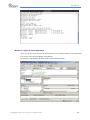
1
Qsan Q‐Series User Manual U400Q Series U600Q Series Version 8.13 July 2012 User Manual Copyright Copyright@2004~2012, Qsan Technology, Inc. All rights reserved. No part of this document may be reproduced or transmitted without written permission from Qsan Technology, Inc. Trademarks All products and trade names used in this manual are trademarks or registered trademarks of their respective companies. FW versions MXD Platform: U400Q / U600Q Series: FW 1.0.0 QCentral 2.1.0 Qsan Technology, Inc. 2F., No.23, Lane 583, Ruiguang Rd. Neihu Dist., Taipei 114 Taiwan, R.O.C. Tel: +886‐2‐7720‐2118 Fax: +886‐2‐7720‐0295 Email: [email protected] Website: www.QsanTechnology.com Copyright@2004~2012 Qsan Technology, Inc. All Rights Reserved. 2 User Manual 0 Preface About this manual This manual is the introduction of Qsan unified storage system and it aims to help users know the operations of the disk array system easily. Information contained in this manual has been reviewed for accuracy, but not for product warranty because of the various environments / OS / settings. Information and specification will be changed without further notice. For any update information, please visit www.QsanTechnology.com and your contact windows. Before reading this manual, it assumes that you are familiar with computer skills such as hardware, storage concepts and network technology. It also assumes you have basic knowledge of Redundant Array of Independent Disks (RAID), Storage Area Network (SAN), Network‐Attached Storage (NAS), Internet SCSI (iSCSI), Serial‐attached SCSI (SAS), Serial ATA (SATA), technology. CAUTION: Do not attempt to service, change, disassemble or upgrade the equipment’s components by yourself. Doing so may violate your warranty and expose you to electric shock. Refer all servicing to authorized service personnel. Please always follow the instructions in this user’s manual. Technical Support Thank you for using Qsan Technology, Inc. products; if you have any question, please e‐mail to [email protected]. We will answer your question as soon as possible. Tips and Cautions This manual uses the following symbols to draw attention to important safety and operational information. Symbol Meaning Copyright@2004~2012 Qsan Technology, Inc. All Rights Reserved. Description 3 User Manual TIP CAUTION Tips provide helpful information, guidelines, or suggestions for performing tasks more effectively. Cautions indicate that failure to take a specified action could result in damage to the software or hardware. Conventions The following table describes the typographic conventions used in this manual. Conventions Bold <Italic> [ ] square brackets { } braces | vertical bar / Slash underline Description Indicates text on a window, other than the window title, including menus, menu options, buttons, fields, and labels. Example: Click OK button. Indicates a variable, which is a placeholder for actual text provided by the user or system. Example: copy <source‐file> <target‐file>. Indicates optional values. Example: [ a | b ] indicates that you can choose a, b, or nothing. Indicates required or expected values. Example: { a | b } indicates that you must choose either a or b. Indicates that you have a choice between two or more options or arguments. Indicates all options or arguments. Indicates the default value. Example: [ a | b ] FCC and CE statements FCC statement This device has been shown to be in compliance with and was tested in accordance with the measurement procedures specified in the Standards and Specifications listed below and as indicated in the measurement report number: xxxxxxxx‐F Technical Standard: FCC Part 15 Class A (Verification) IC ICES‐003 CE statement This device has been shown to be in compliance with and was tested in accordance with the measurement procedures specified in the Standards and Specifications listed below and as indicated in the measurement report number: xxxxxxxx‐E Technical Standard: EMC DIRECTIVE 2004/108/EC Copyright@2004~2012 Qsan Technology, Inc. All Rights Reserved. 4 User Manual (EN55022 / EN55024) UL statement Rack Mount Instructions ‐ The following or similar rack‐mount instructions are included with the installation instructions: 1. Elevated Operating Ambient ‐ If installed in a closed or multi‐unit rack assembly, the operating ambient temperature of the rack environment may be greater than room ambient. Therefore, consideration should be given to installing the equipment in an environment compatible with the maximum ambient temperature (Tma) specified by the manufacturer. 2. Reduced Air Flow ‐ Installation of the equipment in a rack should be such that the amount of air flow required for safe operation of the equipment is not compromised. 3. Mechanical Loading ‐ Mounting of the equipment in the rack should be such that a hazardous condition is not achieved due to uneven mechanical loading. 4. Circuit Overloading ‐ Consideration should be given to the connection of the equipment to the supply circuit and the effect that overloading of the circuits might have on overcurrent protection and supply wiring. Appropriate consideration of equipment nameplate ratings should be used when addressing this concern. 5. Reliable Earthing ‐ Reliable earthing of rack‐mounted equipment should be maintained. Particular attention should be given to supply connections other than direct connections to the branch circuit (e.g. use of power strips). CAUTION: The main purpose of the handles is for rack mount use only. Do not use the handles to carry or transport the systems. The ITE is not intended to be installed and used in a home, school or public area accessible to the general population, and the thumbscrews should be tightened with a tool after both initial installation and subsequent access to the panel. Warning: Remove all power supply cords before service This equipment intended for installation in restricted access location. y Access can only be gained by SERVICE PERSONS or by USERS who have been instructed about the reasons for the restrictions applied to the location and about any precautions that shall be taken. y Access is through the use of a TOOL or lock and key, or other means of security, and is controlled by the authority responsible for the location. Copyright@2004~2012 Qsan Technology, Inc. All Rights Reserved. 5 User Manual CAUTION: Risk of explosion if battery is replaced by incorrect type. Dispose of used batteries according to the instructions. Copyright@2004~2012 Qsan Technology, Inc. All Rights Reserved. 6 User Manual Contents Chapter 0 PREFACE............................................................................................................................................ 3 ABOUT THIS MANUAL ....................................................................................................................................... 3 TECHNICAL SUPPORT ........................................................................................................................................ 3 TIPS AND CAUTIONS ......................................................................................................................................... 3 CONVENTIONS................................................................................................................................................. 4 FCC AND CE STATEMENTS ................................................................................................................................. 4 Chapter 1 OVERVIEW....................................................................................................................................... 11 PRODUCT OVERVIEW ...................................................................................................................................... 11 Model Comparison............................................................................................................................ 11 Package Contents.............................................................................................................................. 12 HARDWARE .................................................................................................................................................. 12 LCD Control Module.......................................................................................................................... 13 Disk Drive Assembly .......................................................................................................................... 13 Rear View .......................................................................................................................................... 14 RAID CONCEPTS ........................................................................................................................................... 17 RAID Levels........................................................................................................................................ 17 NAS CONCEPTS............................................................................................................................................. 18 ISCSI CONCEPTS ............................................................................................................................................ 18 Chapter 2 INSTALLATION ................................................................................................................................. 20 INSTALLATION OVERVIEW ................................................................................................................................ 20 Drive Slot Numbering........................................................................................................................ 20 System Installation and Deployment ................................................................................................ 21 POWER ON / OFF......................................................................................................................................... 24 Power On the System........................................................................................................................ 24 Power Off the System ....................................................................................................................... 25 Chapter 3 QUICK SETUP................................................................................................................................... 26 MANAGEMENT INTERFACES ............................................................................................................................. 26 LCM ................................................................................................................................................... 26 Copyright@2004~2012 Qsan Technology, Inc. All Rights Reserved. 7 User Manual Web UI .............................................................................................................................................. 27 MANAGEMENT SOFTWARE .............................................................................................................................. 28 Download QCentral........................................................................................................................... 28 Software Installation and Deployment ............................................................................................. 29 USING QCENTRAL SERVER IN CLIENT‐SERVER MODE ............................................................................................. 34 USING QCENTRAL CLIENT IN CLIENT‐SERVER MODE.............................................................................................. 36 USING QCENTRAL CLIENT IN STANDALONE MODE ................................................................................................ 38 QUICK SETUP VIA WIZARD ............................................................................................................................... 41 Chapter 4 BASIC CONFIGURATION ................................................................................................................... 44 INTERFACE HIERARCHY .................................................................................................................................... 44 OPERATION TAB: SUMMARY ............................................................................................................................ 45 Overview ........................................................................................................................................... 45 Utilization.......................................................................................................................................... 46 MENU: FILE .................................................................................................................................................. 47 Download MIB file ............................................................................................................................ 47 Dump to USB..................................................................................................................................... 47 MENU: CONFIGURATION ................................................................................................................................. 47 SUBMENU: SYSTEM ........................................................................................................................................ 47 System Setting .................................................................................................................................. 47 System............................................................................................................................................... 48 Date and Time................................................................................................................................... 49 Mail Setting ....................................................................................................................................... 49 Messenger......................................................................................................................................... 50 SNMP ................................................................................................................................................ 50 System Log Server............................................................................................................................. 51 Event Log Filter ................................................................................................................................. 52 Network Setting ................................................................................................................................ 52 SUBMENU: STORAGE ...................................................................................................................................... 56 Physical Disk...................................................................................................................................... 56 S.M.A.R.T........................................................................................................................................... 58 Pool ................................................................................................................................................... 58 ZFS..................................................................................................................................................... 60 Snapshot ........................................................................................................................................... 62 LUN ................................................................................................................................................... 63 SUBMENU: ACCOUNT ..................................................................................................................................... 64 Users ................................................................................................................................................. 64 Groups............................................................................................................................................... 66 Copyright@2004~2012 Qsan Technology, Inc. All Rights Reserved. 8 User Manual SUBMENU: SHARING ...................................................................................................................................... 67 Explorer............................................................................................................................................. 67 Shares................................................................................................................................................ 70 SUBMENU: SERVICES ...................................................................................................................................... 70 Data Services..................................................................................................................................... 70 CIFS.................................................................................................................................................... 71 NFS .................................................................................................................................................... 72 AFP .................................................................................................................................................... 72 FTP .................................................................................................................................................... 72 WebDAV............................................................................................................................................ 74 iSCSI................................................................................................................................................... 74 Connection........................................................................................................................................ 75 Directory Services ............................................................................................................................. 76 Backup............................................................................................................................................... 78 Amazon S3 ........................................................................................................................................ 78 Replication ........................................................................................................................................ 80 AntiVirus ........................................................................................................................................... 81 Settings ............................................................................................................................................. 82 Report ............................................................................................................................................... 83 SUBMENU: ENCLOSURE................................................................................................................................... 84 Hardware monitor ............................................................................................................................ 84 UPS.................................................................................................................................................... 84 MENU: VIEW ................................................................................................................................................ 85 SUBMENU: SUMMARY .................................................................................................................................... 85 Event ................................................................................................................................................. 86 MENU: MAINTENANCE ................................................................................................................................... 86 SUBMENU: UPGRADE FIRMWARE ...................................................................................................................... 86 System............................................................................................................................................... 86 Local Expander .................................................................................................................................. 87 Reset to Factory Default ................................................................................................................... 87 Reboot and Shutdown ...................................................................................................................... 88 Authentication .................................................................................................................................. 88 MENU: HELP ................................................................................................................................................ 88 Chapter 5 ACCESS SHARES FROM YOUR OPERATING SYSTEM........................................................................... 89 CIFS AND WINDOWS ..................................................................................................................................... 89 Method 1 : The address input in Explorer ........................................................................................ 89 Method 2 : The command line input from Start button ................................................................... 90 Copyright@2004~2012 Qsan Technology, Inc. All Rights Reserved. 9 User Manual Method 3 : Map a network drive in Explorer.................................................................................... 90 NFS AND LINUX............................................................................................................................................. 92 Redhat Linux 5 .................................................................................................................................. 92 Redhat Linux 6 .................................................................................................................................. 92 Open Solaris 10/11............................................................................................................................ 92 NFS AND VSHPERE5....................................................................................................................................... 93 AFP AND MAC OS X...................................................................................................................................... 93 FTP ............................................................................................................................................................ 94 Method 1 : Using command line shell .............................................................................................. 94 Method 2 : Using FTP client application ........................................................................................... 95 WEBDAV .................................................................................................................................................... 96 Method 1 : Windows 7 using Map Network Drive wizard ................................................................ 96 Method 2 : Using 3rd party WebDAV client application .................................................................. 100 Chapter 6 SOFTWARE APPLICATION............................................................................................................... 101 MICROSOFT ISCSI INITIATOR .......................................................................................................................... 101 Connect to iSCSI Target................................................................................................................... 101 Setup MPIO ..................................................................................................................................... 102 Setup MC/S ..................................................................................................................................... 104 Disconnect ...................................................................................................................................... 105 Chapter 7 GLOSSARY AND ACRONYM LIST ..................................................................................................... 107 Chapter 8 INDEX............................................................................................................................................ 109 Copyright@2004~2012 Qsan Technology, Inc. All Rights Reserved. 10 User Manual 1 Overview Product Overview This user manual describes how to set up and use the Qsan storage systems. There are four types of chassis available now. Q424 (4U24bays) Q316 (3U16bays) Q212 (2U12bays) The storage array, available in different configurations of GbE iSCSI and 10GbE iSCSI interfaces, provides a flexible, intelligent, network‐attached storage (NAS) solution for virtualized server environments and the growing demand for data storage. Qsan storage systems can provide non‐ stop service with a high degree of fault tolerance by using Qsan technology and advanced array management features. Model Comparison Qsan storage system XXXXQ‐Xxxx stands for the following models. XXXXQ stands for front‐end interfaces: y U400Q: 7 x GbE ports per controller. y U600Q: 2 x 10GbE ports + 3 x GbE ports per controller. X stands for { S }: Copyright@2004~2012 Qsan Technology, Inc. All Rights Reserved. 11 User Manual y S: Single controller only. xxx stands for chassis height and HDD bays. It can be { 424 | 316 | 212 }: y 424: 4U 24 bays with 3.5” HDD trays. y 316: 3U 16 bays with 3.5” HDD trays. y 212: 2U 12 bays with 3.5” HDD trays. Host Interface 7 x GbE iSCSI 2 x 10GbE iSCSI + 3 x GbE iSCSI 4U24 U400Q‐S424 3U16 U400Q‐S316 2U12 U400Q‐S212 U600Q‐S424 U400Q‐S316 U600Q‐S212 Package Contents The package contains the following items: y Qsan storage system (x1). y HDD trays (x24) (Q424). HDD trays (x16) (Q316). HDD trays (x12) (Q212). y Power cords (x3) (Q424). Power cords (x2) (Q316 / Q212). y RS‐232 cables (x2), one is for console (black color, phone jack to DB9 female), the other is for UPS (gray color, phone jack to DB9 male). y CD (x1). y Rail kit (x1 set). y Keys, screws for drives and rail kit (x1 packet). Hardware This section provides basic information about the hardware components. Q424 (4U24bays) Copyright@2004~2012 Qsan Technology, Inc. All Rights Reserved. Q316 (3U16bays) 12 User Manual Q212 (2U12bays) LCD Control Module There are five buttons to control LCM (LCD Control Module), including: c (up), d (down), ENT (Enter), ESC (Escape) and MUTE. 1 7 8 9 2 3 4 5 6 This table shows the items located on the LCD Control Module. Number 1 2 3 4 5 6 7 8 9 Description LCD display. Up button. Down button. ENT (Enter) button. ESC (Escape) button. MUTE button. Power LED: y Green: Power ON. y Off: Power OFF. Status LED: y Red: System failure. y Off: System OK. Access LED: y Blue: Host is accessing storage system. y Off: No host access attempts. Disk Drive Assembly Remove a drive tray. Then install a HDD. To install SAS / SATA drives: align the edge of the SAS / SATA drive to the back end of tray; the backplane can directly connect to SAS / SATA drives. Copyright@2004~2012 Qsan Technology, Inc. All Rights Reserved. 13 User Manual SAS / SATA Drive The front of each disk tray has four components: 3 4 1 2 This table provides details about the front components of a disk tray. Number 1 2 3 4 Description Power LED: y Green: Drive is inserted and good. y Red: Drive fails. y Off: No drive in the tray. Access LED: y Blue blinking: The drive is being accessed. y Off: The drive is not being accessed or no drive in the tray. Tray removal handle. Latch to release the tray and tray handle. Rear View There are three various chassises available now. The following examples show the U400Q series. Q424 chassis: Copyright@2004~2012 Qsan Technology, Inc. All Rights Reserved. 14 User Manual 4 5 6 8 1 7 3 2 This table describes the rear modules. Number 1 2 3 4 5 6 7 8 Description Controller 1 (CTRL 1). Dummy. Power Switch y |: ON. y O: OFF. Fan Module (FAN1 / FAN2). Fan Module (FAN3 / FAN4). Power Supply Unit (PSU1). Power Supply Unit (PSU2). Power Supply Unit (PSU3). Q316 chassis: 4 5 6 7 1 3 2 Q212 chassis: 2 1 6 4 3 7 5 Copyright@2004~2012 Qsan Technology, Inc. All Rights Reserved. 15 User Manual There are many various controllers available. With the exception of the host NAS ports, the connections are the same on all modules. U400Q‐S424 / U400Q‐S316 /U400Q‐S212 (7 x GbE) controller: 1 8 9 5 6 2 3 4 7 This table describes the rear components. Number 1 2 3 4 5 6 7 8 9 LED Description Ports (depending on model): y U400Q: 7 x GbE ports. y U600Q: 2 x 10GbE ports + 3 x GbE ports. LED (from left to right for Q424 / Q316, from right to left for Q224 / Q212) Controller health LED: y Green: Controller status normal. y Red: System booting or controller failure. Master slave LED (only for dual controllers): y Green: This is the Master controller. y Off: This is the Slave controller. Dirty cache LED: y Orange: Data on the cache waiting for flush to disks. y Off: No data on the cache. BBM LED (when status button pressed): y Green: BBM installed and powered. y Off: No BBM installed. BBM status button (used to check the battery when the power is off.): y If the BBM LED shows Green, then the BBM still has power to keep data on the cache. y If the BBM LED stays Off, then the BBM power has run out and it cannot provide power for the cache anymore. It needs to be recharged or replaced. Management port. Console port. RS 232 port for UPS. SAS JBOD expansion port. BBM slot. USB y No function. Reserved for the future design purpose. 10GbE Link LED (U600Q): y Orange: Asserted when a 1G link is established and maintained. y Blue: Asserted when a 10G link is establish and maintained. Copyright@2004~2012 Qsan Technology, Inc. All Rights Reserved. 16 User Manual 10GbE Access LED: y Yellow: Asserted when the link is established and packets are being transmitted along with any receive activity. CAUTION: Be aware that when Controller Health LED is in RED, please DO NOT unplug the controller from the system or turn off the power suddenly. This may cause unrecoverable damage, which will not be covered by warranty. U600Q‐S424 SFP+ / U600Q‐S316 SFP+ / U600Q‐S212 SFP+ (2 x 10GbE + 3 x GbE) controller: 1 8 9 5 6 2 3 4 7 RAID Concepts RAID is the abbreviation of Redundant Array of Independent Disks. The basic idea of RAID is to combine multiple drives together to form one large logical drive. This RAID drive obtains performance, capacity and reliability than a single drive. The operating system detects the RAID drive as a single storage device. RAID Levels There are various RAID levels with different degrees of data protection, data availability, and performance. A description of supported RAID levels follow: Type RAID 0 RAID 1 RAID 5 RAID 6 RAID 50 RAID 60 Description Disk striping. Disk mirroring over two disks. Striping with interspersed parity over the member disks. 2‐dimensional parity protection over the member disks. Striping over the member RAID 5 volumes. Striping over the member RAID 6 volumes. Copyright@2004~2012 Qsan Technology, Inc. All Rights Reserved. Min. No. of Drives 1 2 3 4 6 8 17 User Manual NAS Concepts NAS (Network‐Attached Storage) is file‐level computer data storage connected to a computer network providing data access to heterogeneous clients. NAS uses file‐based protocols such as NFS (popular on UNIX systems), SMB/CIFS (Server Message Block/Common Internet File System) (used with MS Windows systems), or AFP (used with Apple Macintosh computers). NAS units rarely limit clients to a single protocol. NAS provides both storage and a file system. This is often contrasted with SAN (Storage Area Network), which provides only block‐based storage and leaves file system concerns on the "client" side. SAN protocols are SCSI, Fibre Channel, iSCSI, ATA over Ethernet (AoE), or HyperSCSI. One way to loosely conceptualize the difference between a NAS and a SAN is that a NAS appears to the client OS (operating system) as a file server (the client can map network drives to shares on that server) whereas a disk available through a SAN still appears to the client OS as a disk, visible in disk and volume management utilities (along with client's local disks), and available to be formatted with a file system and mounted. iSCSI Concepts iSCSI (Internet SCSI) is a protocol which encapsulates SCSI (Small Computer System Interface) commands and data in TCP/IP packets for linking storage devices with servers over common IP infrastructures. iSCSI provides high performance SANs over standard IP networks like LAN, WAN or the Internet. Copyright@2004~2012 Qsan Technology, Inc. All Rights Reserved. 18 User Manual IP SANs are true SANs (Storage Area Networks) which allow several servers to attach to an infinite number of storage volumes by using iSCSI over TCP/IP networks. IP SANs can scale the storage capacity with any type and brand of storage system. In addition, it can be used by any type of network (Ethernet, Fast Ethernet, Gigabit Ethernet, and 10 Gigabit Ethernet) and combination of operating systems (Microsoft Windows, Linux, Solaris, Mac, etc.) within the SAN network. IP‐SANs also include mechanisms for security, data replication, multi‐path and high availability. Host 2 (initiator) iSCSI HBA Host 1 (initiator) NIC IP SAN iSCSI device 1 (target) iSCSI device 2 (target) Storage protocol, such as iSCSI, has “two ends” in the connection. These ends are initiator and target. In iSCSI, we call them iSCSI initiator and iSCSI target. The iSCSI initiator requests or initiates any iSCSI communication. It requests all SCSI operations like read or write. An initiator is usually located on the host side (either an iSCSI HBA or iSCSI SW initiator). The target is the storage device itself or an appliance which controls and serves volumes or virtual volumes. The target is the device which performs SCSI command or bridge to an attached storage device. Copyright@2004~2012 Qsan Technology, Inc. All Rights Reserved. 19 User Manual 2 Installation Installation Overview Before starting, prepare the following items: y A management computer with a Gigabit Ethernet NIC (recommend) on the same network as the Qsan storage system. y y Connection cables: All: Use CAT 5e, or CAT 6 (recommend) network cables for the management port. U400Q / U600Q: CAT 5e, or CAT 6 (recommend) network cables. U600Q SFP+: Fibre Channel cables. Prepare a storage system configuration plan by the network administrator. The plan should include network information for all network ports. If using static IP addresses, please prepare a list of the static IP addresses, the subnet mask, and the default gateway. y Switches All: Gigabit switches (optional) for connecting management port. U400Q / U600Q: Gigabit switches (recommended). Or Gigabit switches with VLAN / LCAP / Trunking (optional). y U600Q: 10 Gigabit switches with VLAN / LCAP / Trunking (optional). CHAP security information, including CHAP username and secret (optional). Drive Slot Numbering The drives can be installed into any slot in the enclosure. Slot numbering is reflected in Web UI. Copyright@2004~2012 Qsan Technology, Inc. All Rights Reserved. 20 User Manual Q424 Slot 1 Slot 7 Slot 13 Slot 19 Slot 2 Slot 8 Slot 14 Slot 20 Slot 3 Slot 9 Slot 15 Slot 21 Slot 4 Slot 10 Slot 16 Slot 22 Slot 5 Slot 11 Slot 17 Slot 23 Slot 6 Slot 12 Slot 18 Slot 24 Slot 1 Slot 5 Slot 9 Slot 13 Slot 2 Slot 6 Slot 10 Slot 14 Slot 3 Slot 7 Slot 11 Slot 15 Slot 4 Slot 8 Slot 12 Slot 16 Slot 1 Slot 4 Slot 7 Slot 10 Slot 2 Slot 5 Slot 8 Slot 11 Slot 3 Slot 6 Slot 9 Slot 12 Q316 Q212 System Installation and Deployment Using the following instructions to install and deploy the storage system. y Install the BBM (Battery Backup Module) in their appropriate controllers if needed. BBM supports hot pluggable. Regardless of the system is turned on or off. Remove the cover of BBM. Insert the BBM. Use two screws to tighten the BBM. y At the rear, check that the Master Controller is in its slot (CTRL 1). y If desired, install the optional Slave Controller in its slot (CTRL 2, only for dual‐controller). CAUTION: When running on dual controller mode, please make sure both controllers have the same DIMM on each corresponding memory slot. Failing to do so will result in controller malfunction, which will not be covered by warranty. Copyright@2004~2012 Qsan Technology, Inc. All Rights Reserved. 21 User Manual y Install the Rail Kit onto the unit and insert it into the rack. CAUTION: The system is very heavy. It’s recommend that a mechanical lifter or at least two persons be used to raise and align the system to prevent injury during installation. Use care when inserting or removing a system into or out of a rack to prevent the accidental tipping or the rack causing damage or personal injury. y Install the disk drives. y Connect the management port cable and data port cables on the network plan, the topology examples are on the following. Copyright@2004~2012 Qsan Technology, Inc. All Rights Reserved. 22 User Manual U400Q: U600Q: y Connect the console cable and UPS as the following. Copyright@2004~2012 Qsan Technology, Inc. All Rights Reserved. 23 User Manual Using RS‐232 cable for UPS (gray color, phone jack to DB9 male) to connect from controller to APC Smart UPS serial cable (DB9 female side), and then connect the serial cable to APC Smart UPS. CAUTION: It may not work when connecting the RS‐232 cable for UPS (gray color, phone jack to DB9 male) to APC Smart UPS directly. y Attach the power cords and power on the system. y Start the configuration. Power ON / OFF Power On the System The power switch is located at the rear of panel. To turn the system ON, press power switch to “|”. After you turn the power ON, the system performs a booting process which takes a few minutes. CAUTION: Be aware that in the first few seconds after power on the system the Controller Health LED is in RED. This is normal because the system is still booting. The Controller Health LED will turn Green in a few seconds. Copyright@2004~2012 Qsan Technology, Inc. All Rights Reserved. 24 User Manual Power Off the System If it becomes necessary to power down the system, it is recommended using a normal, controlled shutdown form through either the LCM or Web UI to ensure all data is flushed from the cache first. Shutdown using LCM At the LCM: y Power off the system using a normal shutdown. Press ENT button. Press d (down) twice to show “Reboot/Shutdown”, and press ENT button. Press d (down) once to show “Shutdown”, and press ENT button. Press c (up) once to highlight “Yes”, and press ENT button. y System shutdown begins. y When the “System Shutdown” message is displayed, turn the power switch to OFF “O”. Shutdown using QCentral Client Login QCentral Client: y Select Maintenance ‐> Reboot and Shutdown. y Click the Shutdown icon. y When the “System Shutdown” message is displayed on the LCM, turn the power switch to OFF “O”. Copyright@2004~2012 Qsan Technology, Inc. All Rights Reserved. 25 User Manual 3 Quick Setup Management Interfaces There are several management methods to manage the storage system, described on the following. LCM After booting up the system, the following screen shows management port IP and model name. Take an example of U400Q‐S424. 192.168.10.50 Qsan U400Q-S424 ← To access the LCM options, use the ENT (Enter) button, ESC (Escape) button, c (up) and d (down) to scroll through the functions. This table describes the function of each item. Function System Info. Description Display system information including firmware version and amount of RAM. Alarm Mute Mutes an alarm after an error occurs. View IP Setting Display current IP address, subnet mask, and gateway. Change IP config Set IP address, subnet mask, and gateway. There are 2 options: DHCP (Get IP address from DHCP server) or static IP. Reset IP & Admin Reset management port IP or reset admin password to 1234 Password Reset/Shutdown Reset or shutdown the system. WARNING or ERROR events displayed on the LCM are automatically filtered by the LCM default filter. The filter setting can be changed in the Web UI under System configuration ‐> Notification setting. Copyright@2004~2012 Qsan Technology, Inc. All Rights Reserved. 26 User Manual This table displays the LCM menu hierarchy. Main L1 System Info. Alarm Mute View IP Setting <IP Addr> Qsan <Model> cd L2 Firmware Version <n.n.n> RAM Size <nnnn> MB cYes Nod IP Config <Static IP / DHCP / BOOTP> IP Address <192.168.010.050 > IP Subnet Mask <255.255.255.0> IP Gateway <192.168.010.254 > DHCP BOOTP L3 cYes Nod cYes Nod Adjust IP address Adjust Subnet mask Adjust Gateway IP Subnet Mask Static IP IP Gateway Reset IP admin password Reset/ Shutdown L5 IP Address Change IP Config L4 Apply IP cYes Nod Setting cYes Nod & Reset IP Reset admin cYes Nod password Reset cYes Nod Shutdown cYes Nod CAUTION: To prevent data loss, when powering down the storage system, it is recommended to execute Reset/Shutdown ‐> Shutdown ‐> Yes to flush the data from the cache to the physical disks. Web UI Qsan unified storage provides a simplified web user interface to download QCentral management software. Details are described in the following section . Copyright@2004~2012 Qsan Technology, Inc. All Rights Reserved. 27 User Manual Management Software Qsan unified storage management uses QCentral software. It’s a Qsan's overall management software made of all necessary functions to monitor, administer, and configure Qsan's Q series systems. QCentral provides you easy and quick management to all high availability functions and advanced functions and it’s also a highly portable software by using Java‐based programming. There are no additional installation and server hardware requirements, and you can easily access all your storage systems with a server, laptop, or mobile device locally and over LAN. Download QCentral Qsan unified storage provides a web user interface to download QCentral management software. It supports most common web browsers. Be sure to connect the LAN cable to the management port of the Qsan unified storage system. The default IP setting is DHCP, check the LCM to find the IP address. If your network does not have DHCP server, you will need to configure a static IP address. Enter the IP address into your browser to display the authentication screen. http://<IP Address> (e.g.: http://192.168.10.50) To access the Web UI, you have to enter a user name and password. The initial defaults for administrator login are: y User name: admin y Password: 1234 When the password has been verified, the home page is displayed. The following examples show the U400Q. Copyright@2004~2012 Qsan Technology, Inc. All Rights Reserved. 28 User Manual Menu Bar Options Operation Area y Click QCentral to download QCentral software for installation. y Click Java to download JRE (Java Runtime Environment). Software Installation and Deployment There are standalone and client‐Server modes in QCentral software. Standalone mode can access Qsan storage directly. Client‐Server mode is centralized management. The access right of client to the storage is controlled by QCentral Server. If you install the client‐server mode, please see the following diagram and deploy. Copyright@2004~2012 Qsan Technology, Inc. All Rights Reserved. 29 User Manual QCentral Client QCentral Client QCentral Client QCentral Server F400Q-D212 P300Q-D316 P500Q-D424 U600Q-D424 S300Q-D224 First, install QCentral software. For the standalone mode, QCentral can be installed in one host. For the client‐server mode, both QCentral client and server program can be installed in one host or can be divided into several hosts. QCentral server program is installed in one server, and QCentral client programs are installed in other hosts. The following is the installation steps. 1. Run QSAN_QCentral_Setup‐2.1.0‐x86‐en.msi , click Next button. 2. Check the License Agreement, and then click Next button. Copyright@2004~2012 Qsan Technology, Inc. All Rights Reserved. 30 User Manual 3. Select Standalone or Client‐Server mode. and then click Next button. 4. If you select Standalone mode, change the location if necessary, and then click Next button. If you select Client‐Server mode, please jump to next step. Copyright@2004~2012 Qsan Technology, Inc. All Rights Reserved. 31 User Manual 5. It’s Client‐Server mode. Select to install Server or Client Application, or both. Change the location if necessary, otherwise click Next button. 6. Click Install button. Copyright@2004~2012 Qsan Technology, Inc. All Rights Reserved. 32 User Manual 7. Done, click Finish button. The QCentral software contains the following items: y QCentral Server: It’s a Windows based program. (It’s available in Client‐Server mode.) y QCentral Client: It’s a Java based program. JRE (Java Runtime Environment) is required. JRE can be download in http://www.java.com/ y Uninstall QCentral: Uninstall the QCentral programs. Copyright@2004~2012 Qsan Technology, Inc. All Rights Reserved. 33 User Manual Using QCentral Server in Client‐Server mode This section describes the main page of the QCentral server. Please run the program in Start ‐> All Programs ‐> QSAN ‐> QCentral ‐> QCentral Server. The main page is displayed below. There are two tabs in the main page. The following describes the functions: y System: it displays a list of Qsan products in the network environment. And Login operation to every Qsan storage. y Account: it can manage users, groups and their privileges for client side. Take an example of getting the authorization to a system. 1. Select a storage system in the list. 2. Click Login button. It will display a login dialog. Enter the username and password of the system. 3. If the username and password are correct, The Auth column of the system changes from No to Yes. Copyright@2004~2012 Qsan Technology, Inc. All Rights Reserved. 34 User Manual This section describes the operations of Account tab. The Account tab screenshot is displayed below. Take an example of getting the authorization to a system. 1. Select a group name. 2. Click Access button. It will pop up a window. Multi‐select the systems to be controlled by the group member. And then click OK button. Copyright@2004~2012 Qsan Technology, Inc. All Rights Reserved. 35 User Manual 3. The access list will be displayed in the bottom right table. Using QCentral Client in Client‐Server mode This section describes the main page of the QCentral client. It’s a Java based program. JRE (Java Runtime Environment) is required. Run the program in Start ‐> All Programs ‐> QSAN ‐> QCentral ‐ > QCentral Client. It will display a dialog box for authentication. Enter the QCentral server IP address, account and password which are created in QCentral server. The initial default for admin login is on the following. y Server: 127.0.0.1 (This example is that QCentral server and client are executed on the same host. If not, please enter the QCentral server IP address.) y Account: admin (Enter the account which is created in the QCentral server.) Copyright@2004~2012 Qsan Technology, Inc. All Rights Reserved. 36 User Manual y Password: 1234 (Enter the password which is inputted in the QCentral server.) When the password has been verified, the main page of the QCentral client is displayed. Menu Function Icon Options Operation Tabs Indicators and Icons Managed Product Area Operation Area Event Log Area The following describes the main page: y Menu: QCentral client drop‐down menu options. y Function Icon: QSnap, VD Clone and QReplica funtion icons. If the icon is grayed, the function is disabled. y Managed Product Area: This area lists all system names and IP addresses which are authorized to manage by the account. Copyright@2004~2012 Qsan Technology, Inc. All Rights Reserved. 37 User Manual y Operation Tabs: There are three operation tabs above the operation area. Click it can switch the operation area. y Indication and Icons: In Summary tab, There are up to six indicators at the top‐right corner. y Operation Area: This area displays the information which is related to the selected product in managed product area. y Event Log Area: This area displays the event logs of all managed products. You can select the system name in the managed products area. The related information is displayed in the operation area. Using QCentral Client in Standalone mode The same as above. Run the program in Start ‐> All Programs ‐> QSAN ‐> QCentral ‐> QCentral Client. The main page of the QCentral client is displayed. It will scan all Qsan storages in LAN and display in “Managed Product Area”. Click the storage IP which you want to manage. Menu Function Icon Options Managed Product Area Operation Tabs Operation Area Event Log Area Copyright@2004~2012 Qsan Technology, Inc. All Rights Reserved. 38 User Manual It will popup an authentication dialog. The initial default for admin login of the Qsan storage is on the following. y Account: admin y Password: 1234 When the password has been verified, the main page of the QCentral client is displayed. Menu Function Icon Options Operation Tabs Indicators and Icons Managed Product Area Operation Area Event Log Area There are up to six indicators at the top‐right corner. In Configuration tab, a chassis graphic is displayed below. Move the cursor over the graphics. A mouse‐over tip will pop up to briefly describe each part the cursor is pointed at. Clicking on the graphic will get you to the corresponding management page. Copyright@2004~2012 Qsan Technology, Inc. All Rights Reserved. 39 User Manual Menu Function Icon Options Operation Tabs Intuitive Graph Managed Product Area Operation Area Event Log Area The following describes the main page: y Menu: QCentral client drop‐down menu options. y Function Icon: Qsnap, VD Clone and QReplica funtion icons. If the icon is grayed, the function is disabled. y Managed Product Area: This area lists all system names and IP addresses which are authorized to manage by the account. y Operation Tabs: There are three operation tabs above the operation area. Click it can switch the operation area. y Intuitive Graph: In configuration tab, there are two graphs of the front and rear panel. Mouse over the component will display the information. Clicking it will jump to the related operation in the operation area. y Operation Area: This area displays the informations which are related to the selected product in managed product area. y Event Log Area: This area displays the event logs of all managed products. Copyright@2004~2012 Qsan Technology, Inc. All Rights Reserved. 40 User Manual Quick Setup via Wizard The menu Wizard provides a quick setup wizard. Take an example of using wizard. 1. Click menu Wizard. 2. Enter the System name, click Next button. 3. Setup the system time and NTP (Network Time Protocol) server. When it is done, click Next button. Copyright@2004~2012 Qsan Technology, Inc. All Rights Reserved. 41 User Manual 4. Setup the management port. There are three options: DHCP, BOOTP and specify a Static IP address. The default setting is DHCP. When it is done, click Next button. 5. Setup a pool. Select a RAID level from the drop‐down list. click Next button.. Copyright@2004~2012 Qsan Technology, Inc. All Rights Reserved. 42 User Manual 6. At the confirmation message, click Finish button. 7. It will create a pool which includes two file systems and one volume. 8. The Public folder shares CIFS, NFS, AFP, FTP data services. And the volume attaches a LUN for iSCSI usage. Copyright@2004~2012 Qsan Technology, Inc. All Rights Reserved. 43 User Manual 4 Basic Configuration Interface Hierarchy This table describes the hierarchy of the web GUI. Menu Bar File Configuration /System L1 Download MIB file Dump to USB Exit System setting Shares CIFS NFS AFP FTP WebDAV iSCSI Connection L2, Button or Menu Save /Cancel OK / Cancel Exit QCentral program System / Date and time / Mail setting / Messenger / SNMP / System log server / Event log filter Options: IP settings / DNS settings / Create link aggregation / Set VLAN ID / Become default gateway / Enable jumbo frame Select enclosure Options: Set free disk / Set dedicated spare Select enclosure Options: Expand / Delete Options: Create / Edit / Delete / Take snapshot / Auto snapshot Select ZFS Options: Take snapshot Select volume Options: Attach / Detach Options: Add / Delete / Edit / Change password Options: Add / Delete / Edit Options: Create / Edit file system / Create folder / Delete file system / Take snapshot / Auto snapshot / Add share / Delete UserHome Options: Remove share CIFS settings Start / StopNFS settings Start / Stop AFP service FTP settings Start / Stop WebDAV service Change entity property File service / iSCSI service Change Domain settings Amazon S3 Replication Options: Add Options: Add Settings Report Options: AntiVirus settings Export report Hardware monitor Select enclosure Change UPS property. Service status / Pool status / Controller information Network setting Configuration /Storage Physical disk S.M.A.R.T. Pool ZFS Snapshot LUN Configuration /Accounts Configuration /Sharing Configuration /Services /Data services Configuration /Services /Directory services Configuration /Services /Backup Configuration /Services /AntiVirus Configuration /Enclosure View/Summary Users Groups Explorer UPS Overview Copyright@2004~2012 Qsan Technology, Inc. All Rights Reserved. 44 User Manual View/Event Maintenance Wizard Help Utilization Event log Upgrade firmware Reset to factory default Reboot and shutdown Authentication Quick setup About CPU loading / Memory usage / Management / LAN Save as / Clear all Options: Clear event log System / Local expander Yes /No Reboot / Shutdown Account / Password About QCentral Operation Tab: Summary The menu View ‐> Summary or Summary tab of the operation area is for accessing the Overview and Utilization option tabs. Overview The Overview gives you a big picture of system health and storage capacity information. It includes data service status, pool status, and controller information. The controller information includes firmware version, CPU type, installed system memory, serial numbers, backplane ID and status. Indicators There are up to six indicators at the top‐right corner. This table describes the indicators and icons. Copyright@2004~2012 Qsan Technology, Inc. All Rights Reserved. 45 User Manual Icon Description RAID indicator: y Green: All RAID groups are functioning. y Red: A RAID group is degraded or has failed. Temperature indicator: y Green: Temperature is normal. y Red: Temperature is too high. Voltage indicator: y Green: Voltage values are normal. y Red: Voltage values are out of range. UPS indicator: y Green: UPS is functioning or no UPS is connected. y Red: UPS connection has failed. Fan indicator: y Green: Fan is working well. y Red: Fan failed. Power indicator: y Green: Power supplies are connected and working well. y Red: A power supply has failed or is no longer connected. Utilization The Utilization tab (also in menu View ‐> Utilization) provides to display the utilization of the system. It includes CPU loading, memory usage, LAN traffic and disk throughput. Copyright@2004~2012 Qsan Technology, Inc. All Rights Reserved. 46 User Manual Menu: File The menu File is for accessing the Download MIB file, Dump to USB and Exit option. Download MIB file The Download MIB file provides to download MIB file for SNMP usage. Dump to USB The Dump to USB provides to dump debug messages to USB drive. Select the drive and click OK button. The debug message is a zip file, send it to us when you need to support. Menu: Configuration The menu Configuration is for accessing the System, Storage, Accounts, Sharing, Services and Enclosure options. Submenu: System The menu Configuration ‐> System is for accessing the System setting and Network setting options. System Setting The menu Configuration ‐> System ‐> System setting or System setting tab of the operation area is for accessing the System, Date and Time, Mail setting, Messenger, SNMP, System Log Server and Event Log Filter option tabs. Copyright@2004~2012 Qsan Technology, Inc. All Rights Reserved. 47 User Manual System The System icon is used to setup the system name, system indication, buzzer and auto shutdown. The default system name is composed of the model name and the serial number of this system. The options available in this dialog: y System name: To change the System name, highlight the old name and type in a new one. y System indication: Enable it to turn on the system LED for locating this system in the racks. y Buzzer: Enable it to let the system make a sound like a bee buzzing when the system is abnormal. y Auto shutdown: Enable it to let the system shutdown automatically when the voltage or temperature is out of the normal range. For better data protection, it is recommended to check Auto Shutdown. When it is done, click OK button. Copyright@2004~2012 Qsan Technology, Inc. All Rights Reserved. 48 User Manual Date and Time The Date and Time icon is used to setup the system time and NTP (Network Time Protocol) server. The options available in these dialogs: y Date and time: To change the current date, time and time zone settings. y NTP server: Enter the IP address to synchronize the time from an NTP server. When it is done, click OK button. Mail Setting The Mail setting icon is used to enter up to three mail addresses for receiving the event notifications. Fill in the necessary fields and click Send test mail to test whether it is workable. Some mail servers check the Mail‐from address and need the SMTP relay setting for authentication. TIP: Please make sure the DNS server IP is well‐setup in Network setting ‐> DNS setting. So the event notification mails can be sent successfully. You can also select which levels of event logs which you would like to receive. The default setting only includes WARNING and ERROR event logs. Copyright@2004~2012 Qsan Technology, Inc. All Rights Reserved. 49 User Manual When it is done, click OK button. Messenger The Messenger icon is used to setup pop‐up messages via Windows messenger (not MSN). The options available in this dialog: y Messenger: You must enable the Messenger service in Windows (Start ‐> Control Panel ‐> Administrative Tools ‐> Services ‐> Messenger). It allows up to three Messenger addresses. You can choose the alert levels which you would like to receive. The default setting only includes WARNING and ERROR event logs. When it is done, click OK button. SNMP The SNMP icon is used to setup SNMP traps (for alerting via SNMP). Copyright@2004~2012 Qsan Technology, Inc. All Rights Reserved. 50 User Manual The options available in this dialog: y SNMP: It allows up to three SNMP trap addresses. The default community setting is public. You can choose the alert levels which you would like to receive. The default setting only includes WARNING and ERROR event logs. There are many SNMP tools avaiable on the internet. SNMPc: http://www.snmpc.com/ Net‐SNMP: http://net‐snmp.sourceforge.net/ When it is done, click OK button. System Log Server The System Log Server icon is used to setup alerts via the syslog protocol. The options available in this dialog: y System log server:: Fill in the necessary fields for syslog service. The default port is 514. You can choose the alert levels which you would like to receive. The default setting only includes WARNING and ERROR event logs. There are some syslog server tools avaiable on the internet for Windows. WinSyslog: http://www.winsyslog.com/ Kiwi Syslog Daemon: http://www.kiwisyslog.com/ Most UNIX systems have built‐in syslog daemon. Copyright@2004~2012 Qsan Technology, Inc. All Rights Reserved. 51 User Manual When it is done, click OK button. Event Log Filter The Event Log Filter tab is used to setup event log filter. The options available in this dialog: y Event log filter: You can choose the alert levels which you would like to have shown on LCM. The default setting for LCM only includes WARNING and ERROR event logs. When it is done, click OK button. Network Setting The menu Configuration ‐> System ‐> Network setting or Network setting tab of the operation area is for accessing the Management network port and LAN ports. It is used to change IP addresses of network ports. The various controllers have different network port configurations: y U400Q: 1 x GbE Management port + 6 x GbE ports per controller. y U600Q: 1 x GbE Management port + 2 x 10GbE ports + 2 x GbE ports per controller. Each port must be assigned its own IP address. They need to be configured in multi‐homed mode, or a present link aggregation / trunking mode. When multiple LAN ports are set up in link aggregation or trunking mode, all the LAN ports share the same IP address. The following example shows the U400Q series (1 x GbE Management port + 6 x GbE ports). Copyright@2004~2012 Qsan Technology, Inc. All Rights Reserved. 52 User Manual We define that the management port is a special network port. It can download QCentral software via HTTP, but it can not be used as WebDAV service nor linked aggregation with other LAN ports. In addition, GbE and 10GbE LAN ports can not link aggregation each other either. The following table describes the relationship with the service and the network ports. Service HTTP (Download QCentral page) CIFS NFS AFP WebDAV iSCSI Link aggregation Management port Yes Yes Yes Yes No Yes No LAN1 ~ LANn No Yes Yes Yes Yes Yes Yes This table shows the column descriptions. Column Name Name LAG LAG# VLAN DHCP Protocol IPv4 Gateway MTU MAC address Link Description Management port or LAN ports. Link aggregation status. Link aggregation number. VLAN number. Use DHCP , BOOTP or static IP. Use IPv4 or IPv6(Coming soon). IP address. Gateway IP address. Jumbo frame size MAC address Network link status: y Green light: Link up y Red light: Link down. The options available in this tab: y IP Settings: There are three options: DHCP, BOOTP and specify a Static IP address. The default setting is DHCP. Copyright@2004~2012 Qsan Technology, Inc. All Rights Reserved. 53 User Manual y DNS: If necessary, the IP address of DNS server can be entered or changed here. The DNS settings will be applied to all network ports, which means you ONLY need to select one of the network ports and start DNS setting. y Create link aggregation: The default mode is no link aggregation. Trunking, LACP (Link Aggregation Control Protocol) or Balance‐alb settings can be selected from dropdown list. At least two NICs must be selected for network bonding to work. Copyright@2004~2012 Qsan Technology, Inc. All Rights Reserved. 54 User Manual Trunking: Configures multiple network ports in parallel to increase the link speed beyond the limits of any single port. LACP: It is part of IEEE specification 802.3ad that allows several physical ports to be bundled together to form a single logical channel. This increases the bandwidth and provides automatically failover when link status fails on a port. Balance‐alb: Adaptive load balancing includes balance‐tlb plus receive load balancing (rlb) for IPV4 traffic, and does not require any special switch support. The receive load balancing is achieved by ARP negotiation. The bonding driver intercepts the ARP Replies sent by the local system on their way out and overwrites the source hardware address with the unique hardware address of one of the slaves in the bond such that different peers use different hardware addresses for the server. y Set VLAN ID: VLAN is a logical grouping mechanism implemented on switch device. VLANs are collections of switching ports that comprise a single broadcast domain. It allows network traffic to flow more efficiently within these logical subgroups. Please consult your network switch user manual for VLAN setting instructions. Most of the work is done at the switch part. All you need to do is to make sure that your iSCSI port's VLAN ID matches that of switch port. If your network environment supports VLAN, you can click Set VLAN ID to change the configurations. Fill in VLAN ID and Priority settings to enable VLAN. VLAN ID: VLAN ID is a 12‐bit number. Its range is from 2 to 4094, while 0, 1, and 4095 are reserved for special purposes. Priority: The PCP (Priority Code Point)) is a 3‐bit number and reserved for QoS. The definition comply with IEEE 802.1p protocol, ranging from 0 to 7, with 0 as the default value. In normal cases, you don't need to set this value. Using the default will do just fine. TIP: If network ports are assigned with VLAN ID before creating aggregation takes place, aggregation will remove VLAN ID. You need to repeat the steps to set VLAN ID for the aggregation group. Copyright@2004~2012 Qsan Technology, Inc. All Rights Reserved. 55 User Manual y Become default gateway: The default gateway can be changed by clicking Become default gateway. There can be only one default gateway. To remove the default gateway, right click to bring out the menu and select Disable default gateway. y Enable jumbo frame: The MTU (Maximum Transmission Unit)) size can be enabled by checking Enable jumbo frame. Maximum jumbo frame size is 9000 bytes. To disable jumbo frame, right click to bring out the menu and select Disable jumbo frame. CAUTION: VLAN ID, jumbo frames for both the switching hub and HBA on host must be enabled. Otherwise, the LAN connection can not work properly. Submenu: Storage The menu Configuration ‐> Storage or Configuration tab of the operation area is for accessing the Physical disk, S.M.A.R.T., Pool, ZFS, Snapshot, LUN options. Physical Disk Go to Configuration ‐> Storage ‐> Physical Disk or Configuration ‐> Physical disk tab of the operation area or clicking the drive icon on the intuitive graph gives you the hard drive status. The drop‐down list enables you to switch between the local system and any expansion JBOD systems attached. This table shows the column descriptions. Column Name Slot Size (GB) Pool Name Status Health Description The position of a hard drive. The button next to the number of slot shows the functions which can be executed. Capacity of hard drive. The unit can be displayed in GB or MB. Pool name. The status of the hard drive: y Online: the hard drive is online. y Rebuilding: the hard drive is being rebuilt. y Transition: the hard drive is being migrated or is replaced by another disk when rebuilding occurs. y Scrubbing: the hard drive is being scrubbed. The health of the hard drive: Copyright@2004~2012 Qsan Technology, Inc. All Rights Reserved. 56 User Manual Usage SSD Vendor Serial Type Write cache Standby Readahead Command queuing y Good: the hard drive is good. y Failed: the hard drive is failed. y Error Alert: S.M.A.R.T. error alert. y Read Errors: the hard drive has unrecoverable read errors. The usage of the hard drive: y RAID disk: This hard drive has been set to a RAID group. y Free disk: This hard drive is free for use. y Dedicated spare: This hard drive has been set as dedicated spare of a RG. y Global spare: This hard drive has been set as global spare of all RGs. HDD or SSD. Hard drive vendor. Hard drive serial number. Hard drive rate: y SAS 6Gb/s. y SAS 3Gb/s. y SATA 6Gb/s. y SATA 3Gb/s. y SATA 1.5Gb/s. Hard drive write cache is enabled or disabled. The default value is Enabled. HDD auto spindown to save power. The default value is Disabled. This feature makes data be loaded to disk’s buffer in advance for further use. The default value is Enabled. Newer SATA and most SCSI disks can queue multiple commands and handle one by one. The default value is Enabled. The drop‐down options by clicking mouse right button are avaiable on this tab: y Set Free disk: Make the selected hard drive be free for use. y Set Dedicated spare: Set a hard drive to dedicated spare of the selected pool. y Set Cache: Set a SSD to be used as cache. (This option is only visible when the physical disks is an SSD.) Take an example to set the fourth PD as dedicated spare disk. 1. Check Set Dedicated spare at the fourth PD. 2. If there is any pool which is in protected RAID level and can be set with dedicate spare disk, select one pool, and then click OK button. Copyright@2004~2012 Qsan Technology, Inc. All Rights Reserved. 57 User Manual S.M.A.R.T. S.M.A.R.T. (Self‐Monitoring Analysis and Reporting Technology) is a diagnostic tool for hard drives to deliver warning of drive failures in advance. The menu Configuration ‐> Storage ‐> S.M.A.R.T. or clicking S.M.A.R.T. tab of the operation area provides users a chance to take actions before a possible drive failure. S.M.A.R.T. measures many attributes of the hard drive all the time and inspects the properties of hard drives which are close to be out of tolerance. The advanced notice of possible hard drive failure gives users precautions to back up hard drive or replace the hard drive. This is much better than hard drive crash when it is writing data or rebuilding a failed hard drive. The numbers displayed are real‐time value. The number in parenthesis is the threshold value. The threshold values from different hard drive vendors are different; please refer to hard drive vendors’ specification for details. S.M.A.R.T. only supports SATA drives. SAS drives do not have this function and will show N/A in the web page. Pool The menu Configuration ‐> Storage ‐> Pool or Configuration ‐> Pool tab of the operation area provides various functions to manage storage pool such as create, expand, set home directory, delete, or view the status of the pools. This table shows the column descriptions. Column Name Copyright@2004~2012 Qsan Technology, Inc. All Rights Reserved. Description 58 User Manual Name Total (GB) Used (GB) Free (GB) Capacity Dedup Status Home RAID set slot Spare slot Cache slot Pool name. Total capacity of this pool. Used capacity of this pool. Free capacity of this pool. The percentage or the capacity. The status of the deduplication. The status of the pool: y Online: the pool is good. y Failed: the pool fails. y Rebuild: the pool is being rebuilt. The home directory is in the pool or not. The physical disk slots of the RAID set. The spare physical disk slot. The cache physical disk slot. Functions in the right click menu: y Create: Create a pool. y Expand: Expand the pool. y Set home directory: Assign home directory to the pool. (This option is only visible when home directory is not assigned.) y Delete: Delete the pool. The pool can be deleted when there is no file system or volume in it. Take an example of creating a pool. 1. Click the Create by clicking mouse right button. 2. Enter a Name for the pool. 3. Use the drop‐down list to select a RAID level. Copyright@2004~2012 Qsan Technology, Inc. All Rights Reserved. 59 User Manual 4. Select disks from both local or expansion JBOD systems, and click >> to complete the selection. The selected disks are displayed at the Selected box. When it’s done, click Next button. 5. Optionally, configure the following: y Write Cache: It’s to enable or disable the write cache option of hard drives. The default value is Disabled. y Standby: It’s to enable or disable the auto spindown function of hard drives, when this option is enabled and hard drives have no I/O access after certain period of time, they will spin down automatically. The default value is Disabled. y Readahead: It’s to enable or disable the read ahead function. The default value is Enabled. y Command queuing: It’s to enable or disable the hard drives’ command queue function. The default value is Enabled. 6. Click Next button. 7. At the confirmation message, click Finish button. ZFS The menu Configuration ‐> Storage ‐> ZFS or Configuration ‐> ZFS tab of the operation area provides functions to manage ZFS datasets such as create, edit, delete, take snapshot, auto snapshot or view the status of the ZFS. Copyright@2004~2012 Qsan Technology, Inc. All Rights Reserved. 60 User Manual This table shows the column descriptions. Column Name Name Type Quota (GB) Reserved (GB) Used (GB) Free (GB) Dedup Compress Copies Schedule Original #Snapshot Description The name of the file system or volume. File system or volume. The Quota of the file system or volume. Reserved capacity of the file system or volume. Used capacity of the file system or volume. Free capacity of the file system or volume. The status of the deduplication. The status of the compression. The number of the copies. (More explanation in Tip.) The status of the schedule. The original file system or volume of the clone. The number of the snapshots. Functions in the right click menu: y Create: Click the Create button to create a file system or a volume. y Edit: Edit the properties of the file system or volume. y Delete: Delete the file system or volume. y Take snapshot: Take a snapshot. y Auto snapshot: Set auto snapshot schedule. Take an example of creating a file system or a volume. 1. Click the Create by clicking mouse right button.. 2. Enter a Name for the file system or volume. 3. Use the drop‐down list to select a Pool. 4. Select Type, Property and No. of data copies. Copyright@2004~2012 Qsan Technology, Inc. All Rights Reserved. 61 User Manual 5. Enter the Size for the file system or volume. 6. Click OK button. TIP: “No. of data copies” in Create File System or Volume UI is used to create mirroring of data to avoid data corruption. When the original file corrupts, the system will use the extra “copy” to recover the corrupt file. The value of two means that when you copy a 10MB file, it will take up 20MB space. The value of three means that it will take up extra double space to store the same data in the same storage pool. Users will not be able to see the actual extra copies. They are controlled by the file system. Snapshot The menu Configuration ‐> Storage ‐> Snapshot or Configuration ‐> Snapshot tab of the operation area provides functions to manage snapshot activities such as take snapshot, rollback, clone, delete, or view the status of the snapshots. Snapshot can only be applied to the whole file system or volume. Snapshot can not be applied to specific shared folders. This table shows the column descriptions. Column Name Name Used (MB) Refer (GB) Created time Description The snapshot name. The amount of snapshot space that has been used. The refer capacity of the file system or volume. The time the snapshot is created. Functions in the right click menu: y Take snapshot: Manually take a snapshot. y Rollback: Rollback the snapshot file system or volume. y Clone: Clone the file system or volume. y Delete: Delete the snapshot file system or volume. Take an example of taking a snapshot. 1. Click the Take snapshot button. Copyright@2004~2012 Qsan Technology, Inc. All Rights Reserved. 62 User Manual 2. Use the drop‐down list to select a ZFS name. 3. Enter a Snapshot name for the snapshot. 4. Click OK button. LUN The menu Configuration ‐> Storage ‐> LUN or Configuration ‐> LUN tab of the operation area provides functions to manage iSCSI volumes such as attach, detach or view the status of logical unit numbers for each volume. This table shows the column descriptions. Column Name Host Target LUN Permission ZFS name Description iSCSI node name for access control or a wildcard (*) for access by all hosts. The number of the target. The number of the LUN assigned. The permission level: y Read‐write. y Read‐only. The name of the volume assigned to this LUN. Functions in the right click menu: y Attach: Attach a logical unit number to a volume. y Detach: Detach a logical unit number from a volume. Take an example of attaching a LUN. 1. Click the Attach button. Copyright@2004~2012 Qsan Technology, Inc. All Rights Reserved. 63 User Manual 2. Select the volume from the drop‐down list. 3. Enter an iSCSI node name for access control, or fill‐in wildcard (*) for access by all hosts. 4. Select the Target number from the drop‐down list. 5. Select the LUN number from the drop‐down list. 6. Choose the Permission level. 7. Click OK button. The matching rules of access control are determined by the time the attaching of the LUN is created in ascending order. For example: there are 2 LUN rules for the same volume, rule 1 is “*”, LUN 0; and rule 2 is “iqn.host1”, LUN 1. A host named “iqn.host2” can login successfully because it matches the rule 1. Wildcard “*” and “?” are allowed in this field. “*” can replace any words. “?” can replace only one character. For example: y “iqn.host?” ‐> “iqn.host1” and “iqn.host2” are accepted. y “iqn.host*” ‐> “iqn.host1” and “iqn.host12345” are accepted. This field can not accept comma, so “iqn.host1, iqn.host2” stands for a long string, not 2 iqns. Submenu: Account The menu Configuration ‐> Account is for accessing the Users and Groups options. Users The menu Configuration ‐> Account ‐> Users or Account ‐> Users tab of the operation area provides functions to manage local user accounts such as add, delete, edit, change password or view the status of the users. Local user accounts and domain user accounts are displayed separately by selecting the drop down list. Copyright@2004~2012 Qsan Technology, Inc. All Rights Reserved. 64 User Manual Domain user accounts are only for display purpose. You can not edit domain account or change the password of domain account. This table shows the column descriptions. Column Name User name Group Quota (GB) Used (%) Email Description Description The account name. The user belongs to the groups. User quota space. The percentage of the quota usage. User’s email. User’s description. Functions in the right click menu: y Add: Create a user. y Delete: Delete the user. y Edit: Edit the user. y Change password: Change the user’s password. Take an example of creating an account. 1. Click Add by clicking mouse right button. Copyright@2004~2012 Qsan Technology, Inc. All Rights Reserved. 65 User Manual 2. Enter the Username, Password, and Retype password. The other fields are optional. 3. Click OK button to create an account. TIP: The password is required to be at least 12 and up to 16 alphanumeric characters. This is because of UnifiedAUTH mechanism that will integrate with iSCSI CHAP account. iSCSI CHAP account requires that the password needs to be 12 to 16 characters. Groups The menu Configuration ‐> Account ‐> Groups or Account ‐> Groups tab of the operation area provides functions to manage local groups such as add, delete, edit, or view the status of the groups. Local groups and domain groups are displayed separately by selecting the drop down list. This table shows the column descriptions. Column Name Group name Description The group name. Copyright@2004~2012 Qsan Technology, Inc. All Rights Reserved. 66 User Manual #User Description The number of users that belong to this group. Group’s description. Functions in the right click menu: y Add: Create a group. y Delete: Delete the group. y Edit: Edit the group. Take an example of creating a group. 1. Click Add by clicking mouse right button. 2. Enter the Group name. The other fields are optional. 3. Click OK button to create a group. Submenu: Sharing The menu Configuration ‐> Sharing is for accessing the Explorer and Shares options. Explorer The menu Configuration ‐> Sharing ‐> Explorer or Sharing ‐> Explorer tab of the operation area provides to create file system/volume, edit file system/volume, delete file system/volume, create folder for file system, take snapshot, auto snapshot, add share for file system, attach LUN for volume or browse the whole storage pool structure. Copyright@2004~2012 Qsan Technology, Inc. All Rights Reserved. 67 User Manual Functions in the right click menu for file system (file‐based access): y Create: Create a file system or volume. y Edit file system: Edit the file system. y Create folder: Create folder on the file system. y Delete file system: Delete the file system. y Take snapshot: Take a snapshot on the file system. y Auto snapshot: Set auto snapshot on the file system. y Add share: Add share for the data services. y Edit share: Edit share for the data services. y Remove share: Remove share for the data services. Functions in the right click menu for volume (block‐based access): y Edit volume: Edit the volume. y Delete volume: Delete the volume. y Take snapshot: Take a snapshot on the volume. y Auto snapshot: Set auto snapshot on the volume. y Attach LUN: Attach LUN to the volume. y Detach LUN: Detach LUN from the volume. Take an example of creating a file system or a volume. 1. Click the Create by clicking mouse right button. Copyright@2004~2012 Qsan Technology, Inc. All Rights Reserved. 68 User Manual 2. Enter a Name for the file system or volume. 3. Use the drop‐down list to select a Pool. 4. Select Type, Property and No. of data copies. 5. Enter the Size for the file system or volume. 6. Click OK button. Take an example of sharing a file system. 1. Click the Add share ‐> CIFS, NFS, AFP, FTP by clicking mouse right button. The following dialog will pop up for data service setting and access control setting. 2. Click Select user(s) and group(s) to share the folder to designated users and groups. 3. Check one or more data services that you want to apply to the folder. Please click Settings button of each data service for more details. 4. Click CIFS Settings button, it will pop up a dialog. Copyright@2004~2012 Qsan Technology, Inc. All Rights Reserved. 69 User Manual 5. Enter the Shared Name. And then click OK button. 6. Click OK button to finish adding a share. Shares The menu Configuration ‐> Sharing ‐> Shares or Sharing ‐> Shares tab of the operation area provides to remove the share or view the status of the shares. This table shows the column descriptions. Column Name Description CIFS/NFS/AFP/FTP/WebDAV Share name for CIFS/NFS/AFP/FTP. name CIFS/NFS/AFP/FTP/WebDAV The status of CIFS/NFS/AFP: y Green light: the data service is enabled. y Red light: the data service is disabled. The drop‐down option by clicking mouse right button is avaiable on the share: y Remove share: Remove the share. Submenu: Services The menu Configuration ‐> Services is for accessing the Data Services, Directory services, Backup and AntiVirus options. Data Services The menu Configuration ‐> Services ‐> Data services or Data services tab of the operation area provides to enable, disable and configure the data services. Currently, it supports CIFS, NFS, AFP, FTP, WebDAV, and iSCSI data services. All data services are enabled by default. Copyright@2004~2012 Qsan Technology, Inc. All Rights Reserved. 70 User Manual CIFS The CIFS(Common Internet File System) tab is used to setup CIFS protocol. The CIFS is a network protocol that offers file services for Windows computers. Qsan unified storage provides CIFS capability without the need for a Windows server in the network. Starting this service will open the following ports on the Qsan unified storage system: y TCP 139 (smbd) y TCP 445 (smbd) y UDP 137 (nmbd) y UDP 138 (nmbd) Click Change button to enable/disable the CIFS protocol and setup its configurations. This table shows the row descriptions. Row Name Server description Workgroup WINS server 1 IP address WINS server 2 IP address Description Default is “Welcome to CIFS server”. Maximum length is 256 characters. Default is “Workgroup”. Maximum length is 16 characters. WINS Server IP Address. Default is empty. If it’s empty, the name resolution priority is DNS only. Otherwise, the name resolution priority is WINS server first, and then DNS. The same as above. When it is done, click OK button. Copyright@2004~2012 Qsan Technology, Inc. All Rights Reserved. 71 User Manual NFS The NFS(Network File System) tab is used to setup NFS protocol. NFS is a protocol for sharing files and directories on a network among Linux machines and Unix machines. Starting this service will open the following ports on the Qsan unified storage system: y TCP 111 (rpcbind) y TCP 2049 (nfsd) y UDP 111 (rpcbind) y Additionally, mountd and rpcbind will each bind to a randomly available UDP port. Click Change button to enable/disable the NFS protocol. AFP The AFP(Apple Filing Protocol) tab is used to setup AFP protocol. The AFP is a network protocol that offers file sharing services for Mac computers. Starting this service will open the following ports on the Qsan unified storage system: y TCP 548 (afpd) y TCP 4799 (cnid_metadata) y UDP 5353 and a random UDP port (avahi). Click Change button to enable/disable the AFP protocol. FTP The FTP(File Transfer Protocol) tab is used to setup FTP protocol. Qsan unified storage allows you to configure the FTP server so that users can browse and download data using their web browser or FTP client software. FTP is easy to use and it is cross‐platform. All major operating systems have FTP client function. Copyright@2004~2012 Qsan Technology, Inc. All Rights Reserved. 72 User Manual Click Change button to enable/disable the FTP protocol and setup its configurations. This table shows the row descriptions. Row Name Login banner Clients Connections Login attempts Timeout Description Configurable login banner. Default is “Welcome to FTP server”. Max characters is 256. The maximum number of simultaneous clients, default is 5, range is 1 ~ 4096. The maximum number of connections per IP address, default is 2, range is 1 ~ 32. The maximum number of attempts before client is disconnected, default is 3, range is 3 ~ 32. The maximum client idle time in seconds before client is disconnected, default is 60 (sec), valid values are 30, 60, 300, 600, 1800, 3600. The minimum passive port, default is 49152, range is 1024 ~ 65535. Minimum passive port Maximum passive The maximum passive port, default is 65534, range is 1024 ~ 65535. port Upload The upload bandwidth, in KB/s, default is 0 (no limit) bandwidth(KB/s) Download The download bandwidth, in KB/s, default is 0 (no limit) bandwidth(KB/s) Copyright@2004~2012 Qsan Technology, Inc. All Rights Reserved. 73 User Manual When it is done, click OK button. WebDAV The WebDAV(Web Distributed Authoring and Versioning) tab is used to setup WebDAV protocol. It is an extension of HTTP v1.1 protocol that allows users to manage files across different operating system platforms. Starting this service will open the following ports on the Qsan unified storage system: y TCP 80 (httpd) Click Change button to enable/disable the WebDAV protocol. iSCSI y The iSCSI(Internet SCSI) tab is used to setup iSCSI entity name for block‐based access. iSCSI is a protocol standard that allows the consolidation of storage data. iSCSI allows Qsan unified storage to act like a storage area network (SAN) over an existing Ethernet network. Specifically, it exports disk devices over an Ethernet network that iSCSI clients (called initiators) can attach to and mount. Click Change button to change the iSCSI entity name. Copyright@2004~2012 Qsan Technology, Inc. All Rights Reserved. 74 User Manual When it is done, click OK button. Connection y The Connection tab is used to display the connections of the data services. This table shows the column descriptions on File service. Column Name Protocol User Client Server Description Data service protocol. Current login user. The client information. The server information. This table shows the column descriptions on iSCSI service. Most of the options are standard parameters used in the negotiation between the initiator and target when an iSCSI connection is created. Column Name No. Initiator Name Initiator IP Description Number. It displays the host computer name. It displays the host computer IP. Copyright@2004~2012 Qsan Technology, Inc. All Rights Reserved. 75 User Manual Target Name InitialR2T Immed. data MaxDataOutR2T MaxDataBurstLen It displays the controller name. InitialR2T (Initial Ready to Transfer) is used to turn off either the use of a unidirectional R2T command or the output part of a bidirectional command. The default value is Yes. Immed. data (Immediate Data) sets the support for immediate data between the initiator and the target. Both must be set to the same setting. The default value is Yes. MaxDataOutR2T (Maximum Data Outstanding Ready to Transfer) determines the maximum number of outstanding ready to transfer per task. The default value is 1. MaxDataBurstLen (Maximum Data Burst Length) determines the maximum SCSI data payload. The default value is 256kb. Directory Services The menu Configuration ‐> Services ‐> Directory services or Directory services tab of the operation area provides three directory services. Default is Standalone, which supports local account only. The others are Active Directory for Windows and LDAP services. Only one directory service can be enabled at all time. No two directory services can be enabled at the same time. Switching directory service will result in losing Access Control List of all shares from the previous directory service. Click Change button to select the directory service : y Standalone Standalone support local user/group accounts only. It’s the default setting. When it is done, click OK button. Copyright@2004~2012 Qsan Technology, Inc. All Rights Reserved. 76 User Manual y Active Directory Active Directory service supports Windows Server 2003 and 2008 Active Directory to manage the accounts. The maximum number of AD users and groups is 65536. Enter the settings of Active Directory above. When it is done, click OK button. If the information is correct, the AD accounts will be added in Account ‐> Domain user and Account ‐> Domain group. It will take some time to download the accounts at the first time. And then it will synchronize with the server automatically. Or you may set the duration in minutes for how often U400Q/U600Q should synchronize with the AD server. y LDAP LDAP(Light‐weighted Directory Access Protocol) service supports LDAP version3 to manage the accounts. The maximum number of LDAP users and groups is 65536. Copyright@2004~2012 Qsan Technology, Inc. All Rights Reserved. 77 User Manual Enter the settings of LDAP above. When it is done, click OK button. If the information are correct, the accounts will be added to Account ‐> Domain user and Account ‐> Domain group. Base DN : The base distinguished name (DN) indicates where in the LDAP directory you wish to load users and groups. It is the top level of the LDAP directory tree to be used when searching for resources. Suppose that all user accounts and groups are located in the “Users” folder under your domain. In LDAP form, it is cn=Users,dc=<your domain>. Let’s say your domain is aaa.bbb.com. The Base DN you should put in is cn=Users,dc=aaa,dc=bbb,dc=com. Admin DN : By default, the administrator DN is in the form cn=Administrator,dc=<your domain>. Using previous example, The Admin DN should be put in is cn=Administrator,dc=aaa, dc=bbb,dc=com. TIP: Please contact your LDAP server administrator for the correct login parameters for Base DN, Admin DN, User base DN, and Group base DN. Backup The menu Configuration ‐> Services ‐> Backup or Backup tab of the operation area provides functions to set up the backup services. Currently, it supports Amazon S3 and Replication services. Both Amazon S3 and replication services are applied to the whole file system or volume, which is the right next level to the storage pool. None of backup services can be applied to specific shared folders. Amazon S3 y The Amazon S3 tab is used to setup the popular cloud backup service provided by Amazon. Before using the service, you must register an Amazon S3 account first at http://aws.amazon.com/s3/. y There is no limit to the number of how many Amazon S3 tasks can be created. If you experience slow system performance, please reduce the Amazon S3 tasks. Copyright@2004~2012 Qsan Technology, Inc. All Rights Reserved. 78 User Manual Functions in the right click menu: y Add: Add a backup task to Amazon S3 service. y Edit: Edit the task. y Delete: Delete the task. y Start: Start the task. y Stop: Stop the task. y Schedule: Schedule the task. Take an example of adding a task. 1. Click Add by clicking mouse right button. 2. Enter the Job name, select the Local path, and enter the folder. 3. Select the Backup type, Upload or Download, enter the Access key, Private Key and the Bucket/Folder for Amazon S3 settings. Check the box when you need to delete extra files in the destination folder. 4. Click OK button to create a task. Copyright@2004~2012 Qsan Technology, Inc. All Rights Reserved. 79 User Manual Replication y The Replication tab is used to setup the replication service. It support local cloning and remote replication to other Qsan unified storage arrays. y There is no limit to the number of how many local cloning and remote replication tasks can be created. If you experience slow system performance, please reduce the replication tasks. Functions in the right click menu: y Add: Add a replication task. y Delete: Delete the task. y Start: Start the task. y Stop: Stop the task. y Schedule: Schedule the task. Take an example of adding a task. 1. Click Add by clicking mouse right button. 2. Enter the Task name, and select a file system or volume to replicate. Then click Next button. Copyright@2004~2012 Qsan Technology, Inc. All Rights Reserved. 80 User Manual 3. Select the Local cloning or Remote replication. Remote replication needs to enter the target IP, username and password. And then click Next button. 4. Select the target pool and enter a name. And then click Next button. 5. At the confirmation message, click Finish button. AntiVirus The menu Configuration ‐> Services ‐> AntiVirus or AntiVirus tab of the operation area is for accessing the Settings and Report option tabs. Qsan unified storage provides 24/7 around the clock protection for your precious data and ensures a safe and virus‐free data access environment. First, you need to have a antivirus server that supports ICAP(Internet Content Adaption Protocol) function in your network environment. Supported antivirus server is Symantec Scan Engine 5.0 or later version. The diagram below shows how Qsan unified storage interacts with the antivirus server. Copyright@2004~2012 Qsan Technology, Inc. All Rights Reserved. 81 User Manual Qsan Unified Storage 1 Windows, Linux, Mac Users 4 3 2 Symantec Scan Engine 1. Users try to write a file into Qsan unified storage. 2. Qsan unified storage send the file through ICAP to antivirus server for scanning. 3. Antivirus server scans the file, repairs it if it is infected, and returns the clean file to Qsan unified storage. 4. Qsan unified storage writes the clean file to the storage, puts the scan result in the report, and informs the user that the write is complete. Settings ICAP is a lightweight protocol developed to allow scanning and modification of web content passing through a web proxy. Being designed a lightweight protocol for high performance security checks, it is well‐suited for use with unified storage appliance and file sharing services. The purpose is real‐time monitoring all incoming files (writes) for continuous protection. The actions taken when virus is spotted are determined by ICAP server. The infected files are displayed in Report tab. Copyright@2004~2012 Qsan Technology, Inc. All Rights Reserved. 82 User Manual Click Change button to change the settings: Enter the settings of AntiVirus server IP. The default port number o ICAP is 1344. The other fields are optional. Add the exclude file type and shares if needed. When it is done, click OK button. Report The menu Configuration ‐> Services ‐> AntiVirus ‐> Report or AntiVirus ‐> Report tab of the operation area provides to report the infected files. y Export report: Click button to save the report as a text file with the file name format as “log‐ ModelName‐SerialNumber‐Date‐Time.txt”. Copyright@2004~2012 Qsan Technology, Inc. All Rights Reserved. 83 User Manual Submenu: Enclosure The menu Configuration ‐> Enclosure is for accessing the Hardware monitor and UPS options. Hardware monitor Go to Configuration ‐> Enclosure ‐> Hardware Monitor by clicking Hardware Monitor tab of the operation area or clicking PSU, FAN on the intuitive graph. It will display the information of current voltages and temperatures. UPS The menu Configuration ‐> Enclosure ‐> UPS or clicking UPS tab of the operation area is used to set up a UPS (Uninterruptible Power Supply). Currently, the system only supports and communicates with Smart‐UPS series by APC (American Power Conversion Corp, http://www.apc.com/) and Magatec UPS. Copyright@2004~2012 Qsan Technology, Inc. All Rights Reserved. 84 User Manual TIP: Connection with other vendors of UPS can work well, but they have no such communication features with the system. First, connect the system to UPS via the included cable for communication. (The cable plugs into the serial cable that comes with the UPS.) Then set up the shutdown values for when the power goes out. This table shows the available options and their descriptions. Options UPS Type Description Select UPS Type: y None: No UPS or other vendors. y Smart‐UPS: APC UPS. y Megatec‐UPS: Megatec UPS. Shutdown battery When below the setting level, the system will shutdown. Setting level to level (%) “0” will disable UPS. Shutdown delay If power failure occurs and system power can not recover after the time (s) setting, the system will shutdown. Setting delay to “0” will disable the function. Shutdown UPS Select ON, when power is gone, UPS will shutdown by itself after the system shutdown successfully. After power comes back, UPS will start working and notify system to boot up. OFF will not. Status The status of UPS: y Detecting… y Running y Unable to detect UPS y Communication lost y UPS reboot in progress y UPS shutdown in progress y Batteries failed. Please change them NOW! Battery level (%) Current power percentage of battery level. The system will shutdown when either Shutdown battery level (%) or Shutdown delay (s) reaches the condition. User should set these values carefully. Menu: View The menu View is for accessing the Summary and Event options. Submenu: Summary The menu View ‐> Summary or Summary tab of the operation area is for accessing the Overview and Utilization option tabs. Please see Operation Tab: Summary at the beginning section of this chapter for more details. Copyright@2004~2012 Qsan Technology, Inc. All Rights Reserved. 85 User Manual Event The menu View ‐> Event or Event log tab of the operation area provides a log or event messages. In filter setting, check INFO, WARNING, or ERROR to display those particular events. The options are available on this tab: y SaveAs: Click SaveAs button to save the whole event log as a text file with file name “log‐ ModelName‐SerialNumber‐Date‐Time.txt”. y Clear All: Click Clear All button to clear all event logs. The event log is displayed in reverse order which means the latest event log is on the first / top page. Menu: Maintenance The menu Maintenance is for accessing the Upgrade firmware, Reset to factory default, Reboot and shutdown and Authentication options. Submenu: Upgrade firmware The menu Maintenance ‐> Upgrade firmware is for accessing the System and Local expander options. System The menu Maintenance ‐> Upgrade firmware ‐> System is used to upgrade controller firmware. Copyright@2004~2012 Qsan Technology, Inc. All Rights Reserved. 86 User Manual Please prepare new controller firmware file named “xxxx.bin” in local hard drive, then click Browse to select the file. Click OK button to start upgrading the firmware. When upgrading, there is a percentage displayed in the Managed Product Area. After finished upgrading, the system must reboot manually to make the new firmware took effect. Local Expander The menu Maintenance ‐> Upgrade firmware ‐> Local expander is used to upgrade local expander firmware. Reset to Factory Default The menu Maintenance ‐> Reset to factory default allows users to reset the system configurations back to the factory default settings. The default values are: y Admin password: 1234 Copyright@2004~2012 Qsan Technology, Inc. All Rights Reserved. 87 User Manual y IP address: DHCP Reboot and Shutdown The menu Maintenance ‐> Reboot and shutdown is used to reboot or shutdown the system. Before powering off the system, it is highly recommended to execute Shutdown function to flush the data from cache onto the physical disks. The step is important for data protection. Authentication The menu Maintenance ‐> Authentication is used to authenticate the system. If the password of the system is changed, the authentication is needed. Menu: Help The menu Help is for accessing the About option. Copyright@2004~2012 Qsan Technology, Inc. All Rights Reserved. 88 User Manual 5 Access shares from your operating system There are 5 data services provided by U400Q and U600Q. This chapter will show you how to access shares from different operating systems. We will introduce CIFS/Samba, NFS, FTP, AFP, and WebDAV. Before you can access the shares, please make sure that you have enable file sharing services and related settings in Submenu : Sharing of Chapter 4. CIFS and Windows There are several ways to access a network share in Windows XP and Windows 7 operating systems. It all follows Windows UNC (Universal Naming Convention) format. Syntax : \\<NAS system name>\<share name> \\<IP address of NAS>\<share name> <NAS system name> can be found from menu bar Configuration ‐> System setting and double click on System. <IP address of NAS> is the IP address of one of the network ports. It can be found from menu bar Configuration ‐> Network Setting. Method 1 : The address input in Explorer Open a Windows Explorer from Start button or by pressing Start key + E. In the address input, put in the share path and press Enter. Please refer to the screenshot below. Copyright@2004~2012 Qsan Technology, Inc. All Rights Reserved. 89 User Manual Windows will pop up a dialog requesting for account and password. Please put in your account and password. When the authentication is clear, the share is ready for you to use as follows : Method 2 : The command line input from Start button Click Start button to bring up the start menu. In the command line input, put in the share path and press Enter. The rest is the same as described in Option 1. Method 3 : Map a network drive in Explorer Please follow the steps below to map a network share from Qsan unified storage to a drive letter. The network share will be automatically mapped the next time you boot your Windows. Step 1 : Open a Windows Explorer from Start button or by pressing Start key + E. Go to Tools and select Map network drive. Copyright@2004~2012 Qsan Technology, Inc. All Rights Reserved. 90 User Manual Step 2 : Select the drive letter you like. Put in the share path in Folder. Make sure you check Reconnect at logon. Click Finish. Step 3 : You may find a new drive with the letter you just selected in Explorer. You may start using the new drive then. Copyright@2004~2012 Qsan Technology, Inc. All Rights Reserved. 91 User Manual NFS and Linux U400Q/U600Q supports NFS version 3 and version 4. If version 4 connection can not be established, the system will automatically try to establish the connection using version 3 protocol. Before using the NFS shares, please make sure the NFS settings of the shares are properly configured. Redhat Linux 5 When mounting a file system in Redhat Linux 5, Redhat Linux 5 uses NFS version 3 by default. Use the following syntax to mount an NFS share. Please make sure you add the keyword – nfs‐share before the share name. It represents the absolute path that the end user doesn’t need to know. mount <IP address of NAS>:/nfs‐share/<share name> <mount point> For example : mount 192.168.8.180:/nfs‐share/SQL_DB2 /mnt/nas Redhat Linux 6 The default attempt will try to use NFS version 4 protocol to set up connection in Redhat Linux 6. Use the following syntax to mount an NFS share. mount <IP address of NAS>:/<share name> <mount point> For example : mount 192.168.8.180:/SQL_DB2 /mnt/nas Open Solaris 10/11 Open Solaris 10/11 will use NFS version 4 as default. Use the following syntax to mount an NFS share. mount ‐F nfs ‐o rw <IP address of NAS>:/<share name> <mount point> For example : mount ‐F nfs ‐o rw 192.168.8.180:/SQL_DB2 /mnt/nas Copyright@2004~2012 Qsan Technology, Inc. All Rights Reserved. 92 User Manual NFS and vShpere5 If you want to use U400Q/U600Q as vSphere 5 storage through NFS connection, please make sure you export the NFS share with read/write access rights. In the vSphere 5 UI setting for NFS share, please use the following syntax. /nfs‐share/<share name> <insert screenshot> AFP and Mac OS X In Finder, go to “Go” and select “Connect to Server”. Put in the network port IP address that you want to access. Click “Connect”. It will bring up a window requesting account and password. Please put in your account and password. Click “Connect”. A window with all accessible shares for AFP protocol will pop up for you to select the share you want to connect to. Click “Ok”. Copyright@2004~2012 Qsan Technology, Inc. All Rights Reserved. 93 User Manual There you go. The share is ready for you to access. FTP FTP is the basic file transfer tool provided in almost all operating systems. You may use FTP function through command line shell, FTP client, or web browsers. Method 1 : Using command line shell In Windows XP or Windows 7, open a command line window and use FTP command – “ftp”. Enter your account and password. The share is available for you to access. In Redhad Linux , it looks like the screenshot below. Copyright@2004~2012 Qsan Technology, Inc. All Rights Reserved. 94 User Manual Method 2 : Using FTP client application There are a lot of FTP client tools in Windows platform such as WSFTP, FileZilla. In Linux X‐Window environment, there are gFTP, WXftp, and LLNL XFTP. For example, using FileZilla in Windows looks like the screenshot below. Copyright@2004~2012 Qsan Technology, Inc. All Rights Reserved. 95 User Manual WebDAV U400Q/U600Q WebDAV service supports the following operating systems : y 32bit Windows : Windows XP SP2, Windows 7 SP1, Windows Server 2008 SP1 y 64bit Windows operating systems have issues to support WebDAV service. We recommend using 3rd party WebDAV client applications. y 32bit Redhat Linux 5 and 6 y 64bit Redhat Linux 6 If you are using Windows XP or Vista, you may need to install a Windows update KB907306. If you are using Windows 7, please make sure WebClient service is enabled through Component Services. For more related information, please check WebDAV client interoperability at http://svnbook.red‐ bean.com/en/1.6/svn.webdav.clients.html Method 1 : Windows 7 using Map Network Drive wizard From Windows Explorer, go to Tools and select Map Network Drive. From Network and Sharing Center in the Control Panel, go to Tools and select Map Network Drive. Copyright@2004~2012 Qsan Technology, Inc. All Rights Reserved. 96 User Manual From the Computer icon on Desktop, right click on Computer icon and select Map Network Drive. When the wizard appears, click Connect to a Web site that you can use to store your documents and pictures. Copyright@2004~2012 Qsan Technology, Inc. All Rights Reserved. 97 User Manual Follow the instructions and click Next. Select Choose a custom network location and click Next. Copyright@2004~2012 Qsan Technology, Inc. All Rights Reserved. 98 User Manual In Internet or network address input, put in the WebDAV share in the following syntax. http://<IP address>: 50000/<WebDAV share> Please make sure you put in the port number 50000. Put in the required account and password information. You may name the network location. Here we simply use the default as 192.168.122.112. You may access the web folder now. Copyright@2004~2012 Qsan Technology, Inc. All Rights Reserved. 99 User Manual Method 2 : Using 3rd party WebDAV client application Recommended tools include WebDrive, NetDrive, or Bitkinex. Copyright@2004~2012 Qsan Technology, Inc. All Rights Reserved. 100 User Manual 6 Software Application Microsoft iSCSI initiator Here are the step by step instructions of how to setup Microsoft iSCSI Initiator. Please visit Microsoft website for latest iSCSI initiator. This example is based on Microsoft Windows Server 2008 R2. Connect to iSCSI Target 1. Run Microsoft iSCSI Initiator. 2. Input IP address or DNS name of the target. And then click Quick Connect button. 3. Select the target name, and then click Done button. Copyright@2004~2012 Qsan Technology, Inc. All Rights Reserved. 101 User Manual 4. It can connect to an iSCSI disk now. Setup MPIO 1. If running MPIO, please continue. 2. Click Discovery tab to connect the second path. 3. Click Discover Portal button. Enter the IP address or DNS name of the target. Copyright@2004~2012 Qsan Technology, Inc. All Rights Reserved. 102 User Manual 4. Click OK button. 5. Click Targets tab, select the second path, and then click Connect button. 6. Enable Enable multi‐path checkbox. Then click OK button. Copyright@2004~2012 Qsan Technology, Inc. All Rights Reserved. 103 User Manual 7. Done, it can connect to an iSCSI disk with MPIO. Setup MC/S 1. If running MC/S, please continue. 2. Select one target name, click Properties button. 3. Click MCS button to add additional connections. 4. Click Add button. 5. Click Advanced button. Copyright@2004~2012 Qsan Technology, Inc. All Rights Reserved. 104 User Manual 6. Select Initiator IP and Target portal IP, and then click OK button. 7. Click Connect button. 8. Click OK button. 9. Done. Disconnect 1. Select the target name, click Disconnect button, and then click Yes button. Copyright@2004~2012 Qsan Technology, Inc. All Rights Reserved. 105 User Manual 2. Done, the iSCSI device disconnect successfully. Copyright@2004~2012 Qsan Technology, Inc. All Rights Reserved. 106 User Manual Glossary and Acronym List Common Terminology Item RAID PD Pool ZFS LUN GUI RO DS DG SCSI SAS S.M.A.R.T. WWN HBA NIC BBM Description Redundant Array of Independent Disks. There are different RAID levels with different degree of data protection, data availability, and performance to host environment. The Physical Disk belongs to the member disk of one specific RAID group. A collection of removable media. One pool consists of one or several RAID sets. ZFS is a combined file system and logical volume manager designed by Sun Microsystems. The features of ZFS include data integrity verification against data corruption modes, support for high storage capacities, integration of the concepts of file system and volume management, snapshots and copy‐on‐write clones, continuous integrity checking. Logical Unit Number. A logical unit number (LUN) is a unique identifier which enables it to differentiate among separate devices (each one is a logical unit). Graphic User Interface. Set the volume to be Read‐Only. Dedicated Spare disks. The spare disks are only used by one specific RG. Others could not use these dedicated spare disks for any rebuilding purpose. DeGraded mode. Not all of the array’s member disks are functioning, but the array is able to respond to application read and write requests to its virtual disks. Small Computer Systems Interface. Serial Attached SCSI. Self‐Monitoring Analysis and Reporting Technology. World Wide Name. Host Bus Adapter. Network Interface Card. Battery Backup Module iSCSI Terminology Item iSCSI LACP MPIO MC/S MTU CHAP Description Internet Small Computer Systems Interface. Link Aggregation Control Protocol. Multi‐Path Input/Output. Multiple Connections per Session Maximum Transmission Unit. Challenge Handshake Authentication Protocol. An optional security Copyright@2004~2012 Qsan Technology, Inc. All Rights Reserved. 107 User Manual iSNS mechanism to control access to an iSCSI storage system over the iSCSI data ports. Internet Storage Name Service. Copyright@2004~2012 Qsan Technology, Inc. All Rights Reserved. 108 User Manual Index A AFP ..................................................................................... 72 Change ............................................................................ 73 Amazon S3 .......................................................................... 78 Add ................................................................................. 79 Delete .............................................................................. 79 Edit.................................................................................. 79 Schedule.......................................................................... 79 Start................................................................................. 79 Stop ................................................................................. 79 Apple Filing Protocol .......................................................... 72 Authentication ..................................................................... 87 B Balance-alb.......................................................................... 56 BBM (Battery Backup Module) .......................................... 21 C CE Statement......................................................................... 4 CIFS .................................................................................... 71 Change ............................................................................ 71 Common Internet File System ............................................. 71 Connection .......................................................................... 75 D Date and Time ..................................................................... 50 Date and Time................................................................. 50 NTP Server...................................................................... 50 Directory services Active Directory.............................................................. 77 LDAP .............................................................................. 78 Standalone....................................................................... 77 Download MIB file.............................................................. 48 Drive Slot Numbering ......................................................... 20 Dump to USB ...................................................................... 48 E Event Log ............................................................................ 85 Clear All.......................................................................... 85 SaveAs ............................................................................ 85 Event Log Filter................................................................... 53 Event Log Filter .............................................................. 53 Explorer Add Share ....................................................................... 68 Attach LUN..................................................................... 69 Auto Shanpshot ......................................................... 68, 69 Copyright@2004~2012 Qsan Technology, Inc. All Rights Reserved. Create ..............................................................................68 Create folder ....................................................................68 Delete File System...........................................................68 Delete Volume.................................................................69 Detach LUN ....................................................................69 Edit file system................................................................68 Edit Share ........................................................................68 Edit Volume ....................................................................69 Remove Share..................................................................69 Take Snapshot ...........................................................68, 69 F FCC Statement.......................................................................4 File Transfer Protocol ..........................................................73 FTP ......................................................................................73 Change.............................................................................73 I Indicators and Icons .............................................................46 Installation and Deployment ................................................29 Internet SCSI .......................................................................74 iSCSI....................................................................................74 Change.............................................................................75 iSCSI (Internet SCSI) ..........................................................18 iSCSI Concepts ....................................................................18 iSCSI Initator Connect............................................................................88 Disconnect.......................................................................92 MC/S ...............................................................................91 MPIO...............................................................................89 iSCSI Initiator ......................................................................88 J Jumbo Frame .......................................................................57 L LACP (Link Aggregation Control Protocol .........................56 LCM (LCD Control Module).........................................13, 26 Local expander.....................................................................86 LUN Attach ..............................................................................64 Detach .............................................................................64 M Mail Setting .........................................................................50 Send Test Mail.................................................................50 Menu 109 Configuration .................................................................. 48 Account....................................................................... 65 Groups.................................................................... 67 Users ...................................................................... 65 Enclosure .................................................................... 83 Hardware monitor .................................................. 83 UPS ........................................................................ 84 Services....................................................................... 71 AntiVirus................................................................ 81 Backup ................................................................... 78 Data services .......................................................... 71 Directory services................................................... 77 Sharing........................................................................ 68 Explorer.................................................................. 68 Shares ..................................................................... 70 Storage........................................................................ 57 LUN ....................................................................... 64 Physical Disk.......................................................... 57 Pool ........................................................................ 59 S.M.A.R.T. ............................................................. 59 Snapshot ................................................................. 63 ZFS......................................................................... 61 System ........................................................................ 48 Network Setting...................................................... 53 System Setting........................................................ 48 File .................................................................................. 48 Help................................................................................. 87 Maintenance.................................................................... 86 Upgrade Firmware ...................................................... 86 View................................................................................ 85 Event........................................................................... 85 Summary..................................................................... 85 Messenger............................................................................ 51 Messenger ....................................................................... 51 MTU (Maximum Transmission Unit).................................. 57 N NAS Concepts ..................................................................... 18 Network File System ........................................................... 72 Network Setting Become Default Gateway ............................................... 57 Create link aggregation ................................................... 55 Disable Default Gateway ................................................ 57 Disable Jumbo Frame...................................................... 57 DNS ................................................................................ 55 Enable Jumbo Frame....................................................... 57 IP Settings ....................................................................... 54 Set VLAN ID .................................................................. 56 NFS ..................................................................................... 72 Change ............................................................................ 72 NTP (Network Time Protocol) ...................................... 42, 50 O Overview ............................................................................. 46 P PCP (Priority Code Point) ................................................... 56 Physical Disk Set Cache ........................................................................ 58 Set Dedicated Spare ........................................................ 58 Set Free Disk................................................................... 58 Pool Create .............................................................................. 60 User Manual Copyright@2004~2012 Qsan Technology, Inc. All Rights Reserved. Delete ..............................................................................60 Expand.............................................................................60 Set home directory...........................................................60 Q QCentral Client ....................................................................34 Event Log Area .........................................................39, 41 Function Icon.............................................................38, 41 Indication and Icons ........................................................39 Intuitive Graph ................................................................41 Managed Product Area ..............................................38, 41 Menu .........................................................................38, 41 Operation Area ..........................................................39, 41 Operation Tabs ..........................................................39, 41 QCentral Server ...................................................................34 R RAID Concepts....................................................................17 RAID Levels........................................................................17 Reboot and shutdown...........................................................87 Replication...........................................................................80 Add..................................................................................80 Delete ..............................................................................80 Schecule ..........................................................................80 Start .................................................................................80 Stop .................................................................................80 Report ..................................................................................83 Export report....................................................................83 Reset to factory default ........................................................87 S Settings ................................................................................81 Shares Remove share ..................................................................71 Snapshot Clone ...............................................................................63 Delete ..............................................................................63 Rollback ..........................................................................63 Take snapshot ..................................................................63 SNMP ..................................................................................51 SNMP ..............................................................................52 Summary..............................................................................46 System ...........................................................................49, 86 Auto Shutdown................................................................49 Buzzer .............................................................................49 System Indication ............................................................49 System Name...................................................................49 System Log Server...............................................................52 System Log Server ..........................................................52 T Technical Support ..................................................................3 Trunking ..............................................................................56 U UL Statement .........................................................................5 Uninstall QCentral ...............................................................34 Users Add............................................................................66, 67 Change password.............................................................66 110 User Manual Delete ........................................................................ 66, 67 Edit............................................................................ 66, 67 Utilization............................................................................ 47 V VLAN ID............................................................................. 56 W Web Distributed Authoring and Versioning ........................ 74 Web UI (Web User Interface).............................................. 28 WebDAV............................................................................. 74 Change.............................................................................74 Wizard .................................................................................41 Z ZFS Auto snapshot ..................................................................62 Create ..............................................................................62 Delete ..............................................................................62 Edit ..................................................................................62 Take snapshot ..................................................................62 Copyright@2004~2012 Qsan Technology, Inc. All Rights Reserved. 111 User Manual Copyright@2004~2012 Qsan Technology, Inc. All Rights Reserved. 112