1
D-Link Document – User Manual
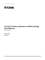
D-Link 1U 4-bay rackmount unified storage
User Manual
DNS-1560-04
Version 1.00
April 2014
Copyright@2014 D-Link System, Inc. All Rights Reserved.
1
D-Link Document – User Manual
Copyright
Copyright@2014, D-Link Corporation, Inc. All rights reserved.
Trademarks
All products and trade names used in this manual are trademarks or registered trademarks of their respective
companies.
Login information
User name: admin
Password: 1234
Copyright@2014 D-Link System, Inc. All Rights Reserved.
2
D-Link Document – User Manual
Preface
About this manual
This manual is the introduction of a D-Link unified storage system and it aims to help users know
the operations of the disk array system easily. Information contained in this manual has been
reviewed for accuracy, but not for product warranty because of the various environments / OS /
settings. Information and specification will be changed without further notice.
Before reading this manual, it is assumed that you are familiar with computer skills such as
hardware, storage concepts and network technology. It is also assumed that you have a basic
knowledge of Redundant Array of Independent Disks (RAID), Storage Area Network (SAN),
Network-Attached Storage (NAS), Internet SCSI (iSCSI), Serial-attached SCSI (SAS), Serial ATA
(SATA), technology.
CAUTION:
Do not attempt to service, change, disassemble or upgrade the equipment’s
components by yourself. Doing so may violate your warranty and expose you to
electric shock. Refer all servicing to authorized service personnel. Please always
follow the instructions in this user manual.
Tips and Cautions
This manual uses the following symbols to draw attention to important safety and operational
information.
Symbol
Meaning
TIP
Description
Tips provide helpful information, guidelines, or suggestions for
performing tasks more effectively.
CAUTION
Cautions indicate that failure to take a specified action could
result in damage to the software or hardware.
Copyright@2014 D-Link System, Inc. All Rights Reserved.
3
D-Link Document – User Manual
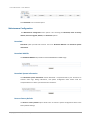
Conventions
The following table describes the typographic conventions used in this manual.
Conventions
Bold
<Italic>
[ ] square
brackets
{ } braces
| vertical bar
/ Slash
underline
Description
Indicates text on a window, other than the window title, including menus,
menu options, buttons, fields, and labels.
Example: Click OK button.
Indicates a variable, which is a placeholder for actual text provided by the
user or system.
Example: copy <source-file> <target-file>.
Indicates optional values.
Example: [ a | b ] indicates that you can choose a, b, or nothing.
Indicates required or expected values.
Example: { a | b } indicates that you must choose either a or b.
Indicates that you have a choice between two or more options or
arguments.
Indicates all options or arguments.
Indicates the default value.
Example: [ a | b ]
FCC and CE statements
FCC statement
This device has been shown to be in compliance with and was tested in accordance with the
measurement procedures specified in the Standards and Specifications listed below and as
indicated in the measurement report number: xxxxxxxx-F
Technical Standard:
FCC Part 15 Class A (Verification)
IC ICES-003
CE statement
This device has been shown to be in compliance with and was tested in accordance with the
measurement procedures specified in the Standards and Specifications listed below and as
indicated in the measurement report number: xxxxxxxx-E
Technical Standard:
EMC DIRECTIVE 2004/108/EC
(EN55022 / EN55024)
UL statement
Rack Mount Instructions - The following or similar rack-mount instructions are included with the
installation instructions:
Copyright@2014 D-Link System, Inc. All Rights Reserved.
4
D-Link Document – User Manual
1.
Elevated Operating Ambient - If installed in a closed or multi-unit rack assembly, the
operating ambient temperature of the rack environment may be greater than room ambient.
Therefore, consideration should be given to installing the equipment in an environment
compatible with the maximum ambient temperature (Tma) specified by the manufacturer.
2.
Reduced Air Flow - Installation of the equipment in a rack should be such that the amount of
air flow required for safe operation of the equipment is not compromised.
3.
Mechanical Loading - Mounting of the equipment in the rack should be such that a
hazardous condition is not achieved due to uneven mechanical loading.
4.
Circuit Overloading - Consideration should be given to the connection of the equipment to
the supply circuit and the effect that overloading of the circuits might have on overcurrent
protection and supply wiring. Appropriate consideration of equipment nameplate ratings
should be used when addressing this concern.
5.
Reliable Grounding - Reliable grounding of rack-mounted equipment should be maintained.
Particular attention should be given to supply connections other than direct connections to
the branch circuit (e.g. use of power strips).
CAUTION:
The main purpose of the handles is for rack mount use only. Do not use the
handles to carry or transport the systems.
The ITE is not intended to be installed and used in a home, school or public area accessible to the
general population, and the thumbscrews should be tightened with a tool after both initial
installation and subsequent access to the panel.
Warning: Remove all power supply cords before service
This equipment intended for installation in restricted access location.
Access can only be gained by SERVICE PERSONS or by USERS who have been instructed
about the reasons for the restrictions applied to the location and about any precautions that
shall be taken.
Access is through the use of a TOOL or lock and key, or other means of security, and is
controlled by the authority responsible for the location.
CAUTION: (English)
Risk of explosion if battery is replaced by incorrect type. Please replace the
same or equivalent type battery use and dispose of used batteries according to
the instructions.
Copyright@2014 D-Link System, Inc. All Rights Reserved.
5
D-Link Document – User Manual
ATTENTION: (French)
IL Y A RISQUE D'EXPLOSION SI LA BATTERIE EST REMPLACÉE PAR UNE BATTERIE
DE TYPE INCORRECT. METTRE AU REBUT LES BATTERIES USAGÉES
CONFORMÉMENT AUX INSTRUCTIONS.
VORSICHT: (German)
Explosionsgefahr bei unsachgemaßem Austausch der Batterie. Entsorgung
gebrauchter Batterien nach Anleitung.
ADVERTENCIA: (Spanish)
Las baterías pueden explotar si no se manipulan de forma apropiada. No
desmonte ni tire las baterías al fuego. Siga las normativas locales al desechar las
baterías agotadas.
警告: (Simplified Chinese)
本电池如果更换不正确会有爆炸的危险,请依制造商说明处理用过之电
池。
Copyright@2014 D-Link System, Inc. All Rights Reserved.
6
D-Link Document – User Manual
Contents
Chapter 0
PREFACE ............................................................................................................................................... 3
ABOUT THIS MANUAL ....................................................................................................................................... 3
TIPS AND CAUTIONS ......................................................................................................................................... 3
CONVENTIONS................................................................................................................................................. 4
FCC AND CE STATEMENTS ................................................................................................................................. 4
Chapter 1
OVERVIEW ..........................................................................................................................................11
PRODUCT OVERVIEW ...................................................................................................................................... 11
Package Contents .............................................................................................................................. 11
HARDWARE .................................................................................................................................................. 11
Front View ......................................................................................................................................... 12
Disk Drive Assembly .......................................................................................................................... 12
Rear View .......................................................................................................................................... 13
RAID CONCEPTS ........................................................................................................................................... 13
RAID Levels ........................................................................................................................................ 13
NAS CONCEPTS............................................................................................................................................. 14
ISCSI CONCEPTS ............................................................................................................................................ 15
Chapter 2
INSTALLATION .....................................................................................................................................16
INSTALLATION OVERVIEW ................................................................................................................................ 16
Drive Slot Numbering ........................................................................................................................ 16
System Installation and Deployment ................................................................................................ 16
POWER ON / OFF ......................................................................................................................................... 17
Power on the System ........................................................................................................................ 17
Power off the System ........................................................................................................................ 17
Chapter 3
QUICK SETUP.......................................................................................................................................18
MANAGEMENT INTERFACES ............................................................................................................................. 18
Web UI .............................................................................................................................................. 18
HOW TO USE THE GUIDED CONFIGURATIONS ...................................................................................................... 21
Setup Wizard Tool ............................................................................................................................. 21
Chapter 4
BASIC CONFIGURATION ......................................................................................................................23
INTERFACE HIERARCHY .................................................................................................................................... 23
DASHBOARD ................................................................................................................................................. 23
MONITOR..................................................................................................................................................... 24
Copyright@2014 D-Link System, Inc. All Rights Reserved.
7
D-Link Document – User Manual
S.M.A.R.T. .......................................................................................................................................... 24
Physical disk ...................................................................................................................................... 25
Snapshot ........................................................................................................................................... 26
Hardware monitor ............................................................................................................................ 27
Event log ........................................................................................................................................... 27
UPS .................................................................................................................................................... 28
Connection ........................................................................................................................................ 28
SYSTEM CONFIGURATION ................................................................................................................................ 29
System ............................................................................................................................................... 29
Time .................................................................................................................................................. 30
Account ............................................................................................................................................. 30
Mail Setting ....................................................................................................................................... 35
Messenger......................................................................................................................................... 35
SNMP ................................................................................................................................................ 36
System Log Server ............................................................................................................................. 36
NETWORK CONFIGURATION ............................................................................................................................. 37
Network Setting ................................................................................................................................ 37
DNS Setting ....................................................................................................................................... 39
STORAGE CONFIGURATION .............................................................................................................................. 40
Physical Disk ...................................................................................................................................... 40
Pool ................................................................................................................................................... 42
ZFS ..................................................................................................................................................... 45
Thin provisioning ............................................................................................................................... 47
Compression ..................................................................................................................................... 48
Share ................................................................................................................................................. 49
Explorer ............................................................................................................................................. 50
Shares................................................................................................................................................ 54
LUN.................................................................................................................................................... 55
Snapshot ........................................................................................................................................... 56
Snapshot Schedule ............................................................................................................................ 57
APPLICATION CONFIGURATION ......................................................................................................................... 57
Directory Services ............................................................................................................................. 58
CIFS Service ....................................................................................................................................... 60
NFS Service ........................................................................................................................................ 60
AFP Service ........................................................................................................................................ 61
FTP Service ........................................................................................................................................ 61
WebDAV Service ............................................................................................................................... 62
iSCSI ................................................................................................................................................... 62
Copyright@2014 D-Link System, Inc. All Rights Reserved.
8
D-Link Document – User Manual
iSCSI Entity ........................................................................................................................................ 63
iSCSI Node ......................................................................................................................................... 63
Backup............................................................................................................................................... 64
Replication ........................................................................................................................................ 64
Amazon S3 ........................................................................................................................................ 65
AntiVirus ........................................................................................................................................... 66
AntiVirus Service ............................................................................................................................... 67
AntiVirus Scan Filter .......................................................................................................................... 67
AntiVirus Task ................................................................................................................................... 67
AntiVirus Update ............................................................................................................................... 68
AntiVirus Report................................................................................................................................ 68
MAINTENANCE CONFIGURATION....................................................................................................................... 69
Download .......................................................................................................................................... 69
Download MIB File ............................................................................................................................ 69
Download System Information ......................................................................................................... 69
Reset to Factory Default ................................................................................................................... 69
Firmware Upgrade ............................................................................................................................ 70
Firmware Upgrade via USB ............................................................................................................... 70
Reboot............................................................................................................................................... 71
Shutdown .......................................................................................................................................... 71
Chapter 5
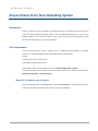
ACCESS SHARES FROM YOUR OPERATING SYSTEM .............................................................................72
INTRODUCTION.............................................................................................................................................. 72
CIFS AND WINDOWS ..................................................................................................................................... 72
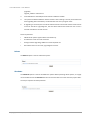
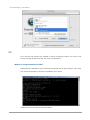
Method 1: The Address Input in Explorer ......................................................................................... 72
Method 2: The Command Line Input from Start Button................................................................... 73
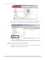
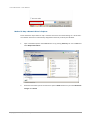
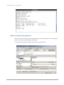
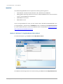
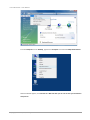
Method 3: Map a Network Drive in Explorer .................................................................................... 74
NFS AND LINUX............................................................................................................................................. 75
Redhat Linux 5 .................................................................................................................................. 75
Redhat Linux 6 .................................................................................................................................. 76
Open Solaris 10/11............................................................................................................................ 76
NFS AND VSHPERE5....................................................................................................................................... 76
AFP AND MAC OS X ...................................................................................................................................... 77
Apple Time Machine Support ........................................................................................................... 78
FTP ............................................................................................................................................................ 79
Method 1: Using Command Line Shell .............................................................................................. 79
Method 2: Using FTP Client Application ........................................................................................... 80
WEBDAV .................................................................................................................................................... 81
Copyright@2014 D-Link System, Inc. All Rights Reserved.
9
D-Link Document – User Manual
Method 1: Windows 7 Using Map Network Drive Wizard ................................................................ 81
rd
Method 2: Using 3 Party WebDAV Client Appplication .................................................................. 85
Chapter 6
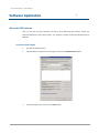
SOFTWARE APPLICATION ....................................................................................................................86
MICROSOFT ISCSI INITIATOR............................................................................................................................ 86
Connect to iSCSI Target ..................................................................................................................... 86
Disconnect ........................................................................................................................................ 87
Chapter 7
ADVANCED OPERATIONS ....................................................................................................................88
TERMINAL OPERATIONS .................................................................................................................................. 88
Serial Console .................................................................................................................................... 88
Secure Shell Remote Access.............................................................................................................. 88
Console UI ......................................................................................................................................... 89
Chapter 8
GLOSSARY AND ACRONYM LIST ..........................................................................................................91
Chapter 9
INDEX ..................................................................................................................................................93
Copyright@2014 D-Link System, Inc. All Rights Reserved.
10
D-Link Document – User Manual
Overview
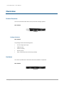
Product Overview
This user manual describes how to set up and use the storage systems.
DNS-1560-04:
1U4bays
Package Contents
DNS-1560-04:
The package contains the following items:
D-Link storage system (x1)
HDD trays (x4)
Power cords (x2)
Rail kit (x1 set)
Keys, screws for drives and rail kit (x1 packet)
Hardware
This section provides basic information about the hardware components.
DNS-1560-04:
(1U4bays)
Copyright@2014 D-Link System, Inc. All Rights Reserved.
11
D-Link Document – User Manual
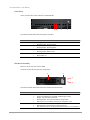
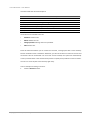
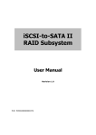
Front View
There are three LEDs and one button on DNS-1560-04
1 2
3
4
This table provides details about the button and LEDs.
Number
1
2
3
4
Description
LAN1(Management port) LED:
Blinking amber: Accessing data.
LAN2 LED:
Blinking amber: Accessing data.
Status LED:
Blinking amber: System error.
Power button.
Blue: Power on.
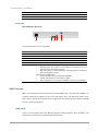
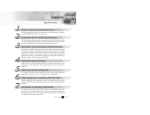
Disk Drive Assembly
Remove a drive tray. Then install a HDD.
The front of each disk tray has four components:
3
4
1
2
This table provides details about the front components of a disk tray.
Number
1
2
Description
Status LED:
Green: The hard drive is inserted and working normally.
Amber: The hard drive has failed.
Blinking amber: The hard drive data is being rebuilt.
Off: There is no hard drive in the tray or the power is off.
Access LED:
Blinking green: The hard drive is being accessed.
Off: The hard drive is not being accessed or there is no hard drive in
Copyright@2014 D-Link System, Inc. All Rights Reserved.
12
D-Link Document – User Manual
the tray.
Tray removal handle.
Latch to release the tray and tray handle.
3
4
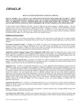
Rear View
DNS-1560-04 (2 x GbE ports):
2 3 4
1
5
This table describes the rear components.
Number
1
2
3
4
5
LED
Description
Power Connector.
LAN1 (GbE) and management port.
LAN2 (GbE) port.
USB ports.
VGA port.
GbE Activity LED:
Blinking green: The system is transmitting or receiving to/from an
Ethernet device through the 1G port.
Off: The system is not transmitting or receiving to/from an Ethernet
device through the 1G port.
GbE Connection/Speed LED:
Green: The GbE port is connected at 100 Mbps.
Yellow: The GbE port is connected at 1 Gbps.
Off: The GbE port is connected at 10 Mbps or there is no connection.
RAID Concepts
RAID is the abbreviation of Redundant Array of Independent Disks. The basic idea of RAID is to
combine multiple drives together to form one large logical drive. This RAID drive obtains more
performance, capacity and reliability than a single drive. The operating system detects the RAID
drive as a single storage device.
RAID Levels
There are various RAID levels with different degrees of data protection, data availability, and
performance. A description of supported RAID levels follow:
Copyright@2014 D-Link System, Inc. All Rights Reserved.
13
D-Link Document – User Manual
Type
RAID 0
RAID 1
RAID 5
RAID 6
RAID 50
RAID 60
Description
Disk striping.
Disk mirroring over two disks.
Striping with interspersed parity over the member disks.
2-dimensional parity protection over the member disks.
Striping over the member RAID 5 volumes.
Striping over the member RAID 6 volumes.
Min. No. of Drives
1
2
3
4
6
8
NAS Concepts
NAS (Network-Attached Storage) is file-level computer data storage connected to a computer
network providing data access to heterogeneous clients. NAS uses file-based protocols such as NFS
(popular on UNIX systems), SMB/CIFS (Server Message Block/Common Internet File System) (used
with MS Windows systems), or AFP (used with Apple Macintosh computers). NAS units rarely limit
clients to a single protocol.
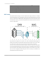
NAS provides both storage and a file system. This is often contrasted with SAN (Storage Area
Network), which provides only block-based storage and leaves file system concerns on the "client"
side. SAN protocols are SCSI, Fibre Channel, iSCSI, ATA over Ethernet (AoE), or HyperSCSI.
One way to loosely conceptualize the difference between a NAS and a SAN is that a NAS appears
to the client OS (operating system) as a file server (the client can map network drives to shares on
that server) whereas a disk available through a SAN still appears to the client OS as a disk, visible in
disk and volume management utilities (along with client's local disks), and available to be
formatted with a file system and mounted.
Copyright@2014 D-Link System, Inc. All Rights Reserved.
14
D-Link Document – User Manual
iSCSI Concepts
iSCSI (Internet SCSI) is a protocol which encapsulates SCSI (Small Computer System Interface)
commands and data in TCP/IP packets for linking storage devices with servers over common IP
infrastructures. iSCSI provides high performance SANs over standard IP networks like LAN, WAN or
the Internet.
IP SANs are true SANs (Storage Area Networks) which allow several servers to attach to an infinite
number of storage volumes by using iSCSI over TCP/IP networks. IP SANs can scale the storage
capacity with any type and brand of storage system. In addition, it can be used by any type of
network (Ethernet, Fast Ethernet, Gigabit Ethernet, and 10 Gigabit Ethernet) and combination of
operating systems (Microsoft Windows, Linux, Solaris, Mac, etc.) within the SAN network. IP-SANs
also include mechanisms for security, data replication, multi-path and high availability.
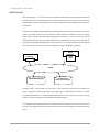
Host 2
(initiator)
iSCSI
HBA
Host 1
(initiator)
NIC
IP SAN
iSCSI device 1 (target)
iSCSI device 2 (target)
Storage protocol, such as iSCSI, has “two ends” in the connection. These ends are initiator and
target. In iSCSI, we call them iSCSI initiator and iSCSI target. The iSCSI initiator requests or initiates
any iSCSI communication. It requests all SCSI operations like read or write. An initiator is usually
located on the host side (either an iSCSI HBA or iSCSI SW initiator).
The target is the storage device itself or an appliance which controls and serves volumes or virtual
volumes. The target is the device which performs SCSI command or bridge to an attached storage
device.
Copyright@2014 D-Link System, Inc. All Rights Reserved.
15
D-Link Document – User Manual
Installation
Installation Overview
Before starting, prepare the following items:
A management computer with a Gigabit Ethernet NIC (recommend) on the same network.
Connection cables:
。
CAT 5e, or CAT 6 (recommend) network cables.
Prepare a storage system configuration plan by the network administrator. The plan should
include network information for all network ports. If using static IP addresses, please
prepare a list of the static IP addresses, the subnet mask, and the default gateway.
Switches
。
: Gigabit switches (recommended). Or Gigabit switches with VLAN / LCAP / Trunking
(optional).
CHAP security information, including CHAP username and password (optional).
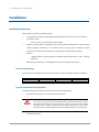
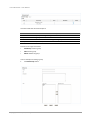
Drive Slot Numbering
The drives can be installed into any slot in the enclosure. Slot numbering is reflected in Web UI.
Slot 1
Slot 2
Slot 3
Slot 4
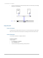
System Installation and Deployment
Using the following instructions to install and deploy the storage system.
Install the Rail Kit onto the unit and insert it into the rack.
CAUTION:
The system is very heavy. It’s recommend that a mechanical lifter or at least
two persons be used to raise and align the system to prevent injury during
installation. Use care when inserting or removing a system into or out of a rack
to prevent the accidental tipping or the rack causing damage or personal injury.
Install the disk drives.
Copyright@2014 D-Link System, Inc. All Rights Reserved.
16
D-Link Document – User Manual
Connect the management port cable and data port cables on the network plan, the topology
examples are on the following.
Power ON / OFF
Power on the System
The power button is located at the front of the panel. To turn the system ON, press power button.
After you turn the power ON, the system performs a booting process which takes a few minutes.
Power off the System
It can shutdown via Web UI or management software.
Shutdown using Web UI
Using the Web UI:
Select Maintenance -> Shutdown.
Click the Shutdown button.
The power LED will display blue blinking, and then power off.
Copyright@2014 D-Link System, Inc. All Rights Reserved.
17
D-Link Document – User Manual
Quick Setup
Management Interfaces
There are several management methods to manage the storage system, described below.
Web UI
For remote management, the unified storage system uses a web graphic user interface for
operation. It supports most common web browsers. Be sure to connect the LAN cable to the
management port of the system.
The web UI can be accessed via every network interface, but D-Link still defines a management
port. The default IP of the management port setting is DHCP; check the LCM to find the IP address.
If your network does not have DHCP server, you will need to configure a static IP address.
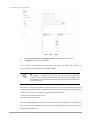
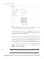
Enter the IP address into your browser to display the authentication screen.
http://<IP Address> (e.g.: http://192.168.10.50)
Copyright@2014 D-Link System, Inc. All Rights Reserved.
18
D-Link Document – User Manual
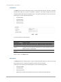
To access the Web UI, you have to enter a user name and password. The initial defaults for
administrator login are:
User name: admin
Password: 1234
When the password has been verified, the home page is displayed.
Copyright@2014 D-Link System, Inc. All Rights Reserved.
19
D-Link Document – User Manual
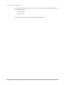
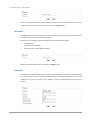
Logout Button
Menu Bar
Options
Display and
Operation Area
Choose the functions from the Menu Bar on the top side of the window to make any configuration
changes.
Copyright@2014 D-Link System, Inc. All Rights Reserved.
20
D-Link Document – User Manual
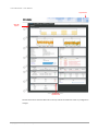
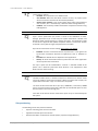
How to Use the Guided Configurations
To help users get started quickly, a guided configuration tool is available in the Web UI. The Setup
wizard guides you an easy way to create a volume. If you are an advanced user, you can skip this
step.
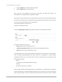
Setup Wizard Tool
This tool guides you through the process of setting up basic array information, configuring network
settings, and the creation of a pool on the storage system. Please make sure that the system has
some free hard drives installed on it. The following is the procedure.
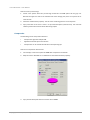
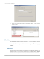
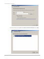
1.
Click Configuration / Setup wizard.
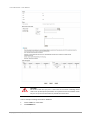
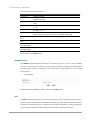
2.
Enter a System name and set up the Time and date if necessary. Choose the Time zone and
RAID level of pool, then click the Apply button to proceed.
Copyright@2014 D-Link System, Inc. All Rights Reserved.
21
D-Link Document – User Manual
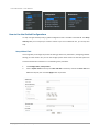
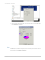
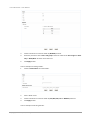
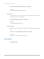
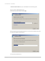
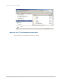
3.
The file systems and volumes are created and named by the system automatically. The
system is also created for sharing usage. It is now available to use.
Copyright@2014 D-Link System, Inc. All Rights Reserved.
22
D-Link Document – User Manual
Basic Configuration
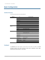
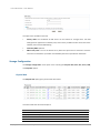
Interface Hierarchy
This table describes the hierarchy of the Web GUI.
Menu Bar
Dashboard
Monitor
Monitor
Configuration
Maintenance
L1
Disk throughput
Network flow (Mb)
Device information
System status
Temperature
Power supply
Cooling
Service status
Event log
Pool status
S.M.A.R.T
Physical disk
Snapshot
Hardware monitor
Event log
UPS
Connection
Setup wizard
System Configuration
Network
Configuration
Storage
Configuration
Application
Configuration
Download
Reset to Factory
Default
Firmware Upgrade
Reboot
Shutdown
L2, Button or Menu
Directory services / CIFS / NFS / ARP / FTP / WebDAV
Filter
Clear / Download / Filter
System / Time / Account / Mail Setting / Messenger / SNMP /
System Log Server / UPS
Network Settings / DNS Settings
Physical Disk / Pool / ZFS / Share / LUN / SnapShot
Directory Servers / CIFS / NFS / AFP / FTP / WebDAV / ISCSI /
Backup / Antivirus
Download
Reset device
Upgrade
Reboot
Shutdown
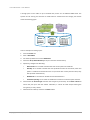
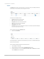
Dashboard
The Dashboard menu option displays a whole picture of the system. The tables include Disk
throughput, Network flow, Device information, System status, Temperature, Power supply,
Cooling, Service status, Event log, and Pool status.
Copyright@2014 D-Link System, Inc. All Rights Reserved.
23
D-Link Document – User Manual
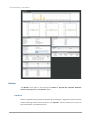
Monitor
The Monitor menu option is for accessing the S.M.A.R.T., Physical disk, Snapshot, Hardware
monitor, Event log, UPS, and Connection options.
S.M.A.R.T.
S.M.A.R.T. (Self-Monitoring Analysis and Reporting Technology) is a diagnostic tool for hard drives
to deliver warning of drive failures in advance. The S.M.A.R.T. option provides users a chance to
take actions before a possible drive failure.
Copyright@2014 D-Link System, Inc. All Rights Reserved.
24
D-Link Document – User Manual
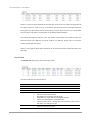
S.M.A.R.T. measures many attributes of the hard drive all the time and inspects the properties of
hard drives which are close to be out of tolerance. The advanced notice of possible hard drive
failure gives users precautions to back up hard drive or replace the hard drive. This is much better
than hard drive crash when it is writing data or rebuilding a failed hard drive.
The numbers displayed are real-time value. The number in parenthesis is the threshold value. The
threshold values from different hard drive vendors are different; please refer to hard drive
vendors’ specification for details.
S.M.A.R.T. only supports SATA drives. SAS drives do not have this function and will show N/A in the
web page.
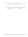
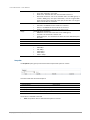
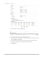
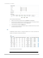
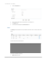
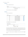
Physical disk
The Physical disk option gives you the hard drive status.
This table shows the column descriptions.
Column Name
Slot No.
Size (GB)
Pool Name
Status
Health
Description
The position of a hard drive.
Capacity of hard drive.
Pool name.
The status of the hard drive:
Online: the hard drive is online.
Rebuilding: the hard drive is being rebuilt.
Degraded: one of the RAID set is at degraded mode.
Failed: one of the RAID set is at failed mode.
Importing: the system is loading data from the disks, which means
the pool is not ready for use yet.
The health of the hard drive:
Good: the hard drive is good.
Copyright@2014 D-Link System, Inc. All Rights Reserved.
25
D-Link Document – User Manual
Failed: the hard drive is failed.
Error alert: S.M.A.R.T. error alert.
Read errors: the hard drive has unrecoverable read errors.
Reserved: the disk is one of the member disks of a RAID group. It
contains RAID group and pool information, but the original RAID
group and pool can’t be found. Either you put this disk in its original
slot or set this disk as a free disk.
The SMART of the hard drive:
Unknown: the SMART of the hard drive is unknown.
NoError: the SMART of the hard drive has no errors.
HasError: the SMART of the hard drive has an error.
The usage of the hard drive:
RAID disk: This hard drive has been set to a RAID group.
Free disk: This hard drive is free for use.
Dedicated spare: This hard drive has been set as the dedicated spare
of a pool.
HDD or SSD.
Hard drive vendor.
Hard drive serial number.
Hard drive rate:
SAS 6Gb/s.
SAS 3Gb/s.
SATA 6Gb/s.
SATA 3Gb/s.
SATA 1.5Gb/s.
SMARTCTL
Usage
SSD
Vendor
Serial
Rate
Snapshot
The Snapshot option gives you the status of the snapshot file system or volume.
This table shows the column descriptions.
Column Name
Name
Used (MB)
Refer (GB)
Created time
Description
The snapshot name.
The amount of snapshot space that has been used.
The refer capacity of the file system or volume.
The time that the snapshot is created.
The function is available in this tab:
Filter: Drop down menu to select the file system or volume.
Copyright@2014 D-Link System, Inc. All Rights Reserved.
26
D-Link Document – User Manual
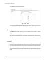
Hardware monitor
The Hardware monitor option provides the status of system voltage, temperature, power supply,
and cooling. The following example shows voltage.
This table shows the column descriptions.
Column Name
Item
Value
Status
Description
The item name.
The value of the item and its criteria.
OK or Fail.
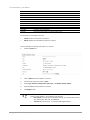
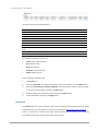
Event log
The Event log option provides a log for event messages. In filter the section, check INFO,
WARNING, or ERROR to display these particular events.
The options are available on this tab:
Clear: Click Clear button to clear all event logs.
Download: Click Download button to save the whole event log as a text file with file name
“LOG-SystemName-Date-Time.log”.
The event log is displayed in reverse order which means the latest event log is on the first / top
page. When the UserHome directory exists, the system will store event log content in the storage
pool where the UserHome directory belongs. Deleting the UserHome pool will result in deleting
Copyright@2014 D-Link System, Inc. All Rights Reserved.
27
D-Link Document – User Manual
event log content. Re-assigning the UserHome directory to a different storage pool will wipe the
event log content out as well.
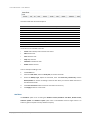
UPS
The UPS option provides the status of the UPS (Uninterruptible Power Supply).
This table shows the available options and their descriptions.
Column Name
UPS Type
Shutdown battery
level (%)
Shutdown delay
(s)
Shutdown UPS
Battery level (%)
Description
UPS Type:
None: No UPS or other vendors.
Smart-UPS: APC UPS.
When below the setting level, the system will shutdown. “0” is disabled
UPS.
If power failure occurs and system power cannot recover after the time
setting, the system will shutdown. “0” is disabled the function.
The status of shutdown UPS:
UPS Type:
ON: When power is gone, UPS will shutdown by itself after the
system shuts down successfully. After the power comes back, UPS
will start working and notify system to boot up.
OFF: Will not.
Current power percentage of battery level.
The system will shutdown if either Shutdown battery level (%) or Shutdown delay (s) reaches the
condition. User should set these values carefully.
Connection
The Connection option displays all the connection information for the system.
Copyright@2014 D-Link System, Inc. All Rights Reserved.
28
D-Link Document – User Manual
This table shows the available options and their descriptions.
Column Name
Protocol
User
Client
Server
Description
The protocol type of the connection.
The connection user.
The client information of the connection.
The server information of the connection.
System Configuration
The System configuration menu option is for accessing the System, Time, Account, Mail setting,
Messenger, SNMP, System log server, and UPS options.
System
The System option is used to setup the system name, system indication, buzzer and auto
shutdown. The default system name is composed of the model name and the serial number of this
system.
The options that are available in this tab:
System name: To change the System name, highlight the old name and type in a new one.
Buzzer: If the buzzer is enabled, the system will make a sound like a bee buzzing when on
abnormal status.
Auto shutdown: Enable this to let the system shutdown automatically when the voltage or
temperature is out of the normal range. For better data protection, it is recommended to
check Auto Shutdown.
When it is done, click the Apply button.
Copyright@2014 D-Link System, Inc. All Rights Reserved.
29
D-Link Document – User Manual
Time
The Time option is used to setup the system time and NTP (Network Time Protocol) server setting.
The options available in this tab are:
Time and Date Setup: Changes the current date, time or time server. Enter the IP address to
synchronize the time from a time server.
Time Zone Setup: Changes time zone settings.
When it is done, click Apply button.
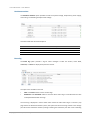
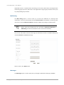
Account
The Account option is used to setup users and groups in the system. It is for accessing the User
account, Group account, and Import/Export account option tabs.
The User account tab provides a function to manage local user accounts such as add, delete, edit,
change password or view the status of the users. Local user accounts and domain user accounts
are displayed separately by selecting the drop down list.
Domain user accounts are only for display purpose. You cannot edit domain account or change the
password of domain account.
Copyright@2014 D-Link System, Inc. All Rights Reserved.
30
D-Link Document – User Manual
This table shows the column descriptions.
Column Name
UID
User name
Group
Quota (GB)
Used (%)
Email
Description
Description
The user ID.
The account name.
The user belongs to the groups.
User quota space.
The percentage of the quota usage.
User’s email.
User’s description.
The functions are available in this tab:
Add User: Create a user.
Delete: Delete the user.
Change password: Change the user’s password.
Edit: Edit the user.
Please be aware that before you can create local accounts, a storage pool with a home directory
function enabled must be created first. Otherwise, you will not be able to create local account and
all functions will be unselectable. For each local account created, the system will automatically
create a personal folder in the home directory with the capacity limit specified in account creation.
The user can access his/her home directory right away.
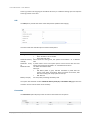
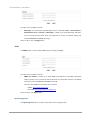
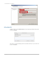
Take an example of creating an account.
1.
Click the Add User button.
Copyright@2014 D-Link System, Inc. All Rights Reserved.
31
D-Link Document – User Manual
2.
Enter the Name, Password, and Retype password. The other fields are optional.
3.
Click Apply button to create an account.
UID is open for user assignment. If UID input is left blank, the system will assign an ID
automatically. User-assigned ID has a range 1000 ~ 60000.
TIP:
The password is required to be at least 12 and up to 16 alphanumeric
characters. This is because of UnifiedAUTH mechanism that will integrate with
iSCSI CHAP account. iSCSI CHAP account requires that the password needs to be
12 to 16 characters.
If the system is using Active Directory or LDAP as directory service, you may see the domain users
as below. Please be aware that no modification (add, delete, edit, change password) can be made
to domain users. This can only be done on the AD server or LDAP server.
The syntax to represent a domain user is :
<domain name>+<user account>
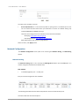
The menu Group account tab provides the function to manage local groups such as add, delete,
edit, or view the status of the groups. Local groups and domain groups are displayed separately by
selecting the drop down list.
Copyright@2014 D-Link System, Inc. All Rights Reserved.
32
D-Link Document – User Manual
This table shows the column descriptions.
Column Name
GID
Group name
#User
Description
Description
Group ID (user assigned range 1000 ~ 60000).
The group name.
The number of users that belong to this group.
Group’s description.
Functions in the right click menu:
Add Group: Create a group.
Edit: Edit the group.
Delete: Delete the group.
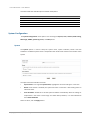
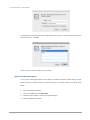
Take an example of creating a group.
1.
Click Add Group button.
Copyright@2014 D-Link System, Inc. All Rights Reserved.
33
D-Link Document – User Manual
2.
Enter the Name field. The other fields are optional.
3.
Click the Apply button to create a group.
GID is open for user assignment. If GID input is left blank, the system will assign an ID
automatically. User-assigned ID has a range 1000 ~ 60000.
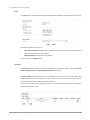
If the system is using Active Directory or LDAP as directory service, you may see the domain groups
as below. Please be aware that no modification (add, delete, edit) can be made to domain groups.
This can only be done on the AD server or LDAP server.
The syntax to represent a domain user is:
<Domain name>+<group name>
The menu Import/Export account tab provides the function to import/export accounts.
The options available on this tab are:
Export: Export all users and groups to a file.
Overwrite duplicated account: Check this to overwrite duplicated accounts.
Import: Import all users and groups from a file.
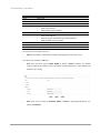
The import/export file is a pure text file with the following format. Each attribute is separated by a
colon. For group account between two colons, each user is separated by a comma. Before
importing account file, you may create several accounts and export the account file first to get
familiar with the format.
[Users]
user name:user password:quota:UID:email:desc
[Groups]
group name:user1,user2...:GID:desc
Please be aware that the actual password will not be exported. In an exported file, the password
will be replaced with a dummy password 1234. When the same account name (case sensitive)
exists during importing, it will not overwrite the existing account information unless “overwrite
Copyright@2014 D-Link System, Inc. All Rights Reserved.
34
D-Link Document – User Manual
duplicated account” is checked. When overwriting a user account, UID remains unchanged. When
overwriting a group account, GID remains unchanged and the original group members remain plus
any newly added group members.
Mail Setting
The Mail setting option is used to enter up to three mail addresses for receiving event
notifications. Fill in the necessary fields and click Send test mail to test whether it is working. Some
mail servers check the Mail-from address and need the SMTP relay setting for authentication.
TIP:
Please make sure the DNS server IP is well-setup in Network configuration ->
DNS Setting. So the event notification mails can be sent successfully.
You can also select which levels of event logs you would like to receive. The default setting only
includes WARNING and ERROR event logs.
When it is done, click Apply button.
Messenger
The Messenger option is used to setup pop-up messages via Windows messenger (not MSN).
Copyright@2014 D-Link System, Inc. All Rights Reserved.
35
D-Link Document – User Manual
The options are available in this tab:
Messenger: You must enable the Messenger service in Windows (Start -> Control Panel ->
Administrative Tools -> Services -> Messenger). It allows up to three Messenger addresses.
You can choose the alert levels which you would like to receive. The default setting only
includes WARNING and ERROR event logs.
When it is done, click the Apply button.
SNMP
The SNMP option is used to setup SNMP traps (for alerting via SNMP).
The options are available in this tab:
SNMP trap address: It allows up to three SNMP trap addresses. The default community
setting is public. You can choose the alert levels which you would like to receive. The default
setting only includes WARNING and ERROR event logs.
There are many SNMP tools available on the internet.
。
SNMPc: http://www.snmpc.com/
。
Net-SNMP: http://net-snmp.sourceforge.net/
When it is done, click Apply button.
System Log Server
The System log server option is used to setup alerts via the syslog protocol.
Copyright@2014 D-Link System, Inc. All Rights Reserved.
36
D-Link Document – User Manual
The options are available in this tab:
Server IP/hostname: Fill in the necessary fields for syslog service. The default port is 514.
You can choose the alert levels which you would like to receive. The default setting only
includes WARNING and ERROR event logs.
There are some syslog server tools available on the internet for Windows.
。
WinSyslog: http://www.winsyslog.com/
。
Kiwi Syslog Daemon: http://www.kiwisyslog.com/
Most UNIX systems have a built-in syslog daemon.
When it is done, click Apply button.
Network Configuration
The Network configuration menu option is for accessing the Network Setting, and DNS Setting
options.
Network Setting
The Network setting option is for accessing the Management network port and LAN ports. It is
used to change the IP addresses of network ports.
DNS-1560-04:
1 x GbE Management port + 1 x GbE port.
Each port must be assigned its own IP address.
The following table describes the relationship with the service and the network ports.
This table shows the column descriptions.
Copyright@2014 D-Link System, Inc. All Rights Reserved.
37
D-Link Document – User Manual
Column Name
Name
Ling
VLAN ID
Protocol
IPV4 Type
IPV4 IP
IPV6 Type
IPv6 IP
Jumbo frame
MAC Address
Description
Port name.
Link up or down.
VLAN number.
Use IPv4 or IPv6.
IPv4 address mode:
Static: static address.
DHCP: DHCP assigned address.
IPv4 address.
IPv6 address mode:
Static: static address.
Auto: RA (router advertisement) calculated address.
DHCP: DHCPv6 assigned address.
IPv6 address.
Jumbo frame size
MAC address
The functions are available in this tab:
Edit: Set IPv4 address, IPv6 address, VLAN ID, Default gateway and Jumbo frame.
The options are available on Edit icon:
IPv4: There are three options: DHCP, BOOTP or specify a Static IP address. The default
setting is DHCP. If the network environment does not have DHCP server, the IP address will
fallback to zero config.
IPv6: There are three options: Automatic, DHCP, or Static for specifying IPv6 address. The
default is Automatic.
Copyright@2014 D-Link System, Inc. All Rights Reserved.
38
D-Link Document – User Manual
VLAN ID: Setup VLAN ID and priority if necessary.
Default gateway: Enable or disable the port as default gateway.
Jumbo frame: Enable or disable jumbo frame on the port.
DNS Setting
The DNS setting option is for accessing the DNS (Domain Name Service) setting. It is used to
change DNS IP addresses.
Copyright@2014 D-Link System, Inc. All Rights Reserved.
39
D-Link Document – User Manual
The options are available on this tab:
Primary DNS: The IP address of DNS server can be entered or changed here. The DNS
settings will be applied to all network ports, which mean you ONLY need to select one of the
network ports and start DNS setting.
Secondary DNS: Optional.
DNS search path: It is a list of domains to try when the system tries to translate a machine
name into an IP address. It provides more flexibility than the simple domain statement.
Storage Configuration
The Storage configuration menu option is for accessing the Physical disk, Pool, ZFS, Share, LUN,
and Snapshot options.
Physical Disk
The Physical disk option gives you the hard drive status.
This table shows the column descriptions.
Column Name
Slot No.
Size (GB)
Pool Name
Status
Description
The position of a hard drive.
Capacity of hard drive.
Pool name.
The status of the hard drive:
Copyright@2014 D-Link System, Inc. All Rights Reserved.
40
D-Link Document – User Manual
Online: the hard drive is online.
Rebuilding: the hard drive is being rebuilt.
Degraded: one of the RAID set is at degraded mode.
Failed: one of the RAID set is at failed mode.
Importing: the system is loading data from the disks, which means
the pool is not ready for use yet.
The health of the hard drive:
Good: the hard drive is good.
Failed: the hard drive has failed.
Error alert: S.M.A.R.T. error alert.
Read errors: the hard drive has unrecoverable read errors.
Reserved: the disk is one of the member disks of a RAID group. It
contains RAID group and pool information, but the original RAID
group and pool can’t be found. Either you put this disk at its original
slot or set this disk as a free disk.
The SMART of the hard drive:
Unknown: the SMART of the hard drive is unknown.
NoError: the SMART of the hard drive has no error.
HasError: the SMART of the hard drive has error.
The usage of the hard drive:
RAID disk: This hard drive has been set to a RAID group.
Free disk: This hard drive is free for use.
Dedicated spare: This hard drive has been set as dedicated spare of
a pool.
HDD or SSD.
Hard drive vendor.
Hard drive serial number.
Hard drive rate:
SAS 6Gb/s.
SAS 3Gb/s.
SATA 6Gb/s.
SATA 3Gb/s.
SATA 1.5Gb/s.
Hard drive write cache is enabled or disabled. The default value is Enabled.
HDD auto spindown to save power. The default value is Disabled.
This feature makes data be loaded to disk’s buffer in advance for further
use. The default value is Enabled.
Newer SATA and most SCSI disks can queue multiple commands and
handle one by one. The default value is Enabled.
Health
SMARTCTL
Usage
SSD
Vendor
Serial
Rate
Write cache
Standby
Readahead
Command
queuing
The functions are available in this tab:
SMARTCTL self-test running: Active or inactive SMART self-test.
Download SMARTCTL log: Download SMART self-test log.
Set free disk: Make the hard drive free for use.
Disk replace: Replace the hard drive of the pool to another free hard drive.
Copyright@2014 D-Link System, Inc. All Rights Reserved.
41
D-Link Document – User Manual
Pool
The Pool option provides various functions to manage storage pool such as create, expand, and set
home directory, delete, or view the status of the pools.
This table shows the column descriptions.
Column Name
Name
Total (GB)
Used (GB)
Free (GB)
Capacity
Status
Home
RAID set slot
Spare slot
Read cache slot
Write cache slot
Description
Pool name.
Total capacity of this pool.
Used capacity of this pool.
Free capacity of this pool.
The percentage or the capacity.
The status of the pool:
Online: the pool is good.
Failed: the pool fails.
Rebuild: the pool is being rebuilt.
The home directory is in the pool or not.
The physical disk slots of the RAID set.
The spare physical disk slot.
The SSD drives that are used as read cache (L2ARC).
The SSD drives that are used as write cache (ZIL).
The functions are available in this tab:
Create: Create a pool.
Import encrypt key: Import the encrypt key file for security. (Not available in U110)
Edit: Edit the pool settings.
Expand: Add more RAID sets to the same pool to expand the capacity.
Scrub: Perform pool scrubbing manually to make sure there is no defect in the hard drive.
Export encrypt key: Export the encrypt key file. (This icon is shown when the pool is enabled
the pool encrypt function.)
Delete: Delete the pool. The pool can be deleted when there is no file system or volume in it.
Copyright@2014 D-Link System, Inc. All Rights Reserved.
42
D-Link Document – User Manual
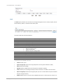
A storage pool can be made of up to 512 RAID sets, which can use different RAID levels. File
systems for file sharing and volumes for iSCSI LUNs are created from the storage pool. Please
check the following graph.
FileSystemFileSystem
FileSystem
FileSystem FileSystem
RAID set 1
RAID 0
RAID set 2
RAID 5
Volume
Volume
Volume
RAID set 3
RAID 6
Pool
Take an example of creating a pool.
1.
Click the Create icon.
2.
Enter a Pool Name.
3.
Use the drop-down list to select a RAID level.
4.
Check the Set up Home Directory if the pool contains home directory.
5.
Optionally, configure the following:
Write Cache: It’s to enable or disable the write cache option of hard drives.
Standby: It’s to enable or disable the auto spindown function of hard drives, when this
option is enabled and hard drives have no I/O access after certain period of time, they
will spin down automatically.
6.
Readahead: It’s to enable or disable the read ahead function.
Command queuing: It’s to enable or disable the hard drives’ command queue function.
Check Enable for Pool encrypt and enter the encrypt key if necessary. Check Auto unlock will
unlock the pool upon the next reboot. Otherwise, it cannot be used except entering the
encrypt key on every reboot.
7.
Select disks from below, and then click Next button.
Copyright@2014 D-Link System, Inc. All Rights Reserved.
43
D-Link Document – User Manual
8.
At the confirmation message, click Apply button.
Take an example of set the disk properties and dedicated spare disk.
1.
Dedicated spare disk is applied to specific storage pool. Make sure you have free hard drives
for this. Click Edit icon in Modify field.
2.
Enable or disable the properties of write cache, standby, readahead, command queuing.
3.
Select the free disk you want to use as dedicated spare disk for this pool.
4.
Click Apply button.
Copyright@2014 D-Link System, Inc. All Rights Reserved.
44
D-Link Document – User Manual
Take an example of expand the pool.
1.
Make sure you have free hard drives for this. Click Expand icon in Modify field.
2.
Pool name can’t be changed since this is to expand the current pool, not creating a new pool.
Select the RAID level and physical disks, and the click Next button.
3.
At the confirmation message, click Apply button.
4.
You may see that the capacity of Pool becomes larger. In the RAID set slot column, it shows
the RAID set members of the pool.
ZFS
The ZFS option provides functions to manage ZFS datasets such as create, edit, delete, take
snapshot, auto snapshot or view the status of the ZFS.
This table shows the column descriptions.
Column Name
Copyright@2014 D-Link System, Inc. All Rights Reserved.
Description
45
D-Link Document – User Manual
Name
Type
Quota (GB)
Reserved (GB)
Used (GB)
Block size
Compress
Sync
Copies
Schedule
Original
The name of the file system or volume.
File system or volume.
The Quota of the file system or volume.
Reserved capacity of the file system or volume.
Used capacity of the file system or volume.
The block size of ZFS.
The status of the compression.
The status of the sync.
The number of the copies. (More explanation in Tip.)
The status of the schedule.
The original file system or volume of the clone.
The functions are available in this tab:
Create: Create a file system or a volume.
Delete: Delete the selected file systems or volumes.
Take an example of creating a file system or a volume.
1.
Click the Create icon.
2.
Enter a Name for the file system or volume.
3.
Use the drop-down list to select a Pool.
4.
Select Type, Property, Compression type, Sync, and Number of Data Copies.
5.
Enter the Size for the file system or volume.
6.
Click Apply button.
TIP:
“Type” has two options – “File system” and “Volume”.
File system: File level access and folder sharing. To use with data services
such as CIFS, NFS, AFP, FTP, and WebDAV.
Volume: Block level access. To use with iSCSI target function.
Copyright@2014 D-Link System, Inc. All Rights Reserved.
46
D-Link Document – User Manual
TIP:
“Compression” options:
Disabled: No compression at all. Default value.
Zero Reclaim: When the data block contains all zeros, no physical space
will be consumed. The block will be marked specifically.
Generic Zero Reclaim: It will reclaim data blocks with special patterns
such as all 0’s, all 1’s. Theoretically, it will have better storage efficiency.
Enabled: This will always enable lossless data compression function using
LZJB algorithm.
TIP:
“Sync” means synchronous I/O, which is similar to the definition of writethrough. Synchronous I/O is that every file system transaction is written and
flushed to stable storage devices by a system call return. The application needs
to wait for the physical data update completion before it could issue another
command. Latency will be longer and performance will suffer.
If you don’t know how to use this setting, please leave it as default.
Disabled: All write commands become asynchronous. It will ignore the
synchronous transaction demands of applications such as database or
NFS.
Standard: The default value. It depends on the applications.
Always: All write commands become synchronous even if the application
issues asynchronous transactions.
The “Sync” option will be unselectable if “volume” is selected instead of file
system. This is because synchronous write function is not supported in iSCSI
block access for the time being.
TIP:
“Number of data copies” in Create File System or Volume UI is used to create
mirroring of data to avoid data corruption. When the original file corrupts, the
system will use the extra “copy” to recover the corrupt file.
The value of two means that when you copy a 10MB file, it will take up 20MB
space. The value of three means that it will take up extra double space to store
the same data in the same storage pool.
Users will not be able to see the actual extra copies. They are controlled by the
file system.
Thin provisioning
The following are the thin provision features:
Dynamic allocating space to store user data.
Applied to both file system and volume.
Remove stranded or reserved-but-unused capacity. Improve storage efficiency.
Copyright@2014 D-Link System, Inc. All Rights Reserved.
47
D-Link Document – User Manual
How to use thin provisioning?
1.
Create a file system with thin provisioning turned ON. The Size option will be grey out.
Because the upper size limit is the available size of the storage pool, there is no quota size or
reserved size.
2.
Check the network drive property. The size is the remaining pool size. So it’s dynamic.
3.
Copy some files to the share. There is no pre-allocated space (reserved size). The used size
reflects just the exact amount of the files being copied.
Compression
The following are the compression features:
Compression algorithm adopts LZJB.
Applied to both file system and volume.
Compression can be turned ON and OFF on the fly during I/O.
How to use compression with shares?
1.
For example, create a file system of 20MB with compression turned ON.
2.
Map the share in Windows as a network drive. And check the drive property.
3.
Copy several bitmap files that are over the size of 20MB.
Copyright@2014 D-Link System, Inc. All Rights Reserved.
48
D-Link Document – User Manual
4.
Check the network drive property again. The actual space taken is less than 20MB, which
means Compression is functioning.
Share
The Share option is provided to manage the permission of the file system and view the status of
each file system. There are Explorer and Shares tabs.
Copyright@2014 D-Link System, Inc. All Rights Reserved.
49
D-Link Document – User Manual
Explorer
The Explorer tab provides a simple file explorer to create, edit, search, and delete the folders of
the file systems. It also browses the whole storage pool structure.
The functions are available in this tab:
Forward: Forward to the previous folder.
Root: Jump to the root of the system.
File system: Enter to the next layer of the folder.
Edit: Edit the share permission of the folder.
Create folder: Create a folder.
Search files: Search the user-specified file in the pool. If it is found, the path will be displayed.
So user can locate the file more easily.
Take an example of entering the UserHome folder.
1.
Click the link of UserHome.
The UserHome folder is created for the home directory of each user. It’s a default folder by the
system and cannot be edited.
Take an example of editing the folder for CIFS, NFS, AFP and FTP.
1.
Click the Edit icon of the folder.
2.
Click the check box to share the folder by CIFS, NFS, AFP, FTP protocols.
3.
If select NFS protocol, it has to set the NFS access control rules. Use Add button to add the
rules and Delete button to delete them.
Copyright@2014 D-Link System, Inc. All Rights Reserved.
50
D-Link Document – User Manual
TIP:
NFS access control rules:
Root squash: Uncheck this to use no_root_squash setting.
Async write: Check this to use asynchronous write function. The
performance will be better than synchronous write.
Read only and Read/Write: Set the read/write permission.
IPv4: Allow a group of computers that are in a certain IP range to access
the share.
。 The numbers (1~31) in the drop down list represent the network
mask value. It stands for the total number of binary “1” in the
network mask. For example, a network mask of 255.255.0.0 in
binary form will become 11111111.11111111.0.0. So number 16 will
stand for a network mask of 255.255.0.0.
。 Simply provide a valid IP address within your destination range.
IPv6: Same meaning as IPv4 above. Instead it accepts IPv6 address only.
Hostname: Use this option to specify a specific computer for access. There
are 3 forms allowed. Putting in an invalid form or value will cause IO error
or inability to access the share. Please be careful.
。 A valid IP address
。 A DNS recognized name : the system name or machine name
。 FQDN name : Fully Qualified Domain Name
Domain: Use this option if you want to allow all the computers in a certain
network domain to have access to the share.
Everyone: Allow access to computers from all kinds of IP addresses.
CAUTION:
Please be aware that users will only have read permission to their own home
directory shares using NFS service. This is due to security purpose and the
nature of NFS protocol. This is to avoid users using a matching UID to access
someone else’s home directory.
4.
Select the permission of the Users and groups. And check the radio box for Denied, Readonly or Read/Write.
5.
Click Apply button.
Copyright@2014 D-Link System, Inc. All Rights Reserved.
51
D-Link Document – User Manual
CAUTION:
Be careful of the rules you put in. Users need to have basic knowledge about
how to set up NFS exports parameters. The system will not do validation check
for you. It’s up to user’s discretion to provide the correct rules.
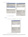
Take an example of editing the folder for WebDAV.
1.
Click the Edit icon of the folder.
2.
Click WebDAV tab.
Copyright@2014 D-Link System, Inc. All Rights Reserved.
52
D-Link Document – User Manual
3.
Click the check box to share the folder by WebDAV protocol.
4.
Select the permission of the Users and groups. Check the radio box of Access right for Readonly or Read/Write. And then select the users.
5.
Click Apply button.
Take an example of creating a folder.
1.
Click the Create folder icon of the folder.
2.
Enter a folder name.
3.
Click the check box to share the folder by CIFS, NFS, AFP, FTP or WebDAV protocols.
4.
Click Apply button.
Take an example of searching the files.
Copyright@2014 D-Link System, Inc. All Rights Reserved.
53
D-Link Document – User Manual
1.
Click the Search files icon.
2.
Enter a file name which wants to be searched. It can use wildcard “*”.
3.
Click Apply button.
4.
The results will be displayed in the Search results area.
Shares
The Sharing tab of the operation area is provided to remove the share or view the status of the
shares.
This table shows the column descriptions.
Column Name
Path
Pool
ZFS
CIFS name
NFS name
AFP name
FTP name
WebDAV name
Description
Share directory.
Pool name.
ZFS name.
Share name for CIFS.
Share name for NFS.
Share name for AFP.
Share name for FTP.
Share name for WebDAV.
The function is available on the share:
Delete: Delete the share.
Copyright@2014 D-Link System, Inc. All Rights Reserved.
54
D-Link Document – User Manual
LUN
The LUN option provides functions to manage iSCSI volumes such as attach, detach or view the
status of logical unit numbers for each volume.
This table shows the column descriptions.
Column Name
Target
LUN
Permission
ZFS name
Description
The number of the target.
The number of the LUN assigned.
The permission level:
Read/Write.
Read-only.
The name of the volume assigned to this LUN.
The functions are available in this tab:
LUN Attach: Attach a logical unit number from a volume.
LUN Detach: Detach a logical unit number from a volume.
Take an example of attaching a LUN.
1.
Click the LUN Attach icon.
2.
Select the volume from the drop-down list.
3.
Select the Target number from the drop-down list.
4.
Select the LUN number from the drop-down list.
5.
Choose the Permission level.
6.
Click Apply button.
Copyright@2014 D-Link System, Inc. All Rights Reserved.
55
D-Link Document – User Manual
Snapshot
The Snapshot option provides functions to manage snapshot activities such as take snapshot,
rollback, clone, delete, or view the status of the snapshots.
Snapshot can only be applied to the whole file system or volume. Snapshot cannot be applied to
specific shared folders.
This table shows the column descriptions.
Column Name
Name
Used (MB)
Refer (GB)
Created time
Description
The snapshot name.
The amount of snapshot space that has been used.
The refer capacity of the file system or volume.
The time the snapshot is created.
The functions that are available in this tab:
Take Snapshot: Take a snapshot.
Clone: Clone the file system or volume.
Rollback: Rollback the snapshot file system or volume.
Delete: Delete the snapshot file system or volume.
Take an example of taking a snapshot.
1.
Click the Take snapshot icon.
2.
Use the drop-down list to select a ZFS name.
3.
Enter a Snapshot name for the snapshot.
4.
Click Apply button.
Copyright@2014 D-Link System, Inc. All Rights Reserved.
56
D-Link Document – User Manual
Snapshot Schedule
The Snapshot schedule tab provides the functions to set schedule snapshots.
This table shows the column descriptions.
Column Name
Name
Schedule type
Description
Description
The snapshot name.
Disabled or Scheduled.
Schedule details.
The functions are available in this tab:
Set schedule: Set the snapshot schedule on a file system or a volume.
Edit: Modify the schedule settings.
Delete: Delete the schedule snapshot.
Take an example of setting a schedule snapshot.
1.
Click the Set schedule icon.
2.
Select the ZFS name.
3.
Select the radio box for Hourly, Daily or Weekly. According to the different schedule type,
input the proper parameters.
Application Configuration
The Application configuration menu option is for accessing the Directory service, CIFS, NFS, AFP,
FTP, WebDAV, iSCSI, Backup and AntiVirus options.
Copyright@2014 D-Link System, Inc. All Rights Reserved.
57
D-Link Document – User Manual
Directory Services
The Directory services option provides three directory services. Default is Standalone, which
supports local account only. The others are Active Directory for Windows and LDAP services.
UnifiedAUTH mechanism is the backbone of all the directory services. It simplifies the use of all
the data services (CIFS, NFS, AFP, FTP, WebDAV, iSCSI) and frees the users from memorizing
different account/password sets for different data services. The benefits are:
Easier use of all data services
Simplified management
Only one directory service can be enabled at all time. No two directory services can be enabled at
the same time. Switching directory service will result in losing Access Control List of all shares from
the previous directory service.
Select the radio button to change the directory service:
Standalone
Standalone support local user/group accounts only. It’s the default setting.
When it is done, click Apply button.
Active Directory
Active Directory service supports Windows Server 2003 and 2008 Active Directory to
manage the accounts. The maximum number of AD users and groups is 65536.
Enter the settings of Active Directory above. When it is done, click Apply button. If the
information is correct, the AD accounts will be added in System configuration -> Account ->
User account -> Domain user and Group account -> Domain group. It will take some time to
download the accounts at the first time. And then it will synchronize with the server
automatically.
TIP:
In order to make sure you can successfully login Active Directory server, please
make sure the following two requirements are met.
Primary DNS (Domain Name Server) setting is identical to that of the Active
Directory server.
The system time is synchronous with that of the Active Directory server with
less than 1 minute tolerance.
Copyright@2014 D-Link System, Inc. All Rights Reserved.
58
D-Link Document – User Manual
LDAP
LDAP (Light-weighted Directory Access Protocol) service supports LDAP version3 to manage
the accounts. The maximum number of LDAP users and groups is 65536.
Enter the settings of LDAP above. When it is done, click Apply button. If the information is
correct, the accounts will be added to System configuration -> Account -> User account ->
Domain user and Group account -> Domain group.
Base DN: The base distinguished name (DN) indicates where in the LDAP directory you wish
to load users and groups. It is the top level of the LDAP directory tree to be used when
searching for resources. Suppose that all user accounts and groups are located in the “Users”
folder under your domain. In LDAP form, it is cn=Users,dc=<your domain>. Let’s say your
domain is aaa.bbb.com. The Base DN you should put in is cn=Users,dc=aaa,dc=bbb,dc=com.
Admin DN: By default, the administrator DN is in the form cn=Administrator,dc=<your
domain>.
Using
previous
example,
The
Admin
DN
should
be
put
in
cn=Administrator,dc=aaa, dc=bbb,dc=com.
TIP:
Please contact your LDAP server administrator for the correct login parameters
for Base DN, Admin DN, User base DN, and Group base DN.
Copyright@2014 D-Link System, Inc. All Rights Reserved.
59
is
D-Link Document – User Manual
CIFS Service
The CIFS (Common Internet File System) option is used to setup CIFS protocol. The CIFS is a network
protocol that offers file services for Windows computers. The unified storage provides CIFS
capability without the need for a Windows server in the network. Starting this service will open the
following ports on the unified storage system:
TCP 139 (smbd)
TCP 445 (smbd)
UDP 137 (nmbd)
UDP 138 (nmbd)
This table shows the row descriptions.
Row Name
CIFS Service
Server description
Workgroup
WINS server 1 IP
address
WINS server 2 IP
address
Description
Enable or Disable.
Default is “Welcome to CIFS server”. Maximum length is 256 characters.
Default is “Workgroup”. Maximum length is 16 characters.
WINS Server IP Address. Default is empty. If it’s empty, the name
resolution priority is DNS only. Otherwise, the name resolution priority is
WINS server first, and then DNS.
The same as above.
When it is done, click Apply button.
NFS Service
The NFS (Network File System) option is used to setup NFS protocol. NFS is a protocol for sharing
files and directories on a network among Linux machines and Unix machines.
Starting this service will open the following ports on the unified storage system:
TCP 111 (rpcbind)
TCP 2049 (nfsd)
UDP 111 (rpcbind)
Additionally, mountd and rpcbind will each bind to a randomly available UDP port.
Copyright@2014 D-Link System, Inc. All Rights Reserved.
60
D-Link Document – User Manual
If you are using NFSv4 protocol, please make sure NFSv4 domain is provided in order to have ID
mapping function working correctly. When it is done, click Apply button.
AFP Service
The AFP (Apple Filing Protocol) option is used to setup AFP protocol. The AFP is a network protocol
that offers file sharing services for Mac computers.
Starting this service will open the following ports on the unified storage system:
TCP 548 (afpd)
TCP 4799 (cnid_metadata)
UDP 5353 and a random UDP port (avahi).
Enable or Disable the AFP protocol, and then click Apply button.
FTP Service
The FTP (File Transfer Protocol) option is used to setup FTP protocol. It allows you to configure the
FTP server so that users can browse and download data using their web browser or FTP client
software. FTP is easy to use and it is cross-platform. All major operating systems have FTP client
function.
Copyright@2014 D-Link System, Inc. All Rights Reserved.
61
D-Link Document – User Manual
This table shows the row descriptions.
Row Name
FTP Service
Login banner
Clients
Connections
Login attempts
Timeout
Minimum passive
port
Maximum passive
port
Upload
bandwidth(KB/s)
Download
bandwidth(KB/s)
Description
Enable or Disable.
Configurable login banner. Default is “Welcome to FTP server”. Max
characters are 256.
The maximum number of simultaneous clients, default is 20, range is 1 ~
4096.
The maximum number of connections per IP address, default is 32, range is
1 ~ 32.
The maximum number of attempts before client is disconnected, default is
3, range is 3 ~ 32.
The maximum client idle time in seconds before client is disconnected,
default is 60 (sec), valid values are 30, 60, 300, 600, 1800, 3600.
The minimum passive port, default is 49152, range is 1024 ~ 65535.
The maximum passive port, default is 65534, range is 1024 ~ 65535.
The upload bandwidth, in KB/s, default is 0 (no limit)
The download bandwidth, in KB/s, default is 0 (no limit)
When it is done, click Apply button.
WebDAV Service
The WebDAV (Web Distributed Authoring and Versioning) option is used to setup WebDAV
protocol. It is an extension of HTTP v1.1 protocol that allows users to manage files across different
operating system platforms. Starting this service will open the following ports on the unified
storage system:
TCP 80 (httpd)
Enable or Disable the WebDAV protocol, and then click Apply button.
iSCSI
The iSCSI (Internet SCSI) option is used to setup iSCSI entity name for block-based access. iSCSI is a
protocol standard that allows the consolidation of storage data. iSCSI allows the system to act like a
storage area network (SAN) over an existing Ethernet network. Specifically, it exports disk devices
over an Ethernet network that iSCSI clients (called initiators) can attach to and mount.
Copyright@2014 D-Link System, Inc. All Rights Reserved.
62
D-Link Document – User Manual
iSCSI Entity
This tab can modify iSCSI entity name.
Enter the iSCSI entity name, and then click Apply button.
iSCSI Node
This tab can manage iSCSI node.
Click Set Properties icon to set the iSCSI properties.
CHAP (Challenge Handshake Authentication Protocol) is a strong authentication method used in
point-to-point for user login. It’s a type of authentication in which the authentication server sends
the client a key to be used for encrypting the username and password. CHAP enables the
username and password to transmit in an encrypted form for protection.
If you want to use CHAP authentication, select CHAP from the drop-down list, and then click Apply
button.
Copyright@2014 D-Link System, Inc. All Rights Reserved.
63
D-Link Document – User Manual
Click Set User icon to set the iSCSI CHAP users.
Multi-select which CHAP user(s) will be used and click the >> button. It can be more than one, but
it must be at least one for CHAP to work. When it’s done, click Apply button.
Backup
The Backup option provides functions to set up the backup services. Currently, it supports
Replication and Amazon S3 services.
Both Amazon S3 and replication services are applied to the whole file system or volume, which is
the right next level to the storage pool. None of backup services can be applied to specific shared
folders.
Replication
The Replication tab is used to setup the replication service. It supports local cloning and remote
replication to other unified storage arrays. There is no limit to the number of how many local
cloning and remote replication tasks can be created. If you experience slow system performance,
please reduce the replication tasks. It supports one-to-one replication tasks but not one-to-many.
The same replication source cannot coexist in different tasks. The max task number is limited as 16
tasks.
Copyright@2014 D-Link System, Inc. All Rights Reserved.
64
D-Link Document – User Manual
This table shows the column descriptions.
Column Name
Task name
ZFS
Target IP
Target ZFS
Status
Schedule
Created time
Last executed
time
Result
Spare slot
Description
The task name.
The source name of the file system or volume.
Local or the remote target IP.
The target name of the file system or volume.
Standby or Running.
Disabled or scheduled.
The created time of the task.
The last executed time.
The physical disk slots of the RAID set.
The spare physical disk slot.
The functions available in this tab are:
Create: Add a replication task.
Start: Start the task.
Stop: Stop the task.
Schedule: Schedule the task.
Delete: Delete the task.
Take an example of adding a task.
1.
Click Create icon.
2.
Enter the Task name, and select a file system or volume to replicate. Then click Next button.
3.
Select the Local cloning or Remote replication. Remote replication needs to enter the target
IP, username and password. And then click Next button.
4.
Select the target pool and enter a name. And then click Next button.
5.
At the confirmation message, click Apply button.
Amazon S3
The Amazon S3 tab is used to setup the popular cloud backup service provided by Amazon. Before
using the service, you must register an Amazon S3 account first at http://aws.amazon.com/s3/.
There is no limit to the number of how many Amazon S3 tasks can be created. If you experience
slow system performance, please reduce the Amazon S3 tasks.
Copyright@2014 D-Link System, Inc. All Rights Reserved.
65
D-Link Document – User Manual
This table shows the column descriptions.
Column Name
Task name
Type
ZFS
Folder
S3 bucket
S3 folder
Status
Schedule
Created time
Description
The task name.
Upload or download.
The source name of the file system or volume.
The folder name.
The S3 bucket name.
The S3 folder name.
Standby or Running.
Disabled or scheduled.
The created time of the task.
The functions are available in this tab:
Create: Add a backup task to Amazon S3 service.
Edit: Edit the task.
Start: Start the task.
Stop: Stop the task.
Schedule: Schedule the task.
Delete: Delete the task.
Take an example of adding a task.
1.
Click Create icon.
2.
Enter the Task name, select the Local path, and enter the folder.
3.
Select the Backup type, Upload or Download, enter the Access key, Private Key and the
Bucket/Folder for Amazon S3 settings. Check the box when you need to delete extra files in
the destination folder.
4.
Click Test connection button to test the connection if necessary.
5.
Click Apply button to create a task.
AntiVirus
The AntiVirus option is for accessing the AntiVirus service, AntiVirus scan filter, AntiVirus task,
AntiVirus update and AntiVirus report option tabs. It uses McAfee antivirus engine which is an
American global computer security software company.
Copyright@2014 D-Link System, Inc. All Rights Reserved.
66
D-Link Document – User Manual
AntiVirus Service
This tab can enable or disable antivirus service.
Check Enable or Disable button, and then click Apply button.
AntiVirus Scan Filter
This tab manages what files exclude to be scanned.
Click Add icon of the Exclude file type, add a text for file extension, then click Add button. These
file extensions will be skipped when executing antivirus scanning. The same goes for Exclude share.
AntiVirus Task
This tab manages the antivirus tasks.
This table shows the column descriptions.
Column Name
Task name
Pool
File system
Path
Description
The task name.
The pool name.
The file system name.
The path of the file system.
Copyright@2014 D-Link System, Inc. All Rights Reserved.
67
D-Link Document – User Manual
Status
Schedule
Created time
Standby or Running.
Disabled or scheduled.
The created time of the task.
The functions are available in this tab:
Create: Add a antivirus task.
Start: Start the task.
Stop: Stop the task.
Schedule: Schedule the task.
Delete: Delete the task.
AntiVirus Update
This tab manages the update of virus pattern files.
Select Enable to enable Auto update, enter a number for the amount of days the update will
execute automatically. Click Apply button to take effect.
Or click Update Now button to update immediately. If you have the update file, it also can be
updated manually.
AntiVirus Report
This tab displays the report of the infected files.
Copyright@2014 D-Link System, Inc. All Rights Reserved.
68
D-Link Document – User Manual
Click Download icon to save the report.
Maintenance Configuration
The Maintenance Configuration menu option is for accessing the Download, Reset to factory
default, Firmware upgrade, Reboot, and Shutdown options.
Download
Download option provides two services. There are Download MIB file and Download system
information.
Download MIB File
The Download MIB file tab provides to download MIB file for SNMP usage.
Download System Information
The Download system information tab will download a compressed file to your local drive. It
contains event logs, debug information, and system configuration data. Please send this
compressed file to us when you need technical assistance.
Reset to Factory Default
The Reset to factory default option allows users to reset the system configurations back to the
factory default settings.
Copyright@2014 D-Link System, Inc. All Rights Reserved.
69
D-Link Document – User Manual
It will perform the following major tasks
Restore Admin password to 1234
Reset management port to DHCP. If the network environment does not have DHCP server,
the IP address will fallback to zero config.
Clear all user/group accounts and default directory service to Standalone.
Clear all access right settings for shares.
Clear all snapshot, replication, backup tasks.
Please be aware that “Reset to factory defaults” will not delete the user data in UserHome file
system. If you create a local user account with the very same name, the system will see it as the
same user and use the original user account folder.
Firmware Upgrade
The Firmware Upgrade is used to upgrade controller firmware.
Please prepare new controller firmware file named “xxxx.bin” in local hard drive, then click
Browse to select the file. Click Upgrade button to start upgrading the firmware. When upgrading,
there is a percentage displayed. After upgrading is finished, the system must reboot manually so
the new firmware can take effect.
Firmware Upgrade via USB
Below are the instructions of how to use this function and some requirements.
1.
Copy the checksum file (md5sum.txt) and firmware file (*.bin or *.flash) to the root of USB
drive.
2.
In the root of USB drive, create a pure text file named AutoRun.ini with the following
content.
Copyright@2014 D-Link System, Inc. All Rights Reserved.
70
D-Link Document – User Manual
[upgrade]
upgrade_md5file = md5sum.txt
3.
Insert USB drive to the USB port shown below in different models.
4.
The system will detect USB drive and the firmware. If the setting is correct, the firmware will
start upgrading will automatically. The web UI does not have a progress meter.
5.
If upgrading is successful, the hard drive LED will blink for 10 seconds and the buzzer will be
on for 10 seconds. If upgrading fails, the hard drive LED and the buzzer will turn on for 2
seconds and off for 2 seconds 3 times.
Some requirements:
USB drive file system supports NTFS and FAT32 only.
Firmware file name cannot be renamed.
During firmware upgrading, USB drive cannot be pulled out.
If firmware version is the same, upgrading will not start.
Reboot
The Reboot option is used to reboot the system.
Shutdown
The Shutdown option is used to shutdown the system. Before powering off the system, it is highly
recommended to execute Shutdown function to flush the data from cache onto the physical disks.
The step is important for data protection.
Copyright@2014 D-Link System, Inc. All Rights Reserved.
71
D-Link Document – User Manual
Access Shares from Your Operating System
Introduction
There are five data services provided by the Unified Storage. This chapter will show you how to
access shares from different operating systems. We will introduce CIFS/Samba, NFS, FTP, AFP, and
WebDAV. Before you can access the shares, please make sure that you have enabled file sharing
services and related settings in Sharing of Chapter 4.
CIFS and Windows
There are several ways to access a network share in Windows XP and Windows 7 operating
systems. It all follows Windows UNC (Universal Naming Convention) format.
Syntax:
\\<NAS system name>\<share name>
\\<IP address of NAS>\<share name>
<NAS system name> can be found from menu bar System Configuration -> System.
<IP address of NAS> is the IP address of one of the network ports. It can be found from menu bar
Network Configuration -> Network Setting.
Method 1: The Address Input in Explorer
Open a Windows Explorer from Start button or by pressing Start key + E. In the address input, put
in the share path and press Enter. Please refer to the screenshot below.
Copyright@2014 D-Link System, Inc. All Rights Reserved.
72
D-Link Document – User Manual
Windows will pop up a dialog requesting for an account and password. Please put in your account
and password. When the authentication is clear, the share is ready for you to use as follows:
Method 2: The Command Line Input from Start Button
Click Start button to bring up the start menu. In the command line input, put in the share path and
press Enter. The rest is the same as described in Option 1.
Copyright@2014 D-Link System, Inc. All Rights Reserved.
73
D-Link Document – User Manual
Method 3: Map a Network Drive in Explorer
Please follow the steps below to map a network share from the unified storage to a drive letter.
The network share will be automatically mapped the next time you boot your Windows.
1.
Open a Windows Explorer from Start button or by pressing Start key + E. Go to Tools and
select Map network drive.
2.
Select the drive letter you like. Put the share path in Folder. Make sure you check Reconnect
at logon. Click Finish.
Copyright@2014 D-Link System, Inc. All Rights Reserved.
74
D-Link Document – User Manual
3.
You may find a new drive with the letter you just selected in Explorer. You may start using
the new drive then.
NFS and Linux
The Unified Storage supports NFS version 3 and version 4. If version 4 connections cannot be
established, the system will automatically try to establish the connection using version 3 protocols.
Before using the NFS shares, please make sure the NFS settings of the shares are properly
configured.
Redhat Linux 5
When mounting a file system in Redhat Linux 5, Redhat Linux 5 uses NFS version 3 by default. Use
the following syntax to mount an NFS share. Please make sure you add the keyword – nfs-share
before the share name. It represents the absolute path that the end user doesn’t need to know.
Copyright@2014 D-Link System, Inc. All Rights Reserved.
75
D-Link Document – User Manual
mount <IP address of NAS>:/nfs-share/<share name> <mount point>
For example:
mount 192.168.8.180:/nfs-share/SQL_DB2 /mnt/nas
Redhat Linux 6
The default attempt will try to use NFS version 4 protocol to set up connection in Redhat Linux 6.
Use the following syntax to mount an NFS share.
mount <IP address of NAS>:/<share name> <mount point>
For example:
mount 192.168.8.180:/SQL_DB2 /mnt/nas
Open Solaris 10/11
Open Solaris 10/11 will use NFS version 4 as a default. Use the following syntax to mount an NFS
share.
mount -F nfs -o rw <IP address of NAS>:/<share name> <mount point>
For example:
mount -F nfs -o rw 192.168.8.180:/SQL_DB2 /mnt/nas
NFS and vShpere5
/nfs-share/<share name>
Copyright@2014 D-Link System, Inc. All Rights Reserved.
76
D-Link Document – User Manual
IP address of NAS
NFS share name
AFP and Mac OS X
In Finder, go to Go and select Connect to Server. Put in the network port IP address that you want
to access. Click Connect.
It will bring up a window requesting account and password. Please put in your account and
password. Click Connect.
Copyright@2014 D-Link System, Inc. All Rights Reserved.
77
D-Link Document – User Manual
A window with all accessible shares for AFP protocol will pop up for you to select the share you
want to connect to. Click OK.
There you go. The share is ready for you to access.
Apple Time Machine Support
It’s very easy and straight forward to use Apple Time Machine with the unified storage. Simply
follow the same instructions above to create AFP shares on the Mac machine and do the steps
below.
1.
Go to Time Machine function.
2.
Turn on Time Machine. Click Select Disk.
3.
Select the share and put in account and password again.
4.
Start Time Machine operation.
Copyright@2014 D-Link System, Inc. All Rights Reserved.
78
D-Link Document – User Manual
FTP
FTP is the basic file transfer tool provided in almost all operating systems. You may use FTP
function through command line shell, FTP client, or web browsers.
Method 1: Using Command Line Shell
In Windows XP or Windows 7, open a command line window and use FTP command – “ftp”. Enter
your account and password. The share is available for you to access.
In Red Hat Linux, it looks like the screenshot below.
Copyright@2014 D-Link System, Inc. All Rights Reserved.
79
D-Link Document – User Manual
Method 2: Using FTP Client Application
There are a lot of FTP client tools in Windows platform such as WSFTP, FileZilla. In Linux X-Window
environment, there are gFTP, WXftp, and LLNL XFTP.
For example, using FileZilla in Windows looks like the screenshot below.
Copyright@2014 D-Link System, Inc. All Rights Reserved.
80
D-Link Document – User Manual
WebDAV
The Unified Storage WebDAV service supports the following operating systems :
32bit Windows : Windows XP SP2, Windows 7 SP1, Windows Server 2008 SP1
64bit Windows operating systems have issues to support WebDAV service. We recommend
rd
using 3 party WebDAV client applications.
32bit Redhat Linux 5 and 6
64bit Redhat Linux 6
If you are using Windows XP or Vista, you may need to install a Windows update KB907306. If you
are using Windows 7, please make sure WebClient service is enabled through Component Services.
For more related information, please check WebDAV client interoperability at http://svnbook.redbean.com/en/1.6/svn.webdav.clients.html
Method 1: Windows 7 Using Map Network Drive Wizard
From Windows Explorer, go to Tools and select Map Network Drive.
From Network and Sharing Center in the Control Panel, go to Tools and select Map Network Drive.
Copyright@2014 D-Link System, Inc. All Rights Reserved.
81
D-Link Document – User Manual
From the Computer icon on Desktop, right click on Computer icon and select Map Network Drive.
When the wizard appears, click Connect to a Web site that you can use to store your documents
and pictures.
Copyright@2014 D-Link System, Inc. All Rights Reserved.
82
D-Link Document – User Manual
Follow the instructions and click Next. Select Choose a custom network location and click Next.
Copyright@2014 D-Link System, Inc. All Rights Reserved.
83
D-Link Document – User Manual
In Internet or network address input, put in the WebDAV share in the following syntax.
http://<IP address>: 50000/<WebDAV share>
Please make sure you put in the port number 50000.
Put in the required account and password information. You may name the network location. Here
we simply use the default as 192.168.122.112.
You may access the web folder now.
Copyright@2014 D-Link System, Inc. All Rights Reserved.
84
D-Link Document – User Manual
Method 2: Using 3rd Party WebDAV Client Appplication
Recommended tools include WebDrive, NetDrive, or Bitkinex.
Copyright@2014 D-Link System, Inc. All Rights Reserved.
85
D-Link Document – User Manual
Software Application
6
Microsoft iSCSI Initiator
Here are the step by step instructions of how to setup Microsoft iSCSI Initiator. Please visit
Microsoft website for latest iSCSI initiator. This example is based on Microsoft Windows Server
2008 R2.
Connect to iSCSI Target
1.
Run Microsoft iSCSI Initiator.
2.
Input IP address or DNS name of the target. And then click Quick Connect button.
3.
Select the target name, and then click Done button.
Copyright@2014 D-Link System, Inc. All Rights Reserved.
86
D-Link Document – User Manual
4.
It can connect to an iSCSI disk now.
Disconnect
1.
Select the target name, click Disconnect button, and then click Yes button.
2.
Done, the iSCSI device disconnected successfully.
Copyright@2014 D-Link System, Inc. All Rights Reserved.
87
D-Link Document – User Manual
Advanced Operations
Terminal Operations
There are two terminal operations to manage and debug the storage system, these are described
below.
Serial Console
At the rear of the storage system, connect a monitor via the VGA port and connect a USB keyboard
via the USB port.
The initial defaults for administrator login are:
User name: admin
Password: 1234
Secure Shell Remote Access
SSH (secure shell) software is required for remote login. The SSH client software is available at the
following web site:
SSH Tectia Client: http://www.ssh.com/
PuTTY: http://www.chiark.greenend.org.uk/
The default IP setting is DHCP, check the LCM to find the IP address. If your network does not have
DHCP server, you will need to configure a static IP address. The remote control settings are on the
following:
Host IP: <IP Address> (e.g.: 192.168.10.50)
Port: 2222
User name: admin
Password: 1234
TIP:
The system supports SSH for remote access only. When using SSH, the IP
address and password are required for login.
Copyright@2014 D-Link System, Inc. All Rights Reserved.
88
D-Link Document – User Manual
Console UI
When logged into the system, there is a prompt, type help and press Enter button. It will display
help description.
console> help
info
Print system information
ifconfig
Setting eth0 IP address
reset_network Reset all of network port to Manufactory setting
restart_http
Restart HTTP service for management
list_port
List the port number of service used
diag
Print diagnostic message
dump_sysinfo
Dump system information to USB
exit
Exit
help
Help description
console>
These options are available on the console UI:
info: Print the system information.
console> info
[System]
Product:
DNS-1560-04
Name:
DNS-1560-04-xxxx
Version:
1.2.3
[Network]
LAN0 => MAC 00:13:78:xx:xx:xx
Addr:192.168.10.50
LAN1 => MAC 00:13:78:xx:xx:xx
Addr:169.254.200.61
LAN2 => MAC 00:13:78:xx:xx:xx
Addr:169.254.131.177
LAN3 => MAC 00:13:78:xx:xx:xx
Addr:169.254.190.59
Mask:255.255.0.0
Mask:255.255.0.0
Mask:255.255.0.0
Mask:255.255.0.0
ifconfig: Setup the IP address of the management port.
console> ifconfig
Setting eth0 IP address usage:
ifconfig IP MASK [GATEWAY]
ifconfig DHCP
reset_network: Reset all of network ports to factory default setting.
restart_http: If the web UI is abnormal, restart HTTP service for management.
list_port: List the port number of the services.
console> list_port
[Service]
[Port]
http
=> 80
https
=> 443
Copyright@2014 D-Link System, Inc. All Rights Reserved.
89
D-Link Document – User Manual
ssh
=> 2222
ftp
=> 21
sftp
=> 22
webdav
=> 50000
webdavs
=> 8888
diag: Print the diagnostic messages.
dump_sysinfo: Connect a USB flash via USB port at the rear of the system, use this command
to dump the system information on the USB device.
reboot: Reboot the system.
shutdown: Shutdown the system.
exit: Exit the console UI.
help: Display the help description.
Copyright@2014 D-Link System, Inc. All Rights Reserved.
90
D-Link Document – User Manual
Glossary and Acronym List
Common Terminology
Item
RAID
PD
Pool
ZFS
LUN
GUI
RO
DS
DG
SCSI
SAS
S.M.A.R.T.
WWN
HBA
NIC
BBM
Description
Redundant Array of Independent Disks. There are different RAID levels
with different degree of data protection, data availability, and
performance to host environment.
The Physical Disk belongs to the member disk of one specific RAID group.
A collection of removable media. One pool consists of one or several RAID
sets.
ZFS is a combined file system and logical volume manager designed by Sun
Microsystems. The features of ZFS include data integrity verification
against data corruption modes, support for high storage capacities,
integration of the concepts of file system and volume management,
snapshots and copy-on-write clones, continuous integrity checking.
Logical Unit Number. A logical unit number (LUN) is a unique identifier
which enables it to differentiate among separate devices (each one is a
logical unit).
Graphic User Interface.
Set the volume to be Read-Only.
Dedicated Spare disks. The spare disks are only used by one specific RG.
Others could not use these dedicated spare disks for any rebuilding
purpose.
DeGraded mode. Not all of the array’s member disks are functioning, but
the array is able to respond to application read and write requests to its
virtual disks.
Small Computer Systems Interface.
Serial Attached SCSI.
Self-Monitoring Analysis and Reporting Technology.
World Wide Name.
Host Bus Adapter.
Network Interface Card.
Battery Backup Module
Data Service Terminology
Item
CIFS
SMB
NFS
AFP
Description
Common Internet File System. CIFS operates as an application-layer
network protocol mainly used for providing shared access to files, printers,
serial ports, and miscellaneous communications between nodes on a
network.
Server Message Block. Same as CIFS.
Network File System. NFS is a distributed file system protocol originally,
allowing a user on a client computer to access files over a network in a
manner similar to how local storage is accessed.
Apple Filing Protocol, formerly AppleTalk Filing Protocol. AFP is a
proprietary network protocol that offers file services for Mac OS X and
original Mac OS. In Mac OS X, AFP is one of several file services supported
Copyright@2014 D-Link System, Inc. All Rights Reserved.
91
D-Link Document – User Manual
FTP
WebDAV
Thin Provisioning
including Server Message Block (SMB), Network File System (NFS), File
Transfer Protocol (FTP), and WebDAV. AFP currently supports Unicode file
names, POSIX and access control list permissions, resource forks, named
extended attributes, and advanced file locking. In Mac OS 9 and earlier, AFP
was the primary protocol for file services.
File Transfer Protocol. FTP is a standard network protocol used to transfer
files from one host or to another host over a TCP-based network, such as
the Internet.
Web Distributed Authoring and Versioning. WebDAV is an extension of the
Hypertext Transfer Protocol (HTTP) that facilitates collaboration between
users in editing and managing documents and files stored on World Wide
Web servers.
Thin provisioning is the act of using virtualization technology to give the
appearance of having more physical resources than are actually available.
The term thin provisioning is applied to disk later in this article, but could
refer to an allocation scheme for any resource.
iSCSI Terminology
Item
iSCSI
LACP
MPIO
MC/S
MTU
CHAP
iSNS
Description
Internet Small Computer Systems Interface.
Link Aggregation Control Protocol.
Multi-Path Input/Output.
Multiple Connections per Session
Maximum Transmission Unit.
Challenge Handshake Authentication Protocol. An optional security
mechanism to control access to an iSCSI storage system over the iSCSI data
ports.
Internet Storage Name Service.
Copyright@2014 D-Link System, Inc. All Rights Reserved.
92
D-Link Document – User Manual
Index
FTP (File Transfer Protocol) ................................................ 61
A
AFP (Apple Filing Protocol) ............................................... 61
Amazon S3 .......................................................................... 65
AntiVirus
AntiVirus Report ............................................................. 68
AntiVirus Scan Filter ...................................................... 67
AntiVirus Service ............................................................ 67
AntiVirus Task ................................................................ 67
AntiVirus update ............................................................. 68
Application Configuration ................................................... 57
AFP Service .................................................................... 61
AntiVirus......................................................................... 66
Backup Service ............................................................... 64
CIFS Service ................................................................... 60
Directory Services ........................................................... 58
FTP Service ..................................................................... 61
iSCSI ............................................................................... 62
NFS Service .................................................................... 60
WebDAV Service ........................................................... 62
B
Backup
Amazon S3 ...................................................................... 65
Replication ...................................................................... 64
C
CE Statement ......................................................................... 4
CHAP (Challenge Handshake Authentication Protocol) ..... 63
CIFS (Common Internet File System) ................................. 60
Compression ........................................................................ 48
Connection .......................................................................... 28
Console UI........................................................................... 89
D
Dashboard............................................................................ 23
Directory services
Active Directory .............................................................. 58
LDAP .............................................................................. 59
Standalone ....................................................................... 58
Download
Download MIB File ........................................................ 69
Download System Information ....................................... 69
Drive Slot Numbering ......................................................... 16
E
Event log ............................................................................. 27
F
FCC Statement ...................................................................... 4
Firmware Upgrade via USB ................................................ 70
Copyright@2014 D-Link System, Inc. All Rights Reserved.
G
GUI (Graphic User Interface) .............................................. 18
H
Hardware monitor ................................................................ 27
I
iSCSI
iSCSI Entity..................................................................... 63
iSCSI Note....................................................................... 63
iSCSI (Internet SCSI) .................................................... 15, 62
iSCSI Concepts .................................................................... 15
iSCSI Initiator ...................................................................... 86
Connect............................................................................ 86
Disconnect ....................................................................... 87
M
Maintenance Configuration.................................................. 69
Download ........................................................................ 69
Firmware Upgrade ........................................................... 70
Reboot ............................................................................. 71
Reset to Factory Default .................................................. 69
Shutdown ......................................................................... 71
Monitor ................................................................................ 24
N
NAS Concepts...................................................................... 14
Network Configuration ........................................................ 37
DNS Setting..................................................................... 39
Network Setting ............................................................... 37
NFS (Network File System) ................................................. 60
NTP (Network Time Protocol)............................................. 30
P
Physical disk ........................................................................ 25
R
RAID Concepts .................................................................... 13
RAID Levels ........................................................................ 13
Replication ........................................................................... 64
S
S.M.A.R.T............................................................................ 24
Secure Shell Remote Access ................................................ 88
Serial Console ...................................................................... 88
Setup Wizard........................................................................ 21
93
D-Link Document – User Manual
Share
Explorer........................................................................... 50
Shares .............................................................................. 54
Snapshot .............................................................................. 26
Snapshot .......................................................................... 56
Snapshot Schedule .......................................................... 57
SSH (Secure Shell) .............................................................. 88
Storage Configuration ......................................................... 40
LUN ................................................................................ 55
Physical Disk .................................................................. 40
Pool ................................................................................. 42
Share ............................................................................... 49
Snapshot .......................................................................... 56
ZFS.................................................................................. 45
System Configuration .......................................................... 29
Account ........................................................................... 30
Mail Setting ..................................................................... 35
Messenger ....................................................................... 35
SNMP.............................................................................. 36
System ............................................................................. 29
Copyright@2014 D-Link System, Inc. All Rights Reserved.
System Log Server .......................................................... 36
Time ................................................................................ 30
System Installation and Deployment....................................16
T
Terminal Operations ............................................................ 88
Thin provisioning ................................................................. 47
U
UL Statement .........................................................................4
UPS ...................................................................................... 28
W
Web UI (Web User Interface) .............................................. 18
WebDAV (Web Distributed Authoring and Versioning) .....62
94
95