1
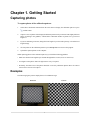
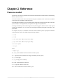
Agisoft Lens User Manual
Version 0.4.0
Agisoft Lens User Manual: Version 0.4.0
Publication date 2011
Copyright © 2011 AgiSoft LLC
Table of Contents
Agisoft Lens overview ....................................................................................................... iv
1. Getting Started ............................................................................................................... 1
Capturing photos ........................................................................................................ 1
Examples .......................................................................................................... 1
Loading photos .......................................................................................................... 2
Inspecting the loaded photos ................................................................................ 2
Supported image formats ..................................................................................... 2
Calibrating lens .......................................................................................................... 2
Calibration parameters ......................................................................................... 3
Converting calibration ................................................................................................. 3
2. Reference ...................................................................................................................... 5
Camera model ............................................................................................................ 5
iii
Agisoft Lens overview
Agisoft Lens is an automatic lens calibration software, which uses LCD screen as a calibration target.
It supports estimation of the full camera calibration matrix, including non-linear distortion coefficients.
Estimated calibration parameters can be saved in human readable file format for subsequent use in the
software, where precise camera calibration data is required.
Agisoft Lens estimates the following camera calibration parameters:
• fx, fy - focal length
• cx, cy - principal point coordinates
• K1, K2, K3, P1, P2 - radial distortion coefficients, using Brown's distortion model
iv
Chapter 1. Getting Started
Capturing photos
To capture photos of the calibration pattern:
1.
Select Show chessboard command from the Tools menu to display the calibration pattern or press
toolbar button.
2.
Capture a series of photos of the displayed calibration pattern with your camera from slightly different
angles, according to the guidlines, outlined below. Minimum number of photos for a given focal
length is 3.
3.
If you are calibrating zoom lens, change the focal length of your lens and repeat step 2 for other focal
length settings.
4.
Click anywhere on the calibration pattern or press Escape button to return to the program.
5.
Upload the captured photos to the computer.
When capturing photos of the calibration pattern, try to fulfill the following guidlines:
• Make sure that the focal length keeps constant throughout the session (in case of zoom lens).
• Avoid glare on the photos. Move the light sources away if required.
• Preferably, the whole area of the photos should be covered by calibration pattern. Move the camera
closer to the LCD screen if required.
Examples
The following figures present sample photos of a calibration target.
Incorrect
Correct
1
Getting Started
Loading photos
To load photos of the calibration pattern:
1.
Select Add Photos... command from the Tools menu or press
toolbar button.
2.
In the Open dialog box, browse to the folder, containing the photos, and select files to be processed.
Then click Open button.
3.
Selected photos will appear in the Photos pane.
If you have loaded some unwanted photos, you can easily remove them at any time.
To remove unwanted photos
1.
In the Photos pane select the photos to be removed.
2.
In the Tools menu, click Remove Photos or use
removed from the working set.
toolbar button. The selected photos will be
Inspecting the loaded photos
The loaded photos are displayed in the Photos pane. You can open any photo by double clicking on its
name. To obtain good calibration, the photos should be reasonably sharp, with crisp boundaries between
cells.
Supported image formats
The following image formats are supported by Agisoft Lens:
• Joint Photographic Experts Group (JPEG)
• Tagged Image File Format (TIFF)
• Portable Network Graphics (PNG)
• Portable Pixmap Format (PPM)
• Windows Bitmap (BMP)
Calibrating lens
To calibrate camera lens
1.
Capture and load the photos of the calibration pattern if you haven't done it already. See more details
in the Capturing photos and Loading photos sections.
2.
Select Calibrate... command in the Tools menu.
3.
In the Calibration dialog box, select the desired calibration parameters. Click OK button when done.
2
Getting Started
4.
The progress dialog box will appear displaying the current processing status. To cancel processing
click the Cancel button.
5.
The calibration results will appear in the Report window.
The following calibration parameters are estimated during calibration and printed in the Report window:
• fx - horizontal focal length, in pixels
• fy - vertical focal length, in pixels
• cx - X coordinate of the principal point
• cy - Y coordinate of the principal point
• K1, K2, K3, P1, P2 - radial lens distortions in the Brown's model
After calibration is finished, you will be presented with the following information:
Detected chessboard corners are displayed on each photo (the photo can be opened by double clicking on
its name in the Photos pane). It is preferable when the majority of the corners were detected correctly. For
each detected corner the reprojection error between the detected corner position and estimated position
according to the calculated calibration is also displayed. The errors are scaled x20 times for display.
In the Report window estimated calibration parameters and their errors are displayed. The plots of radial
and tangential distortion are also presented. For zoom lens these parameters are estimated for each focal
length separately. You can select the measurement to be displayed using EXIF focal length list.
Calibration parameters
Center principal point
When enabled, the principal point coordinates will be set to the center of the photo and will not be
optimized during calibration.
Square pixels
When enabled, X and Y focal lengths will be set to equal values during optimization.
Distortion model
Selects distortion coefficients to be estimated. Other distortion coefficients will be set to zero and
excluded from the optimization.
Converting calibration
Various software packages use slightly different camera models and parameter sets for their calibrations.
Agisoft Lens supports loading calibration data obtained using the following software packages: CalCam,
PhotoModeler, iWitness.
To load calibration from external software:
1.
Select Convert... command from the Tools menu.
2.
In the Convert dialog box select the type of calibration to be converted. Fill in image dimensions in
pixels and the values for all parameters in the list.
3.
Click OK button when done. The calibration will be converted and calibration parameters will be
displayed in the Report window.
3
Getting Started
Note
• CalCam calibration parameters can be imported automatically from the .cal file using Import...
button in the Convert dialog.
4
Chapter 2. Reference
Camera model
Agisoft Lens software uses a pinhole camera model for lens calibration. The distortions are modeled using
Brown's distortion model.
The camera model specifies the transformation from point coordinates in the local camera coordinate
system to the pixel coordinates in the image frame.
The local camera coordinate system is selected with the origin at the camera projection center. The Z axis
points towards the viewing direction, X axis points to the right, Y axis points down.
The image coordinate system has the origin at the top left image pixel, whith the center of the top left
pixel having coordinates (0.5, 0.5). The X axis in the image coordinate system points to the right, Y axis
points down.
For the point with (X, Y, Z) coordinates in the local camera coordinate system, the projected coordinates
in the image frame can be calculated using the following equations:
x=X/Z
y=Y/Z
x' = x(1 + K1r2 + K2r4 + K3r6) + P2(r2+2x2) + 2P1xy
y' = y(1 + K1r2 + K2r4 + K3r6) + P1(r2+2y2) + 2P2xy
u = cx + x'fx + y'skew
v = cy + y'fy
where:
r = sqrt(x2 + y2),
(X, Y, Z) - point coordinates in the local camera coorinate system,
(u, v) - projected point coordinates in the image coordinate system (in pixels),
(fx, fy) - focal lengths,
(cx, cy) - principal point coordinates,
K1, K2, K3 - radial distortion coefficients,
P1, P2 - tangential distortion coefficients,
skew - skew coefficient between the x and the y axis.
5