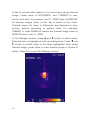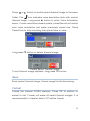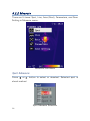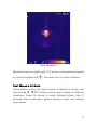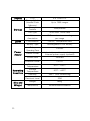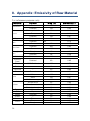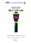
1
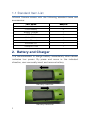
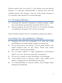
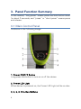
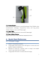
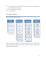
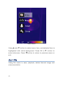
UFPA Infrared Camera
User Manual
Please read carefully before first use
WARNING
DO NOT USE WHEN RAINING!
DO NOT OPEN OR EXCHANGE PARTS!
REPAIR ONLY CAN BE CONDUCTED BY STUFF!
NOTICE
z
Directing device to strong light source (such as sun light)
is prohibited under any condition, including after power
down. This will cause malfunction or even critical damage
to the device.
z
Avoid shock and impact during operation or transport.
z
Device must be in original case during transport and
storage. Storage temperature is between -40℃ to 60℃.
z
Typical storage place is cool, dry, ventilated, and without
strong electrical or magnetic field.
z
Avoid oil or any chemical liquid on Infrared lens surface.
Close lens lid after operation.
z
Export and backup data on PC after operation. Format
internal
FLASH
memory
periodically
for
best
performance.
i
Table of Contents
1. Product Summary............................................................ 1
1.1 Standard Item List...................................................... 2
2. Battery and Charger ........................................................ 2
2.1 Charging Battery ........................................................ 3
2.2 Notes for Using Battery Charger ............................. 3
3. Panel Function Summary .............................................. 4
3.1 Main Control Panel .................................................... 4
3.2 Rear Interface Panel .................................................. 6
3.3 Side View .................................................................... 6
4. Quick Start Reference..................................................... 7
4.1 Infrared Image ............................................................ 7
4.2 Measure Target Temperature .................................. 8
4.3 Infrared Image and Voice Annotation...................... 8
4.4 Infrared Image Playback............................................ 9
4.5 Connect to PC ............................................................ 9
5. Operation Menu................................................................ 9
5.1 Display Summary ....................................................... 9
5.2 Main Menu................................................................ 11
5.2.1 File ..................................................................... 12
5.2.2 Measure............................................................ 16
5.2.3 Image ................................................................ 24
5.2.4 Setup ................................................................. 28
6. Technical Specification ................................................ 31
7. Technical Support ......................................................... 33
8. Appendix: Emissivity of Raw Material...................... 34
ii
1. Product Summary
This new generation Infrared Camera (equipped with Uncooled
Focal Plan Array Micro-bolometer) produces crisp thermal image
and accurate temperature reading to help increase system
maintenance quality and efficiency in many industries. Crisp
thermal image, accurate temperature reading, clear user
interface, reliable product quality, and affordable cost makes the
new standard in Infrared imaging industry!
Typical Application:
z
z
z
z
Power Plant: Monitor and diagnose the condition of
electrical wire and equipment, measure surface temperature,
detect power leak, and prevent system malfunction
Electronics: Monitor and control printed circuit board or LED
board temperature during the curing process; Locate poor
soldering, track discontinuities, incorrect component values
and power ratings as well as incorrect polarities in the
production place; and other type of applications in electronic
fields
Medical Application: Accurately measure human body
temperature in a distance, critical under a contaminated
condition
Other Applications: Constructions, civil engineering,
university research, and etc.
1
1.1 Standard Item List
Infrared Camera comes with the following standard items and
accessories:
Item Name
Quantity
Infrared Camera
1
Li-Ion Battery
Battery Charger
2
1
USB Cable
Video Cable
1
1
User Manual
1
Software CD
Transport Case
1
1
2. Battery and Charger
It is recommended to charge battery immediately when device
indicates low power. By press and move in the indicated
direction, user can easily insert and remove battery.
Battery Insertion
Battery Removal
2
Device comes with two sets of Li-Ion battery and one battery
charger. It is strongly recommended to operate only with the
included battery and charger. Use any other brand charger or
Li-Ion battery may cause fire or critical damage.
2.1 Charging Battery
1)
Following the direction indicated on battery charger, insert
the Li-Ion battery, press firmly and push all the way in.
2)
During charging, the red LED will be on, and when charging
is completed, the green LED will be on instead.
Note: Normally takes 4 hours to completely charge one battery.
2.2 Notes for Using Battery Charger
1)
Charging can only be conducted in a cool, dry, room
environment, not under direct sunlight or during rain.
2)
Do not short-circuit the battery. Do not place battery with
metal material such as key chain. These may cause
short-circuit during transportation.
3)
Do not place battery in high temperature environment
(≥60℃) or in fire. This may cause fire or explosion.
4)
Do not try to modify or open the battery or the charger.
5)
Li-Ion battery has no memory effect, thus unlike Ni-Cd
battery, charging can be conducted at any time.
6)
It is recommended to remove battery from charger when
charging is completed.
3
3. Panel Function Summary
In this manual, “long press” means press and hold button down
for about 2 seconds, and “press” or “short press” means press
and release.
3.1 Main Control Panel
As shown in the following image:
1. Power ON/OFF Button
Long press this button to turn on or off the device.
2. Power LED Light
When device is powered on, the Power LED Light will be on also.
3, 4, 5, 6. Direction Buttons
4
Up (▲), Down (▼), Left▲( ), and Right▼(
), 4 direction buttons
have different usage under different mode.
In main manual, direction buttons are used for moving selected
items or changing slide-bar value. In real time Infrared view mode,
directions buttons provide one-click access:
▲ to freeze Infrared image and press again to unfreeze
Press
▲ to save current Infrared image
Long press
Press ▲ or ▼ to switch between normal view and 2X zoom
After press Hotkey button (refer page 7, 3.3) and in area
measurement mode:
z
Select area box on screen: select move in menu, press ▲,
▲ , ▼
moves area box, and select size in menu,
▼,
▲ ▼
press ▲, ▼,
,
resizes area box.
Select Color Palette or temperature measurement limit on
▲ ▼
,
has no effects.
screen: Press ▲, ▼, to change, and
d
n
a
z
7. OK (Menu/Confirm) Button
This button has different functions under different conditions:
z
In real time Infrared view mode, press this button opens the
main menu.
z
In main menu, press this button to confirm operation.
z
In real time Infrared view mode, long press this button to
manually rectify measurement result.
z
In image viewing mode, long press this button to exit.
Note: After auto rectifying, if device has abnormal noise, long
press OK button to perform manual rectifying usually solves such
issues.
5
8. MIC
Internal MIC records audio annotation.
3.2 Rear Interface Panel
As shown in the following image:
9. External DC In
External DC requirement is 12V.
10. USB 2.0 Interface
USB2.0 interface transfers data between device and PC.
11. Video Output
CVBS standard video output.
12. Audio Output
Audio output playbacks recorded voice annotation.
3.3 Side View
As shown in the following image:
6
13. Hotkey Button
Short press Hotkey button to switch between Color Palette, area
measurement rectangle, temperature limits, and long press
Hotkey button to turn on/off laser sight.
14. Laser Sight
Long press Hotkey button to turn on/off laser sight.
15. Sound Alarm Buzzer
Signal sound alarm when reaches temperature limit.
4. Quick Start Reference
4.1 Infrared Image
1.
2.
3.
4.
Insert Li-Ion battery correctly.
Long press Power button until LED light is on and wait until
system finishes initialization.
Remove IR Lens lid if closed, point to target, and adjust
focus to get crisp thermal image.
Long press OK button to rectify thermal image.
7
4.2 Measure Target Temperature
1. Point device to measurement target, and adjust to correct
focus. On the upper-right LCD corner,
*=×× displays the
spot measurement result. For better accuracy, long press OK
button to perform manual rectify.
2. Select Area (Rect) Measurement to measure max, min, and
average temperature within a rectangle box.
button to freeze thermal
3. It is recommended to press▲
image first, and then apply different and detailed analysis.
▲ button one more time to unfreeze or long press
▲
Press
button to save current thermal image.
4. Press ▲ button or ▼ button to switch between normal and
2X zoom.
5. When measurement result is outside temperature range,
screen display changes to indicate either below or above
temperature range.
4.3 Infrared Image and Voice Annotation
Each thermal image can save up to 40 seconds voice annotation
data. Image and voice annotation can later be reviewed on PC by
▲ button to
bundled software. To save Infrared image, first press
▲
freeze image, and then long press
button again to open the
voice recording menu. If only needs store Infrared image, select
Cancel, otherwise select Record. Press OK button to confirm.
In main menu, File Æ Save provides the same function.
Note: Select Cancel during voice recording to exit.
8
4.4 Infrared Image Playback
1.
2.
3.
Press OK button to open main menu.
Select File Æ Manage, and select folder to view stored
thermal image.
▲ button or
▼ button
When viewing thermal image, press
to switch image in the same folder.
icon indicates voice annotation attached to current
4.
The
5.
thermal image. Press ▲ button to playback.
Long press OK button to exit.
4.5 Connect to PC
Connect device to PC using included USB 2.0 cable. Refer
IRSee software manual for additional PC operation instruction.
It is recommended to format device periodically.
5. Operation Menu
5.1 Display Summary
All items can be selected by short pressing the Hotkey button
(Note: Long press Hotkey button will turn on/off laser sight). The
selected item is flashing in yellow color. If no operation in 2
seconds after selection, Hotkey mode will exit automatically.
9
Thermal Image Screen Shot
1
2, 5
3
4
6
7
Zoom indicator
Area Measure Box
Horizontal measure line
Spot measure
Temperature unit
Battery power condition
8
Spot measure result:
1,
2,
3,
4 indicates
measure result for spot 1, 2, 3, 4 respectively.
9
Line measure result
10 Area measure result:Selectable from max, min, and average
temperature within the measure rectangle
11 Line measure curve
10
12 Line measure cursor: Cursor is vertical when line measure is
horizontal and vise versa
13, 15 Temperature range
14 Color Palette
5.2 Main Menu
Menu and sub-menu items:
Press OK button (when not in Hotkey mode) to enter main menu.
Note if press OK button too long, instead of enter main menu,
triggers manual rectify.
11
Main Menu
Using ▲ and ▼ button to select menu item, and selected item is
▼
highlighted with white background. Press OK or
button to
▲
button to return to previous menu or
enter sub-menu. Press
exit.
5.2.1 File
Using File menu to save, playback, delete thermal image and
voice annotation.
12
File Sub-menu
Manage
Select Manage to review saved thermal image, add or edit voice
annotation, or delete thermal image.
File Manage
13
Folder is automatically created if not exist when saving thermal
image. Folder name is MYYMMDD, and YYMMDD is year,
month, and date. For example, Jan 2nd, 2009 folder is M090102.
All thermal images taken in this day is saved in this folder.
Thermal image file name is Phhmmss, and hhmmss is hour,
minute, second (according to system time). For example,
P080502 in folder M090102 means the thermal image taken at
08:05:02 time in Jan 2nd, 2009.
In File Manage window, press ▲ and ▼ button to select items.
▲ and
Selected item is highlighted with red background. Press
▼
button to switch folder or file when highlighted. After select
thermal image, press Open to view thermal image or Delete to
delete. Press Exit to exit File Manage window.
Saved Thermal Image
14
▲
Press
▼
or
folder. The
button to switch saved thermal image in the same
icon indicates voice annotation data with current
thermal image. Long press ▲ button to enter Voice Annotation
menu. If voice annotation already exists, press Record will record
new voice annotation and erase previously saved one. Press
Cancel first to stop recording then press Save to save.
Voice Annotation
Long press ▼ button to delete thermal image.
Delete Saved Thermal Image
To exit thermal image playback, long press OK button.
Save
Save current thermal image. Freeze image first before saving.
Format
Format the internal FLASH memory. Press OK to confirm or
cancel to exit. Format will erase all saved thermal images. It is
recommended to transfer data to PC before format.
15
5.2.2 Measure
There are 5 items: Spot, Line, Area (Rect), Parameters, and Save
Setting in Measure menu.
Measure Sub-menu
Spot Measure
▲
Press
▼
or
button to select or deselect. Selected spot is
check marked.
Spot Measure Selection
16
Spot Measure
Measure result on upper-right LCD corner is temperature reading
at location marked with
. Can select up to 4 spot locations.
Spot Measure Attribute
Press Hotkey button until spot marker is flashing in yellow, and
▲ ▼
,
buttons to move spot location to different
then use ▲, ▼,
directions. Press OK button to enter Attribute Menu. After 2
seconds with no operation, system will exit to real time Infrared
view screen.
17
Spot Measure Attribute
Emissivity: Refer Appendix for emissivity of raw materials.
Set Reference: Set current spot as reference point. If selected,
all measure result will be relative value to this spot temperature.
Line Measure
There are 2 line measure options: vertical and horizontal.
Horizontal Line Measure
Horizontal Line Measure
18
Horizontal line is temperature sampling line, and upper-right LCD
corner displays temperature measurement reading on vertical
cursor line intersection. After using Hotkey button select line
measure, press ▲ and ▼ button to adjust sampling line position,
▲ and
▼ button to adjust cursor line position. Press
and press
OK button to enter Attribute Menu. After 2 seconds with no
operation, system will exit to real time Infrared view screen.
Vertical Line Measure
Vertical Line Measure
Vertical line is temperature sampling line, and upper-right LCD
corner displays temperature measurement reading on horizontal
cursor line intersection. After using Hotkey button select line
▲ and
▼ button to adjust sampling line position,
measure, press
and press ▲ and ▼ button to adjust cursor line position. Press
19
OK button to enter Attribute Menu. After 2 seconds with no
operation, system will exit to real time Infrared view screen.
Area (Rect) Measure
▲
Press
▼
or
button to select or deselect. Selected Area is
check marked.
Area (Rect) Measure Selection
Area (Rect) Measure Operation
Area (Rect) Measure
20
Measure result on upper-right LCD corner is the temperature
measurement result within the corresponding rectangle. There
are 3 measure types: max, min, and average temperature.
Area (Rect) Measure Attribute
Press Hotkey button until area rectangle is flashing in yellow.
Press OK button to enter Attribute Menu.
Area (Rect) Measure Attribute
Emissivity: Refer Appendix for emissivity of raw materials.
Set Reference: Set current spot as reference point. If selected,
all measure result will be relative value to this temperature.
Measure Type: Select between max, min, and average.
Adjust: Adjust rectangle position and size.
Parameters
Change different settings to adjust temperature measurement
accuracy. Press ▲ and ▼ button to select different parameters,
▼ button to change value.
and
▲
and press
21
Parameter Sub-menu
Emissivity
Emissivity varies based on target subject material, surface
temperature, surface roughness, measurement angle, and etc.
▲ or
▼ once to change Emissivity 0.01. Press and hold
▲
Press
▼ will change Emissivity in 0.1 intervals.
or
Distance
This value can be omitted if target subject is close to device (less
than 10m). Otherwise, set Distance value accordingly to get
or▼
once to
more accurate temperature reading. Press▲
▲
change Distance 0.1m. Press and hold
▼
or
will change
Distance in 1m interval.
Humidity
▲
Humidity can be set according to environmental condition. Press
▼ once to change Humidity 1%. Press and hold
▲ or
▼ will
or
change Humidity in 10% interval.
Adjust Ratio
Due to long time usage of device, the sensitivity of IR detector
may decrease. In such case, it is necessary to adjust ratio value
22
to get more accurate temperature reading. During calibration, if
temperature reading is higher than actual target temperature,
▲ or
▼ once to
change ratio value lower, and vise versa. Press
▲ or
▼ will change ratio
change ratio value 0.01. Press and hold
value in 0.1 intervals.
Adjust Temp
Under certain condition, it is necessary to adjust temperature
reading by a pre-define value. Normally this option should be left
▲ or
▼ once to change 0.1℃. Press and hold
unchanged. Press
▲
▼
or
will change this value in 1℃ interval.
Save Setting
All above parameter changes must be saved before power down
device. Otherwise, changes will not be saved for next power on.
23
5.2.3 Image
There are 5 items: Image Setup, Analysis Setup, Image Reverse,
Clear Screen, and Auto/Manual (L&S) in Image menu.
Image Sub-menu
Image Setup
Image Setup Sub-menu
24
Alarm Switch
▲
▼
or
turns on or off the alarm function. If the Alarm
Press
Switch is on, when target subject within area box has surface
temperature exceeding Alarm Temp, device will alarm with
buzzer sound and mark the high temperature location as Alarm
Color if Alarm Color is set.
Alarm Temp
When Alarm Switch is off, this option is disabled. When Alarm
Switch is on, Alarm Temp is the desired alarm temperature. Short
press ▲ or ▼ once to change Alarm Temp 0.1℃. Press and
hold ▲ or ▼ will change Alarm Temp in 1℃ interval. Default
setting is 37.0℃.
Alarm Color
Alarm Color can select from Auto, Black, White, Red, Orange,
Yellow, Green, Blue, Gray, and Purple. Default setting is Auto,
which is no color alarm.
Isotherm Color
When this option is Auto, there is no Isothermal display.
Otherwise, target subject Infrared image will change to selected
color when temperature is within the range of (Isothermal Temp
± Isothermal Width/2). Default setting is Auto.
Isotherm Temp
▲ or
▼ once to change Isothermal Temp 0.1℃. Press and
Press
▲
hold
▼
or
will change Isothermal Temp in 1℃ interval. Default
setting is 37.0℃.
25
Isotherm Width
Adjust Isothermal Width to change the range of Isothermal Color
▲ or
▼ once to change Isothermal Width 0.1℃.
display. Press
▲
Press and hold
▼
or
will change Isothermal Width in 1℃
interval. Default setting is 1.0℃.
Screen Display
When this option is Off, screen display will clear battery condition,
▲ or
temperature unit, temperature limit, and color palette. Press
▼
to change this option.
Analysis Setup
Analysis Setup Sub-menu
Temp Range
Select Temperature range base on measure target temperature.
IR Lens
Select correct IR Lens for best measurement result.
26
Temp Unit
Select Temperature Unit between ℃, ℉, and K.
℉=9/5*℃+32,K=273.15+℃
Ambient Temp
For more accurate measure result, set Ambient Temp to correct
or▼
once to change
environmental temperature. Press▲
or▼
will change
Ambient Temp 0.1℃. Press and hold▲
Ambient Temp in 1℃ interval.
Reference
Set reference point to display all measure result as relative value.
Ref Temp
Manually set a reference temperature for measurement. This
option is only active when set Ref Temp as reference.
Image Reverse
Press OK button to reverse palette for thermal image display.
Press OK again to switch back.
Clear Screen
Clear all screen items except Logo mark.
L&S (Auto/Manual Mode)
Press OK button to switch between auto and manual rectifying.
In manual rectifying mode, upper-left corner of LCD display
shows L&S.
27
5.2.4 Setup
There are 4 items: System Setup, Time & Date, Factory Default,
and Information in Setup menu.
Setup Sub-menu
System Setup
System Setup includes: Language, Auto Rectify, Auto Save,
Video, Transparence, Display Device, Screen Save, and Power
▲
Save. Press ▲ and ▼ button to switch selection, and press
▼
and
button to adjust value. Active item is highlighted with red
background.
28
System Setup Sub-menu
Language
Select different language options.
Auto Rectify
Set the number of seconds to perform next auto-rectify. Set
value between 1 to 3000 seconds. Value 0 means disabling
auto-rectify feature.
Auto Save
Set the number of seconds to perform next auto-save. Set value
between 1 to 3600 seconds. Value 0 means disabling auto-save
feature.
Video
Select between PAL and NTSC.
Transparence
Set to enable or disable menu transparence feature.
29
Display Device
Select between LCD display and external monitor device. Only
one video output device can be selected at one time, the other
one will be disabled.
Note: If accidentally selected external monitor device and LCD
display is disabled, power off and power on device to get LCD
display back.
Screen Save
Set the number of minutes without operation to trigger disabling
LCD display to save power. Select between 5min, 10min, 30min,
and None.
Power Save
Set the number of minutes without operation to trigger power off
completely. Select between 5min, 10min, 30min, and None.
Time & Date
Set system date and time. Press OK button to confirm after
changes. If Li-Ion battery is removed for a long time, it is
necessary to reset system time and date.
Factory Default
Press OK button to confirm restore to factory default.
Information
Select to display system information.
30
6. Technical Specification
IR
Detector
Infrared
Image
Quality
Accuracy
and
Mode
Measure
Detector Type
Uncooled FPA
Resolution
160×120
Spectral Range
8~14μm
Standard Lens
18°×13°/0.15m
Optional Lens
32°×24°/0.05m
12°×9°/0.15m
4°×3°/0.8m
Spatial
Resolution
Thermal
Sensitivity
1mrad/f=25mm
0.10℃, at 30℃
Frame-rate
50/60Hz
Focusing
Manual
Digital Zoom
2×
Pixel Pitch
Temperature
Range
25μm
Accuracy
-20℃~+600℃
±2℃ or ±2%
Rectify
Auto/Manual
Measure Mode
Adjustable 4 spot, 3 area, horizontal,
vertical line measure, isothermal
display, and sound/color alarm
Color Palette
12 Colors selectable
Image Setup
Auto/Manual adjustable
System Setup
Date, Time, Language
Emissivity
Manual adjustable
Ambient Correction
Atmospheric
Correction
Auto
Auto
31
Display
Storage
Laser
Power
Supply
Operating
Condition
Size and
Weight
32
LCD
Storage Media
(Internal Flash
Memory)
Storage
Feature
3.5" Color LCD
Up to 1500 images
Auto/Manual
File Type
JPEG with 14 bits data
Voice
Annotation
40 Seconds voice recording
per image
Classification
Class 2, 1mW/635nm Red
Battery Type
Rechargeable Li-Ion Battery
Battery
Operating Time
3 Hours
Device Power
Li-Ion battery with external charger
External power supply (optional)
Power Save
Included
External Power
12V DC
Operation
Temperature
Storage
Temperature
-20℃~ +50℃
-40℃~ +60℃
Humidity
≤90% (non condensing)
Resistant Level
IP54
Weight
660g
Size (L×W×H)
330mm×95mm×86mm
7. Technical Support
For common mistakes and issues during operation, please refer
the following form. If issue cannot be resolved, please contact
our technical support department.
Problem
Possible Solution
z
Device cannot
power up
z
z
Device power off
automatically
Power consumption
is too high
No thermal image
Thermal image is
black and white only
No battery or battery not installed
correctly.
→ Install battery correctly.
Battery power is low.
→ Change battery or charge.
Device power off protection
→ Wait 5 seconds to power up.
z
Battery power is low.
→ Change battery or charge.
z
z
Ambient temperature is low.
Battery is not fully charged.
→ Charge battery fully first.
Battery may already reach end of
life. (300 usage cycles)
→ Switch to new battery.
z
z
Lens lid may be closed.
→ Remove lens lid.
z
Black & white palette may be
selected.
→ Change palette.
33
8. Appendix: Emissivity of Raw Material
For reference purpose only
Material
Aluminum
Brass
Copper
Surface
Temp (℃)
Raw
100
0.20
Oxidized
100
0.55
Brown polished
20
0.40
Raw
38
0.22
Oxidized
100
0.61
Oxidized
Oxidized
Iron
Cast Iron
Wrought
Iron
20
100
Emissivity (ε)
0.78
0.74
Rust
25
0.65
Oxidized
200
0.64
Raw
100
0.21
Rough
25
0.94
Polished
38
0.28
Nickel
Oxidized
200
0.37
Stainless
Steel
Oxidized
60
0.85
Steel
800℃ Oxidized
200
0.79
Brick
--
20
0.93
Concrete
--
20
0.92
Glass
Smooth
20
0.94
White
100
0.92
Paint
Carbon
Paper
Soil
Wood
Water
Human
China
34
Black
100
0.97
16 Color average
100
0.94
Smoke black
25
0.95
Candle smoke
20
0.95
Black-lead rough
White
Dry
Polished
-Skin
Fine
Rough
20
20
20
30
30
32
21
21
0.98
0.93
0.90
0.90
0.96
0.98
0.90
0.93
IRSee Software
User Manual
Please read carefully before first use
Table of Contents
1. Installing and Preparing Software..............................1
1.1 Introduction................................................................. 1
1.2 System Requirements .............................................. 1
1.2.1 Hardware Requirements .................................. 1
1.2.2 Software Requirements ................................... 1
1.3 Installing Software ..................................................... 2
1.4 Using Software........................................................... 2
2. IRSee Software User Interface ...................................4
2.1 Main Menu and Toolbar ............................................ 4
2.1.1 Measure.............................................................. 4
2.1.2 Image .................................................................. 4
2.1.3 Document........................................................... 4
2.1.4 Note..................................................................... 4
2.1.5 Toolbar ................................................................ 4
3. Manage Image with IRSee Software ...........................5
3.1 Add Infrared Image .................................................... 5
3.2 Add Visible Light Image ............................................ 5
3.3 Analyze Infrared Image ............................................. 6
3.3.1 Add Analyze Marker.......................................... 6
3.3.2 Adjust Analyze Marker...................................... 8
3.4 Playback Voice Annotation ....................................... 9
4. Adjust Infrared Image Property................................10
5. Create Report ..........................................................10
1. Installing and Preparing Software
1.1 Introduction
Use IRSee software and a PC to retrieve, archive, manage, and
analyze thermal images captured with Infrared Camera, and
export analysis report in Microsoft Word format.
1.2 System Requirements
1.2.1 Hardware Requirements
z
PC with 1.4 GHz processor or faster
z
256 MB RAM
z
20GB hard disk with 500MB free space
z
Super VGA monitor with screen resolution set at 1024 x 768
or higher, small fonts setting, and true color (32 bits)
z
CD-ROM drive
z
USB port (USB 2.0 High-Speed recommended)
1.2.2 Software Requirements
z
Microsoft Windows 2000, XP, Vista, or Windows 7.
z
Traditional Chinese, Simplified Chinese, and English version
IRSee Software currently available
1
1.3 Installing Software
Follow the step-by-step instructions to install and setup IRSee
software correctly:
1.
Place software CD-ROM into CD drive, and run setup.exe in
the root directory.
2.
Select Next and change installation directory if needed.
3.
Select Next again to start installing IRSee software.
4.
After installing successfully, select Finish to exit.
1.4 Using Software
A shortcut icon is generated on Windows desktop after
installation completed successfully.
Double click the shortcut icon to launch IRSee software. Select a
template to open.
2
IRSee software offers two templates: template one is Infrared
image only and template two intergrades visible light image with
Infrared image. Select OK to enter main analysis dialog.
Template One
Template Two
3
2. IRSee Software User Interface
IRSee analysis software is a standard Win32 application and
supports all common Windows operation. IRSee software is
compatible with Windows 2000, XP, Vista, and Windows 7.
2.1 Main Menu and Toolbar
There are 5 items in the main menu bar: Measure, Image,
Document, Note, and Help.
2.1.1 Measure
There are 3 items in the Measure sub-menu: Add Point, Add Line,
and Add Area.
2.1.2 Image
Visible light image is included in Template Two, and is disabled
with gray color in Template One.
2.1.3 Document
There are 2 items in Document sub-menu: Export Report, and
Select Template. Disabled item is marked with gray color.
2.1.4 Note
Note sub-menu includes Voice Annotation.
2.1.5 Toolbar
Toolbar offers quick access to: add point measure, add line
measure, add area measure, playback voice annotation, and mark
visible light image (in Template Two only).
4
3. Manage Image with IRSee Software
3.1 Add Infrared Image
Click
button in the Image Property box to browse and
select Infrared image. After select Open, the Infrared image will
show up on the right. To quickly switch Infrared image in the
same directory, use the 4 quick-access buttons below filename
edit box. Click
button to switch to first Infrared image, and
button to switch to last Infrared image. Click
to switch to previous Infrared image, and click
switch
to
next
Infrared
image.
All
images
button
button to
are
sorted
alphabetically. Image attribute and property are displayed below.
3.2 Add Visible Light Image
Template Two includes visible light image. To add a visible light
image, select Visible Image in Image sub-menu. Browse to
visible light image directory, selects file, and then click Open.
5
IRSee software supports *.jpg, *.bmp, and *.gif format image
files.
To mark a rectangle box on visible light image, click icon on
toolbar, move mouse over visible light image, and left-click and
drag. To adjust box location after mark a rectangle box, drag the
box center by click and hold left mouse button. To adjust box size,
drag the boarders by click and hold left mouse button. To delete
rectangle box, right click in the box center.
3.3 Analyze Infrared Image
3.3.1 Add Analyze Marker
IRSee software supports 3 common analyze markers: Point, Line,
and Box Area. After adding analyze marker, marker property and
measure result is displayed in the Marker Property box.
1.
Add Point Marker: Click
icon on toolbar and move
mouse cursor over Infrared image. Left click mouse button to add
a Point Marker. Continue to left click mouse button to add up to 9
Point Markers. Right click mouse button to stop adding Point
Markers. Add Point in the Measure sub-menu provides the same
functionality. The Marker Property box displays selected analyze
6
marker property, such as emissivity and measurement result. To
delete an analyze marker, select marker and click Delete Marker
button.
2.
Add Line Marker: Click
icon on toolbar and move
mouse cursor over Infrared image. Left click mouse button and
drag to draw a line on the Infrared image. Continue to left click
and drag to add up to 5 Line Markers. Add Line in the Measure
sub-menu provides the same functionality. The Marker Property
box displays selected analyze marker property, such as emissivity
and measurement result. To delete an analyze marker, select
marker and click Delete Marker button. For Line Markers,
additional temperature curve graph for pixel beneath every line is
displayed in the lower-right corner.
3.
Add Box Area Marker: Click
icon on toolbar and move
mouse cursor over Infrared image. Left click mouse button and
drag to draw a rectangle box on the Infrared image. Continue to
left click and drag to add up to 9 Box Area Markers. Add Area in
the Measure sub-menu provides the same functionality. The
Marker Property box displays selected analyze marker property,
7
such as emissivity and measurement result. To delete an analyze
marker, select marker and click Delete Marker button. For Box
Area Marker, additional analysis data: highest, lowest, and
average temperature is selectable in the Marker Property box.
4.
Isotherm Analysis: Click the Enable Isotherm checkbox to
enable the Isotherm display on the Infrared image. Use slide bar
to adjust Isotherm range, and click combo box to select Isotherm
color. Default Isotherm color is Green.
3.3.2 Adjust Analyze Marker
Move mouse cursor over Analyze Marker on Infrared image.
Mouse cursor icon is changed according to marker type. Each
marker property, such as location, size, and measurement can be
adjusted.
8
1.
Move mouse cursor on Point Marker, left-click and drag
to adjust Point Marker location.
2.
Move mouse cursor on the center of Line Marker,
left-click and drag to adjust Line Marker location.
3.
Move mouse cursor on the end-point of Line Marker,
left-click and drag to adjust Line Marker length and angle.
4.
Move mouse cursor on the upper-left of corner of Box
Area Marker, left-click and drag to adjust Box Area Marker
location.
5.
Move mouse cursor on the boarder of Box Area Marker,
left-click and drag to adjust Box Area Marker size.
3.4 Playback Voice Annotation
If selected Infrared image has voice annotation data, click
icon on toolbar to playback. This icon is disabled with gray color if
selected Infrared image has no saved voice annotation data.
9
4. Adjust Infrared Image Property
To adjust Infrared image property, use the Adjust Image box in
the lower-left corner.
Click
button to select color palette. IRSee software
supports 12 different color palettes. Use the slide bar below to
manually
adjust
max
and
min
temperature
limit.
Click
button to restore original setting.
5. Create Report
Select Export Report in Document sub-menu to create a
Microsoft word format report.
10