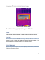
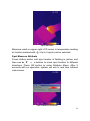
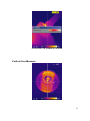
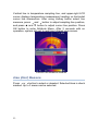
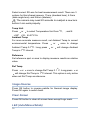
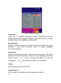
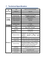
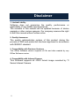
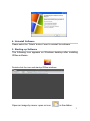
1
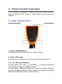
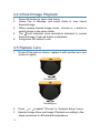
Operation Manual Infrared Camera IR-CAM-160 PLEASE READ THIS MANUAL CAREFULLY BEFORE OPERATION 3, Hagavish st. Israel 58817 Tel: 972 3 5595252, Fax: 972 3 5594529 [email protected] MRC.06.14 To Our Customer Dear Customer: Thank you for choosing this Infrared Camera! Please read this user manual carefully before first use. Also please keep in a safe place for reference in the future. Please operate with the recommended instructions in user manual. We reserve the right to change this user manual without further notice. WARNING DO NOT USE WHEN RAINING! DO NOT OPEN OR EXCHANGE PARTS! REPAIR ONLY CAN BE CONDUCTED BY STUFF! NOTICE In order not to cause malfunction or even damage the device please do not direct the lens towards strong high-temperature radiation source (such as the sun) whether the power is on or off! Avoid violent shock and impact during operation or transport. Storage temperature is between -40OC and 70OC. The device must be kept in original packing case during transport. Typical storage place is cool, dry, ventilated, and without strong electromagnetic field. Keep the lens surface off grease or any chemical substance which would damage the lens. Close the lid after operation. Please regularly backup data on PC to prevent potential data loss and format the internal FLASH memory duly to make it operate properly. Table of Contents 1. 2. 3. 4. 5. Product Summary .................................................. 1 1.1 Standard Item List ................................................ 2 1.2 Optional Item List ................................................. 2 Battery and Charger............................................... 3 2.1 Charging Battery .................................................. 4 2.2 Direct Charging .................................................... 4 2.3 Attention for Using Battery Charger...................... 4 Panel Function Summary ...................................... 5 3.1 Main Control Panel............................................... 5 3.2 Rear Interface Panel ............................................ 6 3.3 Side View ............................................................. 8 Quick Start Reference............................................ 8 4.1 Infrared Image ...................................................... 8 4.2 Measure Target Temperature............................... 9 4.3 Infrared Image and Voice Annotation ................... 9 4.4 Infrared Image Playback .................................... 10 4.5 Replace Lens ..................................................... 10 4.6 Connect to PC .................................................... 11 Operation Menu.................................................... 11 5.1 Display Summary ............................................... 11 5.2 Main Menu ......................................................... 13 5.2.1 File.............................................................. 14 Manage..................................................... 15 Save ......................................................... 17 Format ...................................................... 17 5.2.2 Measure ..................................................... 17 Spot Measure ........................................... 18 Line Measure ............................................ 20 Area (Rect) Measure ................................ 22 Parameters ............................................... 24 Emissivity .............................................. 25 Distance ................................................ 25 Humidity ................................................ 25 Adjust Ratio........................................... 26 i 6. 7. 8. 9. ii Adjust Temp.......................................... 26 Save Setting ............................................. 26 5.2.3 Image ......................................................... 26 Image Setup ............................................. 27 Alarm Switch ......................................... 28 Alarm Temp .......................................... 28 Alarm Color ........................................... 28 Isotherm Color ...................................... 28 Isotherm Temp...................................... 28 Isotherm Width...................................... 28 Screen Display...................................... 29 Analysis Setup .......................................... 29 Temp Range ......................................... 29 IR Lens.................................................. 29 Temp Unit ............................................. 30 Ambient Temp....................................... 30 Reference ............................................. 30 Ref Temp .............................................. 30 Image Reverse ......................................... 30 Clear Screen............................................. 30 L&S (Auto/Manual Mode).......................... 30 5.2.4 Setup .......................................................... 31 System Setup ........................................... 31 Language .............................................. 32 Auto Rectify........................................... 32 Auto Save ............................................. 32 Video..................................................... 32 Transparence........................................ 32 Display Device ...................................... 33 Screen Save ......................................... 33 Power Save........................................... 33 Time & Date.............................................. 33 Factory Default ......................................... 33 Information................................................ 33 Building Thermal Imaging Summary.................. 34 Technical Specification ....................................... 37 Technical Support................................................ 39 Appendix: Emissivity of Raw Material................ 40 1. Product Summary This new generation Infrared Camera (equipped with Uncooled Focal Plan Array Micro-bolometer) produces crisp thermal image and accurate temperature reading to help increase system maintenance quality and efficiency in many industries. This Infrared Camera is packed with advanced features, such as colored thermal image, voice annotation, sound and color alarm, FLASH memory storage, USB connection to PC, and analysis software. Crisp thermal image, accurate temperature reading, clear user interface, reliable product quality, and affordable cost makes this Series Infrared Camera the new standard in Infrared imaging industry! Typical Application: Power Plant: Monitor and diagnose the condition of electrical wire and equipment, detect power leak, and prevent system malfunction Petrochemical Industry: oil pipeline check, material interface detect, heat leakage, insulation structure and power equipment detect. Fire Protection: forest fire protection and latent fire source search, self-ignition prevention and detection of special material, electric fire precaution detect. Medical Application: Accurately measure human body temperature in a distance, critical under a contaminated condition Building Industry: humidity, air leakage and insulation defects detect. Other Applications: Civil engineering, university research, and railway etc. 1 1.1 Standard Item List This Series Infrared Camera comes with the following standard items and accessories: Item Quantity Infrared Camera 1 Li-Ion Battery 2 Battery Charger 1 USB Cable 1 Video Cable 1 User Manual 1 IR Analysis Software CD 1 Suitcase 1 1.2 Optional Item List 2 Wide Angle Lens Telephoto Lens 2. Battery and Charger It is recommended to charge battery immediately when device indicates low power. By press and move in the indicated direction, user can easily insert and remove battery. Battery Insertion Battery Removal Device comes with two sets of Li-Ion battery and one battery charger. It is strongly recommended to operate only with the included battery and charger. Use any other brand charger or Li-Ion battery may cause fire or critical damage. 3 2.1 Charging Battery 1) Following the direction indicated on battery charger, insert the Li-Ion battery, press firmly and push all the way in. 2) During charging, the red LED will be on, and when charging is completed, the green LED will be on instead. : Normally it takes 3 hours to completely charge one battery. 2.2 Direct Charging 1) The battery can also be charged by using an adapter. Normally it takes 5 hours to charge one battery in this mode. 2.3 Attention for Using Battery Charger 1) 2) 3) 4) 5) 4 Battery Charging can only be conducted inside of a house. Do not short-circuit the battery. Do not put the battery in high temperature environment (≥60OC). Never disassemble the battery or put it into fire, which may cause explosion. Do not try to modify the battery or the charger. Please remove the charger from AD socket as soon as charging is completed. 3. Panel Function Summary In this manual, “long press” means Long press button down for about 2 seconds, and “press” or “short press” means press and release. 3.1 Main Control Panel 1. Power ON/OFF Button Long press this button to turn on or off the device. 2. Power LED Light When device is powered on, the Power LED Light will be on. 3, 4, 5, 6. Direction Buttons ( ), 4 direction buttons Up (▲), Down (▼), Left▲ ( ), and Right▼ have different usage in different mode. In main menu, direction buttons are used for moving selected items or changing slide-bar value. In real time Infrared view mode, directions buttons provide one-click access: 5 ▲ Press to freeze Infrared image and press again to unfreeze ▲ to save current Infrared image Long press Press ▲ or ▼ to switch between normal view and 2X zoom After press Hotkey button (refer page 8, 3.3) and in area measure mode: ▲ , and ▼ to move the Select the measure spot; press ▲, ▼, spot in the same direction. Select the measure line and sampling line; press ▲, ▼,▲ , to move the line in the same direction. Select area box: in move menu, press ▲, ▼,▲ , d n a ▼ and ▼ moves area box, and in size menu, press ▲, ▼,▲ ▼ , resizes area box. Select Color Palette or temperature measurement limit: ▲ ▼ , to change, and ▲, ▼ has no effects. Press 7. OK (Menu/Confirm) Button This button has different functions under different conditions: In real time Infrared view mode, press this button opens the main menu. In main menu, press this button to confirm operation. In real time Infrared view mode, long press this button to manually rectify measurement result. In image viewing mode, long press this button to exit. : After auto rectifying, if device has abnormal noise, long press OK button to perform manual rectifying usually solves such issues. 8. MIC Internal MIC records audio annotation. 9. Laser Sight Long press Hotkey button to turn on/off laser sight. 6 3.2 Rear Interface Panel 10. Video Output CVBS standard video output. 11. Audio Output Audio output playbacks recorded voice annotation. 12. USB 2.0 Interface USB2.0 interface transfers data between device and PC. 13. External DC In External DC requirement is 12V. 7 3.3 Side View 14. Hotkey Button Press Hotkey button to switch between Color Palette, area measurement rectangle, temperature limits, and long press Hotkey button to turn on/off laser sight. 15. Sound Alarm Buzzer Signal sound alarm when reaches temperature limit. 4. Quick Start Reference 4.1 Infrared Image 1. 2. 3. 4. 8 Insert Li-Ion battery correctly. Long press Power button until LED light is on and wait until system finishes initialization. Remove IR Lens lid if closed, point to target, and adjust focus to get crisp thermal image. Long press OK button to rectify thermal image. 4.2 Measure Target Temperature 1. Point device to measurement target, and adjust to correct focus. On the upper-right LCD corner, *=×× displays the spot measurement result. For better accuracy, long press OK button to perform manual rectify. 2. Select Area (Rect) Measurement to measure max, min, and average temperature within a rectangle box. ▲ button to freeze thermal image 3. It is recommended to press first, and then apply different and detailed analysis. Press▲ button one more time to unfreeze. 4. Press ▲ button or ▼ button to switch between normal and 2X zoom. Upper-left LCD corner displays ×2 when in 2X zoom. 5. When measure result is outside temperature range, screen display changes to indicate either below or above temperature range. 4.3 Infrared Image and Voice Annotation Each thermal image can save up to 40 seconds voice annotation data. Image and voice annotation can later be reviewed on PC by bundled IR Analysis software. To save Infrared image, first press ▲ button to freeze image, and then long press ▲ button again to open the voice recording menu. If only needs store Infrared image, select Cancel, otherwise select Record. Press OK button to confirm. In main menu, File Save provides the same function. : Select Cancel during voice recording to exit. 9 4.4 Infrared Image Playback 1. 2. 3. 4. 5. Press OK button to open main menu. Select File Manage, and select folder to view stored thermal image. ▲ button or ▼ button to When viewing thermal image, press switch image in the same folder. icon indicates voice annotation attached to current The thermal image. Press ▲ button to playback. Long press OK button to exit. 4.5 Replace Lens 1. Screw off the lens on device, replace it with another lens and screw on tightly. Screwing off Screwing on ▲ or ▼ to adjust “IR Lens” in “Analysis Setup” menu. 2. Press 3. Operate Image Save and Image Playback according to the steps mentioned in 4.3 and 4.4 hereinabove. 10 4.6 Connect to PC Connect device to PC using included USB cable. Refer IR Analysis software manual for additional PC operation instruction. It is recommended to format device periodically. 5. Operation Menu 5.1 Display Summary All items can be selected by short pressing the Hotkey button (Note: Long press Hotkey button will turn on/off laser sight). The selected item is flashing in yellow color. If no operation in 2 seconds after selection, Hotkey mode will exit automatically. Real Time Thermal Image Interface 11 1 Symbol for 2X zoom: symbol 2X denotes enlarge twice in size; press ▲、▼ button to realize the function. 2, 4 Area measure box: 3 areas can be selected in area measure mode. 3 Horizontal measure line: Horizontal sampling line. 5 Temperature unit: there are three options: 、 、K. 6 Battery condition: indicates current battery power condition. 1, 2, 3 and 4 indicates 7 Point measure: temperature value of point 1, 2, 3 and 4 respectively. 8 Line measure: the temperature value in the crossing of measure line and cursor line. 9 Area measure: measure points within the area (maximum, minimum or average temperature is optional) 10 Temperature distribution curve: sample temperature distribution curve of the measure line. 11 Point measure cursor: 4 measure points can be selected. 12 Cursor line: it appears in line measure mode. 13, 15 Lower limit temperature, upper limit temperature: the lower and upper limit temperature of the color code at the same time. 14 Color code: color palette. Any kind of color code is available in the palette. 12 5.2 Main Menu Menu and sub-menu items: Press OK button (when not in Hotkey mode) to enter main menu. Note if press OK button too long, instead of enter main menu, triggers manual rectify. Main Menu Using ▲ and ▼ button to select menu item, and selected item is ▼ button to enter highlighted with white background. Press OK or ▲ sub-menu. Press button to return to previous menu or exit. 13 5.2.1 File Using File menu to save, playback, delete thermal image and voice annotation. File Sub-menu 14 Manage Select Manage to preview thermal image, add or edit voice annotation, or delete thermal image. File Manage Folder is automatically created if not exist when saving thermal image. Folder name is MYYMMDD, and YYMMDD is year, month, and date. For example, Jan 2nd, 2009 folder is M090102. All thermal images taken in this day is saved in this folder. Thermal image file name is Phhmmss, and hhmmss is hour, minute, second (according to system time). For example, P080502 in folder M090102 means the thermal image taken at 08:05:02 time in Jan 2nd, 2009. In File Manage window, press ▲ and ▼ button to select items. ▲ and ▼ Selected item is highlighted with red background. Press button to switch folder or file when highlighted. After select thermal image, press Open to view thermal image or Delete to delete. Press Exit to exit File Manage window. 15 Thermal Image preview Press▲ or▼ button to switch saved thermal image in the same folder. The icon indicates voice annotation data with current thermal image. Long press ▲ button to enter Voice Annotation menu. If voice annotation already exists, press Record will record new voice annotation and erase previously saved one. Press Cancel first to stop recording then press Save to save. Voice Annotation 16 Long press ▼ button to delete thermal image. Delete Saved Thermal Image To exit thermal image playback, long press OK button. Save Save current thermal image. Freeze image first before saving. Format Format the internal FLASH memory. Press OK to confirm or cancel to exit. Format will erase all saved thermal images. It is recommended to transfer data to PC before format. 5.2.2 Measure There are 5 items: Spot, Line, Area (Rect), Parameters, and Save Setting in Measure menu. 17 Measure Sub-menu Spot Measure ▲ or ▼ button to select or deselect. Selected spot is check Press marked. Up to 4 spots can be selected at the same time. Spot Target Selection 18 Spot Measure Measure result on upper-right LCD corner is temperature reading . Up to 4 spots can be selected. at location marked with Spot Measure Attribute Press Hotkey button until spot marker is flashing in yellow, and , buttons to move spot location to different then use ▲, ▼,▲ ▼ directions. Press OK button to enter Attribute Menu. After 2 seconds with no operation, system will exit to real time Infrared view screen. Spot Measure Attribute 19 Emissivity: Refer to Appendix Emissivity of raw materials. Set Reference: Set current spot as reference point. If selected, all measure result will be relative value to this spot temperature. Line Measure There are 2 line measure options: vertical and horizontal. Horizontal Line Measure Horizontal Line Measure Horizontal line is temperature sampling line, and upper-right LCD corner displays temperature measurement reading on vertical cursor line intersection. After using Hotkey button select line measure, press ▲ and ▼ button to adjust sampling line position, and press▲ and▼ button to adjust cursor line position. Press OK button to enter Attribute Menu. After 2 seconds with no operation, system will exit to real time Infrared view screen. 20 Horizontal Line Measure Attribute Vertical Line Measure Vertical Line Measure 21 Vertical line is temperature sampling line, and upper-right LCD corner displays temperature measurement reading on horizontal cursor line intersection. After using Hotkey button select line measure, press▲ and▼ button to adjust sampling line position, and press ▲ and ▼ button to adjust cursor line position. Press OK button to enter Attribute Menu. After 2 seconds with no operation, system will exit to real time Infrared view screen. Vertical Line Measure Attribute Area (Rect) Measure ▲ or ▼ button to select or deselect. Selected Area is check Press marked. Up to 3 areas can be selected. 22 Area (Rect) Target Selection Area (Rect) Measure Measure result on upper-right LCD corner is the temperature measurement result within the corresponding rectangle. There are 3 measure types: max, min, and average temperature. 23 Area (Rect) Measure Attribute Press Hotkey button until area rectangle is flashing in yellow. Press OK button to enter Attribute Menu in which four parameters can be adjusted namely: emissivity, set reference, measure type, move /size. Area (Rect) Measure Attribute Emissivity: Refer to Appendix: Emissivity of raw materials. Set Reference: Set current area as reference. If selected, all measure result will be relative value to this temperature. Measure Type: Select from max, min, and average. Adjust: Adjust rectangle position and size. Parameters Change different settings to adjust temperature measurement accuracy. Press ▲ and ▼ button to select different parameters, ▲ and ▼ button to change value. and press 24 Parameter Sub-menu Emissivity Emissivity varies based on target subject material, surface temperature, surface roughness, measurement angle, and etc. Press▲ or▼ once to change Emissivity by 0.01. Long press▲ ▼ or will change Emissivity in 0.1 intervals. Distance This value can be omitted if target subject is close to device (less than 10m). Otherwise, set Distance value accordingly to get more accurate temperature reading. Press▲ or▼ once to change Distance 0.1m. Long press▲ interval. or▼ will change Distance in 1m Humidity This value can be omitted if target is close to device (less than 10m). Otherwise, set Humidity value according to environmental ▲ or ▼ once to change Humidity 1%. Long press condition. Press ▲ ▼ or will change Humidity in 10% interval. 25 Adjust Ratio Due to long time usage of device, the sensitivity of IR detector may decrease. In such case, it is necessary to adjust ratio value to get more accurate temperature reading. During calibration, if temperature reading is higher than actual target temperature, change ratio value lower, and vise versa. Press▲ or▼ once to change ratio value 0.01. Long press▲ value in 0.1 intervals. or▼ will change ratio Adjust Temp Under certain condition, it is necessary to adjust temperature reading by a pre-define value. Normally this option should be left unchanged. Press▲ or▼ once to change 0.1OC. Long press▲ ▼ or will change this value in 1 OC interval. Save Setting All parameter changes must be saved before power off device. Otherwise, changes will not be saved for next power on. 5.2.3 Image There are 5 items: Image Setup, Analysis Setup, Image Reverse, Clear Screen, and Auto/Manual (L&S) in Image menu. 26 Image Sub-menu Image Setup Image Setup Sub-menu 27 Alarm Switch Press▲ or▼ turns on or off the alarm function. If the Alarm Switch is on, when target subject within area box has surface temperature exceeding Alarm Temp, device will alarm with buzzer sound and mark the high temperature location as Alarm Color if Alarm Color is set. Alarm Temp When Alarm Switch is off, this option is disabled. When Alarm Switch is on, Alarm Temp is the desired alarm temperature. Press ▲ or▼ once to change Alarm Temp 0.1 OC. Long press▲ or ▼ O will change Alarm Temp in 1 C interval. Default setting is 37.0 O C. Alarm Color Alarm Color can select from Auto, Black, White, Red, Orange, Yellow, Green, Blue, Gray, and Purple. Default setting is Auto, which is no color alarm. Isotherm Color When this option is Auto, there is no Isothermal display. Otherwise, target subject Infrared image will change to selected color when temperature is within the range of (Isothermal Temp ± Isothermal Width/2). Default setting is Auto. Isotherm Temp Press▲ or▼ once to change Isothermal Temp 0.1OC. Long press▲ or▼ will change Isothermal Temp in 1OC interval. Default setting is 37.0OC. Isotherm Width Adjust Isothermal Width to change the range of Isothermal Color display. Press▲ or▼ once to change Isothermal Width 0.1OC. 28 ▲ or▼ will change Isothermal Width in 1OC interval. Long press Default setting is 1.0OC. Screen Display When this option is Off, screen display will clear battery condition, ▲ or temperature unit, temperature limit, and color palette. Press ▼ to turn on/ off this option. Analysis Setup Analysis Setup Sub-menu Temp Range Select Temperature range base on measure target temperature from 3 options: standard grade (-20/120OC) and medium grade (0/350OC) and extra grade (350/1200OC) which is customized. IR Lens 29 Select correct IR Lens for best measurement result. There are 3 options for this infrared camera: 11mm (standard lens), 6.3mm (wide angle lens), and 54mm (telelens). : The camera may need 20 seconds to readjust a new lens before it can work properly. Temp Unit ▲ or ▼ to select Temperature Unit from OC, Press =9/5* +32,K=273.15+ Ambient Temp , and K. For more accurate measure result, set Ambient Temp to correct environmental temperature. Press▲ or▼ once to change Ambient Temp 0.1OC. Long press▲ Temp in 1OC interval. or▼ will change Ambient Reference Set reference spot or area to display measure results as relative value. Ref Temp ▲ Press ▼ or ▲ once to change Ref Temp 0.1OC. Long press or ▼ will change Ref Temp in 1 C interval. This option is only active when set Ref Temp as reference. O Image Reverse Press OK button to reverse palette for thermal image display. Press OK again to switch back. Clear Screen Press OK button to clear all screen items except Logo mark. L&S (Auto/Manual Mode) 30 Press OK button to switch between auto and manual rectifying. In manual rectifying mode, upper-left corner of LCD display shows L&S. 5.2.4 Setup There are 4 items in Setup menu: System Setup, Time & Date, Factory Default, and Information. Setup Sub-menu System Setup System Setup includes: Language, Auto Rectify, Auto Save, Video, Transparence, Display Device, Screen Save, and Power Save. Press ▲ and ▼ button to switch selection, and press▲ and▼ button to adjust value. Active item is highlighted with red background. 31 System Setup Sub-menu Language There are 11 different language options: Simplified Chinese, Traditional Chinese, English, Korean, Japanese, German, French, Russian, Italian, Portuguese and Spanish. Auto Rectify Set the number of seconds to perform next auto-rectify. Set value between 1 and 3000 seconds. Value 0 means disabling auto-rectify feature. Auto Save Set the number of seconds to perform next auto-save. Set value between 5 to 3600 seconds. Value 0 means disabling auto-save feature. Press▲ or▼ once to change the value by 1 second. ▲ Long press ▼ or will change the value in 10 intervals. Video Select between PAL and NTSC. Transparence Set to enable or disable menu transparence feature. 32 Display Device Select between LCD display and external monitor device. Only one video output device can be selected at one time, the other one will be disabled. : If accidentally selected external monitor device and LCD display is disabled, power off and power on device to get LCD display back. Screen Save Set the number of minutes without operation to trigger disabling LCD display to save power. Select between 5min, 10min, 30min, and None. Power Save Set the number of minutes without operation to trigger power off completely. Select between 10min, 20min, 30min, and None. Time & Date Set system date and time. Press ▲ or ▼ button to select an item, ▲ or ▼ button to change its value and press OK button to press confirm. If Li-Ion battery is removed for a long time, it is necessary to reset system time and date. Factory Default Restore factory default and rectify some improper settings. Information Select to display system information, such as: serial number, software version, and production date etc. 33 6. Building Thermal Imaging Summary As the quality of life improves and the low-carbon life style becomes known, higher demands are being set on buildings. The features of our IR camera make it possible to detect slight temperature difference and to analyze indoor humidity and leakage. Hereinafter are images in some cases. The effect drawing of building detection The effect drawing of indoor humidity 34 The effect drawing of indoor water leakage The effect drawing of indoor corner air leakage 35 The effect drawing of outdoor corner air leakage 36 7. Technical Specification IR Detector Type New UFPA micro-bolometer Resolution 160×120 Pixel Spacing 25μm Standard Lens Spatial Resolution 21°×16°/0.15m Wide-angle 35°×27°/0.05m telelens 4°×3°/0.8m 2.3mrad( standard lens) Thermal Sensitivity <60mk at 30℃ Frame-frequency 50/60Hz Focusing Manual Optional Lens Infrared Image Quality Display Digital Zoom 2X Spectral Range 8~14μm LCD Temperature Range 3.5" Color LCD -20℃~+120℃/ 0℃~+350℃ Up to 1200 ℃optional) ±2 or ±2%(reading range), select the bigger value Accuracy Measure rectification Measure Mode Color Palette Auto/Manual 4 spots, 3 areas available under real time mode(max, min and average temp) line measure, isothermal display, temp difference measure and temp alarm (sound/color) 12 Colors selectable (including iron red, rainbow, black-white, and white-black etc.) Image Setup Auto/Manual adjust contrast, brightness System Setup Date, Time, Temperature Unit ℃/℉/K 10 Languages available, namely: Chinese (simplified & traditional), English, Italian, Japanese, Russian, French, German, Korean, Spanish and Portuguese. Measure Emissivity Rectification Ambient Temp Rectification Atmospheric Trans Correction Adjustable from 0.01 to 1.0 Auto, according to background temperature input Auto, according to distance, relative humidity, ambient temperature input Continued table: Technical Specification Storage Laser Power Supply Operating Condition Storage Media (Built-in Memory) Up to over 1500 images Storage Mode Auto/Manual single frame image storage File Type JPEG, with 14 bits measure data Voice Annotation 40 Seconds voice recording per image (built-in microphone) Director Class 2, 1mW/635nm Red Battery Type Rechargeable Li-Ion Battery Battery Operating Time 3 Hours (Under normal temperature) Charging type Intelligent charger Power Save Included External Power 12V±5% DC Operation Temperature Storage Temperature -20 ℃ +50℃ -40℃~ +70℃ Humidity ≤90% (non condensing) Protection Grade IP54 Shock 25G IEC68-2-29 Vibration 2G IEC68-2-26 Weight ≤780g(Include battery and lens) Size (L×W×H) 330mm×95mm×86mm Physical 38 8. Technical Support For common mistakes and issues during operation, please refer the following form. If issue cannot be resolved, please contact our technical support department. For simple problems arising during operation, please refer to the following table. If the problem cannot be settled, please cut off the power and contact our technical department. Problem Cause and Solution Camera cannot be powered on Device power off automatically Battery power is soon used up No thermal image Thermal image is black and white No battery or batteries are not installed correctly → Install battery correctly. Battery power is used up. → Change battery or recharge. Save power mode →power on after 5 seconds. Battery power is used up. → Change battery. Ambient temperature is too high or low. Battery is not fully charged. → recharge battery fully. Battery may already reach end of life. (300 usage cycles) → use new battery to charge. Lens lid is closed. → Remove lens lid. Black & white palette may be selected. →restore factory default. 39 9. Appendix: Emissivity of Raw Material (For reference purpose only) Material O Surface Temp ( C) Emissivity (ε) inoxidized 100 0.20 Oxidized Brown polished 100 20 0.55 0.40 Unpolished Oxidized Oxidized badly Oxidized 38 100 20 100 0.22 0.61 0.78 0.74 Rusted Oxidized 25 200 0.65 0.64 inoxidized Rough 100 25 0.21 0.94 Polished Oxidized 38 200 0.28 0.37 Oxidized 60 0.85 Oxidized 200 0.79 Brick Concrete --- 20 20 0.93 0.92 Glass Smooth flat White 20 100 0.94 0.92 Natural Black 100 0.97 Smoky black 25 0.95 Candle smoke Black-lead rough 16 Color average White -Polished -Human Fine Rough 20 20 100 20 20 30 30 32 21 21 0.95 0.98 0.94 0.93 0.90 0.90 0.96 0.98 0.90 0.93 Aluminum Brass Copper Iron Cast Iron Wrought Iron Nickel Stainless Steel Steel Lacquer Carbon Paint Paper Soil Wood Water Skin China 40 800 Uncooled Focal Plane Infrared Cameras IRSee Report Software User Manual Table of Content Ⅰ. Software Installation................................................................... 1 1. Introduction ...........................................................................1 2. System Requirements...........................................................1 2.1 Hardware Configuration ................................................1 2.2 Operating System .........................................................1 3. Software Installation..............................................................1 4. Uninstall Software.......................................................................... 3 5. Start Software .......................................................................3 Ⅱ. Function Description .................................................................. 4 1. Image Import and Export ................................................... 4 1.1 Image Import................................................................. 4 1.2 Image Export................................................................. 5 2. Modules ................................................................................ 5 2.1 Ribbon........................................................................... 6 2.2 Measuring Temperature Zone..................................... 13 2.3 Histogram Area ........................................................... 20 2.4 Line Profile Measurement Area................................... 22 2.5 Color Code Area ......................................................... 23 2.6 Label Area................................................................... 25 2.7 Visible Light................................................................. 26 i Disclaimer 1. Limited Liability Software does not guarantee the quality, performance or applicability of any hidden special purpose. The contents of this manual will be updated because of device upgrade or other various reasons. Our company reserves the right to edit this manual without further notice. 2. Quality Assurance The quality administration system of this product during the process of R&D and production has been approved in accordance with ISO9001 standard. 3. Compatibility with Previous Versions This IRSee Software version supports all file and data created by any IRSee Software version. 4. Compatibility with Infrared Camera This Software supports all JPEG format image recorded by TI Series Infrared Camera. ii Ⅰ. Software Installation Welcome to Use IRSee software. 1. Introduction The IRSee Report version has a friendly user interface, 4 methods for measure analysis, and the function to save analysis report in Word, PDF, Excel and other formats. 2. System Requirements The files of the IRSee software consist of IR image, visual image and graphic file, all of which are far bigger than normal text files, thus the following standards of the computer hardware configuration should be met: 2.1 Hardware Requirements CPU PENTIUM ® Dual-Core 2.0GHz processor or faster. 1Gbytes or more system memory. 20G or bigger hard disk. 1440×900 or higher resolution screen. 2.2 Operating System IRSee Software is compatible with Microsoft Windows 2000, XP, Vista, Windows 7. It provides a multi-language version for users. 3. Software Installation The instructions of IRSee software installation and necessary precautions before using this software will be given in detail hereinafter: Please follow the instructions when installing IRSee software application. Place software CD-ROM into CD drive, and run setup.exe in the CD root directory. The default route is C:\Program Files \IRSee Report. You can change directory when installing. Note: The software to operating and install in administrator on the Vista/Win7. 1 Step A: Running the Setup.exe, the system indicates the installation path, please adjust or change as needed. Step B: Click the Next button to access the software installation. Step C: Click the Next button continuously until the software installation is completed. The system will enter the decoder installation automatically. Step D: Click and follow the default installation settings until the installation is completed. 2 4. Uninstall Software Please select the “Delete” button if want to reinstall the software. 5. Starting-up Software The following icon appears on Windows desktop after installing IRSee software. Double-click the icon and startup IRSee interface. Open an image by menu: open or icon in the ribbon. 3 Note: IRSee software has 10 different working languages, namely: Chinese (simplified & traditional), English, Italian, Japanese, Russian, French, German, Korean, Spanish and Portuguese. IRSee software has auto-recognition language function with the operating system in PC, the IRSee will be in English version if the operating system is beyond mentioned languages in PC. Ⅱ. Function Description 1. Image Import and Export 1.1 Image Import ◆Method 1: 4 Click the software icon on upper left corner to pop up the menu. Click the Open button (also available to select a recently opened image path in the image bar) to pop up the file selection dialog box. Select a file in the file selection dialog box (single or multiple selections available). ◆Method 2: Click the “Open” button in the ribbon. 1.2 Image Export It is available to export in accordance with the following methods after importing images: ◆ Method 1: Click the button “Save Picture As” button on the software icon on the upper left corner to pop up a file selection dialog box. Select / a file path and save the image in the current active window. ◆Method 2: Click the property analysis in toolbar. Click the button “Save picture As button to pop up a file selection dialog box. Select / a file path and save the image in the current active window. ◆Method 3: Click the software icon on the top left corner. Click the button“Save current picture” to save the modified image on the current active window. ◆Method 4: Click the property analysis in Ribbon. Click the button “Save current picture” to save the modified image on the current active window. 2. Modules As displayed on the software interface, the software has the follows: the Quick Access Toolbar, Ribbon, Measuring Temperature Zone, Histogram Area, Line Profile Measurement Area, Color Code Area, Label Area, and Visible Area. 5 2.1 Ribbon The Ribbon is composed of File, Parameters, Audio, Temperature Type Settings, Report Wizard, USB, Panel and Language. 2.1.1 File 2.1.1.1 Open Click the File button to pop up a file selection dialog box. Select and open a file to be analyzed in the dialog box. 2.1.1.2 Save Method 1: Click the “Save current image ”button to pop up a file selection dialog box. Set / select the file path name where the file is saved. Save the image in the current active window. Method 2: Click the File and select the save all the modified images. “Save all images ” button to 2.1.2 Set 2.1.2.1 Emissivity adjustment 6 Method 1: Please input a required emissivity value (1-100) in the Emissivity edit box. Press the Enter key to confirm it. Method 2: Click the Up and Down keys in the edit box to adjust and set an emissivity value. 2.1.2.2 Humidity Adjustment ●Please input a required humidity value (1-100) in the humidity edit box. ●Press the Enter key to confirm. 2.1.2.3 Distance Adjustment ●Please input a required distance value (1-1000, unit: meter) in the distance edit box. ●Press the Enter key to confirm. 2.1.2.4 Ambient Temperature Select the option to show the actual ambient temperature while the thermal image is being shot. 2.1.2.5 Dew Point Temperature Select the option to show the dew point temperature. 2.1.2.6 Cancel Changes Click the “Return to default settings ” button to recover the emissivity, humidity, ambient temperature, or distance to its original state. 2.1.3 Audio When analyzing thermal images with voice information, buttons in audio section would be effective and show in green, you can replay the voice saved with the image by clicking corresponding buttons. Otherwise the buttons would show in gray and cannot be operated. 2.1.4 Set Temperature Type This option is used to set the temperature display unit, click ℃, ℉ or K to set the temperature unit to Celsius, Fahrenheit or Kelvin respectively. 7 2.1.5 Report Wizard 2.1.5.1 Report Wizard Report Wizard is used for creating a report, the Report Edit is mainly used for editing a report for further analysis. Click the Report Wizard to select the type of exported report as needed. Click Next to select an image or multiple images. Fill in related information in accordance with different types of report templates ->> Preview 8 After necessary information completed, you can click the“save”button to save the report as needed. All reports have the same format of “.HX”, and repots can be edited again in IRSee software. 9 10 2.1.5.2 Edit Report If a report is to be closed, the system will prompt whether to save the report or not. Click the OK button. Input and select the saving path and file name, and then click the Save button. Click the report in Ribbon ->> Edit Report 11 Select a saved report to reopen and edit it. 2.1.6 USB Direct-Transmission (only for device with Direct-Transmission function) 2.1.6.1 Connection Click the Ribbon Settings ->> USB Direct-Trans Connect a device, set to USB Direct-Trans mode for the device. Click the device iron on PC software interface ->> Open the device ->> Play 2.1.6.2 Video Click the device ->> Record Select a video path ->> Input the name of the video file. 2.1.6.3 Stop the video Click File ->> Stop Recording 12 2.1.6.4 Pause, Stop and Close Direct-trans Click the Pause, Stop and Close buttons under the File menu respectively to stop the current operation. 2.1.6.5 Print Screen Click the Print Screen button and save the printed image into the Picture folder under the installation directory, and name it by a time format. 2.1.7 Panel It is mainly used for showing/ hiding each area, a user can adjust the size and position of each display area as needed, and then click the “Save Settings” to save the current settings, and click the “Return to defafult settings” to recover. 2.2 Measuring Temperature Zone The functional options in measuring area are shown below: 13 The measurement objects can analyze the thermal images by the following three kinds of analysis methods: point, line, and area. Line measurement analysis has four types: arbitrary line, horizontal line, vertical line and multiple-line analysis. Area measurement analysis has below: rectangular, elliptical and polygonal analysis. The system can analyze up to 20 spots objects, 10 lines analysis object, 20 area analysis objects, 10 polygonal objects and 10 elliptical objects simultaneously. 2.2.1 Select Measured Objects The prior sequence of object selection is point, line, and area. ● When two or more objects are simultaneously selected, the system can operate in accordance with the above prioritization. e.g.: if both a point object and a line object are simultaneously selected, the point is more prior than line, the point object will be prior selected; If both an area object and a line object are simultaneously selected, the line is more prior than the area; the line object will be prior selected. ● 14 If two or more areas are simultaneously selected, the smaller area will prevail. e.g.: If Rectangle 1 and Rectangle 2 are simultaneously selected, Rectangle 1 is smaller than Rectangle 2, Rectangle 1 will prevail. 2.2.2 Point Analysis Create a point Click the button Move the mouse to a point to be analyzed, and click it. Move a point Move the mouse to a point to be moved. When the mouse status changes to point. Move the mouse. , left-click to select the Delete a point Select a measurement point to be deleted. Click the button to delete selected Measured Objects. 2.2.3 Line Analysis Create a line Arbitrary line Click the Arbitrary Line button. Click the Set a starting point of the line in the thermal image to be analyzed. Left-hold and drag the mouse to the terminal point of the line. Create button to pop-up a menu. 15 Vertical Line Click the Create button to pop-up a menu. Vertical Line button. Click the Set the vertical coordinates of starting point of the line in the thermal image to be analyzed. Left-hold and drag the mouse to the vertical coordinates of terminal point of the line. Horizontal Line Click the Horizontal Line button. Click the Set the horizontal coordinates of starting point of the line in the thermal image to be analyzed. Left-hold and drag the mouse to the horizontal coordinates of terminal point of the line. Create button to pop-up a menu. Move and change a line Move Move the mouse to the position of a line to be moved. When the state of mouse becomes , left-click to select it. And then move it. Change the positions of starting point / terminal point Move the mouse to the position of the line to be moved. 16 When the state of mouse becomes , left-click to select the line. Move the mouse to the position of starting point / terminal point to be moved. When the state of mouse becomes , left-click to select starting point / terminal point. Drag the mouse to the required position of starting point / terminal point. Delete a line Select the line measurement object to be deleted. Click the button to delete selected Measured Objects 2.2.4 Area Analysis It has three areas: rectangle, polygon, and ellipse. Create a rectangle ●Click the Create Area button to pop up a menu. ●Click the Rectangle . ●Select the starting point of the rectangle in the thermal image to be analyzed. ●Drag the mouse to create a rectangular analysis area. Move and Drag a Rectangle Move Move the mouse into the rectangle target area. When the state of mouse becomes , click to select it. Move the mouse. Zoom in / out Move the mouse into the rectangle to be modified. When the state of mouse becomes , click to select it. Move the mouse to the eight vertexes of the rectangle. When the state of mouse becomes , click to select it. Move the mouse to change the size of the rectangle. 17 Delete a rectangle ●Select the rectangle object to be deleted. ●Click the a polygon Click the button to delete selected Measured Objects Create Create Polygon to pop-up a menu. Click the Polygon . Select the starting point of the polygon in the thermal image to be analyzed. Move the mouse and left-click to add other vertices of polygon. Right-click to stop adding the vertexes to create a polygon. If the number of vertexes is equal to or more than 50, the system can stop adding automatically. Move and Drag a Polygon Move Move the mouse into the polygon to be analyzed. When the state of mouse becomes , click to select it. Move the mouse. Zoom in / out Move the mouse into the polygon to be modified. When the state of mouse becomes , click to select it. Move the mouse to a vertex to be modified. When the state of mouse becomes , click to select it. Move the mouse to change the position of the vertex, thus to modify the polygon. Delete a Polygon Select the polygon to be deleted. Click the 18 button to delete selected Measured Objects Add an ellipse ● Click the ● Click the Ellipse . Select the starting point of the ellipse in the thermal image to be analyzed. Drag the mouse to create an elliptical analysis area. ● ● Add Area button to pop-up a menu. Move and Drag an Ellipse Move Move the mouse into the ellipse to be moved. When the state of mouse becomes , click to select it. Move the mouse. Zoom in / out Move the mouse into the ellipse to be modified. When the state of mouse becomes , click to select it. Move the mouse to the eight vertexes. When the state of mouse becomes , click to select it. Move the mouse to change the size of the ellipse. Delete an ellipse Select the ellipse to be deleted. Click the button to delete selected Measured Objects 2.2.5 Save Images Click the box. Save Images button to pop up the file selection dialog 19 Select image formats Select / set the file path. Click the Save button to save the image . 2.2.6 Clear measured objects Click the Clear Measured Objects button to clear all point, line, area analysis of measured targets. 2.2.7 PIP / Infrared( only for visible image ) Click the button to switch between the PIP and infrared modes. 2.2.8 Export Temperature Data Click the button to export all the points’ temperature in the whole thermal image to TXT file, the temperature unit is Celsius. 2.3 Histogram Area 2.3.1 Relative / absolute Scale If the relative scale is selected, the vertical axis represents the percentage of the number of measured points; if the absolute scale is 20 selected, the vertical axis represents the actual number of corresponding measured points. It is available to click the button to switch. 2.3.2 Gradient / Solid Color Display If the gradient histogram display mode is enabled, the system can automatically select corresponding color to fill the histogram in accordance with the temperature; If the solid color display mode is enabled, the system will fill histogram with red. it is available to click the button to switch. 2.3.3 Enable /Disenable Grid If the grid is enabled, it is available to draw grid dashed lines on the histogram background; if disenabled, it’s unavailable to draw. it is available to click the button to switch. 2.3.4 Save a Histogram Click the Save Images button to pop up the file selection dialog box. Select the image format. Check / set the path to save the image. Click the Save button to save the current histogram. 2.3.5 Set the Background Color Click the Set Background Color button to pop-up color selection dialog box. Select a background color. Click the OK button to confirm the background color. 21 2.3.6 Show / Hide the Out-of-Range Column Click the button to show or hide any column out of temperature range of color code bar, composed of points. 2.3.7 Reset Click the Reset button to reload the default state to the histogram. 2.4 Line Profile Measurement Area 2.4.1 Show /hide grid lines Click the Grid button to switch the grid display and hide mode. 2.4.2 Set the background color 22 Click the background color button to pop-up color selection dialog box. Select a background color. Click the OK button to confirm the background color. 2.4.3 Save the line profile measurement image ● ● ● ● Click the button to pop up the file selection dialog box. Select an image format. Check / set the path to save the image. Click the Save button to save the line profile measurement image. 2.5 Color Code Area It is available to adjust the type of color code, 12 kinds of color bars are available. A User can also adjust the maximum or minimum temperature, and isothermal upper and lower limits, any out-of-range temperature can not be supported. If the dew point is selected, the corresponding color code of below the dew point temperature will be unified. 2.5.1 Default maximum or minimum temperature and upper and lower limits of isothermal color Click the button to reload default settings. 2.5.2 Adjust upper and lower temperature Method 1: Move the mouse to the upper and lower temperature on left side of the color bar ; When the mouse’s status turns , please left-click to select; 23 Drag the mouse to the required temperature value position. Method 2: Click the scroll bar on the arrow button to adjust upper and lower temperature (each step is 0.1) 2.5.3 Adjust upper and lower limits of isothermal color, If the isothermal color is enabled, a user can adjust the isothermal scope Method 1: Move the mouse to the upper and lower temperature on right side of the color bar. , please left-click to select. When the mouse’s status turns Drag the mouse to the required temperature value position. Method 2: Click the scroll bar on the arrow button to adjust upper and lower limits (each step is 0.1). 2.5.4 Select a dew point When a dew point is selected, all points which temperature is below the dew point will be colored in uniform. 2.5.5 Set isothermal color and dew point color The default isothermal color is fluorescent green, the default dew point color is blue, and the dew point is prior selected. ● Click the Set Color button, to pop up the color selection dialog box. ●Select / customize the background color. ●Click the OK button to confirm the selected color. 24 2.6 Label Area The Label Area indicates detailed information of measured objects, when the measured object changes, the object's label will change accordingly, the structure of label area is as below: 2.6.1 Set the color of measured object Select a measured object in the label list. Click the button to set a color for currently selected object. Select / customize a color. Click the OK button to conform the color of measured object. 2.6.2 Add remarks for measured object Select a measured object in the label list. Add Remarks in the Remarks edit box (0-512 characters available). Click the Upload Current Settings button to add remarks. 2.6.3 Change emissivity of measured object ● ● Select a measured object in the label list. Adjust the scroll bar of emissivity. 2.6.4 Remove a measured object ● Select a measured object in the label list. ● Click the button to delete the currently selected object. 25 2.6.5 Add detailed Information in Image remarks If any object in the label is not selected, it is available to input information. 2.7 Visible Light 2.7.1 Open an Image Click the Open button to pop up the file selection dialog box. Select a file to be added from the dialog box. ● ● 2.7.2 Save an image Click the Save button to pop up the file selection dialog box. Select an image format. Check / set the path where the image is saved. Save the visible light image. ● ● ● ● 26 2.7.3 Delete an image Click the Delete button to delete the currently added visible image. 2.7.4 Flip an image Click the or counterclockwise. button to flip an image clockwise or 2.7.5 PIP This feature is available for any image that with visible light. Click the button to set an image. 27 Set the transparency Drag the lower left progress bar to adjust the PIP values between infrared image and visible image. ● Set infrared display range Drag the right two progress bars to adjust the infrared display range of interval or above upper or below lower limit. ● Click the “OK” button to save the file, the updated image is displayed on the measurement area. 28