1
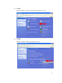
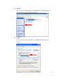
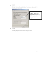
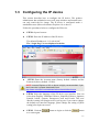
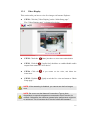
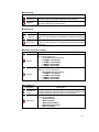
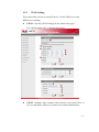
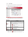
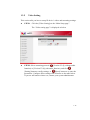
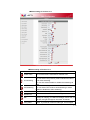
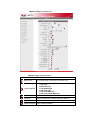
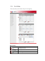
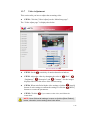
Encoder Firmware – D1
A1D-M2N-V2.06.12-AC
User’s Manual
Table of Contents
1.
INSTALLATION _______________________________________________ 1-1
1.1
Minimum System Requirements ___________________________________ 1-1
1.2
Preparation before setup _________________________________________ 1-2
1.2.1
1.3
Setup your PC network ________________________________________________ 1-2
Configuring the IP device_________________________________________ 1-7
1.3.1
Video Display _______________________________________________________ 1-9
1.3.2
Host Setting ________________________________________________________ 1-10
1.3.3
WAN Setting _______________________________________________________ 1-13
1.3.4
Date Setting ________________________________________________________ 1-16
1.3.5
Video Setting _______________________________________________________ 1-18
1.3.6
Event Setting _______________________________________________________ 1-24
1.3.7
Video Adjustment ___________________________________________________ 1-26
1.3.8
User Account Management ____________________________________________ 1-28
1.3.9
System Info ________________________________________________________ 1-29
1.3.10
Firmware Upgrade ________________________________________________ 1-31
1.3.11
Factory Default ___________________________________________________ 1-33
1.3.12
Save Reboot _____________________________________________________ 1-34
1.3.13
Logout__________________________________________________________ 1-35
i
1
INSTALLATION
1.
1.1
Minimum System Requirements
CPU
Pentinum 4 2.4GHz and above
Hard Disk
40 GB or above
Memory
256 MB or above
Operating System
Windows XP with SP2 or above / Windows 2000 with SP4 or
above
Video Resolution
SVGA or XGA with 1024x768 resolution
1-1
1.2
Preparation before setup
To configure your IP device, you have to use the Internet Explorer to login.
Before that, your PC’s networks settings and the IP device’s IP address
must be setup. Make sure all the connections are connected correctly, and
then follow the procedures below to setup.
1.
Setup your PC network
You have to match your PC’s TCP/IP setting with the IP device’s
default settings before you can use IE browser to login it. This section
tells you how to setup your PC’s TCP/IP settings.
2.
Setup IP device’s IP address
This IP device’s IP address can be setup manually or automatically by
network service (DHCP). If it acquires the IP address by using the
DHCP service, please use the IP utility software bundled in the product
CD to search all the IP devices’ IP address.
1.2.1
Setup your PC network
To set up the network of IP device via a PC, you have to change the TCP/IP
settings of the PC.
The following are the default network settings of IP device.
IP Address: 192.168.0.100
Subnet Mask: 255.255.255.0
To access the IP device, the IP address of the PC should match the address
below.
IP Address: 192.168.0.xxx
Subnet Mask: 255.255.255.0
NOTE: xxx should be a number from 1 to 254, but 100 is excepted.
1-2
The procedures below is the setup procedure of a PC using Windows XP as
its OS. When running an OS other than Windows XP, please refer to the
manual included with the OS.
z
STEP1
Start up your PC.
z
STEP2
Click the [Start] and select the "Control Panel"
1-3
z
STEP3
Double-click the "Network and Internet connections" icon.
z
STEP4
Double-click the "Network connections" icon
1-4
z
STEP5
Click “Local Area Connections”, and then click “Change settings of
this connection” in the network Task menu.
z
STEP6
Click “Internet Protocol (TCP/IP)”, and then click the [Properties]
button.
1-5
z
STEP7
Click the “Use the following IP address” radio button and enter the IP
address and the subnet mask.
Please set the settings as below.
IP address: 192.168. 0.xxx
Subnet mask: 255.255.255.
0
(NOTE: xxx should be a number
from 1 to 254, but 100 is
excepted.)
z
STEP8
Click the [OK] button and the window dialog box closes.
1-6
1.3
Configuring the IP device
This section describes how to configure the IP device. The product
administrator has unlimited access to all setup windows and normal users
can only watch the live image. The IP device is configured under a
standard browser (Microsoft Internet Explorer 6.0 or above).
Follow the procedures below to configure the IP device.
z
STEP1: Open a browser
z
STEP2: Enter the IP address of the IP device.
The default IP address is “192.168.0.100”
The “Login Page” is now displayed as below.
z
STEP3: Enter the Account name (factory default: Admin) and the
Password (factory default: 123456).
NOTE: Internet Explorer of 6.0 or above is highly recommended. If you
don’t have the it, please download it from
http://www.microsoft.com/windows/ie/downloads/default.mspx
z
STEP4: Select the language of the IP device user interface. You can
select from English, Traditional Chinese, Simplified Chinese, Japanese,
Spanish, Italian, German, Portuguese,Czech and French. This user
interface setting will disappear once you log out, if you want to change
the default user interface language, please change the setting of [Host
setting] after login successed.
z
STEP5: Click the
to re-enter again.
button to login or click the
button
1-7
Once successfully login, the “Main Setup page” will be displayed as
below.
1-8
1.3.1
Video Display
This section tells you how to view live images via Internet Explorer.
z
STEP1: Click the [Video Display] on the “Main Setup page”.
The “Video Display page” is displayed as below.
z
STEP2: Check the
z
STEP3: Click the
[Audio Out] checkbox to enable/disable audio
output from control PC to IP device.
z
STEP4: Click the
[Mute] checkbox to select mute enable/disable
if you cannot see the video, and follow the
instructions.
z
STEP5: Click the
Setup page”.
[Quit] to exit the live view and return to “Main
NOTE: If the streaming is disabled, you cannot see the live images
here.
NOTE: Be sure to set the Network Connections Type to Auto
Negotiation to respective apparatus connected to this IP device via
network. Otherwise, the maximum transmission performance might not
be achieved. This is because the IP device follows MII standard.
1-9
1.3.2
Host Setting
This section tells you how to setup IP device’s host settings and LAN
settings.
z
STEP1: Click the [Host Setting] on the “Main Setup page”.
The “Host setting page” is displayed as below.
z
STEP2: Configure these settings with reference to the table below. If
you are still unsure what to set, contact your system administrator.
1-10
■Host Setting
Parameters
Host name
Language
Description
Enter a host name, and this host name will be shown when you
use the IP utility or the SDK to search for the IP device.
Select the language of default user-interface. Each user login
will see the default user-interface first.
■LAN Setting
Parameters
IP address
Subnet mask
Description
The address shown is the current LAN port IP address of this IP
device. You can change its IP address by change the parameter
here.
The address shown is the current LAN port subnet mask of this
IP device. If the IP address is changed, adjust the subnet mask
accordingly..
■Network link speed & duplex
Parameters
LAN port
WAN port
Description
This item lets you select the network transmission speed of LAN
port. You can select from
1. Auto detect (default setting)
2. 100Mbps / Full duplex
3. 100Mbps / Half duplex
4. 10Mbps / Full duplex
5. 10Mbps / Half duplex
This item lets you select the network transmission speed of
WAN port. You can select from
1. Auto detect (default setting)
2. 100Mbps / Full duplex
3. 100Mbps / Half duplex
4. 10Mbps / Full duplex
5. 10Mbps / Half duplex
■Port Mapping
Parameters
TOS (type of
service)
TOS priority
Description
Select whether to add the TOS tag onto the streaming data.
Streaming data with a higher priority TOS tag will be transmitted
first while compared with other data to be transmitted.
Select the TOS tag’s priority to be added onto the streaming.
You can select between
1. Normal-Service
2. Minimize-Cost
3. Maximize-Reliability
4. Maximize-throughout
5. Minimize-Delay
1-11
■ToS (Type of Service)
Parameters
Description
HTTP port
Select the port for this IP device to use HTTP protocol.
Search server
port1
Search server
port2
Select the port1 for this IP device to support search function of
the application program (eg. IP utility).
Select the port2 for this IP device to support search function of
the application program (eg. IP utility).
STEP3: Click the
[Apply] button of each setting to confirm the
settings or click the
[Reset] button to re-enter the parameters.
z
NOTE: Once finished all settings, be sure to click the [Save Reboot]
button, otherwise, some settings won’t take effect.
NOTE: Check with your system administrator, if Client PC and IP device
are setting in different VLANs, please connect to WAN port.
NOTE: Be sure to set the Network Connections Type to Auto
Negotiation to respective apparatus connected to this IP device via
network. Otherwise, the maximum transmission performance might not
be achieved. This is because the IP device follows MII standard.
1-12
1.3.3
WAN Setting
This section tells you how to setup IP device’s WAN, DNS server and
DDNS server settings.
z
STEP1: Click the [WAN Setting] on the “Main Setup page”.
The “WAN setting page” is displayed as below
z
STEP2: Configure these settings with reference to the table below. If
you are still unsure what to set, contact your system administrator.
1-13
■WAN Setting
Parameters
Failover
Dynamic IP
address
Description
The LAN and WAN in IP device are binned to one single IP
configuration. All streaming traffics go through WAN by default. The
LAN will take over WAN's function when the WAN is linked down. As
WAN is recovered, LAN release the streaming function to WAN.
Click this to enable IP device’s DHCP function.
It will acquire its WAN port IP address from a DHCP server
within the same network. (You must have a DHCP server in
order to enable this function.)
Click this to manually enter the IP device WAN port IP
address.
IP address: Enter the WAN port IP address.
Static IP
Subnet mask: Enter the subnet mask of WAN port. If
IP address is changed, adjust the subnet mask
accordingly.
address
ISP gateway: Enter the IP address of the gateway
(the router).
Click this when you connect IP device directly to the xDSL
modem.
User name: Enter the user name of your xDSL
account.
PPPoE
Password: Enter the password of your xDSL
account.
Note: You have to click the [Save Reboot] after you click the
[Apply button] to let this IP device start xDSL connections.
■DNS server Setting
Parameters
Primary DNS
server
Secondary DNS
server
Description
Defines the IP address of the primary DNS server. This is used
for identifying this computer by name instead of IP address.
The IP address of the secondary DNS server. It will be used
once the primary DNS server fails.
■DDNS server Setting
Parameters
DDNS type
Service ISP
Host name
Description
Click this to enable IP device’s DDNS function.
DDNS function enables user to connect to this IP device by
domain name even if its IP address is not static.
Click one of the DDNS service providers.
You can visit their website to get a DDNS service account for
this IP device.
Enter the host name of your DDNS service account. (ex:
xxxx.dyndns.org)
1-14
z
User name
Enter the user name to login your DDNS service account.
Password
Enter the password to login your DDNS service account.
STEP3: Click the
[Apply] button of each setting to confirm the
settings or click the
[Reset] button to re-enter the parameters.
NOTE: Check with your system administrator, if Client PC and IP
device are setting in different VLANs, please connect to WAN port.
NOTE: Once finished all settings, be sure to click the [Save Reboot]
button, otherwise, some settings won’t take effect.
NOTE: Be sure to set the Network Connections Type to Auto
Negotiation to respective apparatus connected to this IP device via
network. Otherwise, the maximum transmission performance might not
be achieved. This is because the IP device follows MII standard.
1-15
1.3.4
Date Setting
This section tells you how to setup IP device’s date and time settings.
z
STEP1: Click the [Date Setting] on the “Main Setup page”.
The “Date setting page” is displayed as below
z
STEP2: Configure these settings with reference to the table below. If
you are still unsure what to set, contact your system administrator.
■Date Setting
Parameters
SNTP/NTP
server
Description
Click this to enable IP device’s SNTP/NTP function.
SNTP/NTP function enables this video to synchronize its time
settings with a SNTP/NTP server. You can use this function to
make sure all your IP devices’ time is the same. Additionally,
with our embedded digital-time-code in the streaming, you can
tell the event sequence accurately.
IP address: Enter the IP address of the SNTP/NTP
server.
Sync time: Select the time interval for this IP device
to synchronize its time.
Click this to manually setup the date & time.
Date : Select the date
Set manually
Time: Select the time
Time zone
z
Select the time zone offset for local settings
STEP3: Click the
[Apply] button of each setting to confirm the
settings or click the
[Reset] button to re-enter the parameters.
1-16
NOTE: Once finished all settings, be sure to click the [Save Reboot]
button, otherwise, some settings won’t take effect.
Manually set date and time will be gone, if power off.
1-17
1.3.5
Video Setting
This section tells you how to setup IP device’s video and streaming settings.
z
STEP1: Click the [Video Setting] on the “Main Setup page”.
The “Video setting page” is displayed as below
z
STEP2: Select streaming protocol
[Version V1.0] (without audio
function) or [Version V2.0] (with audio function), and click
[Setting] button to config settings, or
[Reset] button to re-enter the
parameters. Configure these settings with reference to the table below.
If you are still unsure what to set, contact your system administrator.
1-18
■Video setting of Version V1.0
■Video setting of Version V1.0
Parameters
Camera name
LAN streaming
WAN streaming
Description
The camera name is reserved for customer use.
Select the streaming mode in the LAN.
You can select TCP (TCP/IP) mode or Multicast mode to
send video streaming.
You can also select Disable to disable the streaming via
LAN.
Select the streaming mode in the WAN.
You can select TCP mode to send streaming or select
Disable to disable the video streaming.
Multicast IP
Select the multicast IP. Default settings is 228.5.6.1
Multicast TTL
Select the multicast TTL. Defualt setting is 255.
IGMP
Analog video
Enable or diable IGMP snooping. You may find a support
package for helping you IGMP knowledge. Please visit our
web site, and get the support document TS-00038.
Select video type connected to the video-in of this IP
device. If you use an incorrect video type, some images
1-19
might be lost.
Resolution
Select the video resolution of the IP device.
Select the bit rate of the video streaming. You can select
from 28Kbps to 3Mbps.
Note: Lower bit rate consumes less bandwidth but
Bitrate
delivers lower quality images.
High bit rate consumes more bandwidth but delivers
higher quality images.
Select the frame rate mode.
Constant: The streaming’s frame rate remains
constant at all conditions.
Frame rate mode
Variant:: The streaming’s frame rate will variants
according to the images variability to keep the
image quality good.
Frame rate
Select the frame rate of the video streaming.
Click the “Apply” while setting to variable bitrate, then an
Estimate Bitrate
estimate bitrate will show after item
Frame Integration Select the deinterlance mode.
Low Pass Filter
Enable to reduce colour noise, and prevent data burst
Serial Port Baud
Rate
Select the Baud Rate setting of serial port.
Serial Port Control Select the Control setting of serial port.
Select the port for this IP device to support video
Video register port
registration function of the application program.
Select the port for this IP device to support video control
Video control port
function of the application program.
Video streaming Select the port for this IP device to support video
streaming function of the application program.
port
Video multicast
port
z
Select the port for this IP device to support video multicast
function of the application program.
STEP3: Click the
settings or click the
[Apply] button of each setting to confirm the
[Reset] button to re-enter the parameters.
1-20
■Video setting of Version V2.0
■Video setting of Version V2.0
Parameters
Camera name
Description
The camera name is reserved for customer use.
Select the streaming mode.
1. TCP only
2. Multicast only
3. TCP & Multicast
Streaming Method
4. RTP over UDP
5. RTP over Multicast
6. RTP over UDP & Multicast
Audio
Select enable or disable the audio function.
Multicast IP
Select the multicast IP. Default settings is 228.5.6.1
Multicast TTL
Select the multicast TTL. Defualt setting is 255.
Multicast Interface Select multicast interface
1-21
IGMP
Analog video
Resolution
Select video type connected to the video-in of this IP
device. If you use an incorrect video type, some images
might be lost.
Select video type connected to the video-in of this IP
device. If you use an incorrect video type, some images
might be lost.
Select the video resolution of the IP device.
Select the bit rate of the video streaming. You can select
from 28Kbps to 3Mbps.
Note: Lower bit rate consumes less bandwidth but
Bitrate
delivers lower quality images.
High bit rate consumes more bandwidth but delivers
higher quality images.
Select the frame rate mode.
Constant: The streaming’s frame rate remains
constant at all conditions.
Frame rate mode
Variant:: The streaming’s frame rate will variants
according to the images variability to keep the
image quality good.
Frame rate
Select the frame rate of the video streaming.
Click the “Apply” while setting to variable bitrate, then an
Estimate Bitrate
estimate bitrate will show after item
Frame Integration Select the deinterlance mode.
LowPass Filter
Enable to reduce colour noise, and prevent data burst
Serial Port Baud
Rate
Select the Baud Rate setting of serial port.
Serial Port Control Select the Control setting of serial port.
RTSP port
Select the port for this IP device to support RTSP
Video RTP Over
Multicast
Audio RTPOver
Multicast
Enable/disable the multicast video streaming via RTP
protocol
Video multicast
port
Select the port for this IP device to support video multicast
function of the application program.
Enable/disable the multicast audio streaming via RTP
protocol
Select the port for this IP device to support video control
Video control port
function of the application program.
Video streaming Select the port for this IP device to support video
streaming function of the application program.
port
STEP3: Click the
settings or click the
[Apply] button of each setting to confirm the
[Reset] button to re-enter the parameters.
NOTE: Once finished all settings, be sure to click the [Save Reboot]
button, otherwise, some settings won’t take effect.
1-22
NOTE: If you change Search Server Port1 & Search Server Port2,
then you need to change ports in IP management software when
searching for this IP device. Otherwise, you might not find this IP
device in the network
1-23
1.3.6
Event Setting
This section tells you the related setting of event triggering.
■Event setting
Parameters
FTP Server
Setting
Description
Set settings of FTP site
SMTP Setting
Set settings of SMTP
Event
Select event number
Trigger
Select the trigger mode
1-24
Action
Select the action mode
Status Window
Windows to show event settings
STEP1: Click the
or click the
[Apply] button of each setting to confirm the settings
[Reset] button to re-enter the parameters.
1-25
1.3.7
Video Adjustment
This section tells you how to adjust the streaming video.
z
STEP1: Click the [Video Adjust] on the “Main Setup page”.
The “Video adjust page” is displayed as below
z
STEP2: Set the
z
STEP3: Adjust the video by changing the value of
sensitivity of motion detection windows.
“Hue”,
“Saturation” and
“Contrast”. See the images
“Brightness”,
displayed above for the effect of the current setting.
z
z
STEP4: When satisfied with the video settings, click the
[Apply]
button of each setting to confirm the settings or click the
button to re-enter the parameters.
[Reset]
STEP5: Click the
if you cannot see the video, and follow the
instructions.
NOTE: Once finished all settings, be sure to click the [Save Reboot]
button, otherwise, some settings won’t take effect.
1-26
NOTE: You may find a support package for helping you on better
video quality adjustment. Please visit our web site, and get the
support document TS-00103.
1-27
1.3.8
User Account Management
This section tells you how to setup the accounts.
z
STEP1: Click the [User account] on the “Main Setup page”.
The “Account management page” is displayed as below
z
STEP2: Setup the account names and their respective passwords.
There are 1 root (administrator) account and 10 common user
accounts. Administrator account allows the user to watch the live view
and setup everything; but common user account allows user only to
watch the live image.
z
STEP3: Click the
settings or click the
[Apply] button of each setting to confirm the
[Reset] button to re-enter the parameters.
NOTE: Once finished all settings, be sure to click the [Save Reboot]
button, otherwise, some settings won’t take effect.
1-28
1.3.9
System Info
This section tells you how to see the system information of this IP device
including system information, WAN status and system log.
z
STEP1: Click the [System info] on the “Main Setup page”.
The “System information page” is displayed as below
z
STEP2: View the information at the 3 columns. This information is
very useful to understand the IP device status and to resolve any
problem that might occur.
■System info
Column
System info
WAN status
System log
z
Description
It shows the firmware version, MAC address, production ID, and
factory default type of IP device.
It shows the WAN port’s IP address, netmask, gateway, DNS
server, DDNS host and connection status.
It shows the system event. This column is very useful to as a
diagnostic tool.
STEP3: Click
[Parameter List] where you may see all configurations
1-29
of the IP device.
z
STEP4: Click
[Server Report] to export related information of the IP
device while reporting a support to your support channel.
1-30
1.3.10 Firmware Upgrade
This section tells you how to see update IP device’s firmware. You can
always visit our web site for the latest firmware.
z
STEP1: Click the [Firmware] on the “Main Setup page”.
The “Firmware upgrade page-1” is displayed as below
z
STEP2: Click
[Apply] button. The ‘’firmware upgrade page-2”
will be displayed as below.
■Date Setting
Parameters
Firmware
images file
MD5 file
Description
You can upload the firmware images here.
Click the [browse] to select the an image file and click the
[enter].
You can always get the latest version at our website.
You can upload the MD5 file here.
Click the [browse] to select an MD5 file and click the [enter].
You can always get the latest version at our website.
1-31
z
NOTE: The version of the firmware image and the MD5 file to be
uploaded must be the same, otherwise, the firmware upgrading will
fail and the IP device will continue using previous firmware version.
z
STEP3: Click the
[Upload] button to start upgrading or click the
[Reset] to re-select the files.
z
STEP4: The upgrade process window shows a progress bar indicating
upgrade status.
z
STEP5: The progress bar shows the upgrading is completed, and
system is rebooting.
1-32
1.3.11 Factory Default
This section tells you how to see load IP device’s factory default setting.
z
STEP1: Click the [Factory Default] on the “Main Setup page”.
The “Factory default setting page” is displayed as below
z
STEP2: Click the [Apply] button to go to loading confirmation page or
click the [Reset] button to exit to previous page.
z
STEP3: A confirmation page will be displayed. Click the [Save
Reboot] button to start loading factory default settings.
1-33
1.3.12 Save Reboot
This section tells you how to save all the settings and reboot this IP device.
This is critical because some settings might not take effect before save and
reboot.
z
STEP1: Click the [Save and reboot] on the “Main Setup page”.
The “Save and reboot page” is displayed as below.
z
STEP2: The Action LED indicator will light down to indicate that the
IP device is rebooting. After around 30 seconds, the Action LED will
light up again to indicate that the reboot is completed.
1-34
1.3.13 Logout
This section tells you how to logout the IP device. Be sure to logout this IP
device once your setting is completed.
z
STEP1: Click the [Logout] on the “Main Setup page”.
You will logout and return to the “Login Page” displayed as below.
1-35