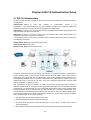
1
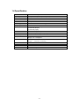
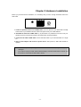
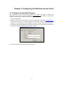
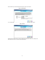
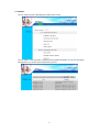
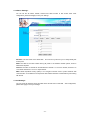
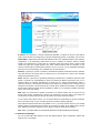
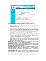
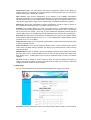
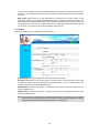
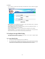
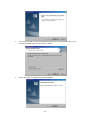
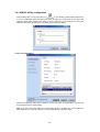
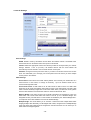
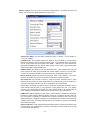
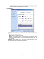
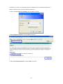
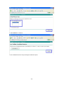
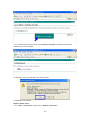
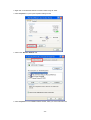
22Mbps Wireless Access Point / Bridge WAP-1965 User’s Manual Copyright Copyright 2003 by PLANET Technology Corp. All rights reserved. No part of this publication may be reproduced, transmitted, transcribed, stored in a retrieval system, or translated into any language or computer language, in any form or by any means, electronic, mechanical, magnetic, optical, chemical, manual or otherwise, without the prior written permission of PLANET. PLANET makes no representations or warranties, either expressed or implied, with respect to the contents hereof and specifically disclaims any warranties, merchantability or fitness for any particular purpose. Any software described in this manual is sold or licensed "as is". Should the programs prove defective following their purchase, the buyer (and not this company, its distributor, or its dealer) assumes the entire cost of all necessary servicing, repair, and any incidental or consequential damages resulting from any defect in the software. Further, this company reserves the right to revise this publication and to make changes from time to time in the contents hereof without obligation to notify any person of such revision or changes.. All brand and product names mentioned in this manual are trademarks and/or registered trademarks of their respective holders. Federal Communication Commission Interference Statement This equipment has been tested and found to comply with the limits for a Class B digital device, pursuant to Part 15 of FCC Rules. These limits are designed to provide reasonable protection against harmful interference in a residential installation. This equipment generates, uses, and can radiate radio frequency energy and, if not installed and used in accordance with the instructions, may cause harmful interference to radio communications. However, there is no guarantee that interference will not occur in a particular installation. If this equipment does cause harmful interference to radio or television reception, which can be determined by turning the equipment off and on, the user is encouraged to try to correct the interference by one or more of the following measures: 1. Reorient or relocate the receiving antenna. 2. Increase the separation between the equipment and receiver. 3. Connect the equipment into an outlet on a circuit different from that to which the receiver is connected. 4. Consult the dealer or an experienced radio technician for help. FCC Caution: To assure continued compliance.(example-use only shielded interface cables when connecting to computer or peripheral devices). Any changes or modifications not expressly approved by the party responsible for compliance could void the user’s authority to operate the equipment. This device complies with Part 15 of the FCC Rules. Operation is subject to the Following two conditions: (1) This device may not cause harmful interference, and (2) this Device must accept any interference received, including interference that may cause undesired operation. Federal Communication Statement Commission (FCC) Radiation Exposure This equipment complies with FCC radiation exposure set forth for an uncontrolled environment. In order to avoid the possibility of exceeding the FCC radio frequency exposure limits, human proximity to the antenna shall not be less than 20 cm(8 inches) during normal operation. R&TTE Compliance Statement This equipment complies with all the requirements of DIRECTIVE 1999/5/CE OF THE EUROPEAN PARLIAMENT AND THE COUNCIL OF 9 March 1999 on radio equipment and telecommunication terminal Equipment and the mutual recognition of their conformity (R&TTE) The R&TTE Directive repeals and replaces in the directive 98/13/EEC (Telecommunications Terminal Equipment and Satellite Earth Station Equipment) As of April 8,2000. Safety This equipment is designed with the utmost care for the safety of those who install and use it. However, special attention must be paid to the dangers of electric shock and static electricity when working with electrical equipment. All guidelines of this and of the computer manufacture must therefore be allowed at all times to ensure the safe use of the equipment. Revision User’s Manual for PLANET 22Mbps Wireless Access Point / Bridge Model: WAP-1965 Rev: 3.0 (May, 2003) Part No. EM-WAP1965v3 TABLE OF CONTENTS CHAPTER 1 INTRODUCTION .................................................................................................. 1 1.1 PACKAGE CONTENTS.......................................................................................................... 1 1.2 SYSTEM REQUIREMENTS .................................................................................................... 1 1.3 FEATURES ......................................................................................................................... 1 1.4 SPECIFICATION................................................................................................................... 2 CHAPTER 2 HARDWARE INSTALLATION.............................................................................. 3 CHAPTER 3 CONFIGURING THE WIRELESS ACCESS POINT ............................................ 4 3.1 CONFIGURE THROUGH WEB BROWSER ............................................................................... 4 3.1.1 Wizard ...................................................................................................................... 5 3.1.2 Status:....................................................................................................................... 7 3.1.3 Basic Settings:.......................................................................................................... 8 3.1.4 IP Settings: ............................................................................................................... 8 3.1.5 Advanced Settings:................................................................................................... 9 3.1.6 Security:.................................................................................................................. 11 3.1.7 802.1x..................................................................................................................... 12 3.1.8 Tools: ...................................................................................................................... 13 3.2 CONFIGURE THROUGH 22M AP UTILITY ............................................................................ 13 3.2.1 Install 22M AP Utility............................................................................................... 13 3.2.2 22M AP Utility configuration ................................................................................... 15 CHAPTER 4 802.1X AUTHENTICATION SETUP................................................................... 21 4.1 802.1X INFRASTRUCTURE ................................................................................................ 21 4.2 RADIUS SERVER SETUP ................................................................................................. 22 4.2.1 Required Services .................................................................................................. 22 4.2.2 Setup Procedure .................................................................................................... 22 4.3 AUTHENTICATOR SETUP ................................................................................................... 36 4.4 W IRELESS CLIENT SETUP ................................................................................................. 37 4.4.1 EAP-MD5 Authentication........................................................................................ 37 4.4.2 EAP-TLS Authentication......................................................................................... 40 CHAPTER 5 APPLICATION.................................................................................................... 48 5.1 ACCESS POINT MODE ....................................................................................................... 48 5.2 W IRELESS AP CLIENT MODE............................................................................................. 48 5.3 W IRELESS BRIDGE MODE ................................................................................................. 49 5.4 MULTIPLE BRIDGE MODE................................................................................................... 49 CHAPTER 6 TROUBLESHOOTING ....................................................................................... 50 Chapter 1 Introduction Thank you for purchasing WAP-1965. This device features the latest innovation wireless technology making the wireless networking world happened. This manual guides you on how to install and properly use the WAP-1965 in order to take full advantage of its features. 1.1 Package Contents Make sure that you have the following items: • • • • One WAP-1965 One AC Power Adapter One User’s Manual and Utility CD One Quick Installation Guide Note: If any of the above items are missing, contact your supplier as soon as possible. 1.2 System Requirements Before installation, please check the following requirements with your equipment. • • • Pentium Based (And Above) IBM-Compatible PC System CD-ROM drive Windows 98/ME/2000/XP Operating System with TCP/IP protocol 1.3 Features • Four operation modes selectable: AP / AP Client / Point to Point / Point to Multipoint • Utilize Direct Sequence Spread Spectrum (DSSS) technology and support the modulation of Packet Binary Convolutional Code (PBCC) mode to provide robust, interference-resistant solution in a multi-user environment • Wireless LAN IEEE802.11b compliant • Auto Fall-Back Data Rate for Long-Distance Communication and Noisy Environments • High-speed data transfer rate up to 22 Mbps • 4X mode can raise wireless performance to 44Mbps equivalent • Features Roaming, Best Access Point Selection, Load Balancing, and Network Traffic Filtering • Support 802.1X authentication • 64bit, 128bit and 256bit WEP (Wired Equivalent Privacy) • Support 63 clients to connect the network. (For best performance, the suggested maximum clients number of one WAP-1965 in AP mode is 25.) • Provide Windows-base configuration utility and Web Configuration • Support DHCP Server and Client • Support MAC Filter -1- 1.4 Specification Standard IEEE 802.11b Compliant Signal Type DSSS (Direct Sequence Spread Spectrum) Modulation QPSK / BPSK / CCK / PBCC Port One 10/100BASE-TX Antenna Dual Dipole Antenna Data Encryption 64 bit / 128 bit / 256bit WEP encryption Frequency 2.4GHz - 2.4835GHz Channel 11 Channels (US, Canada) 13 Channels (Europe) 14 Channels (Japan) Data Rate 1/2/5.5/11/22Mbps, 22Mbps+4X LED Indicators Power, TX/RX (wireless), Link (wired) Power Requirement 5V DC, 2A Temperature Operating :0 ~ 55 degree C Storage: -20 ~ 70 degree C Humidity Operating: 0 ~ 70% Storage: 0 ~ 90% Non-Condensing Dimensions 140 x 90 x 40mm Output Power 17dBm±1dBm Antenna Gain 2dBi Antenna Connector Reversed Polarity SMA Male -2- Chapter 2 Hardware Installation Before you proceed with the installation, it is necessary that you have enough information about the WAP-1965. RESET POWER ETHERNET 1. Locate an optimum location for the WAP-1965. The best place for your WAP-1965 is usually at the center of your wireless network, with line of sight to all of your mobile stations. 2. Assemble the antennas to WAP-1965. Try to place them to a position that can best cover your wireless network. The antenna’s position will enhance the receiving sensitivity. 3. Connect RJ-45 cable to WAP-1965. Connect this WAP-1965 to your LAN switch/hub or a single PC. 4. Plug in power adapter and connect to power source. After power on, WAP-1965 will start to operate. Note: ONLY use the power adapter supplied with the WAP-1965. Otherwise, the product may be damaged. If you want to reset your WAP-1965 to default settings, press the Reset button 5 second. And then wait for 10 seconds for WAP-1965 to reboot. -3- Chapter 3 Configuring the Wireless Access Point 3.1 Configure through Web Browser Web configuration provides a user-friendly graphical user interface (web pages) to manage your WAP-1965. An AP with an assigned IP address (e.g. http://192.168.1.1) will allow you to monitor and configure via web browser (e.g., MS Internet Explorer or Netscape). 1. Open your web browser. 2. Enter the IP address of your WAP-1965 in the address field (default IP address is http://192.168.1.1). Please note that your PC’s IP address should be on the same IP subnet of the WAP-1965. For example, you can configure your PC’s IP address to 192.168.1.2 if WAP-1965 is with IP 192.168.1.1. 3. A User Name and Password dialog box will appear. Please enter your User Name and Password here. Default User Name and Password are both “admin”. Click Ok. 4. Then you will see the WAP-1965 web configuration page. -4- 3.1.1 Wizard Setup wizard provides a simple way to configure your WAP-1965. Clicking “Wizard” button on top panel of WRT-1965’s web page, Setup Wizard will pop up as below.. To quick configure WAP-1965, please follow the steps below to complete the configuration. Click “Next>” to continue. Step 1. Set your new password The default password for administrator (login name is “admin”) is “admin”. You can change the Password in this step. Click “Next>”. Step 2. Set the SSID and Channel -5- Enter the SSID of your WLAN and select the frequency channel. Click “Next>”. Step 3. Set Encryption You can enable WEP encryption and set WEP key in this screen. Click “Next>” to continue. Step 4. Restart Please click the “Restart” button to save the settings and restart WAP-1965. In the following web page, please click “Close” to close the Setup Wizard window. -6- 3.1.2 Status: You can check your WAP-1965 settings and status in this screen. You can click the “View Log” button, and then the screen below will appear. You can view the logged message here. You can also clear or refresh the log record. -7- 3.1.3 Basic Settings: You can set the AP Name, ESSID, Channel and WEP function to this Access Point. After configuration, please click Apply to save your settings. AP Name: The host name of the WAP-1965. access point. This can be any name for you to easily identify this SSID: The SSID is the name shared among all points in the wireless network system, must be identical for all points. Channel: The value of channel can be selected from channel 1 to 11 for FCC domain, channels 1 to 13 for ETSI domain and 1 to 14 for Japan domain. WEP: Wired Equivalent Privacy (WEP) is an encryption scheme used to protect wireless data communication. To enable the icon will prevent other stations without the same WEP key from linking with the AP. 3.1.4 IP Settings: You can set the IP, Gateway, DHCP and DNS to this Access Point on this field. please click Apply to save your settings. -8- After configuration, IP address: This address is a unique numbers that identifies a computer or device on the WAN or LAN. These numbers are usually shown in groups separated by periods, for example: 123.123.23.2. Subnet Mask: Subnets allow network traffic between hosts to be separated based on the network's configuration. In IP networking, traffic takes the form of packets. IP subnets advance network security and performance to some level by organizing hosts into logical groups. subnet masks contain four bytes and usually appear in the same "dotted decimal" data. For example, a very common subnet mask in its binary demonstration 11111111 11111111 11111111 00000000 will usually be shown in the corresponding, more readable form as 255.255.255.0. Gateway: A gateway is a piece of software or hardware that passes information between networks. You'll see this term most often when you either log in to an Internet site or when you're transient email between different servers. DHCP: DHCP is a protocol for dynamically assigning IP addresses to networked computers. With DHCP, a computer can automatically be given an exclusive IP address each time it logs on to a network--making IP address management an easier job for network administrators. When a computer connects to the network, the DHCP server selects an IP address from a master list and assigns it to the system. The device must set to "Obtain the IP address automatically". The Wireless Access Point Gateway's DHCP server is enabled by default. If you would like to disable the DHCP server, click on the "Off" bottom. DNS: When you send email or position a browser to an Internet domain such as xxxxx.com, the domain name system translates the names into IP addresses. The term refers to two things: the conventions for naming hosts and the way the names are control across the Internet. If your network has a DHCP server, you can select Obtain IP Automatically to get the IP address from your DHCP server. Or you can select Fixed IP to set the IP settings manually. WAP-1965 has build-in DHCP server. By default is “On”. If you have a DHCP server in your network already, please set the DHCP server function to Off. When you assign an IP address to this access point, please ensure this IP address is on the same IP range as DHCP Server settings. Note: When you select Obtain IP Automatically, DHCP Sever will be disabled automatically. 3.1.5 Advanced Settings: You can set the WAP-1965 operation mode and relative settings. After configuration, please click Apply to save your settings. -9- AP Mode: WAP-1965 has four operation modes. By default, it is set to AP mode. Access Point: This mode is set to WAP-1965 by default. This connects your wireless PCs to a wired network. In most cases, no change is necessary. Up to 63 wireless clients can be connected through WAP-1965. Access Point Client: A WAP-1965 set to AP Client mode is able to talk to one WAP-1965 functioning in AP mode and wireless client within its range. This mode allows your WAP-1965 client to be the wirelessly bridged to the main WAP-1965. When you select this mode, please enter the MAC address of the main WAP-1965 into “Remote AP BSS ID” field. Or you can click on “Site Survey” button to search available AP in range. When you connect to a specific AP, its MAC address will appear on the “Remote AP BSS ID” field automatically. Wireless Bridge: This mode connects two physically separated LAN segments by using two WAP-1965s. The remote WAP-1965 also needs to be set up as a Wireless Bridge. The designated access point with which it communicates is identified by the “Remote Bridge MAC”. It corresponds to the MAC Address of the remote Wireless Bridge. Multiple Bridge: This mode allows you to construct a network that has multiple WAP-1965s bridging multiple LANs wirelessly. For all bridged WAP-1965s, configure them in Multiple Bridge mode and all the WAP-1965s must be configured on the same channel. You can have up to 14 WAP-1965 to be bridged together. Beacon Interval: Specify the Beacon Interval value. Enter a value between 1 and 1000. Beacons are packets sent by an Access Point to synchronize a wireless network. RTS Threshold: Use this field to specify a value for the RTS Threshold. Enter a value between 256 and 2432. This value should remain at its default setting of 2,432. Should you encounter inconsistent data flow, only minor modifications are recommended. Fragmentation Threshold: This field is used to specify the fragmentation threshold. Enter a value between 256 and 2346. If you experience a high packet error rate, try to slightly increase your Fragmentation Threshold. The value should remain at its default setting of 2,346. Setting the Fragmentation Threshold too low may result in poor performance. DTIM Interval (Beacon Rate): Specify the Beacon Rate. Enter a value between 1 and 65535 that specifies the Delivery Traffic Indication Message (DTIM). A DTIM is a countdown informing clients of the next window for listening to broadcast and multicast messages. When the AP has buffered broadcast or multicast messages for associated clients, it sends the next DTIM with a DTIM Interval value. AP Clients hear the beacons and awaken to receive the broadcast and multicast messages. - 10 - Authentication Type: The authentication type defines configuration options for the sharing of wireless networks to verify identity and access privileges of roaming network cards. You may choose between Open System, Shared Key, and Both. Open System: Open System authentication is the simplest of the available authentication algorithms. Essentially it is a null authentication algorithm. Any station that requests authentication with this algorithm may become authenticated if Authentication Type at the recipient station is set to Open System authentication. Open System authentication is the default authentication algorithm. Shared Key: Shared Key authentication supports authentication of STAs as either a member of those who know a shared secret key or a member of those who do not. Preamble: The preamble defines the length of the CRC block for communication between the Access Point and roaming Network Card. Long preamble ensure the network card to communicate with access point more reliably. Verify that you have selected the appropriate preamble type and click the Apply button to set it. Note: High network traffic areas should use the short preamble type. Basic Rate: The basic transfer rates should be set depending on the speed of your wireless network. Slower wireless networks should be set at 1-2 or 1-2-5.5-11(Mbps) while a faster wireless network should be set at 1-2-5.11-22 (Mbps). Supported Rate: Select one of the wireless communications transfer rates, based upon the speed of wireless adapters in WLAN. Antenna Selection: These settings determine whether either or both antennas will be used to receive data. The default setting is Diversity. This setting is uses both antennae to help overcome multi-path distortion. SSID Broadcast: Enable or disable a Service Set Identifier broadcast. When enabled, the SSID of the WAP-1965 is sent to wireless enabled devices on the area. Set the WAP-1965’s SSID in the Basic Setting screen. Enabling this function may cause unauthorized user to connect your wireless networks. 4X mode: Enable or disable 4X mode. Enable 4X mode will raise the wireless performance to 44Mbps equivalent. But, please be noted, both wireless AP and client must be using TI chipset and configured 4X mode enabled to make it effective. 3.1.6 Security: You can change Administrator ID, Password and set the MAC Filter settings in this option. Password: Enter the new password in the "AP Password New" field and again in the next field to - 11 - confirm. Click on "Apply" to execute the password change. The Password is case-sensitive, and can be made up of any keyboard characters. The new password must be between 0 and 15 characters in length. MAC Filters: Filter function is for the administrator to authorize who can gain network access through the Access Point by using MAC address filtering. By choosing the Allow radio button, only MAC addresses in the Authorization table will be allowed to communicate with the Access Point. By choosing the Deny radio button, any MAC address in the table will be denied association with the Access Point. You can have up to 50 MAC addresses configured on it. 3.1.7 802.1x This screen enables you to configure 802.1X authentication. Enable/Disable: Enable or disable 802.1X authentication of WAP-1965. Encryption Key: Select one of the Encryption key length options. It should be set the same length as WEP key. Select one of the Encryption key lifetime options. Once the lifetime expires, the Encryption key will be renewed by RADIUS server. RADIUS Server 1: Enter the IP address, communicate port number, and shared secret key of your primary RADIUS server. RADIUS Server 2: Enter the IP address, communicate port number, and shared secret key of your secondary RADIUS server. Note: As soon as 802.1X authentication is enabled, all the wireless client stations that are connected to the AP currently will be disconnected. The wireless clients must be configured manually to authenticate themselves with the RADIUS server to be reconnected. - 12 - 3.1.8 Tools: You can backup or restore WAP-1965 settings, reset WAP-1965 to factory default and upgrade firmware in this option. Backup Settings: You can backup current settings to a file. Press “Backup” button, it will prompt you a location to save the backup file (config.bin). Restore Settings: When you try to restore the settings you have saved, please press “Browse…” to find out the backup file and then press “Restore”. Restore to default settings: It is used to reset WAP-1965’s configuration to factory default. Firmware Upgrade: You can upload the newest firmware of the WAP-1965. You may either enter the file name in the entry field or browse the file by clicking the Browse button. 3.2 Configure through 22M AP Utility The 22M AP Utility is provided to configure the WAP-1965. It can be used to configure multiple WAP-1965s at the same time in an easiest way. 3.2.1 Install 22M AP Utility 1. Insert the User’s Manual and Utility CD into the CD-ROM drive. 2. Run “setup.exe” under “E:\Utility\WAP-1965\” directory, or click the “Start” button and choose “Run”. When the dialog box appears, enter “E:\Utility\WAP-1965\setup.exe” (Assume “E” is your CD-ROM drive). You will see the dialog box as below. Please click “Next” to continue. - 13 - 3. You can click “Browse” to specify the Destination Folder that you want to install the utility. Or you can keep the default setting and click ”Next” to continue. 4. Please click “Finish” to complete the software installation. - 14 - 3.2.2 22M AP Utility configuration After installing utility, you can found the icon on your desktop, please double click this icon to run the configuration utility and select each option to setup your Access Point as you need. After settings in each option, please press “Apply” to save. It will show you the dialog box to enter User Name and Password. By default, the User Name and Password is “admin”. 3.2.2.1 Link Information When the configuration utility starts, it will show you the first option “Link Information”. You can view the first Access Point’s current setting. Note: If you have many WAP-1965, all the WAP-1965s will list in “Available AP”. You can select the WAP-1965 that you want to check, then you can see the settings of the WAP-1965. - 15 - 3.2.2.2 AP Settings Basic Settings: ESSID: ESSID is used by all wireless devices within the wireless network. The ESSID value must be the same on all stations and Access points in this WLAN. Channel: Select the appropriate channel from the list provided to correspond with your network settings, between 1 and 13 (in ETSI). All wireless devices with the same ESSID will automatically use this channel to communicate with this access point. AP Name: Change the access point name here, if you want to set another name to this Access Point. This will enable you to manage your access points with more ease if you have multiple access points in the network. Mode Settings: Access Point: This mode is set to WAP-1965 by default. This connects your wireless PCs to a wired network. In most cases, no change is necessary. Up to 63 wireless clients can be connected through WAP-1965. Access Point Client: A WAP-1965 set to AP Client mode is able to talk to one WAP-1965 functioning in AP mode and wireless client within its range. This mode allows your WAP-1965 client to be the wirelessly bridged to the main WAP-1965. When you select this mode, please enter the MAC address of the main WAP-1965 into “Remote AP BSS ID” field. Wireless Bridge: This mode connects two physically separated LAN segments by using two WAP-1965s. The remote WAP-1965 also needs to be set up as a Wireless Bridge. The designated access point with which it communicates is identified by the “Remote Bridge MAC”. It corresponds to the MAC Address of the remote Wireless Bridge Multiple Bridge: This mode allows you to construct a network that has multiple WAP-1965s bridging multiple LANs wirelessly. For all bridged WAP-1965s, configure them in Multiple Bridge mode and all the WAP-1965s must be configured on the same channel. You can have up to 14 WAP-1965 to be bridged together. - 16 - Advance setting: when you press the “Advance Setting button”, the dialog box below will appear. You can set more details parameters in this screen. Transmission Rates: You may select transmission rate to “1-2Mbps”, “1-2-5.5-11Mbps” or “1-2-5.5-11-22Mbps”. Preamble Type: The preamble defines the length of the CRC block for communication between the Access Point and roaming Network Card. Long preamble ensure the network card to communicate with access point more reliably. Verify that you have selected the appropriate preamble type and click the Apply button to set it. Note: High network traffic areas should use the short preamble type SSID Broadcast: This allows the AP to broadcast its SSID. Other wireless client with site survey function can easily know this SSID and use this SSID to connect your access point. To secure your wireless network from unauthorized users, please disable this function. Beacon Interval: Specify the Beacon Interval value. Enter a value between 1 and 1000. Beacons are packets sent by an Access Point to synchronize a wireless network. RTS Threshold: Use this field to specify a value for the RTS Threshold. Enter a value between 256 and 2432. This value should remain at its default setting of 2,432. Should you encounter inconsistent data flow, only minor modifications are recommended. Fragmentation Threshold: This field is used to specify the fragmentation threshold. Enter a value between 256 and 2346. If you experience a high packet error rate, try to slightly increase your Fragmentation Threshold. The value should remain at its default setting of 2,346. Setting the Fragmentation Threshold too low may result in poor performance. DTIM Interval: Specify the Beacon Rate. Enter a value between 1 and 65535 that specifies the Delivery Traffic Indication Message (DTIM). A DTIM is a countdown informing clients of the next window for listening to broadcast and multicast messages. When the AP has buffered broadcast or multicast messages for associated clients, it sends the next DTIM with a DTIM Interval value. AP Clients hear the beacons and awaken to receive the broadcast and multicast messages. Antenna Selection: These settings determine whether either or both antennas will be used to receive data. The default setting is Diversity. This setting is uses both antennae to help overcome multi-path distortion. - 17 - 4X mode: Enable or disable 4X mode. Enable 4X mode will raise the wireless performance to 44Mbps equivalent. But, please be noted, both wireless AP and client must be using TI chipset and configured 4X mode enabled to make it effective. 3.2.2.3 IP Settings Fix IP Address: You may give a fixed IP address to WAP-1965 manually by choosing this radio button. IP Address: Set an IP address for the AP. Subnet mask: Set the Subnet Mask for the AP. Gateway: The IP address of a gateway device necessary for communication with devices outside the subnet of the Access Point. If your network is not divided onto different subnets, this can remain blank. DHCP Client: If there is a DHCP Server in your LAN, you can select DHCP Client to let the WAP-1965 be a client to get an IP address from your DHCP server. - 18 - 3.2.2.4 WEP Settings Data Encryption: Select this option when you want to enable WEP function. Auth. Mode: Open Authentication: With this setting, any station in the WLAN can receives and transmits data from the Access Point (null authentication). Shared Authentication: With this setting, only stations using shared key encryption identified by the Access Point are allowed to associate with it. Auto Switch: With this setting, stations can communicate with the Access Point either with or without data encryption. WEP Key Settings: You can define the WEP (Wired Equivalent Privacy) function by yourself. There are 4 keys available, please ensure you have enter correct number for the key values with different Key Length and coding (Hex or ASCII) as 64bit (10 Hex digit / 5 ASCII), 128bit (26 Hex digit / 13 ASCII) or 256bit (58 Hex digit / 29 ASCII), please select one of them and enter the key you want to use. When Hex is selected, you may enter alphanumeric characters in the range of “A-F”, “a-f” and “0-9” in the WEP Key entry field. Alternatively, you may enter digit hexadecimal values in the range of “a-z”, “A-Z” and “0-9”. Note: If you have many WAP-1965s in LAN and you want to set them have the same WEP key. You can set one of them, and then select all the WAP-1965 in the “Available AP” and press Apply. You will see a dialog box appears as below. You can enter their User Name and Password in this dialog box and Click OK to apply. - 19 - 3.2.2.5 802.1x Settings 802.1X Function: Enable or disable 802.1X authentication of WAP-1965. Encryption Key: Select one of the Encryption key length options. It should be set the same length as WEP key. Select one of the Encryption key lifetime options. Once the lifetime expires, the Encryption key will be renewed by RADIUS server. RADIUS Server 1: Enter the IP address, communicate port number, and shared secret key of your primary RADIUS server. RADIUS Server 2: Enter the IP address, communicate port number, and shared secret key of your secondary RADIUS server. Note: As soon as 802.1X authentication is enabled, all the wireless client stations that are connected to the AP currently will be disconnected. The wireless clients must be configured manually to authenticate themselves with the RADIUS server to be reconnected. - 20 - Chapter 4 802.1X Authentication Setup 4.1 802.1X Infrastructure An 802.1X Infrastructure is composed of three major components: Authenticator, Authentication server, and Supplicant. Authentication server: An entity that provides an authentication service to an authenticator. This service determines, from the credentials provided by the supplicant, whether the supplicant is authorized to access the services provided by the authenticator. Authenticator: An entity at one end of a point-to-point LAN segment that facilitates authentication of the entity attached to the other end of that link. Supplicant: An entity at one end of a point-to-point LAN segment that is being authenticated by an authenticator attached to the other end of that link. In the following sections, we will guide you to build an 802.1X Infrastructure step by step. The instructions are divided into three parts: RADIUS Server Setup: Microsoft Windows 2000 server. Authenticator Setup: WAP-1965. Wireless Client Setup: Microsoft Windows XP. The above graph shows the network topology of the solution we are going to introduce. As illustrated, a group of wireless clients is trying to build a wireless network with WAP-1965 in order to have access to both Internet and Intranet. With 802.1X authentication, each of these wireless clients would have to be authenticated by RADIUS server. If the client is authorized, WAP-1965 would be notified to open up a communication port to be used for the client. There are 2 Extensive Authentication Protocol (EAP) methods supported: (1) MD5 and (2) TLS. MD5 authentication is simply a validation of existing user account and password that is stored in a database of RADIUS server. Therefore, wireless clients will be prompted for account/password validation to build the link. TLS authentication is a more complicated authentication, which is using certificate that is issued by RADIUS server for authentication. TLS authentication is a more secure authentication, since not only RADIUS server authenticates the wireless client, but also the client can validate RADIUS server by the certificate that it issues. The TLS authentication request from wireless clients and reply by Radius Server and WAP-1965 can be briefed as follows: 1. The client sends an EAP start message to WAP-1965. 2. WAP-1965 replies with an EAP Request ID message. 3. The client sends its Network Access Identifier (NAI) – its user name – to WAP-1965 in an EAP Respond message. 4. WAP-1965 forwards the NAI to the RADIUS server with a RADIUS Access Request message. - 21 - 5. The RADIUS server responds to the client with its digital certificate. 6. The client validates the digital certificate, and replies its own digital certificate to the RADIUS server. 7. The RADIUS server validates client’s digital certificate. 8. The client and RADIUS server derive encryption keys. 9. The RADIUS server sends WAP-1965 a RADIUS ACCEPT message, including the client’s WEP key. 10. WAP-1965 sends the client an EAP Success message along with the broadcast key and key length, all encrypted with the client’s WEP key. 4.2 RADIUS Server Setup 4.2.1 Required Services After Windows 2000 server has been installed, please install Service Pack 2 also and other latest security patch. Furthermore, the following service components are needed: n Active Directory (Please consult with your network administrator or an engineer who is familiar with Windows 2000 server to install Active Directory; otherwise your system or network might be unstable.) n IAS (Internet Authentication Service) n Web Server (IIS) n Certificate Service 4.2.2 Setup Procedure 1. Login into Windows 2000 Server as Administrator, or account that has Administrator authority. 2. Go to Start > Control Panel, and double-click “Add or Remove Programs”. 3. Click on “Add/Remove Windows components”. 4. Check “Certificate Services”, and click “Next” to continue. - 22 - 5. Select “Enterprise root CA”, and click “Next” to continue. 6. Enter the information that you want for your Certificate Service, and click “Next” to continue. 7. Go to Start > Program > Administrative Tools > Certificate Authority. 8. Right-click on the “Policy Setting”, select “new”. 9. Select “Certificate to Issue”. 10. Select “Authenticated Session” and “Smartcard Logon” by holding down to the Ctrl key, and click - 23 - “OK” to continue. 11. Go to Start > Program > Administrative Tools > Active Directory Users and Computers. 12. Right-click on domain, and select ”Properties” to continue. 13. Select “Group Policy” tab and click “Properties” to continue. - 24 - 14. Go to “Computer Configuration” > “Security Settings” > “Public Key Policies” 15. Right-click “Automatic Certificate Request Setting”, and select “New” 16. Click “Automatic Certificate Request ...” - 25 - 17. The Automatic Certificate Request Setup Wizard will guide you through the Automatic Certificate Request setup, simply click “Next” through to the last step. 18. Click “Finish” to complete the Automatic Certificate Request Setup 19. Go to Start > Run, and type “command” and click “Enter” to open Command Prompt. 20. Type “secedit/refreshpolicy machine_policy” to refresh policy. Adding Internet Authentication Service 21. Go to Start > Control Panel > Add or Remove Programs. 22. Select “Add/Remove Windows Components” from the panel on the left. 23. Select “Internet Authentication Service”, and click “OK” to install. - 26 - Setting Internet Authentication Service 24. Go to Start > Program > Administrative Tools > Internet Authentication Service. 25. Right-click “Client”, and select “New Client”. 26. Enter the IP address of WAP-1965 in the Client address text field, a memorable name for WAP-1965 in the Client-Vendor text field, the access password used by WAP-1965 in the Shared secret text field. Re-type the password in the Confirmed shared secret text field. - 27 - 27. Click “Finish”. 28. In the Internet Authentication Service, right-click “Remote Access Policies” 29. Select “New Remote Access Policy”. 30. Select “Day-And-Time-Restriction”, and click “Add” to continue. - 28 - 31. Unless you want to specify the active duration for 802.1X authentication, click “OK” to accept for having 802.1x authentication enabled at all times. 32. Select “Grant remote access permission”, and click “Next” to continue. - 29 - 33. Click “Edit Profile”. For TLS Authentication Setup (Steps 34 ~ 35) 34. Select “Authentication” Tab. 35. Enable “Extensible Authentication Protocol”, and select “Smart Card or other Certificate” for TLS authentication. Click “OK”. Then go to step 38. - 30 - For MD5 Authentication Setup (Steps 36 ~ 37) 36. Select “Authentication” Tab. 37. Enable “Extensible Authentication Protocol”. Select “MD5-Challenge” and enable “Encrypted Authentication (CHAP)” for MD5 authentication. Click “OK”. - 31 - 38. Select “Internet Authentication Service (Local)”, click on “Action” from top panel. Then click “Register Service in Active Directory”. 39. Go to Start > Program > Administrative Tools > Active Directory Users and Computers. 40. Right click on the domain, and select “Properties”. 41. Select “Group Policy” tab, and click “Edit” to edit the Group Policy. - 32 - 42. Go to “Computer Configuration” > “Windows Settings” > “Security Settings” > “Account Policies” > “Password Policies”. Double click on “Store password using reversible encryption for all users in the domain”. - 33 - 43. Click “Define this policy setting”, select “Enabled”, and click “OK” to continue. 44. Go to Start > Program > Administrative Tools > Active Directory Users and Computers. 45. Go to Users. Right-click on the user that you are granting access, and select “Properties”. 46. Go to “Account” tab, and enable “Store password using reversible encryption”. 47. Click “Apply” to continue. - 34 - 48. Go to the “Dial-in” tab, and check “Allow access” option for Remote Access Permission and “No Call-back” for Callback Options. Then click “OK”. - 35 - 4.3 Authenticator Setup 1. For EAP-MD5 Authentication, WEP key must be set previously. Go to Basic Settings. Enable WEP key, and enter a desired key string. You can skip this step if using EAP-TLS Authentication. 2. Click on 802.1X for detailed configuration. 3. Enable 802.1X Authentication by selecting “Enable”. 4. If EAP-MD5 is used, you can leave the settings in Encryption Key Length and Lifetime as default. If you are using EAP-TLS authentication, set the Encryption Key Length ranging from 64 to 256 Bits and the Lifetime from 5 Minutes to 1 Day. As soon as the lifetime expires, the Encryption Key will be renewed - 36 - by RADIUS server. 5. Enter the IP address, Port number, and Shared Secret Key used by the Primary Radius Server. 6. Enter the IP address, Port number, and Shared Secret Key used by the Secondary Radius Server. 7. Click “Apply”. The 802.1x settings will take effect right after WAP-1965 reboots itself. You can also use utility to configure 802.1X settings. The procedures are similar to above described. 4.4 Wireless Client Setup Windows XP is originally 802.1X support. As to other operating systems (windows 98SE, ME, 2000), an 802.1X client utility is needed. The following procedures show how to configure 802.1X Authentication with WL-3555 in Windows XP. Please note that if you want to change the 802.1x authentication type of a wireless client, i.e. switch to EAP-TLS from EAP-MD5, you must remove the current existing wireless network from your preferred connection first, and add it in again. 4.4.1 EAP-MD5 Authentication 1. Go to Start > Control Panel, double-click on “Network Connections”. 2. Right-click on the Wireless Network Connection which using WL-3555. 3. Click “Properties” to open up the Properties setting window. 4. Click on the “Wireless Network” tab. - 37 - 5. Click “Properties” of one available wireless network, which you want to associate with. 6. Select “Data encryption (WEP enabled)” option, but leave other options unselected. - 38 - 7. Enter the network key in “Network key” text box. The string must be the same as the first set of WEP key which you set to WAP-1965. 8. Click “OK”. 9. Select “Authentication” tab. 10. Select “Enable network access control using IEEE 802.1X” to enable 802.1x authentication. 11. Select “MD-5 Challenge” from the drop-down list box for EAP type. 12. Click “OK”. - 39 - 13. When wireless client has associated with WAP-19655, a user authentication notice appears in system tray. Click on the notice to continue. 14. Enter the user name, password and the logon domain that your account belongs. 15. Click “OK” to complete the validation process. 4.4.2 EAP-TLS Authentication Get Digital Certificate from Server The following procedures are based on obtaining a certificate from Windows 2000 Server which acts as a CA server. Furthermore, you must have a valid account/password to access the server. 1. Active web browser, enter “http://192.168.1.10/certsrv” in the Address field which 192.168.1.10 is the - 40 - IP address of our server. This will directly access to Certificate Service of a Windows 2000 server. A dialog box will prompt you to enter user name and password. 2. Enter a valid user name and password, then click “OK” to continue. 3. Select “Request a certificate”, and click “Next” to continue. 4. Select “User Certificate request”, and click “Next” to continue. - 41 - 5. Click “Submit >” to continue. 6. The Certificate Service is now processing the certificate request. - 42 - 7. The certificate is issued by the server, click “Install this certificate” to download and store the certificate to your local computer. 8. Click “Yes” to store the certificate to your local computer. 9. Certificate is now installed. Wireless Adapter Setup 1. Go to Start > Control Panel, double-click on “Network Connections”. - 43 - 2. Right-click on the Wireless Network Connection which using WL-3555. 3. Click “Properties” to open up the Properties setting window. 4. Click on the “Wireless Network” tab. 5. Click “Properties” of one available wireless network, which you want to associate with. - 44 - 6. Select “The key is provided for me automatically” option. 7. Click “OK”. 8. Click “Authentication” tab 9. Select “Enable network access control using IEEE 802.1X” option to enable 802.1x authentication. - 45 - 10. Select “Smart Card or other Certificate” from the drop-down list box for EAP type. 11. Click “OK”. 12. When wireless client has associated with WAP-1965, Windows XP will prompt you to select a certificate for wireless network connection. If you only have one certificate in local computer, system will automatically use it for authenticate. If you have multiple certificates in local computer, click on the network connection icon in the system tray to continue. 13. Select the certificate that was issued by the server (in our demonstration: WirelessCA), and click “OK” to continue. - 46 - 14. Make sure this certificate is issued by correct server, and click “OK” to complete the authentication process. - 47 - Chapter 5 Application This chapter describe the four operating mode of your WAP-1965. The four working modes of WAP-1965 are Access Point, Access Point Client Mode, Wireless Bridge mode and Multiple Bridge mode. 5.1 Access Point mode With this mode, your Wireless network connection could act as following. Any of your IEEE802.11b end nodes should found the nearest Access Point to communication with any other Wireless end-nodes or the wired Ethernet network. There are two things need to be check for your wireless end nodes, the services set ID (SSID) and the Wired Equivalent Protocol (WEP), both parameters should the same with your Access Point. 5.2 Wireless AP Client mode The WAP-1965 can also act as a client on a wireless LAN. When configured as AP Client mode, WAP-1965 soon makes your connected PC a wireless end node. This mode can be deployed if your end nodes (already installed with an Ethernet Adapter) do not want to make any change but want to move it somewhere not easy to have the wire. In this mode, WAP-1965 will need to accompany with an existing WAP-1965 in access point mode in the wireless network. - 48 - 5.3 Wireless Bridge mode The Wireless Bridge mode help to make the two Ethernet networks connected without any wire. With two WAP-1965s in this mode, the two LANs in distance can communicate to each other. This could be deployed if the networks are hard to make the wire in between. Please be noted, please key in the MAC address to make the WAP-1965 communicate with a specific remote Access Point, you can find the MAC address either from the utility or from the label under the Access Point. The omni antenna is with 17dBm transmitting power, if you would like to make longer distance that the default antenna cannot reach, consult your local dealer for more about how to extend your distance. Note: Please do consult your local dealer about the external or directional antenna you would like to install and get the connection. Improper outdoor antenna installation could damage the Access Point or get injured or get killed in some condition like thunders or strong winds. 5.4 Multiple Bridge mode For multiple LANs, the WAP-1965 also helps to make the connections. With this mode, three or more LANs can bridge to each other. Note: The mode “Multiple Bridge” will turns the Access Points, for example the above three Access point in the figure, into one network domain. This also means your three Ethernet networks will use 22Mbps transmission rate to communicate with each other. In a large network, please consider using management device to reduce the network broadcast to the wireless network. - 49 - Chapter 6 Troubleshooting This chapter gives tips on how to configure the communication software. This chapter provides solutions to problems usually encountered during the installation and operation of the Wireless Network Access Point. Read the description below to solve your problems. Can I run an application from a remote computer over the wireless network? This will depend on whether or not the application is designed to be used over a network. Consult the application’s user guide to determine if it supports operation over a network. Can, I play games with other members of the cordless network? Yes, as long as the game supports multiple plays over a LAN (local area network). Refer to the game’s user guide for more information. What is the IEEE 802.11b standard? The IEEE 802.11b Wireless LAN standards subcommittee, which is formulating a standard for the industry. The objective is to enable wireless LAN hardware from different manufactures to communicate. What IEEE 802.11 features are supported? The product supports the following IEEE 802.11 functions: w CSMA/CA plus Acknowledge protocol w Multi-Channel Roaming w Automatic Rate Selection w RTS/CTS feature w Fragmentation w Power Management What is PBCC? This new products use the ACX100 chip from Texas Instruments. In addition to meeting the existing standard, the chip also supports a new modulation scheme developed by TI, called Packet Binary Convolution Code (PBCC). It's this scheme that gives the products the extra kick: Even at lower speeds, PBCC provides better performance at greater distances, and it can also work at 22 Mbps. What is Ad-hoc? An Ad-hoc integrated wireless LAN is a group of computers, each with a WLAN adapter, Connected as an independent wireless LAN. Ad hoc wireless LAN is applicable at a departmental scale for a branch or SOHO operation. What is Infrastructure? An integrated wireless and wired LAN is called an Infrastructure configuration. Infrastructure is applicable to enterprise scale for wireless access to central database, or wireless application for mobile workers. What is Roaming? Roaming is the ability of a portable computer user to communicate continuously while moving freely throughout an area greater than that covered by a single Wireless Network Access Point. Before using the roaming function, the workstation must make sure that it is the same channel number with the Wireless Network Access Point of dedicated coverage area. - 51 -