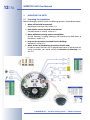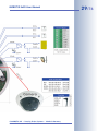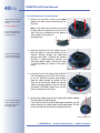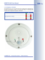
1
EN
ExtIO User Manual
The HiRes Video Company
HiRes
6 Megapixel
EN
4096 x 1536
Software zoom
Skyline
Format free
Each image format
freely definable
30 Frames/s
VGA (640 x 480)
30 F/s Mega
Virtual PTZ
Digital pan, tilt,
zoom
Backlight
ExtIO Opens New Horizons for Cameras
Safe using CMOS
without mechanical iris
Internal DVR
Internal via Flash,
external via Network
Win/Lin/Mac
Recording
via Network on PC
up to 1 Terabyte
Microphone & speaker
Audio
bi-directional via IP,
variable framerates
SIP-Client with video
IP Telephony
Alarm notify,
cam remote control
VideoMotion
60.154_EN_V2_11/2012
Multiple windows
precision pixel-based
-22 to +140 °F
Weatherproof
-30 to +60 °C, IP65,
no heating necessary
Latest PDF file:
www.mobotix.com > Support > Manuals
IEEE 802.3af
PoE
www.mobotix.com
Network power
even in winter
HiRes Video Innovations
The German company MOBOTIX AG is known as the leading pioneer in network camera technology and its
decentralized concept has made high-resolution video systems cost efficient.
MOBOTIX AG • D-67722 Langmeil • Tel: +49-6302-9816-103 • Fax: +49-6302-9816-190 • [email protected]
Robust
No moving parts
fiber glass housing
MxCC/MxEasy
Licence free
Video-ManagementSoftware
MOBOTIX ExtIO User Manual
Notes
Note:
MOBOTIX offers inexpensive seminars that include a workshop and
practical exercises: Basic Seminar three days, Advanced Seminar two
days.
For more information, please visit www.mobotix.com.
© MOBOTIX AG • Security-Vision-Systems • Made in Germany
www.mobotix.com • [email protected]
1/76
MOBOTIX ExtIO User Manual
EXTIO USER MANUAL
1
INTRODUCTION
4
1.1
MOBOTIX ExtIO Concept
6
1.2 The MOBOTIX ExtIO and MOBOTIX Cameras
1.2.1 Functional Overview of the ExtIO
1.2.2 Comparison ExtIO/CamIO
8
8
9
1.3
Accessories
10
2
MOUNTING THE EXTIO
12
2.1
2.1.1
2.1.2
2.1.3
2.1.4
2.1.5
Preparing the Installation
Mounting to a Wall or Ceiling
Connecting via Network or USB
Mounting Options
Providing the Camera Connections, Wall Outlets
Directions for Mounting
12
13
13
14
14
15
2.2
2.2.1
2.2.2
2.2.3
2.2.4
ExtIO: Delivered Parts, Components and Dimensions
Delivered Parts and Components
Housing
ExtIO Dimensions
Drilling Template Mounting Ring
16
16
17
18
18
2.3
2.3.1
2.3.2
2.3.3
2.3.4
ExtIO Accessories: Delivered Parts, Components and Dimensions
On-Wall Set
In-Ceiling Set
Wall Mount
Pole Mount
20
20
22
24
26
2.4
2.4.1
2.4.2
2.4.3
2.4.4
Connecting the Terminal Connectors, Wiring
Overview: ExtIO Board and Connectors
ExtIO Terminal Connector for the Ethernet Cabling
ExtIO Terminal Connector 1 (Signal Inputs/Outputs)
ExtIO Terminal Connector 2 (Line-In/Line-Out)
30
30
31
32
33
2.5
2.5.1
2.5.2
2.5.3
2.5.4
2.5.5
Connecting a MOBOTIX USB Cable to the Camera
Overview
Establishing the USB Connection to a D22M Camera
Establishing the USB Connection to a M22M Camera
Establishing the USB Connection to a M12 Camera
Establishing the USB Connection to a D12 Camera
34
34
35
36
38
40
2.6
2.6.1
2.6.2
2.6.3
Connecting the Cable to the ExtIO
Connecting the Ethernet Cable to the ExtIO
Connecting the USB Cable to the ExtIO
Connecting Additional Cables to the ExtIO
42
42
44
46
2.7 Mounting the ExtIO
2.7.1 Mounting the ExtIO Without Additional Mounting Options
© MOBOTIX AG • Security-Vision-Systems • Made in Germany
www.mobotix.com • [email protected]
48
48
2/76
MOBOTIX ExtIO User Manual
2.8
2.8.1
2.8.2
2.8.3
2.8.4
2.8.5
2.8.6
Important Notes
Safety Regulations
Suitable Cables for the MOBOTIX ExtIO
Safety Notes for Operating the MOBOTIX ExtIO
Weatherproofness, Temperature Range
Cleaning Instructions
Additional Information
50
50
50
51
52
52
52
3
OPERATION OF THE EXTIO
54
3.1
3.1.1
3.1.2
3.1.3
3.1.4
3.1.5
3.1.6
Activating the ExtIO
Activating the USB Operating Mode
Activating the Ethernet Mode (NET)
Setting up the Network Parameters of the ExtIO for Ethernet Operation
LED-Patterns of the ExtIO
Starting the ExtIO Using the Factory Default Settings
Starting the ExtIO With an Automatic IP Address (DHCP)
54
55
56
57
59
60
61
3.2
3.2.1
3.2.2
3.2.3
3.2.4
3.2.5
3.2.6
Sensors and Input/Output Interfaces of the ExtIO
Status LEDs
Speaker and Microfon
Buttons
PIR Motion Sensor
Signal Inputs/Outputs
Temperature Sensor
62
62
62
63
63
63
64
3.3
Software Updates
65
3.4
3.4.1
3.4.2
3.4.3
3.4.4
Configuration Sample
Functional Overview
Overview of the Configuration Steps
Configuring the MOBOTIX Camera
Configuring a Softphone
66
66
67
67
73
APPENDIX: DECLARATION OF CONFORMITY
DRILLING TEMPLATES (SCALE 1:1)
Information subject to change without notice!
Copyright © 1999-2008 MOBOTIX AG, Kaiserslautern, Germany.
All rights reserved. MOBOTIX, MxPEG and MxControlCenter are worldwide
trademarks of MOBOTIX AG. Microsoft, Windows and Windows Server are registered trademarks of Microsoft Corporation. Apple, the Apple logo, Macintosh,
OS X and Bonjour are trademarks of Apple Inc. Linux is a trademark of Linus
Torvalds. All other marks and names mentioned herein may be trademarks or
registered trademarks of the respective owners.
© MOBOTIX AG • Security-Vision-Systems • Made in Germany
www.mobotix.com • [email protected]
MOBOTIX ExtIO User Manual
Notes
© MOBOTIX AG • Security-Vision-Systems • Made in Germany
www.mobotix.com • [email protected]
3/76
4/76
MOBOTIX ExtIO User Manual
1
*You can use the ExtIO
with all MOBOTIX IT
and Secure models.
MOBOTIX Q22M models
can only be connected to
the ExtIO using Ethernet.
INTRODUCTION
The MOBOTIX ExtIO is the weatherproof, compact expansion
and connection box for connecting all MOBOTIX cameras (IT
and Secure models). This box expands the cameras by a powerful audio unit with microphone and speaker, a passive-Infrared detector, an external temperature sensor, an illumination sensor as well as two signal inputs and two signal outputs. The two large buttons on the unit allow easily implementing door and gate communication solutions.
In the security and house technology area, the MOBOTIX ExtIO represents the ideal
addition to the MOBOTIX cameras, especially if you would like to control e.g.
lamps, doors, controls wires or other external devices using pushbuttons. The
signal output can also be used to connect the MOBOTIX camera via the ExtIO to the
input of an alarm system, for example.
You can also attach external sensors to the MOBOTIX camera via the ExtIO, e.g. to
evaluate remote sensors, such as light barriers, reed switches, external PIR sensors
or the output of an alarm system.
You can easily mount the MOBOTIX ExtIO remotely (i.e. not directly near) a
MOBOTIX camera inside of a building or outside, to a wall or ceiling. Its weatherproof housing (IP65) reliably protects the ExtIO against any kind of weather. The
connection to the MOBOTIX camera can be established using either the LAN (Ethernet cabling) or a special MOBOTIX USB cable (specific for each camera model;
max. 5 m/16 ft long). In both cases, the camera's power supply uses the cable
(LAN/PoE or USB). As power is supplied via the cabling, the ExtIO does not require
its own power supply.
Ethernet & USB
© MOBOTIX AG • Security-Vision-Systems • Made in Germany
www.mobotix.com • [email protected]
MOBOTIX ExtIO User Manual
© MOBOTIX AG • Security-Vision-Systems • Made in Germany
www.mobotix.com • [email protected]
5/76
6/76
MOBOTIX ExtIO User Manual
1.1
MOBOTIX ExtIO Concept
Simple Installation
When designing the MOBOTIX ExtIO, special focus was placed on easy installation
of the expansion box. The supplied drilling template facilitates mounting the ExtIO
and makes connecting the cabling for data and audio connections easy, secure
and weatherproof.
Buttons
The two buttons of the ExtIO can be used to control its two signal outputs, for example. In addition, a MOBOTIX camera connected to the ExtIO can react to the
pressed button and can execute the messaging options and actions defined in the
MOBOTIX camera.
Switching external Devices
Using the two galvanically separated signal outputs, the ExtIO can switch devices
with up to 50 V AC or DC and max. 100 mA (5 W).
Speaker
Temperature sensor
L button (lights)
R button (door bell)
Microphone
PIR motion detector
Illumination sensor
© MOBOTIX AG • Security-Vision-Systems • Made in Germany
www.mobotix.com • [email protected]
7/76
MOBOTIX ExtIO User Manual
Using External Sensors
Using the two galvanically separated signal inputs of the ExtIO, the MOBOTIX camera can monitor external sensors and apply the different mechanisms available to
the camera for storing audio/video and for sending notification messages.
Weatherproofness
The weatherproofness of the MOBOTIX ExtIO has been tested extensively; the ExtIO
reaches protection class IP65 (absolutely dustproof and resistant against water
jets).
Robust and durable
Like all other MOBOTIX products, the ExtIO has been designed for a long product
life. The housing from PBT-GF30 is robust and reliably protects the interior of the
ExtIO.
Terminal connectors
for Ethernet cabling
Terminal connector for signal inputs and outputs
Terminal connector for Line-In
and Line-Out
© MOBOTIX AG • Security-Vision-Systems • Made in Germany
www.mobotix.com • [email protected]
Mini USB
connector
8/76
MOBOTIX ExtIO User Manual
1.2 The MOBOTIX ExtIO and MOBOTIX Cameras
ExtIO
MX-EXTIO
1.2.1 Functional Overview of the ExtIO
*IEEE 802.3af required
You can use the ExtIO
with all MOBOTIX IT
and Secure models.
MOBOTIX Q22M models
can only be connected to
the ExtIO using Ethernet.
Note that the cable required for connecting the
ExtIO (MOBOTIX USB
cable or Ethernet installation cable) is not included in the delivered
parts.
If you would like to use
a USB cable to connect
the ExtIO to a camera,
please order the corresponding MOBOTIX USB
cable for your camera
model:
M12/D12:
SUB HD to Mini USB
MX-CBL-HD-MU-5
(5 m/16 ft)
M22M:
USB to Mini USB
MX-CBL-U-MU-5
(5 m/16 ft)
D22M:
Mini-USB to Mini-USB
MX-CBL-MU-MU-1
(1 m/3 ft)
MX-CBL-MU-MU-5
(5 m/16 ft)
Hardware Features
Outdoor - weatherproof
IP65
Using PoE (Class 2)* or USB cable
Power Supply
Speaker, microphone, 2 status LEDs,
PIR motion detector, 2 buttons, external temperature sensor,
illumination sensor
Sensors
Concealed cabling
Yes
Dimensions/Weight
160 x 42 mm/6.3 x 1.7 in (dia. x height), approx. 430 g/15.2 ounces
Audio
Speaker
0.5 W / 8 Ohm
Microphone
X
Line-Out / Line-In
X/X
Outputs
Count
2 (galvanically separated)
Max. switching voltage
50 V~ / 50 V=
Min. switching voltage
5 V~ / 5 V=
Max. amperage
100 mA
Min. amperage
-
Max. inductive load
6 VA
Max. Ohm resistive load
5W
Open Collector
-
Galvanically separated
X
Inputs
Count
2 (galvanically separated)
Max. voltage
50 V~ / 50 V=
Min. voltage
self-powered
Min. amperage
-
Switching level
High active
© MOBOTIX AG • Security-Vision-Systems • Made in Germany
www.mobotix.com • [email protected]
9/76
MOBOTIX ExtIO User Manual
1.2.2 Comparison ExtIO/CamIO
Hinweis
Supported MOBOTIX models
Outdoor - weatherproof
Power Supply
Power input
Integrated recharg. battery
CamIO
Hardware Features
ExtIO
Zur Nutzung aller Funktionen der ExtIO ist die Aktivierung über die
ExtIO
CamIO
all models*
M12, M22**
IP65
IP65
PoE (Class 2)*** / USB
230 V AC / PoE
typ. 1 W
typ. 3.5 W
-
(only ACplus model for M12)
Speaker, microphone
Sensors
Concealed cabling
2 status LEDs, 2 buttons
PIR motion detector,
temperature, illumination
Speaker****
Yes
Yes
160 x 42 mm/6.3 x 1.7 in
(dia. x height)
136 x 163 x 158 mm/5.4 x 6.4 x
6.2 in (width x depth x height)
0.5 W
2.5 W****
X
-
X/X
X/X
2 (galvanically separated)
2 (galvanically separated)
Max. switching voltage
50 V~ / 50 V=
230 V~ / 48 V~/68 V=
Min. switching voltage
5 V~ / 5 V=
5 V~ / 5 V=
Max. amperage
100 mA
5A
Min. amperage
-
100 mA
Max. inductive load
6 VA
600 VA / 400 VA
Max. Ohm resistive load
5W
500 W / 300 W
2 (galvanically separated)
2 (galvanically separated)
Max. voltage
50 V~ / 50 V=
230 V~/325 V= / 48 V~/68 V=
Min. voltage
self-powered
8 V~ / 11 V=
Min. amperage
-
2 mA
Switching level
High active
High active
Dimensions
*You can use the ExtIO
with all MOBOTIX IT
and Secure models. MOBOTIX Q22M models
can only be connected to
the ExtIO using Ethernet.
**You can use the
CamIO with all M12 and
M22M IT and Secure
models
***IEEE 802.3af required
Audio
Integrated Speaker
Integrated Microphone
Line-Out / Line-In
Outputs
Count
Inputs
Count
© MOBOTIX AG • Security-Vision-Systems • Made in Germany
www.mobotix.com • [email protected]
****The integrated
speaker of the CamIO
can only be used with
M12 models
10/76
The ExtIO is not included in the delivered
parts
On-Wall set (IP65, suitable for outdoor applications)
MOBOTIX ExtIO User Manual
1.3 Accessories
On-Wall Set (MX-D22-OPT-AP)
The On-Wall set can reliably protect external
cables to the ExtIO if the cables cannot be
guided from below the housing but have to
be led above the wall.
On-Wall Set 10° (MX-OPT-AP-10DEG)
On-Wall set 10° (IP65,
suitable for outdoor applications)
This On-Wall set is identical to the regular OnWall set, except that the mounted device is inclined by 10 degrees.
In-Ceiling Set (MX-D22-OPT-IC)
In-Ceiling set (ExtIO not
included)
The In-Ceiling set allows mounting the ExtIO
cameras in fake ceilings, for example, thus
providing a secure, yet elegant and unobtrusive installation option.
Wall Mount (MX-D22-OPT-WH)
Wall Mount made from
sturdy PBT-GF30 (IP65)
This mount is the ideal solution for mounting
the ExtIO to walls in indoor and outdoor applications. The wall mount also covers RJ45 wall
outlets and has ample space for additional
modules.
Pole Mount (MX-D22-OPT-MH)
Pole Mount: Outdoor quality made of 3 mm stainless steel (in conjunction
with Outdoor Wall Mount)
If you would like to mount the MOBOTIX ExtIO
to a pole, you should consider using the MOBOTIX Pole Mount. This mount can only be
used in conjunction with the wall mount. The
supplied stainless steel straps allow attaching
the mount to poles with diameters between
60 and 180 mm (2.4 to 7.1 in).
© MOBOTIX AG • Security-Vision-Systems • Made in Germany
www.mobotix.com • [email protected]
MOBOTIX ExtIO User Manual
D22M USB Cable (MX-CBL-MU-MU-1 or MX-CBL-MU-MU-5)
USB cables for connecting D22M IT and Secure models to an ExtIO. Cable length:
1 m/3 ft or 5 m/16 ft.
M22M USB Cable (MX-CBL-U-MU-5)
USB cables for connecting M22M IT and Secure models to an ExtIO. Cable length:
5 m/16 ft.
M12 and D12 USB Cable (MX-CBL-HD-MU-5)
USB cable for connecting M12 and D12 IT and Secure models to an ExtIO. Cable
length: 5 m/16 ft.
11/76
You can use the ExtIO
with all MOBOTIX IT
and Secure models.
MOBOTIX Q22M models
can only be connected to
the ExtIO using Ethernet.
Note that the cable required for connecting the
ExtIO (MOBOTIX USB
cable or Ethernet installation cable) is not included
in the delivered parts.
Notes
If you would like to use a
USB cable to connect the
ExtIO to a camera, please
order the corresponding
MOBOTIX USB cable for
your camera model:
M12/D12:
SUB HD to Mini USB
MX-CBL-HD-MU-5
(5 m/16 ft)
M22M:
USB to Mini USB
MX-CBL-U-MU-5
(5 m/16 ft)
D22M:
Mini-USB to Mini-USB
MX-CBL-MU-MU-1
(1 m/3 ft)
MX-CBL-MU-MU-5
(5 m/16 ft)
© MOBOTIX AG • Security-Vision-Systems • Made in Germany
www.mobotix.com • [email protected]
12/76
MOBOTIX ExtIO User Manual
2
MOUNTING THE EXTIO
2.1
Preparing the Installation
Before mounting the MOBOTIX ExtIO, the following questions should be answered:
1) Where will the ExtIO be mounted?
Mounting to a ceiling or wall; section 2.1.1.
2) How should I connect the ExtIO to the camera?
Via LAN/network or via USB; section 2.1.2.
3) Which additional mounting options are available?
On-wall mounting, in-ceiling mounting, wall mounting with Wall Mount or
Pole Mount, section 2.1.3
4) How are the connections furnished from the building?
Wall outlets, section 2.1.4
5) Which sections of the Mounting Instructions should I read?
In order to mount the ExtIO with its optional accessories as quickly and efficiently as possible, you should consult the Directions for Mounting, section 2.1.5.
© MOBOTIX AG • Security-Vision-Systems • Made in Germany
www.mobotix.com • [email protected]
MOBOTIX ExtIO User Manual
13/76
The following sections contain a brief overview for all of these questions as well as
references to the relevant sections in this manual, which contain more detailed information. For more information on the MOBOTIX ExtIO and the available accessories, please also refer to www.mobotix.com in the Products section.
2.1.1 Mounting to a Wall or Ceiling
The ExtIO has been designed for mounting directly to a wall or ceiling. In order
to simply the installation, you can use the following mounting options (On-Wall set,
In-Ceiling set, Wall Mount, Pole Mount).
Follow these general steps to install and operate the ExtIO:
1) Prepare the installation (drill the holes and install the cabling, select a
mounting option – directly to a wall, with On-Wall set, with In-Ceiling set,
...)
2) Connect the model-specific USB cable to the MOBOTIX camera (not required when connecting the ExtIO via Ethernet)
3) Connect the cables to the ExtIO
a) Connect the Ethernet cable or the model-specific USB cable
b) Connect the cables for external components (optional)
4) Mount the ExtIO to the wall, ceiling or to the mounting option (On-Wall
set, In-Ceiling set, ...)
5) Activate the ExtIO in the camera software
Never mount the ExtIO
to metal surfaces (condensation may damage
the ExtIO)!
The back of the ExtIO's housing has three openings for cables. For more detailed
information on the installation process, see sections 2.2 and higher; the drilling
templates are at the end of the manual.
2.1.2 Connecting via Network or USB
You can either use the LAN (Ethernet cabling) or the model-specific MOBOTIX USB
cables to connect the ExtIO to a MOBOTIX camera. Note that the maximum length
for USB cables is 5 m/16 ft (100 m/110 yd for Ethernet cabling).
Advantage of using Ethernet – you do not need to modify the camera. When using USB, you need to install an additional model-specific cable to connect the camera to the ExtIO. This usually means that you need to take down the camera, guide
the USB cable through the mount and mount the camera again.
Advantage of using USB separate network connection to the ExtIO is not required.
You simply use the attached MOBOTIX camera for activating and configuring the
ExtIO with only a few clicks.
© MOBOTIX AG • Security-Vision-Systems • Made in Germany
www.mobotix.com • [email protected]
MOBOTIX USB cables:
M12/D12:
SUB HD to Mini USB
MX-CBL-HD-MU-5
(5 m/16 ft)
M22M:
USB to Mini USB
MX-CBL-U-MU-5
(5 m/16 ft)
D22M:
Mini USB to Mini USB
MX-CBL-MU-MU-1
(1 m/3 ft)
MX-CBL-MU-MU-5
(5 m/16 ft)
14/76
MOBOTIX ExtIO User Manual
2.1.3 Mounting Options
On-Wall set (IP65, suitable for outdoor applications)
On-Wall set 10° (IP65,
suitable for outdoor applications)
On-Wall Set (MX-D22-OPT-AP)
The On-Wall set can reliably protect external
cables to the ExtIO if the cables cannot be
guided from below the housing but have to
be led above the wall. Note that the On-Wall
set is also available with 10 degrees inclination.
In-Ceiling Set (MX-D22-OPT-IC)
In-Ceiling set (ExtIO not
included)
The In-Ceiling set allows mounting the ExtIO in
fake ceilings, for example, thus providing a
secure, yet elegant and unobtrusive installation option.
Wall Mount (MX-D22-OPT-WH)
Wall Mount made from
sturdy PBT-GF30 (IP65)
This mount is the ideal solution for mounting
the ExtIO to walls in indoor and outdoor applications. The wall mount also covers RJ45 wall
outlets and has ample space for additional
modules.
Pole Mount (MX-D22-OPT-MH)
Pole Mount: Outdoor quality made of 3 mm stainless steel (in conjunction
with Outdoor Wall Mount)
If you would like to mount the MOBOTIX ExtIO
to a pole, you should consider using the MOBOTIX Pole Mount. This mount can only be
used in conjunction with the wall mount. The
supplied stainless steel straps allow attaching
the mount to poles with diameters between
60 and 180 mm (2.4 to 7.1 in).
2.1.4 Providing the Camera Connections, Wall Outlets
Once the mounting position, the mounting options and the type of connection have
been decided upon, the cabling can be installed. If you are planning to use the network to connect the camera and the ExtIO, you should make sure that the network
connections have been properly tested before mounting the ExtIO, so that the
proper functioning is guaranteed.
Please also observe section 2.8, Important Notes.
© MOBOTIX AG • Security-Vision-Systems • Made in Germany
www.mobotix.com • [email protected]
MOBOTIX ExtIO User Manual
15/76
2.1.5 Directions for Mounting
Once the type of installation, the camera connections and the mounting options
have been decided upon, you should follow the directions listed below. This ensures that you only have to read the relevant sections of this chapter, which will
speed up installing the ExtIO and connecting it to the MOBOTIX camera.
Directions for Mounting
Preparatory Tasks
Sections
ExtIO
2.1
2.2
2.4
Preparing the Installation
ExtIO Accessories: Delivered Parts, Components
and Dimensions
Connecting the Terminal Connectors, Wiring
Connection Type
Sections
ExtIO NET Operation
2.4.2 Terminal Connectors for the Ethernet Cabling
2.6.1 Connecting the Ethernet Cable to the ExtIO
ExtIO USB Operation*
2.5 Connecting the USB Cable to the Camera
2.6.2 Connecting the USB Cable to the ExtIO
Type of Installations
Sections
All Mounting Types
2.7
Mounting to
Walls or Ceilings
with On-Wall Set
2.2
Mounting the ExtIO to a Wall or Ceiling
ExtIO Accessories: Delivered Parts, Components
and Dimensions
2.3.1 Delivered Parts, Components, Dimensions OnWall Set
Mounting to
Walls or Ceilings
with In-Ceiling Set
2.2
ExtIO Accessories: Delivered Parts, Components
and Dimensions
2.3.2 Delivered Parts, Components, Dim. In-Ceiling Set
Mounting to a
Wall Using the
Wall Mount
2.2
ExtIO Accessories: Delivered Parts, Components
and Dimensions
2.3.3 Delivered Parts, Components, Dim. Wall Mount
Mounting to a
Pole
2.2
ExtIO Accessories: Delivered Parts, Components
and Dimensions
2.3.3 Delivered Parts, Components, Dim. Wall Mount
2.3.4 Delivered Parts, Components, Dim. Pole Mount
© MOBOTIX AG • Security-Vision-Systems • Made in Germany
www.mobotix.com • [email protected]
Note that the cable required for connecting the
ExtIO (MOBOTIX USB
cable or Ethernet installation cable) is not included in the delivered
parts.
*If you would like to use
a USB cable to connect
the ExtIO to a camera,
please order the corresponding MOBOTIX USB
cable for your camera
model:
M12/D12:
SUB HD to Mini USB
MX-CBL-HD-MU-5
(5 m/16 ft)
M22M:
USB to Mini USB
MX-CBL-U-MU-5
(5 m/16 ft)
D22M:
Mini USB to Mini USB
MX-CBL-MU-MU-1
(1 m/3 ft)
MX-CBL-MU-MU-5
(5 m/16 ft)
16/76
MOBOTIX ExtIO User Manual
2.2 ExtIO: Delivered Parts, Components and Dimensions
2.2.1 Delivered Parts and Components
ExtIO (item 1.1) with
mounting ring (item 1.2)
3 plugs for cable diameters 3 to 5 mm (item (item 1.7)
3 plugs for cable diameters 5 to 7 mm (item (item 1.8)
2 Fillister head screws (item 1.9)
Outer shell (item 1.3)
Mounting supplies for outer shell:
4 Allen screws M4x16 mm (item 1.4)
4 washers Ø 4.3 mm (item 1.5)
Mounting supplies for mounting ring:
4 dowels 8 mm (item 1.11)
4 wood screws 4.5x60 mm (item 1.12)
4 washers Ø 5.3 mm (item 1.13)
Allen wrench 3 mm (item 1.14)
TX20 Torx wrench (item 1.15)
Item
1.1
1.2
1.3
1.4
1.5
1.6
1.7
1.8
1.9
1.10
1.11
1.12
1.13
1.14
1.15
Count
1
1
1
4
4
3
3
3
2
2
4
4
4
1
1
Part Name
ExtIO housing (with back and main board)
Mounting ring
Outer shell
Allen screws M4x16 mm (for outer shell)
Washers Ø 4.3 mm (for outer shell)
Plug for 8 wires (preinstalled)
Plug for cable diameters 3 to 5 mm
Plug for cable diameters 5 to 7 mm
Fillister head screws (for cable clamps, replacement)
Cable ties (for cable clamps)
Dowels 8 mm
Wood screws with Torx head 4.5x60 mm
Washers Ø 5.3 mm
Allen wrench 3 mm (for outer shell)
Torx wrench TX20 (for wood screws)
© MOBOTIX AG • Security-Vision-Systems • Made in Germany
www.mobotix.com • [email protected]
17/76
MOBOTIX ExtIO User Manual
2.2.2 Housing
The housing of the MOBOTIX ExtIO is made of white fiber-reinforced plastic (PBTGF30, Polybutyleneterephtalate with 30% fiberglass). This material is used heavily in the automotive industry and is sturdy, resistant against high temperatures, environmental influences, chemicals, etc.
The MOBOTIX ExtIO's main components are the ExtIO housing (includes the main
board), the outer shell and the mounting ring.
ExtIO Housing
Outer shell
Speaker
Temperature sensor
L button (lights)
Microphone
Multicolor LEDs
PIR motion detector
Illumination sensor
© MOBOTIX AG • Security-Vision-Systems • Made in Germany
www.mobotix.com • [email protected]
R button (door bell)
18/76
MOBOTIX ExtIO User Manual
39 mm (1.5 in)
2.2.3 ExtIO: Dimensions Without Mounting Options
dia. 160 mm (6.3 in)
2.2.4 Drilling Template Mounting Ring
100 mm (3.9 in)
Find the drilling templates
(scale 1:1) at the end of
the manual as a fold-out
100 mm (3.9 in)
Ø 5.5 mm (7/32 in)
17 mm
Ø 68 mm / 2.7 in (cutting
template for wall outlet)
Note
Find the folded drilling template at the end of the manual.
Make sure that the drilling template is not scaled or adjusted to the
paper size when printing the PDF file.
© MOBOTIX AG • Security-Vision-Systems • Made in Germany
www.mobotix.com • [email protected]
MOBOTIX ExtIO User Manual
Notes
© MOBOTIX AG • Security-Vision-Systems • Made in Germany
www.mobotix.com • [email protected]
19/76
20/76
MOBOTIX ExtIO User Manual
2.3 ExtIO Accessories: Delivered Parts, Components, Dimensions
2.3.1 On-Wall Set
Housing (item 2.1)
The ExtIO is not included
in the delivery of the OnWall set!
4 Allen screws M4x35 mm (item 2.2)
4 washers dia. 4.3 mm (item 2.3)
The On-Wall set can be
used for the ExtIO and
all Q22M and D22M models
Item
2.1
2.2
2.3
Count
1
4
4
Part Name
On-Wall set housing
Stainless steel Allen screws M4x35 mm
Stainless steel washers Ø 4.3 mm
© MOBOTIX AG • Security-Vision-Systems • Made in Germany
www.mobotix.com • [email protected]
MOBOTIX ExtIO User Manual
21/76
Drilling Template On-Wall Set
Find the drilling templates
(scale 1:1) at the end of
the manual as a fold-out
Note
Find the folded drilling template at the end of the manual.
Make sure that the drilling template is not scaled or adjusted to the
paper size when printing the PDF file.
© MOBOTIX AG • Security-Vision-Systems • Made in Germany
www.mobotix.com • [email protected]
22/76
MOBOTIX ExtIO User Manual
2.3.2 In-Ceiling Set
In-Ceiling mount (item 3.1)
5 clamps (item 3.4)
The ExtIO is not included
in the delivery of the InCeiling set!
5 winged cams (item 3.3)
Wrench for In-Ceiling
mount (item 3.5)
Decoration ring (item 3.2)
The In-Ceiling set can be
used for the ExtIO and
all Q22M and D22M models
Item
3.1
3.2
3.3
3.4
3.5
Count
1
1
5
5
2
Part Name
In-Ceiling set
Decoration ring
Winged cam
Clamps
Wrench for In-Ceiling mount
© MOBOTIX AG • Security-Vision-Systems • Made in Germany
www.mobotix.com • [email protected]
23/76
MOBOTIX ExtIO User Manual
Cutting Template for In-Ceiling Set
∅
mm
150
n)
9i
(5.
Note
Find the folded drilling template at the end of the manual.
Make sure that the drilling template is not scaled or adjusted to the
paper size when printing the PDF file.
© MOBOTIX AG • Security-Vision-Systems • Made in Germany
www.mobotix.com • [email protected]
Find the cutting template
(scale 1:1) at the end of
the manual as a fold-out
24/76
MOBOTIX ExtIO User Manual
2.3.3 Wall Mount
Bottom plate (item 5.8)
4 wood screws
6x50 mm (item 5.4)
8 Allen screws M4x16 mm
(item 5.6)
Wall mount (item 5.1)
4 washers Ø 6.4 mm (item 5.3)
4 dowels 8 mm (item 5.2)
8 washers Ø 4.3 mm (item 5.7)
Wall sealing (item 5.5)
Item
5.1
5.2
5.3
5.4
5.5
5.6
5.7
5.8
Part Name
Wall Mount
Dowels 8 mm
Stainless steel washers Ø 6.4 mm
Stainless steel wood screws with hex head 6x50 mm
Wall sealing
Stainless steel Allen screws M4x16 mm
Stainless steel washers Ø 4.3 mm
Bottom plate
Height: 125 mm/4.9 in
The Wall Mount can be
used for the ExtIO and
all Q22M and D22M models
Count
1
4
4
4
1
8
8
1
Depth: 201 mm/7.9 in
Width: 216 mm/8.5 in
© MOBOTIX AG • Security-Vision-Systems • Made in Germany
www.mobotix.com • [email protected]
MOBOTIX ExtIO User Manual
25/76
Drilling Template Wall Mount
Find the drilling templates
(scale 1:1) at the end of
the manual as a fold-out
Note
Find the folded drilling template at the end of the manual.
Make sure that the drilling template is not scaled or adjusted to the
paper size when printing the PDF file.
© MOBOTIX AG • Security-Vision-Systems • Made in Germany
www.mobotix.com • [email protected]
26/76
MOBOTIX ExtIO User Manual
2.3.4 Pole Mount
4 Allen screws M8x30 mm
(item 6.2)
The Pole Mount can only
be used in conjunction
with the Wall Mount
Pole Mount (item 6.1)
2 steel straps (item 6.5)
4 washers dia 9 mm
(item 6.3)
4 lock nuts M8 mm (item 6.4)
Count
1
4
4
4
2
Part Name
Pole mount, stainless steel 3 mm, white powder-coated
Stainless steel Allen screws M8x30 mm
Stainless steel washers Ø 9 mm
Stainless steel lock nuts M8
Stainless steel straps
Height: 125 mm (4.9 in)
The Pole Mount can be
used for the ExtIO and
all Q22M and D22M models
Item
6.1
6.2
6.3
6.4
6.5
Width: 201 mm (7.9 in)
Depth: 55 mm (2.2 in)
© MOBOTIX AG • Security-Vision-Systems • Made in Germany
www.mobotix.com • [email protected]
MOBOTIX ExtIO User Manual
Notes
© MOBOTIX AG • Security-Vision-Systems • Made in Germany
www.mobotix.com • [email protected]
27/76
28/76
MOBOTIX ExtIO User Manual
© MOBOTIX AG • Security-Vision-Systems • Made in Germany
www.mobotix.com • [email protected]
MOBOTIX ExtIO User Manual
© MOBOTIX AG • Security-Vision-Systems • Made in Germany
www.mobotix.com • [email protected]
29/76
30/76
MOBOTIX ExtIO User Manual
2.4 Connecting the Terminal Connectors, Wiring
2.4.1 Overview: ExtIO Board and Connectors
Terminal connectors for Ethernet cabling
Terminal connector 1
(Signal inputs and outputs)
Mini USB connector
Terminal connectors –
overview
Terminal connector 2
(Line-In, Line-Out)
ExtIO connection template
© MOBOTIX AG • Security-Vision-Systems • Made in Germany
www.mobotix.com • [email protected]
31/76
MOBOTIX ExtIO User Manual
2.4.2 ExtIO Terminal Connectors for the Ethernet Cabling
Use Ethernet installation cable for
connecting the cable to the Ethernet
terminal connector. Make sure that
you adhere to the allowed wire dimensions and to the applied Ethernet connection standard (usually EIA/
TIA-568B).
Cable color
Ethernet pair number
Orange
2 - Eth #2 (Tx-)
White / orange Line
2 - Eth #1 (Tx+)
White / green Line
3 - Eth #3 (Rx+)
Green
3 - Eth #6 (Rx-)
White / brown Line
4 - Eth #7
Brown
4 - Eth #8
White / blue Line
1 - Eth #5
Blue
1 - Eth #4
Allowed Wire Dimensions
Solid
AWG
0.13 – 0.31 mm2
26 to 22
Ethernet terminal (cutting clamps)
Cable diameters should be tailored to the electrical load and must follow the applicable regulations.
Caution
The Ethernet cabling usually follows the EIA/TIA-568B (AT&T 258A)
standard. If the Ethernet cabling follows the EIA/TIA-568A standard,
you need to swap the orange and green cables of the Ethernet cable!
© MOBOTIX AG • Security-Vision-Systems • Made in Germany
www.mobotix.com • [email protected]
Ethernet connection
standard EIA/TIA-568B
(AT&T 258A)
AWG: American Wire
Gauge (for measuring
cable diameters)
EIA: Electronic Industries Alliance
TIA: Telecommunications
Industry Association
32/76
MOBOTIX ExtIO User Manual
2.4.3 ExtIO Terminal Connector 1 (Signal Inputs/Outputs)
Make sure that you are adhering to the applicable regulations in your country regarding the allowed cables when connecting the wires to the terminal connector.
Always observe the allowed wire dimensions (see table below).
Terminal
In2+
In2In1+
In1Out2+
Out2Out1+
Out1-
AWG: American Wire
Gauge (for measuring
cable diameters)
Part Name
Remark
Signal input 2
Ext. sensor 2, max. 50 V~/50 V=
Signal input 1
Ext. sensor 1, max. 50 V~/50 V=
Signal output 2
Ext. device 2, 5 V~ to 50 V~ / 5 V= to 50 V=,
max. 100 mA, max. 5 W
Signal output 1
Ext. device 1, 5 V~ to 50 V~ / 5 V= to 50 V=,
max. 100 mA, max. 5 W
Allowed Wire Dimensions
Solid
AWG
0.14 – 0.5 mm2
26 to 20
Terminal connector 1
Cable diameters should be tailored to the electrical load and must follow the applicable regulations.
© MOBOTIX AG • Security-Vision-Systems • Made in Germany
www.mobotix.com • [email protected]
33/76
MOBOTIX ExtIO User Manual
2.4.4 ExtIO Terminal Connector 2 (Line-In/Line-Out)
Make sure that you
are adhering to the
applicable
regulations in your country
regarding the allowed cables when
connecting the wires
to the terminal connector. Always observe the allowed
wire dimensions (see
table below).
Terminal
Line-Out+
Line-OutGND
Line-In+
Line-In-
Remark
For connecting to the Line-In port of a computer or when using an
external speaker with an amplifier, for example.
Ground
For connecting to the Line-Out port of a computer or when using an
external Microphone with a pre-amplifier, for example.
Allowed Wire Dimensions
Solid
AWG
26 to 20
Terminal connector 2
0.14 – 0.5 mm2
Cable diameters should be tailored to the electrical load and must follow the applicable regulations.
© MOBOTIX AG • Security-Vision-Systems • Made in Germany
www.mobotix.com • [email protected]
AWG: American Wire
Gauge (for measuring
cable diameters)
34/76
MOBOTIX ExtIO User Manual
2.5 Connecting a MOBOTIX USB Cable to the Camera
2.5.1 Overview
When using the ExtIO
via USB, you also need
to order a model-specific MOBOTIX USB
cable
D22M USB cables:
MX-EXTIO-D22-1
(1 m/3 ft)
MX-EXTIO-D22-5
(5 m/16 ft)
When using USB, you need to install the model-specific USB cable in the camera
and then guide it through the camera, the SecureFlex mount or the mounting option. Follow the steps that are required for your camera model:
D22M
1) Disassemble the D22M camera housing.
2) Remove the rubber plug.
3) Guide the USB cable into the interior of the D22M.
4) Connect the cable's Mini USB connector to the D22M.
5) Close off the opening for the USB cable at the back of the housing with the
rubber plug.
6) Reassemble the camera housing.
For additional information on this topic, see section 2.5.2.
M22M USB cable:
MX-CBL-U-MU-5
(5 m/16 ft)
M22M
1) Disassemble the SecureFlex mount.
2) Guide the USB cable for the M22M through the SecureFlex mount.
3) Remove the rubber plug of the USB connector.
4) Connect the USB connector of the cable to the M22M.
5) Properly attach the USB rubber plug to the USB connector.
6) Reassemble the SecureFlex mount.
For additional information on this topic, see section 2.5.3.
M12-/D12 USB cable:
MX-CBL-HD-MU-5
(5 m/16 ft)
M12
1) Disassemble the SecureFlex mount.
2) Guide the USB cable for M12/D12 into the interior of the camera/wall mount.
3) Plug the D Sub 15 HD connector of the USB cable into the camera.
4) Reassemble the SecureFlex mount.
For additional information on this topic, see section 2.5.4.
M12-/D12 USB cable:
MX-CBL-HD-MU-5
(5 m/16 ft)
D12
1) Disassemble the D12 camera housing.
2) Guide the USB cable for the M12/D12 into the interior of the camera mount.
3) Plug the D Sub 15 HD connector of the USB cable into the camera.
4) Reassemble the camera housing.
For additional information on this topic, see section 2.5.5.
© MOBOTIX AG • Security-Vision-Systems • Made in Germany
www.mobotix.com • [email protected]
35/76
MOBOTIX ExtIO User Manual
2.5.2 USB Connection to a D22M Camera
1) Remove one of the rubber plugs in the back
of the D22M camera housing. This plug will
not be used any more in the course of the installation process.
USB cables for
MOBOTIX D22M models:
Remove rubber plug
2) Guide the MOBOTIX D22M USB cable with
the angled Mini USB plug first from the opening in the back and under the lens mount.
Guide USB cable through here
3) Insert the Mini USB plug into the Mini USB/
MOBOTIX Bus connector at the front of the
lens mount. Make sure that you do not insert
the plug into the audio connector by accident.
Insert USB plug into USB connector
4) Close off the opening in the back of the
D22M camera housing by properly inserting
the rubber plug that is attached to the MOBOTIX D22M USB cable into its seating. Make
sure that about 12 cm/5 in of free cable remain in the camera.
It is very important that the rubber plug reliably protects the housing against moisture.
This will guarantee the weatherproofness
(IP65) of the camera. Please only use the preinstalled rubber plug of the cable.
Close off opening with rubber plug
Caution
Please only use the rubber plug that is attached to the MOBOTIX
D22M USB cable! This will guarantee the weatherproofness (IP65)
of the camera.
© MOBOTIX AG • Security-Vision-Systems • Made in Germany
www.mobotix.com • [email protected]
MX-CBL-MU-MU-1
(1 m/3 ft)
MX-CBL-MU-MU-5
(5 m/16 ft)
36/76
MOBOTIX ExtIO User Manual
2.5.3 USB Connection to a M22M Camera
USB cable (5 m/16 ft) for
MOBOTIX M22M models:
MX-CBL-U-MU-5
5 mm Allen wrench is
included in the delivery
of the M22M cameras
Remove the cover
1) Unscrew the upper Allen screw in the foot of
the mount, which holds the turn/tilt unit in
place (5 mm Allen wrench). Remove the Allen
screw, the washer and the hex nut from the
mount.
2) Remove the cover.
Remove Allen screw,
washer and hex nut
3) Gently pull the turn/tilt unit and the installed
network cable out of the opening of the
mount.
Pull out turn/tilt unit
4) Guide the MOBOTIX M22M USB cable with the
angled Mini USB plug first from below through
the turn/tilt unit of the camera.
Remove USB rubber plug
5) Remove the camera's USB rubber plug at the
back of the camera housing. This plug will not
be used any more in the course of the installation process.
Guide USB cable
through here
6) Insert the USB plug of the MOBOTIX M22M
USB cable into the USB connector at the back
of the camera housing.
Connect USB plug
7) Push the white rubber plug over the USB connector and the collar at the camera housing. It
is very important that the rubber plug reliably
protects the housing and the USB connector
against moisture. This will guarantee the
weatherproofness (IP65) of the camera.
Please only use the rubber plug that is delivered with the USB cable.
Properly attach rubber plug
© MOBOTIX AG • Security-Vision-Systems • Made in Germany
www.mobotix.com • [email protected]
37/76
MOBOTIX ExtIO User Manual
Insert the cover
8) Guide the MOBOTIX M22M USB cable with the
angled Mini USB plug first from below through
the wall mount.
9) Insert the cover into the free opening of the
wall mount's foot.
Guide USB cable
through here
Insert the cover
10) Insert the turn/tilt unit of the camera into the
horizontal opening of the mount (all the way
to the stop).
11) Insert the hex nut into the corresponding hole
and fasten the Allen screw with washer.
Insert turn/tilt unit
Caution
Please only use the rubber plug that is supplied with the MOBOTIX
M22M USB cable! This will guarantee the weatherproofness (IP65)
of the camera.
Also make sure that the connectors are not bent or the cable is under tension as this could lead to water entering the camera!
© MOBOTIX AG • Security-Vision-Systems • Made in Germany
www.mobotix.com • [email protected]
Maximum torque for all
screws is 1 to 1.2 Nm
(0.74 lbf ft)
38/76
MOBOTIX ExtIO User Manual
2.5.4 USB Connection to a M12 Camera
USB cable (5 m/16 ft) for
MOBOTIX M12 and D12
models:
MX-CBL-HD-MU-5
5 mm Allen wrench is included in the delivery of
the M12 cameras
Remove the cover
1) Unscrew the upper Allen screw in the foot of
the mount, which holds the turn/tilt unit in
place (5 mm Allen wrench). Remove the Allen
screw, the washer and the hex nut from the
mount.
2) Remove the cover.
Remove Allen screw,
washer and hex nut
3) Gently pull the turn/tilt unit and the installed
network cable out of the opening of the
mount.
Pull out turn/tilt unit
4) Remove the Allen screw of the bottom cover
and take off the cover.
Remove bottom cover
5) Remove the blue plug labeled RS-232 from
the insect protection.
Remove RS232 plug
Condensation escape vents
(do not block or damage)
Caution: MOBOTIX M12 cameras feature a pre-installed insect protection,
which effectively prevents small animals from entering the camera. Make
sure that the condensation escape vents remain open. Never push any objects into the drain holes as this may damage the plugs!
© MOBOTIX AG • Security-Vision-Systems • Made in Germany
www.mobotix.com • [email protected]
39/76
MOBOTIX ExtIO User Manual
6) Guide the MOBOTIX M12 USB cable with the
angled Mini USB plug first from below through
the turn/tilt unit of the camera.
7) Insert the D Sub 15 HD plug of the MOBOTIX
M12 USB cable into the D Sub 15 HD connector
of the MOBOTIX camera.
Guide USB cable
through here
Connect D Sub
15 HD plug
8) Reinstall the bottom cover of the mount. In
the process, make sure that the camera's insect protection remains firmly in place.
Attach bottom cover
9) Guide the MOBOTIX M12 USB cable with the
angled Mini USB plug first from below through
the wall mount.
Insert the cover
10) Insert the cover into the free opening of the
Guide USB cable
wall mount's foot.
through here
Insert the cover
11) Insert the turn/tilt unit of the camera into the
vertical opening of the mount (all the way to
the stop).
12) Insert the hex nut into the corresponding hole
and fasten the Allen screw with washer.
Insert turn/tilt unit
© MOBOTIX AG • Security-Vision-Systems • Made in Germany
www.mobotix.com • [email protected]
Maximum torque for all
screws is 1 to 1.2 Nm
(0.74 lbf ft)
40/76
MOBOTIX ExtIO User Manual
2.5.5 USB Connection to a D12 Camera
USB cable (5 m/16 ft) for
MOBOTIX D12 and M12
models:
1) Remove the two Allen screws of the cable
cover (3 mm Allen wrench) and lift off the cable cover.
MX-CBL-HD-MU-5
3 mm Allen wrench is included in the delivery of
the D12 cameras
Note: If the cable cover cannot be removed
by hand, take a screwdriver to lift it out of its
seat. Insert the screwdriver into the grooves
shown below and gently lift
the cable cover.
Remove cable cover
Lead the cables through
the cable guides at the
outer rim of the housing
2) Lead the MOBOTIX D12 USB cable with the
Mini USB plug first from the bottom of the
camera housing through the right-hand
opening and guide it around the camera
housing in counter-clockwise direction (as
seen from above). Make sure that this cable
is running properly as shown in the figures
below.
Ethernet cable
USB cable
3) Insert the D Sub 15 HD plug of the MOBOTIX
D12 USB cable into the D Sub 15 HD connector of the MOBOTIX camera and properly
lead the cable through the guides at the
outer rim of the housing. Make sure that the
cable is running properly as shown in the figures below. The cables should cross one another just before the connectors.
Connect D Sub 15 HD plug
If you are only using one
cable, close the unused
cable guide with one of
the supplied plugs
4) Remove the rubber plug from the cable guide before leading
the USB cable through the guide.
If you need to remove the USB cable again sometime, you will
need to reinsert the rubber plug into the cable guide. This will
ensure that the camera remains weatherproof (IP65).
Remove rubber plug
© MOBOTIX AG • Security-Vision-Systems • Made in Germany
www.mobotix.com • [email protected]
41/76
MOBOTIX ExtIO User Manual
Install cable cover
5) Push the cable cover back into its seat and
fasten the two Allen screws. When mounting
the cable cover, take care to properly align
the cover with the seal of the camera housing
and the two cable guides. This will ensure
that the camera remains weatherproof (IP65).
Always mount the cable
cover (IP65)!
Maximum torque for all
screws is 1 to 1.2 Nm
(0.74 lbf ft)
6) Properly lead the cable through the cable
guides at the outer rim of the housing. This
will ensure that you can properly install the
outer shell again later on.
Lead cables properly
through the cable guides
Caution
Make sure that you close off any unused cable openings with the
supplied rubber plugs. This will ensure that the camera remains
weatherproof (IP65).
© MOBOTIX AG • Security-Vision-Systems • Made in Germany
www.mobotix.com • [email protected]
42/76
MOBOTIX ExtIO User Manual
2.6 Connecting the Cables to the ExtIO
2.6.1 Connecting the Ethernet Cable to the ExtIO
1) Remove the outer shell from the ExtIO: Remove the outer shell (item 1.3) from the ExtIO.
Use the supplied Allen wrench (item 1.14) for
this purpose.
Remove outer shell
2) Remove the mounting ring from the ExtIO:
Remove the mounting ring from the ExtIO.
Carefully bend the four black clamps of the
mounting ring back, one after the other using
a suitable tool.
Remove mounting ring
3) Remove the back of the ExtIO housing: Remove the back of the ExtIO. Use a suitable
Phillips screwdriver to remove the two Fillister
head screws in the bottom. Gently press on
the screw heads with the screwdriver before
fully removing them; this will press the top
shell of the housing out of its seat. Never insert tools into the sealed openings as this
may damage parts on the ExtIO's main
board!
Remove the back of the housing
4) Prepare the Ethernet cable: Remove about 6
to 8 cm (2.4 to 3.2 in) of insulation from the
Ethernet cable. Shorten the sheath to about
1 cm (3/8 in) and carefully fold it backwards
around the insulation. Apply the suitable rubber plug around the Ethernet cable.
Prepare the Ethernet cable:
The delivered parts of the ExtIO include rubremove insulation, shorten sheath
ber plugs for cables with outside diameters and fold back over insulation, push
rubber seal over cable
from 3 to 5 mm (1/8 to 3/16 in) and 5 to 7 mm
(3/16 to 9/32 in). Cables with larger outside
diameters must not be used.
© MOBOTIX AG • Security-Vision-Systems • Made in Germany
www.mobotix.com • [email protected]
43/76
MOBOTIX ExtIO User Manual
5) Guide the Ethernet cable through the
ExtIO's back and close the opening with a
plug: Remove the rubber plug at the center of
the ExtIO's back. This plug will not be used
any more in the course of the installation
process. Guide the Ethernet cable through the
opening into the interior. Make sure that
about 17 cm/6.7 in of free cable remain in the
camera. Carefully close off the opening in the
ExtIO's back using the integrated plug of the
Ethernet cable.
6) Lock Ethernet cable in place with clamp:
Lock the Ethernet cable in place using the left
clamp. When tightening the clamp with a
suitable Phillips screwdriver, make sure that
the clamp holds down the folded-back
sheath of the Ethernet cable.
7) Insert the cable wires using the LSA PLUS
tool: Insert the cable wires using the LSA
PLUS wire insertion tool: Make absolutely
sure that you insert the wires according to
their colors as shown. Please also observe
the notes in section 2.4.2, ExtIO Terminal Connectors for the Ethernet Cabling.
Insert cable into ExtIO's back and
close off with rubber plug
Lock cable in place with cable clamp
Insert the wires
8) Reseat ExtIO housing into the back and
tighten the screws: Close the ExtIO housing
again by reseating the ExtIO's top into the
back. To do so, properly align the two arrows
at the rims of the top and the back. Before
closing the ExtIO housing, make sure that all
cables are running properly inside of the
housing.
The back of the ExtIO also has a mark for the
speaker. This mark shows the proper position
of the two housing parts towards one another.
Assemble ExtIO housing
Align arrows
Make absolutely sure that top of housing is properly seated in the back all
around the housing (firmly press the top into the back). This will guarantee
the weatherproofness (IP65) of the ExtIO. Fasten the ExtIO's back using the
two Fillister head screws in the corresponding holes. Use a suitable Phillips
screwdriver for this task. Finally make sure that all rubber plugs in the ExtIO's
back are firmly in place and that they seal off the housing properly.
© MOBOTIX AG • Security-Vision-Systems • Made in Germany
www.mobotix.com • [email protected]
Mark for speaker inside
the back
Maximum torque for all
screws is 1 to 1.2 Nm
(0.74 lbf ft)
44/76
MOBOTIX ExtIO User Manual
2.6.2 Connecting the USB Cable to the ExtIO
1) Remove the outer shell from the ExtIO: Remove the outer shell (item 1.3) from the ExtIO.
Use the supplied Allen wrench (item 1.14) for
this purpose.
Remove outer shell
2) Remove the mounting ring from the ExtIO:
Remove the mounting ring from the ExtIO.
Carefully bend the four black clamps of the
mounting ring back using a suitable tool, one
after the other. While doing so, press against
the housing from below to push the housing
out of the clamps.
Remove mounting ring
MOBOTIX USB cables:
M12/D12:
SUB HD to Mini USB
MX-CBL-HD-MU-5
(5 m/16 ft)
M22M:
USB to Mini USB
MX-CBL-U-MU-5
(5 m/16 ft)
D22M:
Mini-USB to Mini-USB
MX-CBL-MU-MU-1
(1 m/3 ft)
MX-CBL-MU-MU-5
(5 m/16 ft)
3) Remove the back of the ExtIO housing: Remove the back of the ExtIO. Use a suitable
Phillips screwdriver to remove the two Fillister
head screws in the bottom. Gently press on
the screw heads with the screwdriver before
fully removing them; this will press the top
shell of the housing out of its seat. Never insert tools into the sealed openings as this
may damage parts on the ExtIO's main
board!
Remove the back of the housing
4) Guide the USB cable through the ExtIO's
back: Remove the rubber plug at the center
of the ExtIO's back. This plug will not be used
any more in the course of the installation
process. Guide the model-specific USB cable
with the angled Mini USB plug through the
opening into the interior.
Remove center plug and
guide USB cable through
© MOBOTIX AG • Security-Vision-Systems • Made in Germany
www.mobotix.com • [email protected]
45/76
MOBOTIX ExtIO User Manual
5) Close off ExtIO's back with USB plug: Carefully close off the opening in the ExtIO's back
using the integrated plug of the Ethernet cable. Make sure that about 17 cm/6.7 in of free
cable remain in the camera. All MOBOTIX
USB cables have been prepared in such a
way.
Close off opening with rubber plug
6) Connect USB cable to Mini USB connector
of the ExtIO and guide the cable in the
housing: Insert the plug of the Mini USB connector of the MOBOTIX USB cable into the
proper connector of the ExtIO.
Before closing the ExtIO housing, make sure
that the USB cable runs properly beneath the
speaker (see figure).
Insert USB plug
Properly guide the cable
7) Reseat ExtIO housing into the back and
tighten the screws: Close the ExtIO housing
again by reseating the ExtIO's top into the
back. To do so, properly align the two arrows
at the rims of the top and the back.
The back of the ExtIO also has a mark for the
speaker. This mark shows the proper position
of the two housing parts towards one another.
Assemble ExtIO housing
Align arrows
Make absolutely sure that top of housing is
properly seated in the back all around the housing (firmly press the top into
the back). This will guarantee the weatherproofness (IP65) of the ExtIO. Fasten the ExtIO's back using the two Fillister head screws in the corresponding
holes. Use a suitable Phillips screwdriver for this task. Finally make sure that
all rubber plugs in the ExtIO's back are firmly in place and that they seal off
the housing properly.
© MOBOTIX AG • Security-Vision-Systems • Made in Germany
www.mobotix.com • [email protected]
Mark for speaker inside
the back
Maximum torque for all
screws is 1 to 1.2 Nm
(0.74 lbf ft)
46/76
MOBOTIX ExtIO User Manual
2.6.3 Connecting Additional Components to the ExtIO
1) Remove the outer shell from the ExtIO: Remove the outer shell (item 1.3) from the ExtIO.
Use the supplied Allen wrench (item 1.14) for
this purpose.
Remove outer shell
2) Remove the mounting ring from the ExtIO:
Remove the mounting ring from the ExtIO.
Carefully bend the four black clamps of the
mounting ring back using a suitable tool, one
after the other. While doing so, press against
the housing from below to push the housing
out of the clamps.
Remove mounting ring
3) Remove the back of the ExtIO housing: Remove the back of the ExtIO. Use a suitable
Phillips screwdriver to remove the two Fillister
head screws in the bottom. Gently press on
the screw heads with the screwdriver before
fully removing them; this will press the top
shell of the housing out of its seat. Never insert tools into the sealed openings as this
may damage parts on the ExtIO's main
board!
Use 8-wire rubber plug
Remove the back of the housing
4) Prepare the wires and the ExtIO's back:
Push each of the wires through one of the
openings of the 8-wire rubber plug in the
ExtIO's back (item 1.6). Use one of the two
rubber plugs at the top for this purpose (see
figure). The rubber plug at the center should
remain closed for the Ethernet or the USB cable.
Make sure that the openings in the ExtIO's
back are properly sealed off later on with the
8-wire rubber plugs.
Push each wire through one of the
openings of the 8-wire plug
© MOBOTIX AG • Security-Vision-Systems • Made in Germany
www.mobotix.com • [email protected]
47/76
MOBOTIX ExtIO User Manual
5) Prepare the cable ties: Push one of the cable
ties supplied with the ExtIO from the top
downwards into the plastic clamp prepared
for this purpose.
Prepare the cable ties
6) Lock the cable in place with cable tie: Lock
all wires of the cable in place using the cable
tie and clip the superfluous end of the cable
tie.
Lock the cable in place with cable
tie and clip cable tie
7) Lock the wires in the terminal connector:
Shorten the individual wires to the required
length. Remove about 5 mm (3/16 in) from
the wire's insulation, guide it into the appropriate cable connector and tighten the screw.
Please also read the notes in sections 2.4.3,
ExtIO Terminal Connector 1 (Signal Inputs/Outputs) and 2.4.4, ExtIO Terminal Connector 2
(Line-In/Line-Out).
Lock the wires in the terminal connectors
8) Reseat ExtIO housing into the back and
tighten the screws: Close the ExtIO housing
again by reseating the ExtIO's top into the
back. To do so, properly align the two arrows
at the rims of the top and the back.
The back of the ExtIO also has a mark for the
speaker. This mark shows the proper position
of the two housing parts towards one another.
Assemble ExtIO housing
Align arrows
Make absolutely sure that top of housing is
properly seated in the back all around the housing (firmly press the top into
the back). This will guarantee the weatherproofness (IP65) of the ExtIO. Fas-
ten the ExtIO's back using the two Fillister head screws in the corresponding
holes. Use a suitable Phillips screwdriver for this task. Finally make sure that
all rubber plugs in the ExtIO's back are firmly in place and that they seal off
the housing properly.
© MOBOTIX AG • Security-Vision-Systems • Made in Germany
www.mobotix.com • [email protected]
Mark for speaker inside
the back
Maximum torque for all
screws is 1 to 1.2 Nm
(0.74 lbf ft)
48/76
MOBOTIX ExtIO User Manual
2.7 Mounting the ExtIO
2.7.1 Mounting the ExtIO Without Additional Mounting Options
1) Prepare the network or USB connection: The network cabling or USB cable
need to enter the ExtIO from the back in the center of the housing. The cabling is perfectly protected by the mount and cannot be seen or damaged.
Note
Use a flush-mounted (empty) wall outlet for the cabling. The ExtIO itself
cannot be mounted directly on top of protruding wall outlets.
Find the folded drilling
template for the mounting
ring of the ExtIO at the
end of the manual!
The red circle marks up
the hole to cut for the
wall outlet
2) Prepare the holes and the wall outlet: Drill
the holes for the supplied dowels (item 1.11).
We also recommend using a flush-mounted
wall outlet.
Use the supplied drilling template for the
mounting ring (fold-out at the end of this
manual) to mark the position for drilling the
dowel holes and the hole for the wall outlet.
Drill the holes
Maximum torque for all
screws is 1 to 1.2 Nm
(0.74 lbf ft)
3) Attach the mounting ring to the wall or ceiling: Attach the mounting ring of the ExtIO to
the designated position at the wall or ceiling
using the delivered screws (item 1.12), the
washers (item 1.13) and the Torx wrench
(item 1.15).
Attach the mounting ring to the wall
4) Prepare ExtIO with cables: Connect the Ethernet or USB cable and all other required cables to the ExtIO and reassemble the ExtIO
again. Make sure that the housing is properly
closed and that it is sealed off using the appropriate rubber plugs. For more information
on this topic, see section 2.6, Connecting the
Cables to the ExtIO.
Prepare ExtIO with cables
© MOBOTIX AG • Security-Vision-Systems • Made in Germany
www.mobotix.com • [email protected]
49/76
MOBOTIX ExtIO User Manual
5) Attach the ExtIO to the mounting ring: Now
press the ExtIO into the guides of the mounting ring. The tapered guides at the back of
the ExtIO housing fit exactly into the openings
of the mounting ring. Make sure that the
ExtIO is properly oriented. The cover of the PIR
sensor is supposed to be at the bottom, the
speaker should be on top (see figures).
Attach the ExtIO to mounting ring
6) Attach the outer shell: Attach the outer shell
(item 1.3) to the ExtIO. Use the supplied Allen
screws (item 1.4), the washers (item 1.5) and
the Allen wrench (item 1.14) for this purpose.
Maximum torque for all
screws is 1 to 1.2 Nm
(0.74 lbf ft)
Mount outer shell
7) Establish a connection to the ExtIO: Establish a connection between the
ExtIO and the camera and make sure that the ExtIO has been properly activated. For additional information on this topic, see chapter 3, Operation of
the ExtIO.
© MOBOTIX AG • Security-Vision-Systems • Made in Germany
www.mobotix.com • [email protected]
50/76
MOBOTIX ExtIO User Manual
2.8 Important Notes
2.8.1 Safety Regulations
Caution
It is imperative that all electrical wires have been disconnected from
the mains power when working on or servicing the device! Also
make sure to adhere to the applicable regulations for this kind of
work!
MOBOTIX will not assume any responsibility from faulty installation
or inappropriate use!
2.8.2 Suitable Cables
Only use cables, which have been approved for the pertinent type of installation.
Always observe the allowed wire diameters and the maximum cable lengths.
•
Ethernet: Make sure that you are using a suitable eight-wire Ethernet installation cable for connecting the device to the patch panel of a structured wiring system in a building. The maximum length for Ethernet cables is
100 m/110 yd.
•
USB: Make sure that you are only using the MOBOTIX connection cables together with the preinstalled rubber plug (M22M, D22M). The maximum
length for USB cables is 5 m/16 ft.
•
Signal wires and external sensors: Use suitable installation cable for connecting more relays or signal lines (e.g. to an alarm system) or an external
sensor and make sure that you adhere to the allowed wire dimensions.
The length of the cables for signal wires and external sensors is not restricted. You need to make sure, however, that the minimum voltage at the
corresponding terminal is reached. A possible loss of voltage due to the resistance of the wires needs to be considered. When using a cable with a
wire with 0.3 mm² dimension (AWG 23), the cable can be up to 500 m
(547 yd) long.
Suitable Installation Cable:
•
•
•
AWG: American Wire
Gauge (for measuring
cable diameters)
JY(ST)Y
twisted wire pairs, shielded
A2Y(ST)2Y underground cables
YR
low-current cables
Allowed Wire Dimensions:
•
•
Ethernet terminal (cutting clamps) inflexible 0.14 to 0.5 mm² AWG 26 to 20
Terminals 1 and 2
inflexible 0.13 to 0.31 mm² AWG 26 to 22
© MOBOTIX AG • Security-Vision-Systems • Made in Germany
www.mobotix.com • [email protected]
MOBOTIX ExtIO User Manual
2.8.3 Safety Notes for Operating the MOBOTIX ExtIO
When installing the wiring inside or outside of buildings, make sure you always adhere to the relevant regulations on wiring, fire prevention and protection against
lightning.
MOBOTIX recommends having MOBOTIX cameras and accessories installed only
by certified specialists accustomed to installing network devices and having proper
respect for the applicable regulations regarding lightning protection and fire prevention as well as the current technology for preventing damages from electrical
surges.
Find more information at an institution such as the International Electrotechnical
Commission (IEC, www.iec.ch) or at a manufacturer of protection devices
against lightning and electrical surges, such as Dehn (www.dehn.de).
Wiring
When installing the wiring, make sure to follow these guidelines:
•
Outdoors: Installing the camera outdoors requires special precautions and
measures regarding the cables as well as lightning and surge protection
(see further below in this section).
•
Wire lengths: The cable segments must not exceed the maximum allowed
cable lengths in order to ensure proper data transfer.
•
Avoiding induction: When running data cables parallel to existing regular
power lines or high-voltage wires, make sure you observe the minimum distances to the power cables.
Fire Prevention
When installing the power lines to the camera, make sure you always adhere to
the relevant regulations on wiring and fire prevention at the site of the installation.
Lightning and Surge Protection
To prevent damage from lightning and power surges, make sure you follow these
guidelines:
•
Lightning conductors: In areas exposed to lightning (e.g. on roofs), a distance holder (1 m/3 ft above and away from the camera or the ExtIO) and
proper lightning conductors need to be installed in order to prevent lightning
strikes into the camera/ExtIO and to ensure that the energy of a lightning
strike is properly led to the ground.
•
Surge protection: Make sure you have installed proper protection against
electrical surges in order to prevent damage to the camera, the ExtIO, the
building and the network infrastructure. This includes surge protectors for 19"
racks, adding an uninterruptible power supply (UPS) to the MOBOTIX camera, and installing surge arresters or similar for routers, switches, servers,
etc.
© MOBOTIX AG • Security-Vision-Systems • Made in Germany
www.mobotix.com • [email protected]
51/76
52/76
MOBOTIX ExtIO User Manual
2.8.4 Weatherproofness, Temperature Range
The housing of the MOBOTIX ExtIO is weatherproof (IP65, absolutely dustproof, resistant against water jets) and can be used at temperatures from -30 to +60°C
(-22 to +140°F).
2.8.5 Cleaning Instructions
The housing of the MOBOTIX ExtIO is made of fiber-reinforced PBT-30GF. This material is robust, maintenance-free and can be cleaned using a mild household detergent without solvents or abrasive particles.
2.8.6 Additional Information
For additional information on the MOBOTIX ExtIO, see www.mobotix.com.
© MOBOTIX AG • Security-Vision-Systems • Made in Germany
www.mobotix.com • [email protected]
MOBOTIX ExtIO User Manual
Notes
© MOBOTIX AG • Security-Vision-Systems • Made in Germany
www.mobotix.com • [email protected]
53/76
54/76
MOBOTIX ExtIO User Manual
3
OPERATION OF THE EXTIO
3.1
Activating the ExtIO
Once the ExtIO and the MOBOTIX camera have been properly installed, you can set
up the camera for proper operation. When using USB, the camera directly supplies
power via the model-specific USB cable. When using Ethernet, power is supplied
via the Ethernet cable (PoE according to IEEE 802.3af). Once the connection between the ExtIO and the MOBOTIX camera has been established, you can set the
operation mode (USB or Ethernet) via the camera software.
Note
You can find the current
software version of the
ExtIO in the web interface of the ExtIO or the
camera software:
.
Note that the ExtIO
needs to be connected
with the camera for this
to work.
The ExtIO only needs a
couple of seconds for
booting.
In order to use the ExtIO, make sure that you are activating it in
the camera software (Admin Menu > Manage Hardware Expansions). Please ensure that you are using a camera software version
that properly supports the ExtIO (3.4.2.16 or higher for USB only,
3.4.4.15 or higher for Ethernet and USB).
Note that an ExtIO with a software lower than 1.1.0.3 only supports
USB connections. After applying a free-of-charge software update, you can use the Ethernet mode without limitations (see section 3.3, Software Updates).
LED permanently green:
ExtIO ready and connected
© MOBOTIX AG • Security-Vision-Systems • Made in Germany
www.mobotix.com • [email protected]
MOBOTIX ExtIO User Manual
55/76
3.1.1 Activating the USB Operating Mode
To activate the USB operating mode, open the Admin Menu > Manage Hardware
Expansions dialog in the camera's browser interface. The ExtIO connected to the
camera starts after you click the Connect button in front of the ExtIO (USB) entry.
Once the green LED is on permanently, the ExtIO has successfully connected to the
camera. The remaining configuration can now be performed in the camera software.
Note that you can activate the USB operating mode in the camera even though you
have not connected the ExtIO yet, e.g. to prepare the MOBOTIX camera for using
an ExtIO later on. Once you attach any ExtIO to the camera, the camera software
will automatically establish the connection. There is no further configuration
required.
Activating the USB operating mode of the ExtIO
Note
Note that you can activate the USB operating mode even though
you have not connected the ExtIO yet. In this case, the ExtIO will
start automatically once the USB cable has been attached. This
approach allows preconfiguring the camera for an ExtIO connection before mounting it.
Note that you can use an ExtIO configured for USB operation with
an Ethernet connection without any problems later on. All settings
in the camera software remain unchanged even if you change the
operating mode at a later point in time.
© MOBOTIX AG • Security-Vision-Systems • Made in Germany
www.mobotix.com • [email protected]
56/76
MOBOTIX ExtIO User Manual
3.1.2 Activating the Ethernet Operating Mode (NET)
To activate the Ethernet operating mode, open the Admin Menu > Manage Hardware Expansions dialog in the camera's browser interface. Note that you need to
enter the IP address of the ExtIO to establish a connection.
Click on the Connect button in front of ExtIO (Ethernet Connection) to establish a
connection between the camera and the ExtIO. Once the green LED is on permanently, the ExtIO has successfully connected to the camera. The remaining configuration can now be performed in the camera software.
Note that the ExtIO has to be reachable on the network. For information on setting
up the ExtIO with a suitable network configuration (IP address, network mask, gateway and DHCP), please see section 3.1.3.
Activating the Ethernet
operating mode of the
ExtIO
Note that you can activate the Ethernet operating mode even though you have not
connected the ExtIO yet. As soon as the camera can reach the ExtIO on the network
via its IP address, the camera will automatically establish the connection. There is
no further configuration required.
Note
Note that you can activate the Ethernet operating mode even
though you have not connected the ExtIO yet. In this case, the
camera software will automatically connect to the ExtIO once it
can be reached on the network. This approach allows preconfiguring the camera for an ExtIO connection before mounting it.
Note that you can use an ExtIO configured for Ethernet operation
with a USB connection without any problems later on. All settings
in the camera software remain unchanged even if you change the
operating mode at a later point in time.
© MOBOTIX AG • Security-Vision-Systems • Made in Germany
www.mobotix.com • [email protected]
57/76
MOBOTIX ExtIO User Manual
3.1.3 Setting up the Network Parameters of the ExtIO for Ethernet Operation
In order to integrate the ExtIO into the target network, you need to specify proper
network parameters in the ExtIO (IP address, network mask, gateway). Please follow these steps to perform this task:
1) Connect the ExtIO and your computer via a PoE switch.
PoE IEEE 802.3af!
10.1.0.11
1:1 Patch-Cable
1:1 Patch-Cable
10.0.0.123
2) Reset the ExtIO to factory defaults before you proceed (see section 3.1.4).
3) Set up your computer to run in a 10.x.x.x network, for example:
IP Address: 10.1.0.11, netmask: 255.0.0.0
Please see section 3.4.1, Preparing the Ethernet Connection, in the corresponding Camera Manual for more detailed information on setting up a
computer to run on a
10.x.x.x network.
4) Open the user interface of the
ExtIO by entering the ExtIO's IP
address in the address field of
a browser (the factory default
password is meinsm).
5) Enter the future network parameters of the ExtIO (Network Setup > Ethernet
Interface section) or select BOOTP/DHCP > On to activate the automatic IP
address assignment from a DHCP server on the network.
© MOBOTIX AG • Security-Vision-Systems • Made in Germany
www.mobotix.com • [email protected]
PoE switch/router according to IEEE 802.3af required
58/76
MOBOTIX ExtIO User Manual
Note that these parameters are examples only.
Make sure that you are
using the correct parameters for your network.
6) Click on Set, then on Close to store the configuration permanently in the ExtIO's Flash memory.
7) Change the network parameters of your computer back to its original settings.
You can now connect the ExtIO to the target network and use the camera software
to activate it (see above). Once the connection between the camera and the ExtIO
has been established successfully, the left LED is permanently green. The remaining
configuration can now be performed in the camera software
Note
When using the ExtIO with DHCP, make sure that the assigned IP
address does not change. Please contact your network administrator in order to assign a fixed network address from the pool of
reserved IP addresses to this ExtIO.
In a home network (e.g. a DSL router with DHCP server and
switch), an IP address assigned by DHCP will usually not change if
there are only few network devices.
While the ExtIO has not been connected to the camera using the
camera software, you can prompt the ExtIO to announce its IP address by pressing the right button (“Bell”).
© MOBOTIX AG • Security-Vision-Systems • Made in Germany
www.mobotix.com • [email protected]
59/76
MOBOTIX ExtIO User Manual
3.1.4 LED-Patterns of the ExtIO
The MOBOTIX ExtIO uses its two muliti-color LEDs to display status information.They
can light up permanently or blink in red, green and orange. The following table
contains the most important LED patterns of the ExtIO.
Status
Left LED
Right LED
Ready
left on
Error
blinking
No connection to camera
blinking
Microphone activated, speaker deactivated
both on
Speaker activated, microphone deactivated
both on
LEDs (multi-color)
© MOBOTIX AG • Security-Vision-Systems • Made in Germany
www.mobotix.com • [email protected]
60/76
MOBOTIX ExtIO User Manual
3.1.5 Starting the ExtIO Using the Factory Default Settings
Under certain circumstances, you may have to reset the ExtIO to its factory default
settings (e.g. if the IP address is unknown).
Proceed as follows to start the device using its factory default settings:
1) If the ExtIO is powered on, disconnect the power supply by unplugging the
USB and Ethernet cables.
2) Reconnect the power supply of the ExtIO by reconnecting the corresponding
cable(s).
3) Wait until the left LED lights up orange.
4) Press the “Lights” button until the left LED
starts blinking green.
Press “Lights” button...
... as soon as LED lights up orange
5) After several seconds, the device plays a sound twice (“Boing, Boing”) and
the ExtIO announces its factory default IP address via the speaker. The ExtIO
is now accessible using its factory IP address (see label on the ExtIO
housing).
Note
The factory default configuration is automatically stored in the Ext
IO's permanent Flash memory. All settings will be reset to factory
defaults, including the password. This can be helpful if you are try
ing to access an ExtIO that cannot be reached otherwise.
© MOBOTIX AG • SecurityVisionSystems • Made in Germany
www.mobotix.com • [email protected]
MOBOTIX ExtIO User Manual
3.1.6 Starting the ExtIO With an Automatic IP Address (DHCP)
If required, the ExtIO can temporarily obtain an IP address from a DHCP server on
your local network.
Proceed as follows to start the ExtIO using DHCP:
1) If the ExtIO is powered on, disconnect the power supply by unplugging the
USB and Ethernet cables.
2) Reconnect the power supply of the ExtIO by reconnecting the corresponding
cable(s).
3) Wait until the left LED lights up orange.
4) Press the “Bell” button until the right LED
starts blinking green.
Press “Bell” button...
... as soon as LED lights up orange
5) After several seconds, the device plays a sound (“Boing”). Once it has ob
tained an IP address from the DHCP server, the ExtIO announces this address
via the speaker (after about 30 seconds). You can now access the ExtIO us
ing the IP address it just announced.
If the ExtIO cannot obtain an IP address from the DHCP server within about
one minute, the ExtIO again plays the sound (“Boing”).
Note
Note that the ExtIO will use the network parameters stored in the
Flash memory when booting the next time.
While the ExtIO has not been connected to the camera using the
camera software, you can prompt the ExtIO to announce the IP
address assigned by the DHCP server by pressing the “Bell” but
ton.
© MOBOTIX AG • SecurityVisionSystems • Made in Germany
www.mobotix.com • [email protected]
61/76
62/76
MOBOTIX ExtIO User Manual
3.2 Sensors and Input/Output Interfaces of the ExtIO
The ExtIO has the following sensors and input/output interfaces:
• Status LEDs
• Speaker and Microphone
• Buttons (L – “Lights”, R – “Bell”)
• PIR Motion Sensor
• Signal Inputs/Outputs
• Temperature sensor
The following sections contain an overview over the additional configuration options if an ExtIO has been attached and connected.
3.2.1 Status LEDs
In addition to the camera LEDs, you can now also configure the ExtIO's LEDs (Admin
Menu > LED Setup).
3.2.2 Speaker and Microphone
Once the ExtIO has been attached and is connected, it will automatically activate its
microphone and speaker and deactivate the microphone and speaker of the MOBOTIX camera.
All events, actions or messages that are involving the speaker or the microphone
will not use the camera's speaker and microphone, but the speaker and microphone of the ExtIO.
To configure the speaker and microphone, open Admin Menu > Loudspeaker
and Microphone. This dialog also contains options for activating an external microphone connected to Line In (via a pre-amplifier) and an external speaker connected to Line Out (via an amplifier).
© MOBOTIX AG • Security-Vision-Systems • Made in Germany
www.mobotix.com • [email protected]
MOBOTIX ExtIO User Manual
3.2.3 Buttons
Once the ExtIO has been attached and is connected, it will automatically activate its
buttons and deactivate the buttons of the MOBOTIX camera.
All events, actions or messages that are involving the buttons will not use the camera's buttons, but the buttons of the ExtIO.
Open Setup Menu > Event Settings to set up the button events.
3.2.4 PIR Motion Sensor
Once the ExtIO has been attached and is connected, it will automatically activate its
passive-infrared sensor (PIR) and deactivate the PIR sensor of the MOBOTIX camera.
All events, actions or messages that are involving the PIR sensor will not use the
camera's sensor, but the PIR sensor of the ExtIO.
Open Setup Menu > Event Settings to set up the PIR sensor events.
3.2.5 Signal Inputs/Outputs
Once the ExtIO has been attached and is connected, it will automatically activate its
signal inputs and outputs. Any signal inputs and outputs of a MOBOTIX camera
(M12 and D12 models) will be deactivated automatically.
All events, actions or messages that are involving the signal inputs and outputs will
not use the camera's inputs and outputs, but those of the ExtIO.
Open Setup Menu > Event Settings and Setup Menu > Enhanced Signal Out
Options to set up the signal inputs and outputs.
© MOBOTIX AG • Security-Vision-Systems • Made in Germany
www.mobotix.com • [email protected]
63/76
64/76
MOBOTIX ExtIO User Manual
3.2.6 Temperature Sensor
Once the ExtIO has been attached and is connected, it can use its temperature
sensor in addition to the temperature sensor of the MOBOTIX camera.
Open Setup Menu > Event Settings to set up the temperature sensor event.
To see a table with the latest temperatures of both the ExtIO's and the camera's
temperature sensor, open Admin Menu > Temperatures.
© MOBOTIX AG • Security-Vision-Systems • Made in Germany
www.mobotix.com • [email protected]
MOBOTIX ExtIO User Manual
3.3 Software Updates
MOBOTIX provides free-of-charge software updates for the ExtIO on
www.mobotix.com (Support > Software Downloads). These updates contain
new features and – if required – bugfixes. This means that you can upgrade an
early ExtIO (USB only) with Ethernet connectivity.
To update the ExtIO software, load the new software into the MOBOTIX camera (Admin Menu > Update System Software). Note that you need a properly
running and connected ExtIO for this to work. The software update to the ExtIO can be supplied both via an Ethernet connection and via USB. All settings
of the MOBOTIX camera and the ExtIO remain unchanged by the software
update.
Updating the software involves the following steps:
(1) Download the software from the Internet: Download the update file for
the ExtIO from www.mobotix.com to your computer (Support > Software
Downloads).
Read the notes in the readme file.
(2) Connect and activate the ExtIO: Make sure that the ExtIO is running and
that it is properly connected to the MOBOTIX camera. The left LED of the ExtIO
has to be permanently green.
(3) Upload the software to the ExtIO: Read the notes in the Admin Menu >
Update System Software dialog. Follow the instructions of the camera software to complete the installation.
Avoid any power failure or disruption of the USB or Ethernet connections
while uploading the software.
Once you have started the software update of the ExtIO, avoid interrupting or
stopping the process. Do not perform additional actions in your browser, do
not load another website at the same time and do not close any browser
windows.
While updating the software, the LEDs of the ExtIO show a specific blinking
pattern. The status information of the upload process is displayed in a popup
window of the camera's browser interface. Wait until the camera software
prompts you for further actions.
(4) Reboot the camera: Reboot your camera only when the camera software
prompts you to do so. The ExtIO will automatically reboot after the software
update has been completed. The connection between camera and ExtIO will
be reestablished automatically.
© MOBOTIX AG • Security-Vision-Systems • Made in Germany
www.mobotix.com • [email protected]
65/76
66/76
MOBOTIX ExtIO User Manual
3.4 Configuration Example
The following example of a door intercom system demonstrates one possible application and shows the steps for properly configuring a MOBOTIX D22M with an
ExtIO using a USB connection.
Action: call softphone
Key 0: door opens
Connection cable
Door bell
Legend
Example: ExtIO as door
intercom device with
Video SIP and additional
lights
Action: open door
Action: activate additional lights
3.4.1 Functional Overview
A MOBOTIX camera and an ExtIO are used at the entrance of a building for access
control purposes; the camera should also be able to open the door when instructed to do so.
If a visitor rings the doorbell key of the ExtIO , the MOBOTIX camera activates an
additional source of light near the entrance , plays back a voice message (“Welcome to xyz company …”) and establishes a video SIP connection to the receptionist's computer (or the guard on duty – ).
The softphone on the receptionist's computer
signals an inbound video phone
call from the camera at the entrance. The receptionist accepts the phone call and
talks to the visitor via the microphone and the speaker of the ExtIO.
The image displayed on the softphone, i.e. the live video stream from the MOBOTIX
camera allows for visually checking the visitor. The softphone's keys provide functions for selecting certain image areas and for zooming the image (keys 1, 7: zoom
control, keys 2, 4, 6, 8: move image section, key 5: center image).
If the receptionist would like to open the door for the visitor, he/she activates the
door opener
using the softphone key 0, allowing the visitor to enter the building. If required, the receptionist can manually switch the additional lights using the
softphone keys ; key 3 switches the lights on and key 9 switches them off again.
© MOBOTIX AG • Security-Vision-Systems • Made in Germany
www.mobotix.com • [email protected]
MOBOTIX ExtIO User Manual
67/76
In the meantime, the camera is automatically recording the video and audio
stream on an SD card or Flash device in the MOBOTIX camera. This includes the
sound from the ExtIO's microphone that is automatically transmitted to the MOBOTIX camera.
3.4.2 Overview of the Configuration Steps
Configure the MOBOTIX camera (section 2.2.3)
1) Activate arming of the camera
2) Configure recording
3) Activate and configure the BR event:
a) Switch additional lights (SO action)
b) Record and configure voice message (SD message)
c) Configure VoIP phone call (CL message)
Configure the softphone (section 2.2.4)
4) Start and configure the softphone
3.4.3 Configuring the MOBOTIX Camera
1) Activate arming of the camera
•
Activate arming (Setup Menu > General Event Settings).
2) Configure recording
•
Set up event recording on an SD card/Flash device (Admin Menu > Storage
on External File Server / Flash Device).
© MOBOTIX AG • Security-Vision-Systems • Made in Germany
www.mobotix.com • [email protected]
BR: Button Right
SO: Signal Output
SD: Audio (Sound)
CL: Phone Call-Out
68/76
MOBOTIX ExtIO User Manual
You can find more detailed information on setting up recording on SD cards/
Flash devices in the MOBOTIX camera manuals and in section 8.3.6, Recording on Flash, USB and SD Storage Devices, in the Software Manual.
•
Activate VM event and set up video motion window (Setup Menu > Event
Settings).
•
Activate recording for VM event (Setup Menu > Recording).
© MOBOTIX AG • Security-Vision-Systems • Made in Germany
www.mobotix.com • [email protected]
MOBOTIX ExtIO User Manual
3) Activate and configure the BR event
•
Activate BR event (Setup Menu > Event Settings)
a) Switch additional lights (SO action)
• Activate action profile (for VM and BR events) and configure SO action
(Setup Menu > Actions).
b) Record and configure voice message (SD message)
• Set Audio Input to ExtIO (audio is transmitted directly from the ExtIO's microphone; Admin Menu > Loudspeaker and Microphone).
© MOBOTIX AG • Security-Vision-Systems • Made in Germany
www.mobotix.com • [email protected]
69/76
70/76
MOBOTIX ExtIO User Manual
•
Record the voice message using the ExtIO's integrated microphone (optional:
upload sound file to the camera; Admin Menu > Manage Audio Messages).
•
Activate message profile and configure SD message (for BR event) and select
the recorded voice message (audio_welcome; Setup Menu > Messaging 2).
© MOBOTIX AG • Security-Vision-Systems • Made in Germany
www.mobotix.com • [email protected]
MOBOTIX ExtIO User Manual
c) Configure VoIP phone call (CL message)
For more information on setting up the SIP telephony features of MOBOTIX
cameras, read chapter 9, Telephony Features in the Software Manual.
• Configure the VoIP settings and activate VoIP (Admin Menu > VoIP Settings).
•
Set up a phone profile (Admin Menu > Phone Profiles).
© MOBOTIX AG • Security-Vision-Systems • Made in Germany
www.mobotix.com • [email protected]
71/76
72/76
MOBOTIX ExtIO User Manual
• Add CL message to messaging profile and select phone profile (Setup
Menu > Messaging 2; SD message has already been configured).
© MOBOTIX AG • Security-Vision-Systems • Made in Germany
www.mobotix.com • [email protected]
MOBOTIX ExtIO User Manual
3.4.4 Configuring a Softphone
•
Configure the softphone and make sure that it is running on the computer.
For more information on setting
up a softphone for use with MOBOTIX cameras, read chapter 9,
Telephony Features in the Software Manual.
© MOBOTIX AG • Security-Vision-Systems • Made in Germany
www.mobotix.com • [email protected]
73/76
74/76
MOBOTIX ExtIO User Manual
Notes
© MOBOTIX AG • Security-Vision-Systems • Made in Germany
www.mobotix.com • [email protected]
MOBOTIX ExtIO User Manual
Notes
© MOBOTIX AG • Security-Vision-Systems • Made in Germany
www.mobotix.com • [email protected]
75/76
76/76
MOBOTIX ExtIO User Manual
Declaration of Conformity
© MOBOTIX AG • Security-Vision-Systems • Made in Germany
www.mobotix.com • [email protected]
MOBOTIX ExtIO User Manual
MOBOTIX ... The HiRes Video Company
All images in this manual are genuine MOBOTIX camera images.
Enjoy the image quality!
Manufacturer:
CEO:
MOBOTIX AG
Luxemburger Str. 6
67657 Kaiserslautern
Germany
Dr. Ralf Hinkel
Phone: +49 (631) 3033-103
Fax: +49 (631) 3033-190
Tax Code: 19/650/0812/1
Tax Office: Kaiserslautern
http://www.mobotix.com
[email protected]
VAT ID: DE 202203501
Court of Registration:
Amtsgericht Kaiserslautern
Registration Number: HRB 3724
Download the newest version of this document from:
www.mobotix.com, Support section.
Technical information subject to change without notice!
© MOBOTIX AG • Security-Vision-Systems • Made in Germany
www.mobotix.com • [email protected]
EN
ExtIO User Manual
The HiRes Video Company
HiRes
6 Megapixel
EN
4096 x 1536
Software zoom
Skyline
Format free
Each image format
freely definable
30 Frames/s
VGA (640 x 480)
30 F/s Mega
Virtual PTZ
Digital pan, tilt,
zoom
Backlight
ExtIO Opens New Horizons for Cameras
Safe using CMOS
without mechanical iris
Internal DVR
Internal via Flash,
external via Network
Win/Lin/Mac
Recording
via Network on PC
up to 1 Terabyte
Microphone & speaker
Audio
bi-directional via IP,
variable framerates
SIP-Client with video
IP Telephony
Alarm notify,
cam remote control
VideoMotion
60.154_EN_V2_11/2012
Multiple windows
precision pixel-based
-22 to +140 °F
Weatherproof
-30 to +60 °C, IP65,
no heating necessary
Latest PDF file:
www.mobotix.com > Support > Manuals
IEEE 802.3af
PoE
www.mobotix.com
Network power
even in winter
HiRes Video Innovations
The German company MOBOTIX AG is known as the leading pioneer in network camera technology and its
decentralized concept has made high-resolution video systems cost efficient.
MOBOTIX AG • D-67722 Langmeil • Tel: +49-6302-9816-103 • Fax: +49-6302-9816-190 • [email protected]
Robust
No moving parts
fiber glass housing
MxCC/MxEasy
Licence free
Video-ManagementSoftware