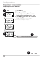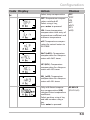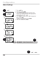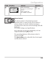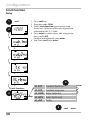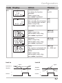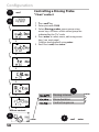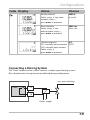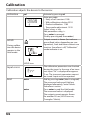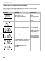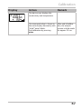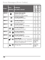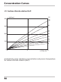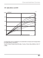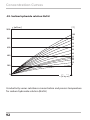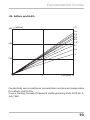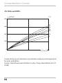
1
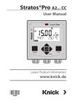
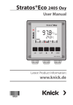
Stratos®Eco 2405 Cond User Manual Latest Product Information: www.knick.de Warranty Defects occurring within 3 years from delivery date shall be remedied free of charge at our plant (carriage and insurance paid by sender). Sensors, fittings, and accessories: 1 year. Subject to change without notice. Return of Products Under Warranty Please contact our Service Team before returning a defective device. Ship the cleaned device to the address you have been given. If the device has been in contact with process fluids, it must be decontaminated/disinfected before shipment. In that case, please attach a corresponding certificate, for the health and safety of our service personnel. Disposal Please observe the applicable local or national regulations concerning the disposal of “waste electrical and electronic equipment”. Knick Elektronische Messgeräte GmbH & Co. KG P.O. Box 37 04 15 D-14134 Berlin Phone: +49 (0)30 - 801 91 - 0 Fax: +49 (0)30 - 801 91 - 200 Internet: http://www.knick.de [email protected] 2 Table of Contents Safety Information.......................................................................... 5 Intended Use.....................................................................................................7 Registered Trademarks..................................................................................7 CD-ROM..............................................................................................................8 Safety Information..........................................................................................8 Short Instructions............................................................................................8 Overview of Stratos Eco 2405 Cond............................................ 9 Assembly.........................................................................................10 Package Contents..........................................................................................10 Mounting Plan................................................................................................11 Pipe Mounting, Panel Mounting..............................................................12 Installation and Connection........................................................14 Installation Instructions..............................................................................14 Terminal Assignments.................................................................................14 Wiring Examples . .........................................................................................16 Sensor Connection Using VP Cables......................................................20 Protective Wiring of Relay Outputs........................................................22 User Interface and Display..........................................................24 Operation: Keypad........................................................................26 Safety Functions............................................................................27 Sensocheck, Sensoface Sensor Monitoring.........................................27 GainCheck Device Self-Test.......................................................................27 Automatic Device Self-Test........................................................................27 Hold Mode.......................................................................................................28 Configuration.................................................................................30 Menu Structure of Configuration............................................................31 Overview of Configuration Steps............................................................32 Output 1...........................................................................................................34 Output 2...........................................................................................................46 3 Table of Contents Temperature Compensation.....................................................................52 Alarm Settings................................................................................................54 Limit Function.................................................................................................56 Controlling a Rinsing Probe.......................................................................58 Connecting a Rinsing System...................................................................59 Parameters......................................................................................60 Factory Settings of Parameters................................................................60 Parameters – Individual Settings.............................................................62 Calibration......................................................................................64 Calibration by Entry of Cell Constant.....................................................66 Calibration with Calibration Solution ...................................................68 Product Calibration .....................................................................................70 Temp Probe Adjustment..............................................................72 Measurement.................................................................................72 Diagnostics Functions..................................................................73 Error Messages (Error Codes)......................................................75 Operating States............................................................................77 Sensoface........................................................................................78 Appendix.........................................................................................81 Product Line and Accessories...................................................................81 Specifications..................................................................................................82 Calibration Solutions....................................................................................88 Concentration Curves..................................................................................90 Approvals – Canada......................................................................................96 CSA Control Drawing...................................................................................98 Index..............................................................................................100 Passcodes......................................................................................106 4 Safety Information Safety information – Be sure to read and observe the following instructions! The device has been manufactured using state of the art technology and it complies with applicable safety regulations. When operating the device, certain conditions may nevertheless lead to danger for the operator or damage to the device. Caution! Commissioning must be carried out by trained experts. Whenever it is likely that protection has been impaired, the device shall be made inoperative and secured against unintended operation. The protection is likely to be impaired if, for example: • the device shows visible damage • the device fails to perform the intended measurements • after prolonged storage at temperatures above 70°C • after severe transport stresses Before recommissioning the device, a professional routine test in accordance with EN 61010-1 must be performed. This test should be carried out at the manufacturer’s factory. Caution! Before commissioning, make sure that the transmitter may be connected with the other equipment. 5 6 Intended Use Stratos Eco 2405 Cond is used for measurement of electrical conductivity and temperature in liquids. Fields of application are: biotechnology, chemical industry, environment, food processing, water/waste-water treatment. The sturdy molded enclosure can be fixed into a control panel or mounted on a wall or at a post. The protective hood provides additional protection against direct weather exposure and mechanical damage. The device can be used with all 2- and 4-electrode sensors. It provides two current outputs (for transmission of measured value and temperature, for example), two contacts, and a universal power supply 24 ... 230 V AC/DC, AC: 45 ... 65 Hz. Registered Trademarks The following names are registered trademarks. For practical reasons they are shown without trademark symbol in this manual. Stratos® Sensocheck® Sensoface® GainCheck® 7 Provided Documentation CD-ROM Complete documentation: • Instruction manuals • Safety information • Short instructions Safety Information In official EU languages and others. • FM / CSA and Control Drawings • EC Declarations of Conformity Stratos® Eco 2405 Cond QuickStart Short Instructions.................................................. 3 Kurzübersicht ........................................................15 QuickStart ..............................................................27 Быстрый старт.....................................................39 Inicio rápido ..........................................................51 Início rápido ..........................................................63 Pikakäynnistys ......................................................75 Snabbstart..............................................................87 快速启动 ................................................................99 Other languages: www.knick.de 8 Short Instructions In German, English, French, Russian, Spanish, Portuguese, and Chinese. More languages on CD-ROM and on our website: www.knick.de • Installation and Commissioning • Operation • Menu structure • Calibration • Error messages and recommended actions Overview Overview of Stratos Eco 2405 Cond 2/4 El cond input Output 1 + Output 1 cond I hi 1 cond U hi 2 cond U lo 3 cond I lo 4 SG (solution ground) 5 Shield C 13 Relay RTD D 14 Not in use RTD E 9 10 – Output 1/2 Output 2 R1 Alarm 11 + Output 2 12 Relay 15 Alarm 16 Alarm 17 Clean Do not connect terminal ! Do not connect terminal ! Do not connect terminal ! 18 Clean 6 7 8 Power 19 Power supply 20 Power supply 9 Assembly Package Contents Check the shipment for transport damage and completeness. The package should contain: • Front unit • Rear unit • Bag containing small parts • CD-ROM with documentation • Specific test report • Passcode sticker 1 11 10 2 3 9 8 7 6 5 1 Jumper (2 x) 2 Washer (1 x), for conduit mounting: Place washer between enclosure and nut 3 Cable tie (3 x) 4 Hinge pin (1 x), insertable from either side 5 Enclosure screw (4 x) Fig.: Assembling the enclosure 10 4 6 Sealing insert (1 x) 7 Rubber reducer (1 x) 8 Cable gland (3 x) 9 Filler plug (3 x) 10 Hexagon nut (5 x) 11 Sealing plug (2 x), for sealing in case of wall mounting Assembly Mounting Plan 105 144 15 144 27 42 84 1 80 6,2 72 32 21 43 3 2 1 Cable gland (3 x) 2 Knockouts for cable gland or 1/2“ conduit, ø 21.5 mm (2 knockouts) Conduits not included! 3 Breakout for pipe mounting (4 x) 4 Breakout for wall mounting (2 x) 4 Fig.: Mounting plan (All dimensions in mm!) 11 Assembly Pipe Mounting, Panel Mounting 40 132 60 1 2 3 4 5 1 ZU 0276 protective hood (if required) 2 Hose clamp with worm gear drive to DIN 3017 (2 x) 3 Pipe-mount plate (1 x) 4 For vertical or horizontal posts or pipes 5 Self-tapping screw (4 x) Fig.: ZU 0274 pipe-mount kit (All dimensions in mm!) 165 132 173 1 Fig.: ZU 0276 protective hood for wall and pipe mounting (All dimensions in mm!) 12 1 Assembly max. 25 78 1 Screw (4 x) 2 Gasket (1 x) 3 Control panel 4 Span piece (4 x) 5 Threaded sleeve (4 x) 27 1 5 Panel cut-out 138 x 138 mm (DIN 43700) 4 2 1...22 3 Fig.: ZU 0275 panel-mount kit (All dimensions in mm!) 13 Installation and Connection Installation Instructions Caution! • Installation of the Stratos must be carried out by trained experts in accordance with this instruction manual and as per applicable local and national codes. • Be sure to observe the technical specifications and input ratings during installation. • Be sure not to notch the conductor when stripping the insulation. • Before connecting the device to the power supply, make sure that its voltage lies within the range 20.5 ... 253 V AC/DC. • All parameters must be set by a system administrator prior to commissioning. The terminals are suitable for single wires and flexible leads up to 2.5 mm2 (AWG 14). Caution! Additional safety precautions have to be taken for operation in hazardous locations CSA (CLI, DIV2, GPA,B,C,D T4, Ex nA IIC T4)! (See Appendix: Approvals)! Terminal Assignments Fig.: Stratos Eco 2405 Cond terminal assignments 14 Installation and Connection 3 2 1 1 Terminals for temperature probe and outer shield 2 Terminals for sensor 3 Terminals for power supply Fig.: Information on installation, rear side of device Division 2 Wiring The connections to the device must be installed in accordance with the National Electric Code (ANSI NFPA 70) Division 2 hazardous (classified) location non-incendive wiring techniques. 15 Wiring Examples Cond measurement with 4-electrode sensor Any 4-electrode sensors with cell constants from 0.0050 cm-1 to 19.9999 cm-1, with or without temperature detector, can be connected, e.g. SE600, SE603. RTD RTD shield SG I lo V lo V hi I hi Stratos Eco 2405 Cond Caution! Place jumper across terminals 4 and 5! When using a sensor with Solution Ground connection (SG) or a separate SG connection, the jumper is not required! Terminal 1 2 3 4 5 C D E Cell constant SE600 GY PK BU RD BN YE/GN WH/GN YE+GN 0.14...0.38 cm-1 SE603 GY PK BU RD * YE/GN WH/GN YE+GN 0.14...0.38 cm-1 * Connect external SG electrode (or tank wall) to terminal 5! 16 Wiring Examples Cond measurement with 2-electrode sensor (coaxial electrodes) Any 2-electrode sensors with cell constants from 0.0050 cm-1 to 19.9999 cm-1, with or without temperature detector, can be connected, e.g. SE610. Jumper RTD RTD shield SG I lo V lo V hi I hi Stratos Eco 2405 Cond Jumper Caution! Place jumpers: • across terminals 1 and 2 • across terminals 3 and 4 • across terminals 4 and 5 Terminal 2 (jumper 1-2) 3 (jumper 3-4-5) D E C Cell constant SE610 BN WH GN YE BK (shield) 0.1 cm-1 17 Wiring Examples Cond measurement with SE604 2-electrode sensor (coaxial electrodes) Connection using cable ZU 0645 (3 m), ZU 0569 (5 m), ZU 0570 (10 m) ZU 0589 (15 m), ZU 0590 (20 m), or ZU 0660 (30 m) Female connector Sensor cap 18 RTD RTD YE RD GN shield BK SG BU I lo GY V lo BN V hi PK WH I hi Stratos Eco 2405 Cond Wiring Examples Cond measurement with SE630 2-electrode sensor (formerly ZU 0071) Connection using included GDM connector with 5-m cable RTD RD/PK RTD GY shield BK SG I lo WH V lo GN V hi YE BN I hi Stratos Eco 2405 Cond GDM connector 19 Wiring Examples Sensor Connection Using VP Cables Connection diagrams for connecting conductivity sensors using VP cables (e.g. SE620) are provided on request. Any 2- or 4-electrode sensors with cell constants from 0.0050 cm-1 to 19.9999 cm-1, with or without temperature detector, can be connected. 20 21 Protective Wiring of Relay Outputs Protective Wiring of Relay Contacts Relay contacts are subjected to electrical erosion. Especially with inductive and capacitive loads, the service life of the contacts will be reduced. For suppression of sparks and arcing, components such as RC combinations, nonlinear resistors, series resistors and diodes should be used. 1 1 2 3 2 3 AC applications with inductive load 1 Load 2 RC combination, e.g. RIFA PMR 209 Typical RC combinations for 230 V AC: Capacitor 0.1 µF / 630 V Resistor 100 ohms / 1 W 3 Contact 22 Protective Wiring of Relay Outputs Typical Protective Wiring Measures A: DC application with inductive load B: AC/DC applications with capacitive load C: Connection of incandescent lamps A1Inductive load A2Free-wheeling diode, e.g. 1N4007 (Observe polarity) A3Contact B1 Capacitive load B2 Resistor, e.g. 8 Ω / 1 W at 24 V / 0.3 A B3 Contact C1 Incandescent lamp, max 60 W / 230 V, 30 W / 115 V C3 Contact Warning! Make sure that the maximum ratings of the relay contacts are not exceeded even during switching! 23 User Interface and Display User Interface 1 2 3 4 1 Display 2 Mode indicators (no keys), from left to right: - Measuring mode - Calibration mode - Alarm - Wash contact - Configuration mode 24 3 Alarm LED 4 Keypad User Interface and Display Display 1 2 3 4 5 6 7 20 8 9 10 11 19 12 18 13 17 16 15 1 Passcode entry 2 Not in use 3 Temperature 4 Current output 5 Limit values 6 Alarm 7 Sensocheck 8 calibration 9 Interval/response time 10 Wash contact 11 Measurement symbol 12 Press enter to proceed 13 Bar for identifying the device status, above mode indicators, from left to right: - Measuring mode - Calibration mode - Alarm - Not in use - Configuration mode 14 14 Secondary display 15 Manual temp specification 16 Hold mode active 17 Waiting time running 18 Sensor data 19 Main display 20 Sensoface 25 User Interface and Display Operation: Keypad cal conf enter Start, end calibration Start, end configuration • Select digit position (selected position blinks) • Menu navigation • Edit digit • Menu navigation • Calibration: Continue in program sequence • Configuration: Confirm entries, next configuration step • Measuring mode: Display output current cal enter Cal Info, display of calibration data enter Error Info: Display of last error message conf Start GainCheck device self-test + 26 Safety Functions Sensocheck, Sensoface Sensor Monitoring Sensocheck continuously monitors the sensor and its wiring. Sensocheck can be switched off (Configuration, Pg ��� ����). Sensoface provides information on the conductivity sensor condition. Significant sensor polarization effects or an excessive cable capacitance are indicated. GainCheck Device Self-Test A display test is carried out, the software version is displayed, and the memory and measured-value transfer are checked. Start GainCheck device self-test: + Automatic Device Self-Test The automatic device self-test checks the memory and measuredvalue transfer. It runs automatically in the background at fixed intervals. 27 Safety Functions Hold Mode Display: The Hold mode is a safety state during configuration and calibration. Output current is frozen (Last) or set to a fixed value (Fix). Alarm and limit contacts are disabled. If the calibration or configuration mode is exited, the device remains in the Hold mode for safety reasons. This prevents undesirable reactions of the connected peripherals due to incorrect configuration or calibration. The measured value and “HOLD” are displayed alternately. The device only returns to measuring mode after enter is pressed and 20 seconds have passed. Configuration mode is also exited automatically 20 minutes (timeout) after the last keystroke. The device returns to measuring mode. Timeout is not active during calibration. Behavior of output signal: Last: T he output current is frozen at its last value. Recommended for short configuration procedures. The process should not change decisively during configuration. Changes are not noticed with this setting! Fix: T he output current is set to a value that is noticeably different from the process value in order to signal the control system that the device is being worked at. See Configuration Pg 44. ��� 28 Safety Functions Alarm Alarm delay is 10 seconds. During an error message the alarm LED blinks. Error messages can also be signaled by a 22 mA output current. The alarm contact is activated by alarm or power failure, see also Pg 55. ��� 29 Configuration In the Configuration mode you set the device parameters. Activation conf Activate by pressing conf Enter passcode “1200“ Edit parameter using and , confirm/proceed using enter. (End by pressing conf, then enter.) HOLD The output current is frozen (at its last value or at a preset fixed value, depending on the configuration), limit and alarm contacts are inactive. Sensoface is off, “Configuration” mode indicator is on. During configuration the device remains in the Hold mode. HOLD icon Input errors End The configuration parameters are checked during the input. In the case of an incorrect input ”Err” is displayed for approx. 2 sec. The incorrect parameters cannot be stored. Input must be repeated. conf enter 30 End by pressing conf. The measured value and Hold are displayed alternately, “enter” blinks. Press enter key to end the Hold mode. The measured value is displayed. The output current remains frozen for another 20 sec (HOLD icon on, “hourglass” blinks). Configuration Menu Structure of Configuration The configuration steps are assigned to different menu groups. Using the arrow keys, you can jump between the individual menu groups. Each menu group contains menu items for setting the parameters. Pressing enter opens a menu item. The values are edited using the arrow keys. Pressing enter confirms/ saves the settings. Return to measurement: Press conf. Select menu group Menu group Code Output 1 o1. Display enter Menu item 1 Menu item 2 ... Menu item ... Output 2 o2. Temperature compensation tc. Alarm settings AL. Select menu item enter enter enter Relay Rinsing probes rL. Previous menu group: 31 Configuration Overview of Configuration Steps Code Menu Selection / Default out1 Output 1 o1.CELL Select sensor 2-electrode, 4-electrode o1.UnIT Select process variable μS, mS/cm, MΩ·cm, SAL, Conc o1.CoNC Select solution (Conc), see Pg 39 NaCl HCl NaOH H2SO4 HNO3 -1- Codes: -2- -3- o1.rNG Select current range 0-20 mA / 4-20 mA o1. 4mA Enter current start xxxx mS o1.20mA Enter current end xxxx mS o1.FtME Time constant of output filter xxxx SEC o1.FAIL 22 mA signal in the case of error ON / OFF o1.HoLD Signal behavior during HOLD Last / Fix o1.FIX Enter fixed value -4- xxx.x mA out2 Output 2 o2.UnIT Select temperature unit °C / °F o2. rTD Select temperature probe Pt100/Pt1000/NTC30 kΩ/ NTC8.55 kΩ o2.rNG Select current range 0-20 mA / 4-20 mA o2. 4mA Enter current start xxx.x o2.20mA Enter current end xxx.x o2.FtME Time constant of output filter xxxx SEC o2.FAIL 22 mA signal for temperature error ON / OFF o2.HoLD Signal behavior during HOLD Last / Fix o2.FIX Enter fixed value -5- xxx.x mA tc. Temperature Compensation tc. Select temp compensation OFF/Lin/nLF/NaCl/HCl/NH3 tc. LIN Lin: Enter temperature coefficient xx.xx %/K 32 Configuration Code Menu Selection / Default ALrt Alarm settings AL.SnSO Select Sensocheck rLAY Relay 1: Limit value L1.FCT Select contact function Lo / Hi L1.tYP Select contact response N/O / N/C L1.LEVL Enter setpoint xxxx L1.HYS Enter hysteresis xxxx L1.dLY Enter delay xxxx SEC Cn Cleaning probes Cn.InTV Rinse interval Cn.rins Rinse duration Cn.typ Contact response ON / OFF 33 Configuration Output 1 Selecting the sensor type 1 conf 2 Output 1: 1 Press conf key. 2 Enter passcode 1200. 3 Output 1 menu group is displayed. All items of this menu group are indicated by the “o1.” code. 4 Press enter to select menu, edit using arrow keys (see Pg ��� ����). Confirm (and proceed) using enter. 5 End: Press conf, then enter. 3 enter 4 o1.CELL o1.UnIT o1.CoNC o1.rNG o1.4mA o1.20mA o1.FtME o1.FAIL o1.HoLD Select sensor Select process variable Select solution (Conc) Select 0-20 / 4-20 mA Enter current start Enter current end Set output filter 22 mA for error HOLD mode 5 34 conf enter Configuration Code Display Action Selection o1. Select evaluation method: 2-electrode sensor / 4-electrode sensor Select usingkey, press enter to proceed. 2-El (2-El / 4-El) Note: Characters represented in gray are blinking and can be edited. 35 Configuration Output 1 Selecting the process variable 1 conf 2 Output 1: 1 Press conf key. 2 Enter passcode 1200. 3 Output 1 menu group is displayed. All items of this menu group are indicated by the “o1.” code. 4 Press enter to select menu, edit using arrow keys (see Pg ��� ����). Confirm (and proceed) using enter. 5 End: Press conf, then enter. 3 enter 4 o1.CELL o1.UnIT o1.CoNC o1.rNG o1.4mA o1.20mA o1.FtME o1.FAIL o1.HoLD Select sensor Select process variable Select solution (Conc) Select 0-20 / 4-20 mA Enter current start Enter current end Set output filter 22 mA for error HOLD mode 5 36 conf enter enter Configuration Code Display Action Choices o1. Select process variable: 000.0 mS (0.000 µS 00.00 μS 000.0 μS 0000 μS 0.000 mS 00.00 mS 000.0 mS 0.000 S/m 00.00 S/m 00.00 MΩ·cm 000.0 SAL 00.00 %) Select usingkey, press enter to proceed. Conductivity: 0.000 ... 9.999 μS/cm 00.00 ... 99.99 μS/cm 000.0 ... 999.9 μS/cm 0.000 ... 9.999 mS/cm 00.00 ... 99.99 mS/cm 000.0 ... 999.9 mS/cm 0.000 ... 9.999 S/m 00.00 ... 99.99 S/m Resistivity: 00.00 ... 99.99 MΩ·cm Salinity (SAL): 0.0 ... 45.0 ‰ (0 ... 35 °C) Concentration (Conc): 0.00 ... 9.99% by wt 37 Configuration Output 1 Concentration measurement: Select process solutions 1 conf 2 Output 1: 1 Press conf key. 2 Enter passcode 1200. 3 Output 1 menu group is displayed. All items of this menu group are indicated by the “o1.” code. 4 Press enter to select menu, edit using arrow keys (see Pg ��� ����). Confirm (and proceed) using enter. 5 End: Press conf, then enter. 3 enter 4 o1.CELL o1.UnIT o1.CoNC o1.rNG o1.4mA o1.20mA o1.FtME o1.FAIL o1.HoLD Select sensor Select process variable Select solution (Conc) Select 0-20 / 4-20 mA Enter current start Enter current end Set output filter 22 mA for error HOLD mode 5 38 conf enter enter Configuration Code Display Action Choices o1. Only with 00.00 % Conc can you select the process solution. Select using arrow key -01-SOL (-01-SOL -02-SOL -03-SOL -04-SOL -05-SOL) -01- NaCl (0.00 ... 9.99 % by wt) (0 ... 120 °C) -02- HCl (0.00 ... 9.99 % by wt) (-20 ... 50 °C) -03- NaOH (0.00 ... 9.99 % by wt) (0 ... 100 °C) -04- H2SO4 (0.00 ... 9.99 % by wt) (-17 ... 110 °C) -05- HNO3 (0.00 ... 9.99 % by wt) (-20 ... 50 °C) Press enter to proceed. Concentration Measurement For the solutions listed above, the device can determine the substance concentration from the measured conductivity and temperature values in % by wt. The measurement error is made up of the sum of measurements errors during conductivity and temperature measurement and the accuracy of the concentration curves stored in the device, see Pg �� ���. We recommend to calibrate the device together with the sensor. For exact temperature measurement, you should perform a temperature probe adjustment. For measuring processes with rapid temperature changes, use a separate temperature probe with fast response. 39 Configuration Output 1 Output current range, current start, current end 1 conf 2 Output 1: 1 Press conf key. 2 Enter passcode 1200. 3 Output 1 menu group is displayed. All items of this menu group are indicated by the “o1.” code. 4 Press enter to select menu, edit using arrow keys (see Pg ��� ����). Confirm (and proceed) using enter. 5 End: Press conf, then enter. 3 enter 4 o1.CELL o1.UnIT o1.CoNC o1.rNG o1.4mA o1.20mA o1.FtME o1.FAIL o1.HoLD Select sensor Select process variable Select solution (Conc) Select 0-20 / 4-20 mA Enter current start Enter current end Set output filter 22 mA for error HOLD mode 5 40 conf enter enter Configuration Code Display Action Choices o1. Set output current range Select usingkey, press enter to proceed. 4-20 mA (0 - 20 mA/ 4 - 20 mA) Current start Enter lower end of scale. Select usingkey, edit number using key, press enter to proceed. 000.0 mS (xxx.x mS) Current end Enter upper end of scale. Select usingkey, edit number using key, press enter to proceed. 100.0 mS (xxx.x mS) Assignment of Measured Values: Current Start and Current End Example 1: Range 0...200 mS/cm [mS/cm] Conductivity 200 Example 2: Range 100...200 mS/cm Advantage: Higher resolution in range of interest [mS/cm] Conductivity 200 Output current 0 Output current 100 4 20 [mA] 4 20 [mA] 41 Configuration Output 1 Time constant of output filter 1 conf 2 Output 1: 1 Press conf key. 2 Enter passcode 1200. 3 Output 1 menu group is displayed. All items of this menu group are indicated by the “o1.” code. 4 Press enter to select menu, edit using arrow keys (see Pg ��� ����). Confirm (and proceed) using enter. 5 End: Press conf, then enter. 3 enter 4 o1.CELL o1.UnIT o1.CoNC o1.rNG o1.4mA o1.20mA o1.FtME o1.FAIL o1.HoLD Select sensor Select process variable Select solution (Conc) Select 0-20 / 4-20 mA Enter current start Enter current end Set output filter 22 mA for error HOLD mode 5 42 conf enter enter Configuration Code Display Action Choices o1. Time constant of output filter 0 sec Default setting: 0 s (inactive). 0 ... 120 sec To specify a time constant: Select usingkey, edit number using key, press enter to proceed. Time Constant of Output Filter (Attenuation) To smoothen the current output, a low-pass filter with adjustable filter time constant can be switched on. When there is a jump at the input (100 %), the output level is at 63 % after the time constant has been reached. The time constant can be set from 0 to 120 sec. If the time constant is set to 0 sec, the current output follows the input. Please note: The filter only acts on the current output, not on the display or the limit value! Cond Time constant 0 ... 120 sec 43 Configuration Output 1 Output current during Error and HOLD 1 conf 2 Output 1: 1 Press conf key. 2 Enter passcode 1200. 3 Output 1 menu group is displayed. All items of this menu group are indicated by the “o1.” code. 4 Press enter to select menu, edit using arrow keys (see Pg ��� ����). Confirm (and proceed) using enter. 5 End: Press conf, then enter. 3 enter 4 o1.CELL o1.UnIT o1.CoNC o1.rNG o1.4mA o1.20mA o1.FtME o1.FAIL o1.HoLD Select sensor Select process variable Select solution (Conc) Select 0-20 / 4-20 mA Enter current start Enter current end Set output filter 22 mA for error HOLD mode 5 44 conf enter enter Configuration Code Display Action Choices o1. 22 mA signal for error message Select usingkey, press enter to proceed. OFF (OFF / ON) Output signal during HOLD LAST: During HOLD the last measured value is maintained at the output FIX: During HOLD a value (to be entered) is maintained at the output Select usingkey, press enter to proceed. LAST (LAST / FIX) Only with FIX selected: 21.0 mA Enter current which is to flow (00.0 ... at the output during HOLD 21.0 mA) Select position usingkey and edit number using key. Press enter to proceed. Output Signal During HOLD: Output current [mA] 21 Output signal HOLD Setting FIX = 21.0 mA Output signal HOLD Setting LAST 4 HOLD active HOLD active 45 Configuration Output 2 Temperature unit and probe, output current 1 conf 2 1 Press conf key. 2 Enter passcode 1200. 3 Select Output 2 menu group using arrow keys. All items of this menu group are indicated by the “o2.” code. 4 Press enter to select menu, edit using arrow keys (see Pg ��� ����). Confirm (and proceed) using enter. 5 End: Press conf, then enter. Output 2: 3 enter 4 o2.UnIT o2. rTD o2.rNG o2. 4mA o2.20mA o2.FtME o2.FAIL o2.HoLD 5 46 enter Select °C/°F Select temp probe Select 0-20 / 4-20 mA Enter current start Enter current end Set output filter 22 mA for temp error HOLD mode conf enter Configuration Code Display Action Choices o2. Specify temperature unit Select usingkey, press enter to proceed. °C (°C / °F) Select temperature probe Select usingkey, press enter to proceed. Pt100 (Pt1000, NTC30 kΩ, NTC8.55 kΩ) Select output current range Select usingkey, press enter to proceed. 4 - 20 mA (4 - 20 mA/ 0 - 20 mA) Current start: Enter lower end of scale. Select usingkey, edit number using key, press enter to proceed. 000.0 °C (xxx.x °C) Current start: Enter upper end of scale. Select usingkey, edit number using key, press enter to proceed. 100.0 °C (xxx.x °C) Process Temperature: Current Start and Current End Example 1: Range 0 ... 100 °C Example 2: Range 50 ... 70 °C Advantage: Higher resolution in range of interest [°C] Process temperature 100 [°C] Process temperature 70 Output current 0 Output current 50 4 20 [mA] 4 20 [mA] 47 Configuration Output 2 Time constant of output filter 1 conf 2 1 Press conf key. 2 Enter passcode 1200. 3 Select Output 2 menu group using arrow keys. All items of this menu group are indicated by the “o2.” code. 4 Press enter to select menu, edit using arrow keys (see Pg ��� ����). Confirm (and proceed) using enter. 5 End: Press conf, then enter. Output 2: 3 enter 4 o2.UnIT o2. rTD o2.rNG o2. 4mA o2.20mA o2.FtME o2.FAIL o2.HoLD 5 48 enter Select °C/°F Select temp probe Select 0-20 / 4-20 mA Enter current start Enter current end Set output filter 22 mA for temp error HOLD mode conf enter Configuration Code Display Action Choices o2. Time constant of output filter 0 sec Default setting: (0 ... 120 sec) 0 sec (inactive). To specify a time constant: Select using key, edit number using key, press enter to proceed. Time Constant of Output Filter To smoothen the current output, a low-pass filter with adjustable filter time constant can be switched on. When there is a jump at the input (100 %), the output level is at 63 % after the time constant has been reached. The time constant can be set from 0 to 120 sec. If the time constant is set to 0 sec, the current output follows the input. Please note: The filter only acts on the current output, not on the display! Cond Time constant 0 ... 120 sec 49 Configuration Output 2 Temperature error, output current during HOLD 1 conf 2 1 Press conf key. 2 Enter passcode 1200. 3 Select Output 2 menu group using arrow keys. All items of this menu group are indicated by the “o2.” code. 4 Press enter to select menu, edit using arrow keys (see Pg ��� ����). Confirm (and proceed) using enter. 5 End: Press conf, then enter. Output 2: 3 enter 4 o2.UnIT o2. rTD o2.rNG o2. 4mA o2.20mA o2.FtME o2.FAIL o2.HoLD 5 50 enter Select °C/°F Select temp probe Select 0-20 / 4-20 mA Enter current start Enter current end Set output filter 22 mA for temp error HOLD mode conf enter Configuration Code Display Action Choices o2. 22 mA signal for error message Select usingkey, press enter to proceed. OFF (OFF / ON) Output signal during HOLD LAST: During HOLD the last measured value is maintained at the output FIX: During HOLD a value (to be entered) is maintained at the output Select usingkey, press enter to proceed. LAST (LAST / FIX) Only with FIX selected: 21.0 mA Enter current which is to flow (00.0 ... at the output during HOLD 21.0 mA) Select position withkey and edit number with key. Press enter to proceed. Output Signal During HOLD: Output current [mA] Output signal HOLD Setting FIX = 21.0 mA Output signal HOLD Setting LAST 21 4 HOLD active HOLD active 51 Configuration Temperature Compensation Temp compensation selection 1 1 Press conf key. 2 Enter passcode 1200. 3 Select Temperature compensation menu group using arrow keys. All items of this menu group are indicated by the “tc.” code. 4 Press enter to select menu, edit using arrow keys (see Pg ��� ����). Confirm (and proceed) using enter. 5 End: Press conf, then enter. conf 2 Temp compensation: 3 enter 4 tc. Temp compensation 5 52 conf enter Configuration Code Display Action tc. Select temp compensation OFF: Temperature compensation switched off Select usingkey, press enter to proceed. LIN: Linear temperature compensation with entry of temperature coefficient and reference temperature Choices OFF (OFF LIN nLF nACL HCL nH3) nLF: Temperature compensation for natural waters to EN 27888 NaCl (nACL): Temperature compensation for ultrapure water with NaCl traces HCl (HCL): Temperature compensation for ultrapure water with HCl traces NH3 (nH3): Temperature compensation for ultrapure water with NH3 traces Only with linear temperature compensation (LIN) selected: Enter temperature coefficient. Select position usingkey and edit number using key. Press enter to proceed. 02.00%/K (XX.XX %/K) 53 Configuration Alarm Settings 1 conf 2 1 Press conf key. 2 Enter passcode 1200. 3 Select Alarm settings menu group using arrow keys. All items of this menu group are indicated by the “AL.” code. 4 Press enter to select menu, edit using arrow keys (see Pg ��� ����). Confirm (and proceed) using enter. 5 End: Press conf, then enter. Alarm settings: 3 4 enter AL.SnSO Select Sensocheck 5 54 conf enter Configuration Code Display Action Choices AL. Select Sensocheck (continuous monitoring of sensor) Select usingkey, press enter to proceed. OFF (ON / OFF) Alarm 15 16 Alarm Contact The alarm contact is closed during normal operation (N/C). It opens in the case of alarm or power outage. As a result, a failure message is provided even in the case of line breakage (fail-safe behavior). For contact ratings, see Specifications. Error messages can also be signaled by a 22 mA output current (see Pg ��� ����, ��, ���). The operating behavior of the alarm contact is shown on Pg �� ���. The alarm delay acts on the LED, the 22 mA signal and the alarm contact. 55 Configuration Limit Function Relay 1 conf 2 1 Press conf key. 2 Enter passcode 1200. 3 Select Limit function menu group using arrow keys. All items of this menu group are indicated by the “L1.” code. 4 Press enter to select menu, edit using arrow keys (see Pg ��� ����). Confirm (and proceed) using enter. 5 End: Press conf, then enter. 4 Limit function: 3 L1.FCT L1.tYP L1.LEVL enter L1.HYS L1.dLY 5 56 enter Contact function Contact response Enter setpoint Enter hysteresis Delay conf enter Configuration Code Display Action Choices L1. Contact function (see below for function principle) Select usingkey, press enter to proceed. Lo (Lo/Hi) Contact response N/O N/C: normally closed contact (N/O N/O: normally open contact N/C) Select usingkey, press enter to proceed. Setpoint Select usingkey, edit number using key, press enter to proceed. 000.0 mS (xxx.x mS) Hysteresis Select usingkey, edit number using key, press enter to proceed. 001.0 mS (xxx.x mS) Delay The contact is activated with delay (deactivated without delay) Select usingkey, edit number using key, press enter to proceed. 0010 sec (0 ... 9999 sec) Limit Hi Limit Lo Signal Signal Hysteresis + Setpoint Setpoint Hysteresis - 1 contact 1 contact 0 0 57 Configuration 1 conf 2 Controlling a Rinsing Probe “Clean” contact 1 Press conf key. 2 Enter passcode 1200. 3 Select Rinsing Limit function probesmenu menugroup groupusing using arrow keys. All items of this menu group are indicated by the “Cn. “rL.””code. code. 4 Press enter to select menu, edit using arrow keys (see Pg next 58).page). Confirm (and proceed) using enter. 5 End: Press conf, then enter. 4 enter Rinsing interval Rinse duration Contact response Rinse contact: 3 enter 58 5 conf enter Configuration Code Display Action Choices Rinsing interval Select using key, enter number using , press enter to proceed. 0000 h (x.xxx h) Rinse duration Select using key, enter number using , press enter to proceed. 0060 sec (xxxx sec) Contact response N/C N/C: normally closed contact (N/O) N/O: normally open contact Select using , press enter to proceed. Connecting a Rinsing System The “Clean” contact can be used to connect a simple spray cleaning system. Rinse duration and rinsing interval are defined during configuration. e.g. spray cleaning Clean 17 18 Power supply 59 Parameters Factory Settings of Parameters Activation: Simultaneously press conf + right arrow key and enter passcode “4321“. The lower display line reads “Clear“. To prevent accidental resetting, “NO“ is set as default (blinking in the main display). Press one of the arrow keys to select “YES“ and confirm by pressing enter. Caution! Your data (also calibration data) will be overwritten by the factory settings! Code Parameters Factory setting o1.CELL Select sensor 2-EL o1.UnIT Process variable 000.0 mS o1.CoNC Conc solution -01- o1. rNG 0/4-20 mA 4-20 mA o1. 4mA Current start 000.0 mS o1.20mA Current end 100.0 mS o1.FtME Filter time 0s o1.FAIL 22mA signal OFF o1.HoLD HOLD response Last o1.FIX Fix current 021.0 mA o2.UnIT Unit °C / °F °C o2.rTD Temp probe Pt100 o2.rNG 0/4-20 mA 4-20 mA o2. 4mA Current start 000.0 °C o2.20mA Current end 100.0 °C o2.FtME Filter time 0s o2.FAIL 22mA signal OFF o2.HoLD HOLD response Last o2.FIX Fix current 021.0 mA 60 Parameters Code Parameters Factory setting tc. Temp compensation OFF tc. LIN Temp coefficient 02.00%/K AL.SnSO Sensocheck OFF L1.FCT Contact function Lo L1.tYP Contact response N/O L1.LEVL Setpoint 000.0 mS L1.HYS Hysteresis 001.0 mS L1.dLY Delay 0010 sec Rinsing interval Rinse duration Contact type Please note: Fill in your configuration data on the following pages. Please note: The cell constant is factory set to 1.0000 cm-1. 61 Parameters Parameters – Individual Settings Code Parameter o1.CELL Sensor o1.UnIT Process variable o1.CoNC Solution (Conc) o1. rNG 0/4-20 mA o1. 4mA Current start o1.20mA Current end o1.FtME Filter time o1.FAIL 22mA signal o1.HoLD HOLD response o1.FIX Fix current o2.UnIT Unit °C / °F o2.rTD Temp probe o2.rNG 0/4-20 mA o2. 4mA Current start o2.20mA Current end 62 Setting Parameters Code Parameter o2.FtME Filter time o2.FAIL 22mA signal Setting o2.HoLD HOLD response o2.FIX Fix current tc. Temp compensation tc. LIN Temp coefficient AL.SnSO Sensocheck L1.FCT Contact function L1.tYP Contact response L1.LEVL Setpoint L1.HYS Hysteresis L1.dLY Delay Rinsing interval Rinse duration Contact type 63 Calibration Calibration adjusts the device to the sensor. cal Activate by pressing cal Activation Enter passcode: • Entry of cell constant 1100 • With calibration solution 0110 • Product calibration 1105 • Temp probe adjustment 1015 Select using key. Edit parameter using . Press enter to proceed. (End by pressing cal, then enter.) HOLD Output current is frozen (last value or preset fixed value, depending on configuration), limit and alarm contacts are inactive. Sensoface is off, “Calibration” mode indicator is on. During calibration the device remains in the Hold mode. HOLD icon Input errors End The calibration parameters are checked during the input. In the case of an incorrect input ”Err” is displayed for approx. 2 sec. The incorrect parameters cannot be stored. Input must be repeated. enter enter 64 End by pressing enter (abort using cal). The measured value and Hold are displayed alternately, “enter” blinks. Sensoface is active. Press enter to end the Hold mode. The measured value is displayed. The output current remains frozen for another 20 sec (HOLD icon on, “hourglass” blinks). Calibration Information on Calibration Calibration adapts the device to the conductivity sensor. Calibration can be performed by: • Input of cell constant (e.g. for ultrapure-water sensors) • Determining the cell constant with a known calibration solution (conductivity standard) • Product calibration (calibration by comparison) • Temperature probe adjustment Please note: • All calibration procedures must be performed by trained personnel. • Incorrectly set parameters may go unnoticed, but change the measuring properties. 65 Calibration Calibration by Entry of Cell Constant Input of cell constant with simultaneous display of uncorrected conductivity value and temperature Display Action Remark Press cal key, enter code 1100. Select using key, edit number using key, press enter to proceed. Device is in the Hold mode. If an invalid code is entered, the device returns to measuring mode. Ready for calibration Display (2 sec) Enter cell constant of connected sensor: The lower display shows the measured conductivity value. (When there has not been an entry for 6 sec, the lower display alternately shows the conductivity and temperature value.) Select using, enter number using A change in the cell constant also changes the conductivity value. Press enter to confirm cell constant. 66 Calibration Display Action Remark The device now displays the conductivity and temperature. The measured value is shown in the main display alternately with “Hold”, “enter” blinks. End calibration by pressing enter. After end of calibration, the outputs remain in Hold mode for approx. 20 sec. 67 Calibration Calibration with Calibration Solution Input of temperature-corrected value of calibration solution (calibration standard) with simultaneous display of cell constant Display Action Remark Press cal key, enter code 0110. Select using key, edit number using key, press enter to proceed. Device is in the Hold mode. If an invalid code is entered, the device returns to measuring mode. Ready for calibration Display (2 sec) Remove and clean sensor Immerse sensor in calibration solution. Determine the temperaturecorrected conductivity value of the calibration solution from the corresponding table (see Pg 86). Enter value of calibration solution. Select usingkey, edit number using key. Press enter to confirm the calibration. 68 When there has not been an entry for 6 sec, the lower display alternately shows the cell constant and temperature value. The cell constant and temperature are alternately displayed in the lower display during the input. Calibration Display Action Remark The determined cell constant is displayed. Press enter to confirm. The device now displays the conductivity and temperature. Clean sensor and re-place it in the process. The measured value is shown in the main display alternately with “Hold”. “enter” blinks. End calibration by pressing enter. After end of calibration, the outputs remain in Hold mode for approx. 20 sec. Please note: • Be sure to use known calibration solutions with the respective temperature-corrected conductivity values (see ”Calibration Solutions” Pg 88 ������������� et seq.��� ). • Make sure that the temperature does not change during the calibration procedure. 69 Calibration Product Calibration Calibration by comparison For product calibration the measured variable is used as configured: conductivity (µS/cm, mS/cm, S/m), resistivity (MΩ·cm). During product calibration the sensor remains in the process. The measurement is only interrupted briefly. Calibration is without TC correction. Procedure: The currently measured value is stored in the device for comparison. A sample is measured using a portable meter. The sample value is then entered in the device. The new cell constant is calculated from these two values. Display Action Remark Press cal key, enter code 1105. Presskey to select position, enter number usingkey, press enter to confirm. If an invalid code is entered, the device returns to measuring mode. Display (approx. 2 sec) Save currently measured value. Press enter to proceed. 70 Perform reference measurement. Calibration Display Action Remark Enter sample value. The new cell constant is calculated. The determined cell constant is displayed. Press enter to confirm. New calibration: Press cal. The new value is shown in the main display alternately with “Hold”, “enter” blinks. End by pressing enter. After end of calibration, the outputs remain in Hold mode for approx. 20 sec. 71 Temp Probe Adjustment Display Action Remark Select calibration Press cal key, enter code 1015. Presskey to select position, enter number usingkey, press enter to confirm. Wrong settings change the measurement properties! If an invalid code is entered, the device returns to measuring mode. Ready for calibration Measure the temperature of the process medium using an external thermometer Device is in Hold mode. Display approx. 2 sec Enter measured temperature value. Select usingkey, edit number using key, press enter to proceed. End adjustment by pressing enter. HOLD will be deactivated after 20 sec. Default: Value of secondary display. Measurement Display Action In the measuring mode the main display shows the configured process variable (conductivity, resistivity, or SAL) and the lower display the temperature. During calibration you can return to measuring mode by pressing the cal key, during configuration by pressing conf (waiting time for signal stabilization approx. 20 sec). 72 Diagnostics Functions Display Action Display of output currents Press enter while in measuring mode. The current at output 1 is shown in the main display, the current at output 2 in the secondary display. After 5 sec the device returns to measuring mode. Display of calibration data (Cal Info) Press cal while in measuring mode and confirm code 0000. The current cell constant is shown in the main display. After 20 sec the device returns to measuring mode (immediate return at pressing enter). Sensor monitor for validation of sensor and complete signal processing. Press conf while in measuring mode and enter code 2222. The measured resistance is shown in the main display, the measuring temperature in the lower display. Press enter to return to measurement. Display of last error message (Error Info) Press conf while in measuring mode and confirm code 0000. The last error message is displayed for approx. 20 sec. After that the message will be deleted (immediate return to measurement at pressing enter). 73 Diagnostics Functions These functions are used for testing the connected peripherals. Display Action Specify current at output 1 Press conf while in measuring mode, enter code 5555. The current indicated in the main display for output 1 can be edited. Select usingkey, edit number usingkey. Press enter to confirm entry. The entered value will be shown in the secondary display. The device is in Hold mode. Press conf, then enter to return to measurement (Hold remains active for another 20 sec). Specify current at output 2 Press conf while in measuring mode, enter code 5556. The current indicated in the main display for output 2 can be edited. Select usingkey, edit number usingkey. Press enter to confirm entry. The entered value will be shown in the secondary display. The device is in Hold mode. Press conf, then enter to return to measurement (Hold remains active for another 20 sec). 74 Red LED Out 1 (22 mA) ERR 01 Measured Sensor x x x ERR 02 Measured Unsuitable sensor x x x ERR 98 “Conf“ System error x x x x ERR 99 “FAIL” Factory settings x x x x Error Display value blinks value blinks blinks blinks Problem Possible causes • • • • Out 2 (22 mA) Alarm contact Error Messages (Error Codes) Wrong cell constant Measuring range violation SAL > 45 ‰ Sensor connection or cable defective Conductance range > 3500 mS Configuration or calibration data defective; completely reconfigure the device using the factory settings. Then calibrate. Memory error in device program EEPROM or RAM defective This error message only occurs in the case of a total defect. The device must be repaired and recalibrated at the factory. 75 Alarm contact Red LED Out 1 (22 mA) Out 2 (22 mA) Error Messages (Error Codes) ERR 03 Temperature probe x x x x ERR 11 Current output 1 x x x ERR 12 Current output 1 x x x ERR 13 Current output 1 x x x ERR 21 Current output 2 x x x ERR 22 Current output 2 x x x ERR 23 Current output 2 x x x ERR 33 Sensocheck: x x Error 76 Icon Problem (blinks) Possible causes Open or short circuit Temperature range exceeded Current below 0 (3.8) mA Current above 20.5 mA Current span too small / too large Current below 0 (3.8) mA Current above 20.5 mA Current span too small / too large x Wrong or defective sensor / polarization effects at the sensor / cable too long or defective / plug defective Sensoface active, see Pg �� 79 Temperature outside conversion tables (TC, conc, SAL) Sensoface active, see Pg �� 79 Timeout Cleaning contact Relay 1 limit value Alarm contact Out 2 Operating status Out 1 Operating States Measure Cal Info (cal) 0000 20 s Error Info (conf ) 0000 20 s Calibration (cal) 1100 Temp adjustment (cal) 1015 Product calibration (cal) 1105 Configuration (conf ) 1200 20 min Sensor monitor (conf ) 2222 20 min Current source 1 (conf ) 5555 20 min Current source 2 (conf ) 5556 20 min Rinsing function active as configured (Last/Fix or Last/Off ) 77 Sensoface The smiley in the display (Sensoface) provides information about the sensor condition (defects, maintenance required, cable capacitance too high). It alerts to significant sensor polarization or excessive cable capacitance e.g. caused by an unsuitable cable or a cable that is too long. The permitted calibration ranges and the conditions for a friendly, neutral, or sad Sensoface are summarized in the following chart. Additional icons refer to the error cause. Sensocheck Continuously monitors the sensor and its wiring. Sensocheck can be switched off. Critical values make the Sensoface “sad” and the corresponding icon blinks: The Sensocheck message is also output as error message Err 33. The alarm contact is active, the red LED is lit, output current 1 is set to 22 mA (when configured correspondingly). Sensocheck can be switched off during configuration (then Sensoface is also disabled). Exception: After a calibration a smiley is always displayed for confirmation. Notice The worsening of a Sensoface criterion leads to the devaluation of the Sensoface indicator (Smiley becomes “sad”). An improvement of the Sensoface indicator can only take place after calibration or removal of the sensor defect. 78 Sensoface Display Problem Status Sensor defect Wrong or defective sensor Significant polarization of sensor Excessive cable capacitance (see also Err 33, Error Messages on Pg ���� ���). Temperature error Temperature outside range for TC, conc, SAL Please note: When very fast response times (t90) are required, e.g. when detecting separation layers, Sensocheck should be switched off (see “Specifications” Pg ��� ����). 79 80 Appendix Product Line and Accessories Devices Order No. Stratos Eco 2405 Cond 2405 Cond Mounting Accessories Pipe-mount kit ZU 0274 Panel-mount kit ZU 0275 Protective hood ZU 0276 Input socket for a Pt 100/Pt 1000 with Schott 9908 screwed plug ZU 0165 Connector for power supply instead of cable gland, Harting HAN 7D, with male insert ZU 0271 Connector for current output instead of cable gland, Harting HAN 8U, ZU 0272 with female insert For more information concerning our sensors and fittings product line, please refer to our “Sensors, Fittings, Accessories” catalog: Download at http://www.knick.de or request catalog: Phone: +49 (0)30 - 801 91 - 0 Fax: +49 (0)30 - 801 91 - 200 E-mail: [email protected] 81 Specifications Conductivity input Input for 2-electrode/4-electrode sensors Effective range Conductivity 0.2 µS · c ... 1000 mS · c Measuring ranges Conductivity 0.000 ... 9.999 μS/cm 00.00 ... 99.99 μS/cm 000.0 ... 999.9 μS/cm 0000 ... 9999 μS/cm 0.000 ... 9.999 mS/cm 00.00 ... 99.99 mS/cm 000.0 ... 999.9 mS/cm 0,000 ... 9.999 S/m 00.00 ... 99.99 S/m Response time (T90) Resistivity 00.00 ... 99.99 MΩ · cm Concentration 0.00 ... 9.99 % by wt Salinity 0.0 ... 45 ‰ (0 ... 35 °C) < 1 s (Sensocheck off ) < 3 s (Sensocheck on) Meas. error 1,2,3) < 1 % meas. val. + 0.4 µS · c Concentration determination Operating modes * -01- NaCl 0.00...9.99 % by wt (0...60 °C) -02- HCl 0.00...9.99 % by wt (-20...50 °C) -03- NaOH 0.00...9.99 % by wt (0...100 °C) -04- H2SO4 0.00...9.99 % by wt (-17...110 °C) -05- HNO3 0.00...9.99 % by wt (-20...50 °C) See graphs in the Appendix, Pg 90 82 Specifications Sensor standardization Operating modes • Input of cell constant with simultaneous display of conductivity and temperature • Input of conductivity of calibration solution with simultaneous display of cell constant and temperature • Product calibration • Temperature probe adjustment Adm. cell constant 00.0050 ... 19.9999 cm-1 Sensor monitoring Sensocheck Polarization detection and monitoring of cable capacitance Sensoface Provides information on the sensor condition (Sensocheck) Sensor monitor Direct display of measured values from sensor for validation (resistance/temperature) Temperature input * Pt100/Pt1000/NTC 30 kΩ/NTC 8.55 kΩ (Betatherm) 2-wire connection, adjustable Measuring range Pt 100/Pt 1000 -20.0 ... +200.0 °C (-4...+392 °F) NTC 30 kΩ -20.0 ... +150.0 °C (-4...+302 °F) NTC 8.55 kΩ -10.0 ... +130.0 °C (+14...+266 °F) Resolution Meas. error 0.1 °C / 0.1 °F 1,2,3) < 0.5 K (< 1K for Pt100; < 1K for NTC > 100°C) 83 Specifications Temperature compensation (OFF) Without (reference temp 25°C) (Lin) Linear characteristic 00.00 ... 19.99 %/K (NLF) Natural waters to EN 27888 (nACL) Ultrapure water with NaCl traces (0...120°C) (HCL) Ultrapure water with HCl traces (0...120°C) (nH3) Ultrapure water with NH3 traces (0...120°C) Output 1 0/4 ... 20 mA, max. 10 V, floating (galvanically connected to output 2) Process variable* Overrange Conductivity, resistivity, concentration, salinity * Output filter 22 mA in the case of error messages * Low-pass, filter time constant 0 ... 120 s Measurement error 1) < 0.3% current value + 0.05 mA Start/end of scale As desired within range Minimum span 5 % of selected range Output 2 0/4 ... 20 mA, max. 10 V, floating (galvanically connected to output 1) Process variable Temperature Overrange * 22 mA in case of temp error messages Output filter * Low-pass, filter time constant 0 ... 120 s Measurement error Start/end of scale * 1) < 0.3% current value + 0.05 mA –20 ... 300 °C / –4 ... 572 °F Admissible span 20 ... 320 K / 36 ... 576 °F Alarm contact Relay contact, floating Contact ratings AC< 250 V / < 3 A / < 750 VA DC< 30 V / < 3 A / < 90 W Contact response N/C (fail-safe type) Alarm delay 10 s 84 Specifications Limit values Output via relay contact Contact ratings AC< 250 V / < 3 A / < 750 VA DC< 30 V / < 3 A / < 90 W Contact response* N/O or N/C Delay * 0000 ... 9999 s Setpoints* Hysteresis * As desired within range 0 ... 50 % full scale Cleaning function Relay contact, floating, for controlling a simple rinsing system or an automatic cleaning system Contact ratings AC< 250 V / < 3 A / < 750 VA DC< 30 V / < 3 A / < 90 W Contact response N/C or N/O Rinse interval 000.0 ... 999.9 h (000.0 h = cleaning function switched off ) Rinse duration 0000 ... 1999 s Display LC display, 7-segment with icons Main display Character height 17 mm, unit symbols 10 mm Secondary display Character height 10 mm, unit symbols 7 mm Sensoface 3 status indicators (friendly, neutral, sad face) Mode indication 4 mode indicators “meas“, “cal“, “alarm“, “config“ Further icons for configuration and messages Alarm indication Red LED in case of alarm Keypad 5 keys: [cal] [conf ] [] [] [enter] Service functions Current source Current specifiable for output 1 and 2 (00.00 ... 22.00 mA) Device self-test Automatic memory test (RAM, FLASH, EEPROM) Display test Display of all segments 85 Specifications Last Error Display of last error occurred Sensor monitor Display of direct sensor signal (resistance/temperature) Data retention Parameters and calibration data > 10 years (EEPROM) Protection against electric shock Safe electrical isolation of all extra-low-voltage circuits against mains by double insulation to EN 61010-1 Power supply 24 (-15%)...230 V AC/DC (+10%); appr. 5 VA, 2.5 W AC: 45 ... 65 Hz Overvoltage category II, protection class II Nominal operating conditions Ambient temperature –20 ... +55 °C Transport/Storage temp –20 ... +70 °C Relative humidity 80 % at temperatures up to 55 °C, maximum operating height 2000 m Power supply 24 (–15%) ... 230 V AC/DC (+10%) Frequency for AC 45 ... 65 Hz EMC EN 61326-1, EN 61326-2-3 Emitted interference Class B (residential area) Class A for mains > 60 V DC Immunity to interference Industry Explosion protection FM NI Class I Div 2 Group A, B, C & D, T4 Ta = 55 °C; Type 2 NI Class I Zone 2 Group IIC, T4 Ta = 55°C; Type 2 CSA Class I Div 2 Groups A, B, C and D, T4 Ex nA IIC T4 86 Specifications Housing Molded enclosure made of PBT (polybutyleneterephtalate) Color Bluish gray RAL 7031 Mounting • Wall mounting • Pipe mounting: Ø 40 ... 60 mm • Panel mounting, cutout to DIN 43 700 Sealed against panel Dimensions H 144 mm, W 144 mm, D 105 mm Ingress protection IP 65 / NEMA 4X Cable glands 3 knockouts for cable glands M20x1.5 2 knockouts for NPT 1/2" or rigid metallic conduit Weight Approx.1 kg 30 ... 45 mm * User-defined 1) To IEC 746 Part 1, at nominal operating conditions 2) ± 1 count 3) Plus sensor error 87 Calibration Solutions Potassium Chloride Solutions (Conductivity in mS/cm) Temperature Concentration 1) °C 0.01 mol/l 0 5 10 15 16 17 18 19 20 21 22 23 24 25 26 27 28 29 30 31 32 33 34 35 36 0.776 0.896 1.020 1.147 1.173 1.199 1.225 1.251 1.278 1.305 1.332 1.359 1.386 1.413 1.441 1.468 1.496 1.524 1.552 1.581 1.609 1.638 1.667 1.696 0.1 mol/l 7.15 8.22 9.33 10.48 10.72 10.95 11.19 11.43 11.67 11.91 12.15 12.39 12.64 12.88 13.13 13.37 13.62 13.87 14.12 14.37 14.62 14.88 15.13 15.39 15.64 1 mol/l 65.41 74.14 83.19 92.52 94.41 96.31 98.22 100.14 102.07 104.00 105.94 107.89 109.84 111.80 113.77 115.74 1) D ata source: K. H. Hellwege (Editor), H. Landolt, R. Börnstein: Zahlenwerte und Funktionen ..., volume 2, part. volume 6 2) Data source: Test solutions calculated according to DIN IEC 746-3 88 Calibration Solutions Sodium Chloride Solutions (Conductivity in mS/cm) Temperature Concentration °C 0.01 mol/l2) 0.1 mol/l2) 0 1 2 3 4 5 6 7 8 9 10 11 12 13 14 15 16 17 18 19 20 21 22 23 24 25 26 27 28 29 30 31 32 33 34 35 36 0.631 0.651 0.671 0.692 0.712 0.733 0.754 0.775 0.796 0.818 0.839 0.861 0.883 0.905 0.927 0.950 0.972 0.995 1.018 1.041 1.064 1.087 1.111 1.135 1.159 1.183 1.207 1.232 1.256 1.281 1.306 1.331 1.357 1.382 1.408 1.434 1.460 5.786 5.965 6.145 6.327 6.510 6.695 6.881 7.068 7.257 7.447 7.638 7.831 8.025 8.221 8.418 8.617 8.816 9.018 9.221 9.425 9.631 9.838 10.047 10.258 10.469 10.683 10.898 11.114 11.332 11.552 11.773 11.995 12.220 12.445 12.673 12.902 13.132 Saturated1) 134.5 138.6 142.7 146.9 151.2 155.5 159.9 164.3 168.8 173.4 177.9 182.6 187.2 191.9 196.7 201.5 206.3 211.2 216.1 221.0 226.0 231.0 236.1 241.1 246.2 251.3 256.5 261.6 266.9 272.1 277.4 282.7 288.0 293.3 298.7 304.1 309.5 89 Concentration Curves -01- Sodium chloride solution NaCl [°C] [°C] χ [mS/cm] 400 100 82 300 60 46 200 35 20 10 0 100 0 0 5 [Gew%] cc [% by wt] 10 Conductivity versus substance concentration and process temperature for sodium chloride solution (NaCl) 90 Concentration Curves -02- Hydrochloric acid HCl [°C] [°C] χ [mS/cm] 1000 50 40 800 30 25 20 600 10 0 400 200 0 0 5 [Gew%] cc [% by wt] 10 Conductivity versus substance concentration and process temperature for hydrochloric acid (HCl) Source: Haase/Sauermann/Dücker; Z. phys. Chem. New Edition, Vol. 47 (1965) 91 Concentration Curves -03- Sodium hydroxide solution NaOH χ [mS/cm] 1000 [°C] [°C] 100 90 80 800 70 60 600 50 40 400 30 25 20 10 0 200 0 5 [Gew%] cc [% by wt] 10 Conductivity versus substance concentration and process temperature for sodium hydroxide solution (NaOH) 92 Concentration Curves -04- Sulfuric acid H2SO4 [°C] [°C] χ [mS/cm] 600 93,3 82,2 71,1 60,0 48,9 37,8 400 26,7 15,6 4,4 200 0 0 5 [Gew%] cc [% by wt] 10 Conductivity versus substance concentration and process temperature for sulfuric acid (H2SO4) Source: Darling; Journal of Chemical and Engineering Data; Vol.9 No. 3, July 1964 93 Concentration Curves -05- Nitric acid HNO3 [°C] [°C] χ [mS/cm] 800 50 40 600 30 20 400 10 0 200 0 0 5 cc [Gew%] [% by wt] 10 Conductivity versus substance concentration and process temperature for nitric acid (HN03) Source: Haase/Sauermann/Dücker; Z. phys. Chem. New Edition, Vol. 47 (1965) 94 Glossary Conductance Conductance G [S] = 1 / R [Ω] Conductivity Conductivity χ [S/cm] = G [S] · c [1/cm] Conductivity sensor Either 2- or 4-electrode sensors can be connected. The cell constant of the sensor in use must be entered or be determined using a calibration solution taking account of the temperature. A special device variant (Stratos Eco 2405 CondI) is provided for electrodeless sensors. Passcode Preset four-digit number to select certain functions. Sensocheck Sensocheck monitors the sensor and its wiring. The resulting information is indicated by the Sensoface smileys. Sensocheck can be switched off. Sensoface Provides information on the sensor condition. Significant sensor polarization effects or an excessive cable capacitance are indicated.. Temperature coefficient With temperature compensation activated, the measured value is calculated to the value at the reference temperature (25 °C) using the temperature coefficient. Temperature compensation Calculates the measured conductivity value for a reference temperature. 95 Approvals – Canada Warnings and Notes to Ensure Safe Operation Warning! Do not disconnect equipment unless power has been switched off. Caution! Clean only with antistatic moistened cloth. Caution! Substitution of components may impair suitability for hazardous locations. • The equipment shall be installed and protected from mechanical impact and ultraviolet (UV) sources. • Clean only with a moistened antistatic cloth as potential electro static hazard may exist. Service equipment only with conductive clothing, footwear and personal grounding devices to prevent electrostatic accumulation. • Internal grounding provisions shall be provided for field wiring. Bonding between conduit shall be provided during installation, and all exposed non-current carrying metallic parts shall be bonded and grounded. • Installation in a Class I, Division 2 or Class I, Zone 2 hazardous location shall be in accordance with the Canadian Electrical Code (CEC Part 1) Section 18 Division 2 wiring methods. • The equipment shall have a switch or circuit breaker in the building installation (that is in close proximity to the equipment) that is marked as the disconnect switch. • The enclosure Type 2 is only for indoor use. • The mains supply voltage fluctuations should not exceed -15/+10 percent of the nominal supply voltage. • The device shall not be used in a manner not specified by this manual. 96 Approvals – Canada Caution! Use supply wires suitable for 30 °C above ambient and rated at least 250 V. Caution! Use signal wires suitable for at least 250V. OBSERVE THE SPECIFICATIONS OF THE CONTROL DRAWING! 97 Approvals – Canada CSA Control Drawing 98 Approvals – Canada 99 Index 22 mA signal for error message 45, 51 A Accessories 81 Alarm contact 55, 84 Alarm setings 29, 54 Approvals 96 Assembly 10 C Calibration 64 by entry of cell constant 66 Product calibration 70 Temp probe adjustment 72 with calibration solution 68 Calibration solutions 88 Cal Info 73 “Clean” contact 58 Concentration curves 90 Hydrochloric acid HCl 91 Nitric acid HNO3 94 Sodium chloride solution NaCl 90 Sodium hydroxide solution NaOH 92 Sulfuric acid H2SO4 93 Concentration measurement 39 Configuration 30 Menu structure 31 Configuration: Alarm settings 54 Configuration: Limit function 56, 58 Configuration: Output 1 Concentration measurement 38 Output current during Error and HOLD 44 Output current range 40 Output filter 42 Process variable 36 Sensor type 34 100 Index Configuration: Output 2 Output current 46 Output current during HOLD 50 Output filter 48 Temperature 46 Temperature error 50 Configuration: Rinsing probes 58 Configuration: Temperature compensation 52 Connection 14 CSA Control Drawing 98 CSA warnings and notes 96 Current start / end 41, 47 D Default settings 60 Device self-test 27 Diagnostics functions 73 Display of calibration data 73 Display of last error message 73 Display of output currents 73 Sensor monitor 73 Specifying the output current 74 Display 25 Disposal 2 Division 2 wiring 15 Documentation 8 E Error Info 73 Error messages 75 Error Messages Display of last error message 73 Explosion protection 86 101 Index F Factory settings of parameters 60 Front panel 24 G Glossary 95 H Hold mode 28 HOLD mode Output signal during HOLD 45, 51 Hysteresis 57 I Installation 14 Intended use 7 K Keypad 26 M Measurement 72 Mounting plan 11 O Operating states 77 Output filter 42, 48 Overview 9 Overview of configuration steps 32 P Package contents 10 Panel mounting 13 Panel-mount kit 13 Parameters Factory settings 60 Individual settings 62 102 Index Passcodes 106 Pipe mounting 12 Pipe-mount kit 12 Product calibration 70 Product line 81 Protective hood 12 Protective wiring 22 R Relay 56, 58 Relay contacts 22 Rinse contact 58 Rinsing interval 59 Rinsing probes 58 Rinsing system 59 S Safety information 5, 96 Self-test 27 Sensocheck 27, 54, 78 Configuration 55 Sensoface 27, 78 Sensor connection 16 Sensor monitor 73 Short instructions 8 Specifications 82 T Technical data 82 Temperature compensation 52 Temperature measurement, configuration 47 Temperature probe adjustment 72 Terminal assignments 14 Time constant of output filter 43, 49 Trademarks 7 103 Index U User interface 24 W Warranty 2 Wiring examples 16 104 Index 105 Passcodes Calibration Key + passcode Menu item Page CAL info (display of cell constant) Calibration (with standard solution) Cell constant adjustment Product calibration Temp probe adjustment 73 68 66 70 72 Key + passcode Menu item Page conf + 0000 conf + 1200 conf + 2222 conf + 5555 conf + 5556 conf + + 4321 Error info (display of last error, erase) Configuration Sensor monitor (resistance, temp) Current source 1 (specify output current) Current source 2 (specify output current) Factory setting 73 30 73 74 74 60 cal + 0000 cal + 0110 cal + 1100 cal + 1105 cal + 1015 Configuration TA-194.233-KNE02 20110307 Software version: 2.x