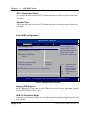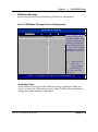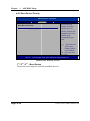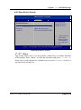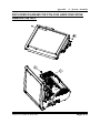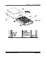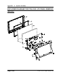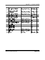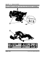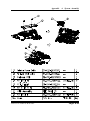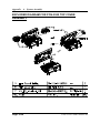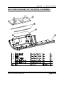
1
USER’S MANUAL POS-3520 15” POS Terminal With Intel® Atom® D525 Platform POS-3520 M2 Copyright Notice POS-3520 POS System With LCD / Touchscreen OPERATION MANUAL COPYRIGHT NOTICE This operation manual is meant to assist users in installing and setting up the system. The information contained in this document is subject to change without prior any notice. This manual is copyrighted May 2011. (Revised Edition: June 2011) You may not reproduce or transmit in any form or by any means, electronic, or mechanical, including photocopying and recording. ACKNOWLEDGEMENTS All trademarks and registered trademarks mentioned herein are the property of their respective owners. CE NOTICE This is a class A product. In a domestic environment this product may cause radio interference in which case the user may be required to take adequate measures. Copyright Notice FCC NOTICE This equipment has been tested and found to comply with the limits for a Class A digital device, pursuant to part 15 of the FCC Rules. These limits are designed to provide reasonable protection against harmful interference when the equipment is operated in a commercial environment. This equipment generates, uses, and can radiate radio frequency energy and, if not installed and used in accordance with the instruction manual, may cause harmful interference to radio communications. Operation of this equipment in a residential area is likely to cause harmful interference in which case the user will be required to correct the interference at his own expense. You are cautioned that any change or modifications to the equipment not expressly approve by the party responsible for compliance could void your authority to operate such equipment. CAUTION! Danger of explosion if battery is incorrectly replaced. Replace only with the same or equivalent type recommended by the manufacturer. Dispose of used batteries according to the manufacturer’s instructions. WARNING! Some internal parts of the system may have high electrical voltage. And therefore we strongly recommend that qualified engineers can open and disassemble the system. The LCD and Touchscreen are easily breakable, please handle them with extra care. Contents TABLE OF CONTENTS CHAPTER 1 INTRODUCTION 1-1 1-2 1-3 1-4 About This Manual ....................................................... POS Illustration ............................................................. System Specification ..................................................... Safety Precautions ......................................................... 1-2 1-3 1-4 1-6 CHAPTER 2 SYSTEM CONFIGURATION 2-1 2-2 2-3 2-4 2-5 2-6 2-7 2-8 2-9 2-10 2-11 2-12 2-13 2-14 2-15 2-16 2-17 2-18 2-19 2-20 2-21 2-22 2-23 2-24 2-25 2-26 Jumper & Connector Quick Reference Table ............... Component Locations ................................................... How to Set the Jumpers ................................................ COM Port & VGA Connector ……………………… COM Port RI and Voltage Selection ………………… Mini-DIN and USB Connector ………………………. LAN & USB Connector ……………………………… Cash Drawer Connector ……………………………… Cash Drawer Power Selection ………………………... Power LED Connector …………………………………. Smart FAN Connector ….…………………………… Power Connector ……………………………………. Reset Switch Connector …………………………….. Power for Thermal Printer Connector ………………... External Speaker Connector ………………………….. Inverter Connector …………………………………… MSR/ Card Reader Connector ……………………….. Printer Connector ……………………………………. LVDS Connector …………………………………….. SATA Connector ……………………………………... SATA Power Connector ……………………………… Touch Panel Connector ………………………………. Touch Panel Selection ………………………………. Touch Panel Interface Type Selection ……………….. Clear CMOS Data Selection ………………….…….. Compact Flash Connector …………………………… 2-2 2-3 2-4 2-6 2-9 2-13 2-14 2-15 2-16 2-17 2-17 2-17 2-18 2-18 2-18 2-19 2-20 2-20 2-21 2-23 2-23 2-24 2-24 2-25 2-26 2-27 Contents CHAPTER 3 SOFTWARE UTILITIES 3-1 3-2 3-3 3-4 3-5 3-6 3-7 Introduction …............................................................... Intel® Chipset Software Installation Utility …............. VGA Driver Utility …………………………….……. LAN Driver Utility ….................................................... Sound Driver Utility ….................................................. Touch Screen Driver Utility ………………………….. OS Support Table ……………………………………. 3-2 3-3 3-4 3-5 3-6 3-7 3-8 CHAPTER 4 AMI BIOS SETUP 4-1 4-2 4-3 4-4 4-5 4-6 4-7 4-8 Introduction …............................................................... Entering Setup …........................................................... Main …………………………….…............................. Advanced …………………………............................... Boot …………………………....................................... Security Settings ……….……....................................... Chipset ……………………..………………………... Exit ………………………............................................ 4-2 4-3 4-5 4-6 4-16 4-20 4-21 4-25 APPENDIX A SYSTEM ASSEMBLY Exploded Diagram for 2 Inch Thermal Printer Remove/ Install Exploded Diagram for 3 Inch Thermal Printer Remove/ Install Exploded Diagram for MSR & Fingerprint Module Remove/ Install …………….………………………………………… Exploded Diagram for Fingerprint Module ……………….. Exploded Diagram for POS-3520 Hard Disk Drive Remove/ Install ……………………………………………………….. Exploded Diagram for POS-3520 LCD Panel Remove/ Install .. Exploded Diagram for POS-3520 Mini-PCIE Installation .… Exploded Diagram for POS-3520 Motherboard ..…………… Exploded Diagram for POS-3520 MSR Module …….……… Exploded Diagram for POS-3520 MSR & LCD Assembly … Exploded Diagram for POS-3520 Printer Assembly ………… Exploded Diagram for POS-3520 Top Cover Assembly ........ Exploded Diagram for POS-3520 VFD Module Assembly …. A-2 A-5 A-8 A-9 A-11 A-14 A-16 A-17 A-19 A-21 A-22 A-24 A-25 Contents APPENDIX B TECHNICAL SUMMARY Block Diagram ......................................................................... Interrupt Map ............................................................................ DMA Channels Map ................................................................ I/O Map .................................................................................... Watchdog Timer Configuration ……………………………… Flash BIOS Update ………………………………………….. B-2 B-3 B-4 B-4 B-7 B-9 CHAPTER INTRODUCTION 1 This chapter gives you the information for POS-3520. It also outlines the System specifications. Section includes: About This Manual System Specifications Safety precautions Experienced users can skip to chapter 2 on page 2-1 for a Quick Start. Page:1-1 Chapter 1 Introduction 1-1. ABOUT THIS MANUAL Thank you for purchasing our POS-3520 System. The POS-3520 is an updated system designed to be comparable with the highest performance of IBM AT personal computers. The POS-3520 provides faster processing speed, greater expandability and can handle more tasks than before. This manual is designed to assist you how to install and set up the whole system. It contains four chapters. The user can apply this manual for configuration according to the following chapters: Chapter 1 Introduction This chapter introduces you to the background of this manual. It also includes illustration and the specification for the whole system. The final page of this chapter indicates some safety reminders on how to take care of your system. Chapter 2 Hardware Configuration This chapter outlines the Prox3520LF component’s location and their function. In the end of this chapter, you will learn how to set jumper and how to configure this card to meet your own needs. Chapter 3 Software Utilities This chapter contains helpful information for proper installations of the Intel Utility, VGA Utility, LAN Utility, Sound Utility, Touch Screen Utility and Flash BIOS Update. It also describes the Wireless Utility. Chapter 4 AMI BIOS Setup This chapter indicates you how to set up the BIOS configurations. Appendix A System Assembly This section gives you the exploded diagram for the whole system unit. Appendix B Technical Summary This section gives you the information about the Technical maps. Page: 1-2 POS-3520 USER′S MANUAL Chapter 1 Introduction 1-2. POS SYSTEM ILLUSTRATION Front View Rear View Side View Bottom View POS-3520 USER′S MANUAL Quarter View Page: 1-3 Chapter 1 Introduction 1-3. SYSTEM SPECIFICATIONS MAINBOARD (PROX3520LF) CPU TYPE : Intel® ATOM™ Pineview D525 CHIPSET : Intel® ICH8M MEMORY : 2 x DDR3 SO-DIMM Slot, 1G DDR3 SO-DIMM default (up to 4GB) CACHE : Depended on CPU REAL-TIME CLOCK / CALENDAR : Embedded in Intel® ICH8M South Bridge BIOS : AMI BIOS KEYBOARD CONNECTOR : PS/2 Keyboard, with mini DIN connecter on rear panel. MOUSE CONNECTOR : PS/2 Mouse, with mini DIN connecter on rear panel. SERIAL PORT : 3 x DB-9 & 1 x RJ45, +5V/ 12V selectable UNIVERSAL SERIAL BUS PORT : 5 x USB ports LAN FUNCTION : 1 x 10/100/1000 Mbps AUDIO FUNCTION : 1 x 2W Speaker Page: 1-4 POS-3520 USER′S MANUAL Chapter 1 Introduction VGA FUNCTION : 1 x DB-15 VGA interface DIMENSION (WxHxD): 356 x 309 x 167 mm (14.02" x 12.17" x 6.57") System Weight: 5.7 kg LCD PANEL: Type Max. Resolution Size/Type Viewing Angel (degree) Brightness Signal Interface (bit) SVGA 1024 x 768 15” / TFT 24~30 degrees 250 cd / m2 TTL (18-bit) TOUCH PANEL : 15” 5wire Analog resistive. PRINTER : 2” or 3” easy loading thermal printer with Auto cutter (* Diameter of paper roll can not exceed 8 cm.) I-BUTTON : (OPTIONAL) Read only, output through PS/2 KB interface MSR : (OPTIONAL) JIS-I or II, ISO Tracker 1+2+3 (PS/2 KB Interface) Wireless LAN : (OPTIONAL) Mini PCIe Wireless LAN Module (802.11b/g) FINGERPRINT : (OPTIONAL) Embedded Fingerprint module (USB interface) POS-3520 USER′S MANUAL Page: 1-5 Chapter 1 Introduction 1-4. SAFETY PRECAUTIONS Following messages are safety reminders on how to protect your systems from damages. And thus, helps you lengthen the life cycle of the system. 1. Check the Line Voltage a. The operating voltage for the power supply should cover the range of 100VAC-240VAC, otherwise the system may be damaged. 2. Environmental Conditions a. Place your POS-3520 on a sturdy, level surface. Be sure to allow enough room on each side to have easy access. b. Avoid extremely hot or cold places to install your POS-3520 POS Terminal. c. Avoid exposure to sunlight for a long period of time (for example in a closed car in summer time. Also avoid the system from any heating device.). Or do not use POS-3520 when it‘s been left outdoors in a cold winter day. d. Bear in mind that the operating ambient temperature is from 0°C up to +35°C. e. Avoid moving the system rapidly from a hot place to a cold place or vice versa because condensation may come from inside of the system. f. Place POS-3520 against strong vibrations, which may cause hard disk failure. g. Do not place the system too close to any radio active device. Radioactive device may cause interference. h. Always shutdown the operation system before turning off the power. 3. Handling a. Avoid putting heavy objects on top of the system. 4. Good Care a. When the outside of the case is stained, remove the stain with neutral washing agent with a dry cloth. b. Never use strong agents such as benzene and thinner to clean the system. c. If heavy stains are present, moisten a cloth with diluted neutral washing agent or with alcohol and then wipe thoroughly with a dry cloth. d. If dust has been accumulated on the outside, remove it by using a special made vacuum cleaner for computers. Page: 1-6 POS-3520 USER′S MANUAL SYSTEM CONFIGURATION CHAPTER 2 Helpful information that describes the jumper & connector settings, and component locations. Section includes: Jumper & Connector Quick Reference Table Component Locations Configuration and Jumper settings Connector Pin Assignments Page 2-1 Chapter 2 Hardware Configuration 2-1. JUMPER & CONNECTOR QUICK REFERENCE TABLE Connector & Jumper Name Page COM Port & VGA Connector COM1, COM3, COM4, COM2-1, JVGACOM2 2-6 COM Port RI and Voltage Selection JP_COM1, JP_COM2, JP_COM3, JP_COM4 2-9 MINI-DIN and USB Connector JPS2USB1, USB5, USB6 2-13 LAN & USB Connector JRJ45USB1 2-14 Cash Drawer Connector DRW1, DRW2 2-15 Cash Drawer Power Selection JP14, JP17 2-16 Power LED Connector LED-1 2-17 Smart Fan Connector FAN2 2-17 Power Connector FAN1 2-17 Reset Switch Connector JRST1 2-18 Power for Thermal printer Connector PRT_PWR1 2-18 External Speaker Connector SPK1 2-18 Inverter Connector INV1, INV2 2-19 MSR/ Card Reader Connector PS2 2-20 Printer Connector LPT1 2-20 LVDS Connector LVDS1, LVDS2 2-21 SATA Connector SATA1 2-23 SATA Power Connector JPWR_4P1 2-23 Touch Panel Connector TOUCH1 2-24 Touch Panel Selection JP16 2-24 Touch Panel Interface Type Selection JP15 2-25 Clear CMOS Data Selection JP1 2-26 Compact Flash Connector CF1 2-27 Page: 2-2 POS-3520 USER’S MANUAL Chapter 2 Hardware Configuration 2-2. COMPONENT LOCATIONS 20 1 1 6 5 1 1 6 5 2 1 2 1 2 1 30 29 19 1 1 1 2 1 7 8 1 2 2 3 4 2 3 1 1 1 4 1 7 204 203 204 203 74 73 72 71 74 72 73 1 3 14 26 1 13 2 1 10 9 1 3 2 4 1 71 2 1 2 1 2 1 1 4 1 4 7 1 4 3 4 6 1 10 5 1 2 7 8 2 1 1 2 5 6 14 13 12 4 9 1 5 8 9 1 10 2 2 1 1 1 2 4 3 16 21 20 6 5 2 1 6 5 3 5 1 5 1 6 5 1 5 1 24 6 2 1 6 2 1 9 6 5 2 1 9 10 1 2 4 3 2 1 COM3 PWR_IN1 POS-3520 Connector, Jumper and Component locations POS-3520 USER’S MANUAL Page: 2-3 Chapter 2 Hardware Configuration 2-3. HOW TO SET THE JUMPERS You can configure your board by setting the jumpers. Jumper is consists of two or three metal pins with a plastic base mounted on the card, and by using a small plastic "cap", Also known as the jumper cap (with a metal contact inside), you are able to connect the pins. So you can set-up your hardware configuration by "opening" or "closing" pins. The jumper can be combined into sets that called jumper blocks. When the jumpers are all in the block, you have to put them together to set up the hardware configuration. The figure below shows how this looks like. JUMPERS AND CAPS If a jumper has three pins for example, labelled PIN1, PIN2, and PIN3. You can connect PIN1 & PIN2 to create one setting and shorting. You can either connect PIN2 & PIN3 to create another setting. The same jumper diagrams are applied all through this manual. The figure below shows what the manual diagrams look and what they represent. Page: 2-4 POS-3520 USER’S MANUAL Chapter 2 Hardware Configuration JUMPER DIAGRAMS JUMPER SETTINGS POS-3520 USER’S MANUAL Page: 2-5 Chapter 2 Hardware Configuration 2-4. COM PORT & VGA CONNECTOR There are four COM ports enhanced in this board namely: COM1, COM2, COM3 and COM4. COM1: COM1 Connector The COM1 Connector assignments are as follows: PIN 1 2 3 4 5 6 7 8 9 ASSIGNMENT DCD2 RXD2 TXD2 DTR2 GND DSR2 RTS2 CTS2 RI / +5V / +12V selectable COM1 COM3: COM3 Connector The pin assignments are as follows: PIN 1 2 3 4 5 6 7 8 9 10 Page: 2-6 ASSIGNMENT DCD3 RXD3 TXD3 DTR3 GND DSR3 RTS3 CTS3 COM3 RI/+5V/+12 selectable NC POS-3520 USER’S MANUAL Chapter 2 Hardware Configuration COM4: COM4 Connector The pin assignments are as follows: PIN 1 2 3 4 5 6 7 8 9 10 ASSIGNMENT DCD4 RXD4 TXD4 DTR4 GND DSR4 RTS4 CTS4 COM4 RI NC COM2-1: COM2 External Connector The pin assignments are as follows: PIN 1 2 3 4 5 6 7 8 9 10 1 2 9 10 ASSIGNMENT DCD1 RXD1 TXD1 DTR1 GND DSR1 RTS1 CTS1 6 1 10 5 COM2_1 RI/+5V/+12 selectable NC POS-3520 USER’S MANUAL Page: 2-7 Chapter 2 Hardware Configuration JVGACOM2: COM2 & VGA Connector The COM2 & VGA Connector assignments are as follows: PIN ASSIGNMENT 1 RED 2 GREEN 3 BLUE 4 NC 5 GND 6 GND 7 GND 8 GND 9 +5V 10 GND 11 NC 12 DDCA DATA 13 HSYNC 14 VSYNC 15 DDCA CLK 16 DCD1 17 RXD1 18 TXD1 19 DTR1 20 GND 21 DSR1 22 RTS1 23 CTS1 RI/+5V/+12 selectable 24 All COM port is selectable for RI, +5V or +12V. For more information, please refer to our “COM RI and Voltage Selection”. 16 21 5 10 15 20 24 1 6 11 JVGACOM2 Page: 2-8 POS-3520 USER’S MANUAL Chapter 2 Hardware Configuration 2-5. COM PORT RI & VOLTAGE SELECTION JP_COM1: COM1 RI & Voltage Selection The selections are as follows: SELECTION JUMPER SETTINGS RI VCC12 VCC 1-2 3-4 5-6 JUMPER ILLUSTRATION 6 5 2 1 6 5 2 1 6 5 2 1 ***Manufacturing Default – RI. POS-3520 USER’S MANUAL Page: 2-9 Chapter 2 Hardware Configuration JP_COM2: COM2 RI & Voltage Selection The selections are as follows: SELECTION RI VCC12 VCC JUMPER SETTINGS 1-2 3-4 5-6 JUMPER ILLUSTRATION 5 6 1 2 5 6 1 2 5 6 1 2 ***Manufacturing Default – RI. Page: 2-10 POS-3520 USER’S MANUAL Chapter 2 Hardware Configuration JP_COM3: COM3 RI & Voltage Selection The selections are as follows: SELECTION JUMPER SETTINGS RI VCC12 VCC 1-2 3-4 5-6 JUMPER ILLUSTRATION 6 5 2 1 6 5 2 1 6 5 2 1 ***Manufacturing Default – RI. POS-3520 USER’S MANUAL Page: 2-11 Chapter 2 Hardware Configuration JP_COM4: COM4 RI & Voltage Selection The selections are as follows: SELECTION RI VCC12 VCC JUMPER SETTINGS 1-2 3-4 5-6 JUMPER ILLUSTRATION 5 6 1 2 5 6 1 2 5 6 1 2 ***Manufacturing Default – RI. Page: 2-12 POS-3520 USER’S MANUAL Chapter 2 Hardware Configuration 2-6. MINI-DIN AND USB CONNECTOR JPS2USB1: Two USB Ports Connector and MINI-DIM MINI-DIN connector can support keyboard, Y-cable, or PS/2 Mouse The pin assignment is as follows: PIN 1 2 3 4 5 6 7 8 9 10 11 12 13 14 ASSIGNMENT GND USB2+ USB2VCC5 GND USB3+ USB3VCC5 GND KDAT MDAT V5SB KCLK MCLK 9 11 10 JPS2USB1 USB5: Internal USB Ports Connector The pin assignment is as follows: PIN 1 2 3 4 5 ASSIGNMENT USB5USB5+ GND VCC5 GND POS-3520 USER’S MANUAL 5 1 Page: 2-13 Chapter 2 Hardware Configuration USB6: Internal USB Ports Connector The pin assignment is as follows: PIN 1 2 3 4 5 ASSIGNMENT USB6USB6+ GND VCC5 GND 1 5 2-7. LAN & USB CONNECTOR JRJ45USB1: LAN & USB Connector The pin assignments are as follows: PIN 1 2 3 4 5 6 7 8 ASSIGNMENT LAN1_MDIP0 LAN1_MDIN0 LAN1_MDIP1 LAN1_MDIN1 LAN1_MDIP2 LAN1_MDIN2 LAN1_MDIP3 LAN1_MDIN3 PIN A1 A2 A3 A4 B1 B2 B3 B4 ASSIGNMENT VCC5 USB0USB0+ GND VCC5 USB1USB1+ GND Page: 2-14 Orange Green B4 B1 A4 A1 JRJ45USB1 POS-3520 USER’S MANUAL Chapter 2 Hardware Configuration 2-8. CASH DRAWER CONNECTOR DRW1, DRW2: Cash Drawer Connector The pin assignment is as follows: PIN 1 2 3 4 5 6 ASSIGNMENT GND Drawer Open Drawer Sense +12V NC GND 6 1 DRW1 PROX-A3520 cash drawer control in GPIO port To Open Drawer1 (GPIO 7) Write "00"h to I/O Port "50C"h Bit 7 To Close Drawer1 Write "01"h to I/O Port "50C"h Bit 7 Detect Drawer1 Status Read I/O "50E"h (GPIO 20) Definition (bit4) 6 1 DRW2 To Open Drawer2 (GPIO 6) Write "00"h to I/O Port "50C"h Bit 6 To Close Drawer2 Write "01"h to I/O Port "50C"h Bit 6 Detect Drawer2 Status Read I/O "538"h (GPIO 37) Definition (bit5) POS-3520 USER’S MANUAL Page: 2-15 Chapter 2 Hardware Configuration 2-9. CASH DRAWER POWER SELECTION JP14, JP17: Cash Drawer Power Selection The jumper settings are as follows: SELECTIO N JUMPER SETTINGS JUMPER ILLUSTRATION 1 +12V 2-3 3 1 3 1 +24V (default) 1-2 3 1 3 *** Manufactory default --- +24V. Page: 2-16 POS-3520 USER’S MANUAL Chapter 2 Hardware Configuration 2-10. POWER LED CONNECTOR LED-1: LED Connector The pin assignment is as follows: PIN 1 2 1 ASSIGNMENT GND VCC_PWR_LED 2-11. SMART FAN CONNECTOR FAN2: CPU Smart Fan Connector. The pin assignments are as follows: PIN ASSIGNMENT 1 GND 2 12V 3 CPUFANIN 4 CPUFANOUT 4 1 2-12. POWER CONNECTOR FAN1: Provide 12 Voltage Connector The pin assignment is as follows: PIN 1 2 1 2 ASSIGNMENT VCC12 GND POS-3520 USER’S MANUAL Page: 2-17 Chapter 2 Hardware Configuration 2-13. RESET SWITCH CONNECTOR 1 RST_SW1: Power Switch Connector The pin assignment is as follows: PIN 1 2 ASSIGNMENT RST_SW GND 2-14. POWER FOR THERMAL PRINTER CONNECTOR PRT_PWR1: Power for Thermal printer Connector The pin assignment is as follows: PIN 1 2 3 4 1 4 ASSIGNMENT VCC24SB VCC24SB GND GND 2-15. EXTERNAL SPEAKER CONNECTOR SPK1: External Speaker Connector The pin assignment is as follows: PIN 1 2 Page: 2-18 1 ASSIGNMENT SPK_GND SPK_OUT POS-3520 USER’S MANUAL Chapter 2 Hardware Configuration 2-16. INVERTER CONNECTOR INV1: Inverter Connector The pin assignment is as follows: PIN 1 2 3 4 5 6 7 1 7 ASSIGNMENT +12V +12V GND GND LVDS_BKLTEN BRCTR GND INV2: Inverter Connector The pin assignment is as follows: PIN 1 2 3 4 ASSIGNMENT +12V GND LVDS_BKLTEN BRCTR POS-3520 USER’S MANUAL 4 1 Page: 2-19 Chapter 2 Hardware Configuration 2-17. MSR/ CARD READER CONNECTOR PS2: MSR/ Card Reader Connector The pin assignment is as follows: PIN 1 2 3 4 5 6 1 6 ASSIGNMENT KB_CLK (Output) KB_CLK_C (Input) KB_DATA_C (Input) KB_DATA (Output) +5V GND 2-18. PRINTER CONNECTOR LPT1: LPT Connector. 14 1 The assignments are as follows: PIN ASSIGNMENT PIN 1 STBJ 14 2 PDR0 15 3 PDR1 16 4 PDR2 17 5 PDR3 18 6 PDR4 19 7 PDR5 20 8 PDR6 21 9 PDR7 22 10 ACKJ 23 11 BUSY 24 12 PE 25 13 SLCTJ 26 Page: 2-20 26 13 ASSIGNMENT ALFJ ERRJ PAR_INITJ SLCTINJ GND GND GND GND GND GND GND GND NC POS-3520 USER’S MANUAL Chapter 2 Hardware Configuration 2-19. LVDS Connector LVDS1: LVDS Connector 20 2 19 1 The pin assignments are as follows: PIN 1 3 5 7 9 11 13 15 17 19 ASSIGNMENT GND LVDS_YAP2 LVDS_YAM2 GND LVDS_YAP1 LVDS_YAM1 GND LVDS_YAP0 LVDS_YAM0 GND POS-3520 USER’S MANUAL PIN 2 4 6 8 10 12 14 16 18 20 ASSIGNMENT LVDS_VCC LVDS_VCC GND GND LVDS_CLKAP LVDS_CLKAM GND GND LVDS_VCC LVDS_VCC Page: 2-21 Chapter 2 Hardware Configuration LVDS2: LVDS Connector. 30 29 2 1 The pin assignments are as follows: PIN ASSIGNMENT PIN ASSIGNMENT 1 LVDS_VCC 2 GND 3 NC 4 NC 5 GND 6 NC 7 NC 8 GND 9 NC 10 NC 11 NC 12 NC 13 NC 14 NC 15 GND 16 CLKO+ 17 CLKO18 GND 19 RINO2+ 20 RINO221 GND 22 RINO1+ 23 RINO124 GND 25 RINO0+ 26 RINO027 NC 28 NC 29 LVDS_VCC 30 LVDS_VCC Page: 2-22 POS-3520 USER’S MANUAL Chapter 2 Hardware Configuration 2-20. SATA CONNECTOR SATA1: Serial ATA Connector The pin assignments are as follows: PIN 1 2 3 4 5 6 7 7 1 4 1 ASSIGNMENT G1 TX+ TXG2 RXRX+ G3 2-21. SATA POWER CONNECTOR JPWR_4P1: Serial ATA Connector The pin assignments are as follows: PIN 1 2 3 4 ASSIGNMENT VCC GND GND VCC12 POS-3520 USER’S MANUAL Page: 2-23 Chapter 2 Hardware Configuration 2-22. TOUCH PANEL CONNECTOR TOUCH1: Touch Panel Connector The pin assignments are as follows: PIN 1 2 3 4 5 1 ASSIGNMENT LR (Low Right) LL (Low Left) Probe UR (Up Right) UL (Up Left) 2-23. TOUCH PANEL SELECTION JP16: Touch Panel Selection. The selections are as follows: SELECTION e-Turbo Elo JUMPER SETTINGS 1-2 & 5-6 3-4 & 7-8 JUMPER ILLUSTRATION 7 8 1 2 7 8 1 2 *** Manufactory default --- Elo. Page: 2-24 POS-3520 USER’S MANUAL Chapter 2 Hardware Configuration 2-24. TOUCH PANEL INTERFACE TYPE SELECTION JP15: Touch Panel Type Selection The selections are as follows: SELECTION JUMPER SETTINGS USB 1-2 JUMPER ILLUSTRATION 4 2 3 1 4 2 3 1 3-4 RS-232 NC *** Manufactory default --- USB. POS-3520 USER’S MANUAL Page: 2-25 Chapter 2 Hardware Configuration 2-25. CLEAR CMOS DATA SELECTION JP1: Clear CMOS Data Selection The selections are as follows: FUNCTION JUMPER SETTING JUMPER ILLUSTRATION (pin closed) 1 CLEAR CMOS 2-3 3 1 NORMAL 1-2 3 *** Manufacturing Default – Normal. To clear CMOS data, user must power-off the computer and set the jumper to “Clear CMOS” as illustrated above. After five to six seconds, set the jumper back to “Normal” and power-on the computer. Page: 2-26 POS-3520 USER’S MANUAL Chapter 2 Hardware Configuration 2-26. Compact Flash Connector CF1: Compact Flash Connector. The pin assignments are as follows: PIN 1 2 3 4 5 6 7 8 9 10 11 12 13 14 15 16 17 18 19 20 21 22 23 24 25 ASSIGNMENT GND D03 D04 D05 D06 D07 CSJ1 GND GND GND GND GND +5V GND GND GND GND A02 A01 A00 D00 D01 D02 NC GND POS-3520 USER’S MANUAL PIN 26 27 28 29 30 31 32 33 34 35 36 37 38 39 40 41 42 43 44 45 46 47 48 49 50 ASSIGNMENT GND D11 D12 D13 D14 D15 CSJ3 GND SDIORDJ SDIOWRJ +5V IRQ14 +5V -CSEL NC RESETJ IORDJ REQ ACKJ CF_LEDJ -PDIAG D08 D09 D10 GND Page: 2-27 SOFTWARE UTILITIES CHAPTER 3 This chapter comprises the detailed information of VGA driver, LAN driver, and Sound driver. It also describes the OS support table. Section includes: Intel® Chipset Software Installation Utility VGA Driver Utility LAN Driver Utility Sound Driver Utility Touch Screen Driver Utility OS Support Table Page: 3-1 Chapter 3 Software Configuration 3-1. INTRODUCTION Enclosed with our POS-3520 package is our driver utility, which may comes in a form of a CD ROM disc or floppy diskettes. For CD ROM disc user, you will only need some of the files contained in the CD ROM disc, please kindly refer to the following chart: Filename (Assume that CD ROM drive is D:) D:\Driver\UTILITY Purpose Intel® Chipset Software Installation Utility D:\Driver\VGA Intel® Graphics Media Accelerator 3150 For VGA driver installation D:\Driver\LAN Realtek 8111DL For LAN Driver installation D:\Driver\Sound Realtek ALC888 For Sound driver installation D:\Driver\TOUCH Elo Touch driver installation User should remember to install the Utility right after the OS is fully installed. Page:3-2 POS-3520 USERS MANUAL Chapter 3 Software Configuration 3-2. INTEL® CHIPSET SOFTWARE INSTALLATION UTILITY 3-2-1. Introduction The Intel® Chipset Software Installation Utility installs to the target system the Windows* INF files that outline to the operating system how the chipset components will be configured. This is needed for the proper functioning of the following features: - Core PCI and ISAPNP Services AGP Support SATA Storage Support USB Support Identification of Intel® Chipset Components in Device Manager 3-2-2. Installation of Utility for Windows XP, Windows 7 32Bit, Windows 64Bit, POSReady2009 The Utility Pack is to be installed only for Windows XP, Windows 7 32bit, Windows 7 64bit, POSReady 2009 program. It should be installed right after the OS installation, kindly follow the following steps: 1. 2. 3. 4. Please insert the Utility Disk into Floppy Disk Drive A/B or CD ROM drive. Under Windows XP, Windows 7 32bit, Windows 7 64bit, POSReady 2009 system, go to the directory where Utility Disc is located. Click Setup.exe file for utility installation. Follow the instructions on the screen to complete the installation. Once installation is completed, shut down the system and restart it in order to complete the changes. POS-3520 USERS MANUAL Page:3-3 Chapter 3 Software Configuration 3-3. VGA DRIVER UTILITY The VGA interface embedded with our POS-3520 can support a wide range of display. You can display CRT, LVDS simultaneously with the same mode. 1. Win XP program 2. POSReady 2009 3. Win 7 32bit program 4. Win 7 64bit program 3-3-1. Installation of VGA Driver: To install the VGA Driver, simply follow the following steps: 1. 2. 3. 4. 5. Page:3-4 Please insert the Utility Disk into Floppy Disk Drive A/B or CD ROM drive. Under Windows XP, Windows 7 32bit, Windows 7 64bit, POSReady 2009 system, go to the directory where VGA driver is located. Click Setup.exe file for VGA driver installation. Follow the instructions on the screen to complete the installation. Once installation is completed, shut down the system and restart it in order to complete the changes. POS-3520 USERS MANUAL Chapter 3 Software Configuration 3-4. LAN DRIVER UTILITY 3-4-1. Introduction POS-3520 is enhanced with LAN function that can support various network adapters. Installation programs for LAN driver is listed as follows: 1. Win XP program 2. POSReady 2009 3. Win 7 32bit program 4. Win 7 64bit program For more details on Installation procedure, please refer to Readme.txt file found on LAN DRIVER UTILITY. POS-3520 USERS MANUAL Page:3-5 Chapter 3 Software Configuration 3-5. SOUND DRIVER UTILITY 3-5-1. Introduction The sound function enhanced in this system is fully compatible with Windows XP, Windows 7 32bit, Windows 7 64bit and POSReady 2009. Below, you will find the content of the Sound driver : 1. Win XP program 2. POSReady 2009 3. Win 7 32bit program 4. Win 7 64bit program 3-5-2. Installation Procedure To install, kindly refer to the readme.txt file on the Driver Disc (:\Sound\Realtek\Readme.txt). Page:3-6 POS-3520 USERS MANUAL Chapter 3 Software Configuration 3-6. TOUCHSCREEN DRIVER UTILITY The touchscreen driver utility is to be installed only for Windows XP, Windows 7 32bit, Windows 7 64bit, POSReady 2009 program. 1. Win XP program 2. POSReady 2009 3. Win 7 32bit program 4. Win 7 64bit program It should be installed right after the OS installation, kindly follow the following steps: 1. 2. 3. 4. 5. Please insert the Utility Disk into Floppy Disk Drive A/B or CD ROM drive. Under Windows XP, Windows 7 32bit, Windows 7 64bit, POSReady 2009 system, go to the directory where Utility Disc is located. Click Setup.exe file for utility installation. Follow the instructions on the screen to complete the installation. Once installation is completed, shut down the system and restart it in order to complete the changes. POS-3520 USERS MANUAL Page:3-7 Chapter 3 Software Configuration 3-7 OS SUPPORT TABLE Operating System Windows XP Professional WEPOS POS Ready 2009 Windows 7 32bit Windows 7 64bit Fedora Core Ubuntu Page:3-8 Version SP3 1.0 1.0 Ultimate Ultimate 14 11.04 Language English English English English English English English Company Microsoft Microsoft Microsoft Microsoft Microsoft Linux Linux POS-3520 USERS MANUAL CHAPTER AMI BIOS SETUP 4 This chapter shows how to setup the AMI BIOS. Section includes: Introduction Entering Setup Main Advanced Boot Security Chipset Exit Page: 4-1 Chapter 4 AMI BIOS Setup 4-1. INTRODUCTION This chapter will show you the function of the BIOS (Basic Input and Output System) in managing the features of your system. The POS-3520 POS Terminal is equipped with the BIOS from AMI (American Megatrends Inc). The following pages describe how to use the BIOS for configure system hardware by BIOS Setup menu. When the PC starts up, the first job for the BIOS is to initialize and identify system devices such as the video display card, keyboard and mouse, hard disk, CD/DVD drive and other hardware. The BIOS then locates software held on a peripheral device (designated as a 'boot device'), such as a hard disk or a CD, and loads and executes that software, giving it control of the PC. BIOS code is stored on a non-volatile, ROM chip built into the system, on the mother board and the BIOS software is specifically designed to work with the particular type of system in question including having a knowledge of the workings of various devices that make up the complementary chipset of the system BIOS also provide a user interface, this is a menu system accessed by pressing a certain key on the keyboard when the PC starts. In the BIOS UI, a user can configure hardware, set the system clock, enable or disable system components, and most importantly, select which devices are eligible to be a potential boot device and set various password prompts, most importantly a password for securing access to the BIOS UI functions itself and preventing malicious users from booting the system from unauthorized peripheral devices. The following diagram illustrates the relationships between system hardware, BIOS, operating system, and application program: Page: 4-2 POS-3520 USERS MANUAL Chapter 4 AMI BIOS Setup 4-2 ENTERING SETUP When system powered on, BIOS will enter the Power-On Self Test (POST) routines and displays below message on the screen: American www.ami.com Megatrends AMI BIOS (C) 2009 American Megatrends, Inc. BIOS Date: 04/28/11 12:30:29 Ver: 08.00.16 Board BIOS Version: 35200T04 CPU : Intel (R) Atom(TM) CPU D525 @ 1.80GHz Speed : 1.80 GHz Press DEL to run Setup Initializing USB Controllers .. Done. 1014MB OK (C) American Megatrends, Inc. 64-0100-009999-00101111-042811-Pineview-35200T04-Y2KC 423C POST Screen As long as this logo is present on the screen you may press the <Del> key (the one that shares the decimal point at the bottom of the number keypad) to enter the BIOS setup program. In a moment, the main menu of the AMI SETUP program will be shown on the screen: POS-3520 USERS MANUAL Page: 4-3 Chapter 4 AMI BIOS Setup BIOS SETUP UTILITY Main Advanced Boot Security Chipset ExitM Use [ENTER], [TAB] or [SHIFT-TAB] to select a field. System Overview AMIBIOS Version Build Date Use [+] or [-] to configure system Time. :35200T04 : 04/28/11 Processor Intel(R) Atom(TM) CPU D525 Speed :1800MHz Count :1 System Memory Size System Time System Date v02.68 @1.80GHz : 1014MB [01:57:52] [Wed 04/29/2011] Select Screen Select Item +Change Field Tab Select Field F1 General Help F10 Save and Exit ESC: Exit (c)Copyright 1985-2009 American Megatrends, Inc. Setup program initial screen You may move the cursor by up/down keys to highlight the individual menu items. As you highlight each item, a brief description of the highlighted selection will appear at the bottom of the screen. Page: 4-4 POS-3520 USERS MANUAL Chapter 4 AMI BIOS Setup 4-3. Main BIOS SETUP UTILITY Main Advanced Boot Security Chipset ExitM Use [ENTER], [TAB] or [SHIFT-TAB] to select a field. System Overview AMIBIOS Version Build Date Use [+] or [-] to configure system Time. :35200T04 : 04/28/11 Processor Intel(R) Atom(TM) CPU D525 Speed :1800MHz Count :1 System Memory Size : 1014MB System Time System Date v02.68 @1.80GHz [01:57:52] [Wed 04/29/2011] Select Screen Select Item +Change Field Tab Select Field F1 General Help F10 Save and Exit ESC: Exit (c)Copyright 1985-2009 American Megatrends, Inc. Main Screen use <↑> or <↓> arrow keys to highlight the item and key in the value you want in each item. This menu provides basic system configurations, such as time and date. AMI BIOS, Processor, System Memory This items show the BIOS version, BIOS build up date, processor and system memory information of your system. System Time This setting allows you to set the system time. The format is [Hour: Minute: Second]. User can directly key-in value or use <+> or <-> arrow keys to increase/decrease it. POS-3520 USERS MANUAL Page: 4-5 Chapter 4 AMI BIOS Setup System Date This setting allows you to set the system date. The format is [Day Month/ Date/ Year]. User can directly key-in value or use <+> or <-> arrow keys to increase/decrease it. 4-4. Advanced BIOS SETUP UTILITY Main Advanced Boot Security Chipset ExitM Configure CPU. Advanced Settings WARNING: Setting wrong values in below sections May cause system to malfunction. CPU Configuration IDE Configuration SuperIO Configuration Hardware Health Configuration APM Configuration USB Configuration v02.68 Select Screen Select Item Enter Go to Sub Screen F1 General Help F10 Save and Exit ESC Exit (c)Copyright 1985-2009 American Megatrends, Inc. Advanced Screen This menu provides advanced configurations such as CPU Configuration, IDE Configuration, SuperIO Configuration…etc. Page: 4-6 POS-3520 USERS MANUAL Chapter 4 AMI BIOS Setup 4-4.1. CPU Configuration BIOS SETUP UTILITY Main Advanced PCIPnP Boot Security Chipset Configure advanced CPU settings Module Version: 3F. 1C Manufacturer: Intel Intel(R) Atom(TM) CPU D525 Frequency : 1.80GHz FSB Speed : 800MHz Cache L1 : 48 KB Cache L2 : 1024 KB Ratio Actual Value : 9 Hyper Threading Technology @ 1.80GHz ExitM Enabled for Windows XP and Linux4 (OS optimized for Hyper Threading Technology) and disabled for other OS (OS not optimized for Hyper-Threading Technology) [Enabled] Select Screen Select Item +Change Option F1 General Help F10 Save and Exit ESC: Exit v02.68 (c)Copyright 1985-2009 American Megatrends, Inc. CPU Configuration Screen This menu provides some information about CPU. Hyper Threading Technology Hyper Threading is Intel’s term for its simultaneous multithreading implementation in their CPUs. Enable this function will improve parallelization of computation performed on PC microprocessor. For each processor core that is physically present, the operation system addresses two virtual processors, and shares the workload between them when possible. POS-3520 USERS MANUAL Page: 4-7 Chapter 4 AMI BIOS Setup 4-4.2. IDE Configuration BIOS SETUP UTILITY Main Advanced PCIPnP Boot IDE Configuration SATA1 CF Card Security Chipset ExitM While entering setup, BIOS auto detects the presence of IDE devices. This displays the status : [FUJITSU MHY20] of auto detection of IDE : [Transcend] devices. Select Screen Select Item +Change Option F1 General Help F10 Save and Exit ESC: Exit v02.68 (c)Copyright 1985-2009 American Megatrends, Inc. IDE Configuration Screen This menu provides advanced IDE configuration for hard drive. The control items of SATA 1 / CF Card are all the same and describe in next section. SATA 1/ CF Card This setting displays the status of storages. Page: 4-8 POS-3520 USERS MANUAL Chapter 4 AMI BIOS Setup 4-4.2.1 SATA 1 and CF Card BIOS SETUP UTILITY Main Advanced PCIPnP Boot Security Chipset ExitM Select the type of device connected to the system. SATA 1 Device Vendor Size LBA Mode Block Mode PIO Mode Async DMA Ultra DMA S.M.A.R.T. : Hard Disk : FUJUTSU MHY2040BH ESW : 40.0GB : Supported : 16 Sectors :4 : MultiWord DMA-2 : Ultra DMA-5 : Supported Type LBA/Large Mode Block (Multi-Sector Transfer) PIO Mode DMA Mode S.M.A.R.T. 32Bit Data Transfer [Auto] [Auto] [Auto] [Auto] [Auto] [Auto] [Enabled] Select Screen Select Item +- Change Option F1 General Help F10 Save and Exit ESC: Exit v02.68 (c)Copyright 1985-2009 American Megatrends, Inc. SATA 1 Screen Type Select the type of device connected to the system. LBA/Large Mode Enabling LBA causes Logical Block Addressing to be used in place of Cylinders, Heads and Sectors. POS-3520 USER′S MANUAL Page: 4-9 Chapter 4 AMI BIOS Setup Block (Multi-Sector Transfer) Any selection except Disabled determines the number of sectors transferred per block. PIO Mode Configure the type of PIO (Programmed Input/Output) mode 0-4 for IDE device. Mode 0 through 4 provides successively increased performance. DMA Mode Select the type of Ultra DMA mode on a hard drive. S.M.A.R.T This allows you to activate the S.M.A.R.T. (Self-Monitoring Analysis & Reporting Technology) capability for the hard disks. S.M.A.R.T is a utility that monitors your disk status to predict hard disk failure. This gives you an opportunity to move data from a hard disk that is going to fail to a safe place before the hard disk becomes offline. 32Bit Data Transfer Enables/Disable 32-bit data transfer. Page: 4-10 POS-3520 USER′S MANUAL Chapter 4 AMI BIOS Setup 4-4.3. SuperIO Configuration BIOS SETUP UTILITY Main Advanced PCIPnP Boot Security Chipset Configure Win627UHG Super IO Chipset Watchdog Function Serial Port1 Address Serial Port1 IRQ Serial Port2 Address Serial Port2 IRQ Serial Port3 Address Serial Port3 IRQ Serial Port4 Address Serial Port4 IRQ Parallel Port Address Parallel Port Mode Parallel Port IRQ [Disabled] [2F8] [IRQ3] [3F8] [IRQ4] [3E8] [IRQ11] [2E8] [IRQ10] [378] [Normal] [IRQ7] ExitM Allows BIOS to Select WDTO function. Select Screen Select Item +Change Option F1 General Help F10 Save and Exit ESC: Exit v02.68 (c)Copyright 1985-2009 American Megatrends, Inc. SuperIO Configuration Screen * WatchDog function If system hang or not respond for user, enable watchdog function can triggers a system reset by an user given value count down to zero. Serial Port1~4 Address Select IO address as serial ports default resource. Serial Port1~4 IRQ Select IO IRQ as serial ports default resource. Parallel Port Address Select IO address for parallel ports resource allocation. Parallel Port Mode Select the operation mode for parallel port. POS-3520 USER′S MANUAL Page: 4-11 Chapter 4 AMI BIOS Setup Parallel Port IRQ Select IRQ for parallel ports resource allocation. 4-4.4. Hardware Health Configuration BIOS SETUP UTILITY Main Advanced PCIPnP Boot Security Chipset ExitM Fan configuration mode setting Hardware Health Configuration ℃ ℉ ℃ ℉ SYS Temperature CPU Temperature : 35 /95 :33 /91 CPUFAN Speed : 6026 RPM Vcore 12V 5V 1.05V VSB : 1.024 V : 11.776 V : 5.088 V : 1.0249 V : 5.140 V +F1 F10 ESC Select Screen Select Item Change Option General Help Save and Exit Exit v02.68 (c)Copyright 1985-2009 American Megatrends, Inc. Hardware Health Configuration System Temperature / CPU Temperature Both section show System and CPU current temperature. CPUFAN Speed This item shows CPU fan speed. VCORE / 12V / 5V / 1.05V /VSB These items provide hardware health information. Page: 4-12 POS-3520 USER′S MANUAL Chapter 4 AMI BIOS Setup 4-4.5. APM Configuration BIOS SETUP UTILITY Main Advanced PCIPnP Boot Security Chipset ExitM Go into On/Off, or Delay 4 sec when Power button is pressed. APM Configuration Power Button Mode Restore on AC Power Loss [On/Off] [Last State] Resume On RTC Alarm [Disabled] Select Screen Select Item +Change Option F1 General Help F10 Save and Exit ESC: Exit v02.68 (c)Copyright 1985-2009 American Megatrends, Inc. APM Configuration Screen Power Management/APM This is the main control item for enable/disable below APM functions. Power Button Mode This setting controls shutdown action by pressing power button. The system will be shutdown immediately after pressing power button when set to “On/Off”. If set the power button mode to “Delay 4 seconds”, system will be shutdown after pressing and hold the power button over 4 seconds. Restore on AC/Power Loss Once a power failure situation happens, this item decides the system power state after AC power restore back. Resume On RTC Alarm When user set this option to [Enable], it allows system to be wake up at specific date/time. POS-3520 USERS MANUAL Page: 4-13 Chapter 4 AMI BIOS Setup RTC Alarm Date (Days) Set a specific date value for RTC alarm function to wakeup system from soft off state. System Time Set a specific time value for RTC alarm function to wakeup system from soft off state. 4-4.6.USB Configuration BIOS SETUP UTILITY Main Advanced PCIPnP Boot Security Chipset Enables support for legacy USB. AUTO option disables legacy support if no USB devices are connected. USB Configuration Module Version – 2.24.5-14.4 USB Devices Enabled: 1 Drive Legacy USB Support USB2.0 Controller Mode USB Beep Message [Enabled] [HiSpeed] [Enabled] +F1 F10 ESC USB Mass Storage Device Configuration v02.68 ExitM Select Screen Select Item Change Option General Help Save and Exit Exit (c)Copyright 1985-2009 American Megatrends, Inc. USB Configuration Screen Legacy USB Support Set to [Enabled] if you want to use USB device in the legacy operating system, such as MS-DOS or SCO Unix. USB 2.0 Controller Mode Configure the onboard USB 2.0 controller operation mode to high Speed or full speed mode. Page: 4-14 POS-3520 USERS MANUAL Chapter 4 AMI BIOS Setup USB Beep Message System will generate beep sound during USB device enumeration. 4-4.6.1 USB Mass Storage Device Configuration BIOS SETUP UTILITY Main Advanced PCIPnP Boot Security Chipset USB Mass Storage Device Configuration Device #1 Emulation Type USB2.0 USB Flash Disk [Auto] ExitM If Auto, USB devices less than 530MB will be emulated as Floppy and remaining as hard drive. Forced FDD option can be used to force a HDD formatted drive to boot as FDD. (Ex. ZIP drive). Select Screen Select Item +Change Option F1 General Help F10 Save and Exit ESC: Exit v02.68 (c)Copyright 1985-2009, American Megatrends, Inc. Emulation Type Select which type of device that USB mass storage emulation. When user select to [Auto], the USB storage size less than 530MB will be emulated as floppy drive and remaining as hard drive. POS-3520 USERS MANUAL Page: 4-15 Chapter 4 AMI BIOS Setup 4-5. Boot BIOS SETUP UTILITY Main Advanced Boot Security Chipset ExitM Configure Settings during System Boot. Boot Settings Boot Settings Configuration Boot Device Priority Hard Disk Drives PXE Support [Disabled] Select Screen Select Item Enter Go to Sub Screen F1 General Help F10 Save and Exit ESC: Exit v02.68 (c)Copyright 1985-2009 American Megatrends, Inc. Boot Screen This menu provides control items for system boot configuration. PXE Support This is the main control item for enable/disable PXE (Preboot Execution Environment) support. Page: 4-16 POS-3520 USERS MANUAL Chapter 4 AMI BIOS Setup 4-5.1 Boot Settings Configuration BIOS SETUP UTILITY Main Advanced PCIPnP Boot Security Chipset Boot Settings Configuration Quick Boot Quiet Boot Parity Check [Enabled] [Disabled] [Disabled] ExitM Allows BIOS to skip certain tests while booting. This will decrease the time needed to boot the system. Select Screen Select Item +Change Option F1 General Help F10 Save and Exit ESC: Exit v02.68 (c)Copyright 1985-2009 American Megatrends, Inc. Boot Settings Configuration Screen Quick Boot Enable this item allows BIOS POST to skip some tests during boot-up for saving boot time. Quiet Boot When set this option to [disabled], BIOS will display normal POST messages. Parity Check This setting enables or disables memory or parity error check. POS-3520 USERS MANUAL Page: 4-17 Chapter 4 AMI BIOS Setup 4-5.2 Boot Device Priority BIOS SETUP UTILITY Main Advanced PCIPnP Boot Security Chipset Boot Device Priority 1st Boot Device [USB: USB2.0 USB Fla] ExitM Specify the boot sequence from the available devices. A device enclosed in parenthesis has been disabled in the corresponding type menu. Select Screen Select Item +Change Option F1 General Help F10 Save and Exit ESC: Exit v02.68 (c)Copyright 1985-2009 American Megatrends, Inc. Boot Device Priority Screen 1st / 2nd / 3rd …Boot Device Choose the boot sequence from the available devices.. Page: 4-18 POS-3520 USERS MANUAL Chapter 4 AMI BIOS Setup 4-5.3 Boot Device Priority BIOS SETUP UTILITY Main Advanced PCIPnP Boot Security Chipset Hard Disk Drives 1st Drive 2nd Drive 3rd Drive [USB:Ut165 USB2Flas] [HDD:3M-Transcend] [SATA: PM-FUJITSU MH] ExitM Specify the boot sequence from the available devices. Select Screen Select Item +Change Option F1 General Help F10 Save and Exit ESC: Exit v02.68 (c)Copyright 1985-2009 American Megatrends, Inc. Hard Disk Drives Screen 1st / 2nd …Drive This setting allows user to set the priority of hard drive or another bootable USB storages. Press <Enter> to enter the sub-menu and press <↑> or <↓> arrow keys to select the device. Another way is to press <+> or <-> to move it up/down in the priority list. POS-3520 USERS MANUAL Page: 4-19 Chapter 4 AMI BIOS Setup 4-6. Security Settings BIOS SETUP UTILITY Main Advanced Boot Security Chipset ExitM Install or Change the password. Security Settings Supervisor Password : Not Installed User Password : Not Installed Change Supervisor Password Change User Password Clear User Password Enter F1 F10 ESC v02.68 Select Screen Select Item Change General Help Save and Exit Exit (c)Copyright 1985-2009 American Megatrends, Inc. Security Settings Screen Change Supervisor Password Supervisor Password controls the access right to the BIOS Setup utility. These settings allow user to set or change the supervisor password. Change User Password User Password controls system access right when power on. These settings allow user to set or change the user password. Page: 4-20 POS-3520 USERS MANUAL Chapter 4 AMI BIOS Setup 4.7 Chipset BIOS SETUP UTILITY Main Advanced Boot Security Chipset Exit Advanced Chipset Settings Configure North Bridge features. WARNING: Setting wrong values in below sections may cause system to malfunction. North Bridge Configuration South Bridge Configuration Select Screen Select Item Enter Go to Sub Screen F1 General Help F10 Save and Exit ESC: Exit v02.68 (c)Copyright 1985-2009 American Megatrends, Inc. Advanced Chipset Settings Screen POS-3520 USERS MANUAL Page: 4-21 Chapter 4 AMI BIOS Setup 4-7.1 North Bridge Chipset Configuration BIOS SETUP UTILITY Main Advanced PCIPnP Boot Security Chipset ExitM North Bridge Chipset Configuration Video Function Configuration +F1 F10 ESC v02.68 Select Screen Select Item Change Option General Help Save and Exit Exit (c)Copyright 1985-2009 American Megatrends, Inc. North Bridge Chipset Configuration Page: 4-22 POS-3520 USERS MANUAL Chapter 4 AMI BIOS Setup 4-7.1.1 Video Function Configuration BIOS SETUP UTILITY Main Advanced PCIPnP Boot Security Chipset ExitM Options Video Function Configuration DVMT Mode Select DVMT/FIXED Memory [DVMT Mode] [256MB] Boot Display Device Flat Panel Type [CRT+LVDS] [1024x768] Fixed Mode DVMT Mode Select Screen Select Item +Change Options F1 General Help F10 Save and Exit ESC: Exit v02.68 (c)Copyright 1985-2009 American Megatrends, Inc. Video Function Configuration Screen DVMT Mode Select / DVMT/FIXED Memory Intel’s Dynamic Video Memory Technology (DVMT) allows the system to dynamically allocated memory resources according to the demands of the system at any point in time. The key idea in DVMT is to improve the efficiency of the memory allocated to either system or graphics processor. It is recommended that you set this BIOS feature to DVMT Mode for maximum performance. Setting it to DVMT Mode ensures that system memory is dynamically allocated for optimal balance between graphics and system performance. Boot Display Device Choose the default boot display device by user requirement such as [CRT], [LVDS] and [CRT+LVDS] POS-3520 USERS MANUAL Page: 4-23 Chapter 4 AMI BIOS Setup Flat Panel Type Select the resolution for the connected LVDS panel such as [800x600] and [1024x768]. 4-7.2 South Bridge Configuration BIOS SETUP UTILITY Main Advanced PCIPnP Boot Security Chipset South Bridge Chipset Configuration USB 2.0 Controller HDA Controller [Enabled] [Enabled] ExitM Options Enabled Disabled Select Screen Select Item +Change Options F1 General Help F10 Save and Exit ESC: Exit v02.68 (c)Copyright 1985-2009 American Megatrends, Inc. South Bridge Chipset Configuration Screen USB 2.0 Controller Enable or disable the USB 2.0 Controller. HDA Controller Enable or disable the onboard High-definition Audio controller. Page: 4-24 POS-3520 USERS MANUAL Chapter 4 AMI BIOS Setup 4.8 Exit BIOS SETUP UTILITY Main Advanced Boot Security Chipset Exit Exit system setup after saving the changes. Exit Options F10 key can be used for this operation. Save Changes and Exit Discard Changes and Exit Discard Changes Load Optimal Defaults Load Failsafe Defaults Select Screen Select Item Enter Go to Sub Screen F1 General Help F10 Save and Exit ESC: Exit v02.68 (c)Copyright 1985-2009 American Megatrends, Inc. Exit Screen Save Changes and Exit Save changes to CMOS and then exit the BIOS setup screen. User can also press the [F10] key for this operation. Discard Changes and Exit Abandon all changes and exit the BIOS setup screen. User can also press the [ESC] key for this operation. Discard Changes Discard all changes done so far to the setup items. User can press the [F7] key for this operation. POS-3520 USERS MANUAL Page: 4-25 Chapter 4 AMI BIOS Setup Load Optimal Defaults Press <Enter> on this item, it will show a confirmation dialog box with a message like below: Pressing "Ok" to loads the factory recommended optimal setting for system operations. User can also press the [F9] key for this operation. Load Failsafe Defaults Press <Enter> on this item, it will show a confirmation dialog box with a message like below: To use the BIOS failsafe default values, change the prompt to "Ok" and press the <Enter > key. User can also press the [F8] key for this operation. Page: 4-26 POS-3520 USERS MANUAL APPENDIX SYSTEM ASSEMBLY A This appendix contains exploded diagram of the system. Section includes: Exploded Diagram for 2 Inch Thermal Printer Remove/ Install Exploded Diagram for 3 Inch Thermal Printer Remove/ Install Exploded Diagram for MSR & Fingerprint Remove/ Install Exploded Diagram for Fingerprint Module Exploded Diagram for POS-3520 Hard Disk Drive Remove/ Install Exploded Diagram for POS-3520 LCD Panel Remove/ Install Exploded Diagram for POS-3520 Mini-PCIE Installation Exploded Diagram for POS-3520 Motherboard Exploded Diagram for POS-3520 MSR Module Exploded Diagram for POS-3520 MSR & LCD Assembly Exploded Diagram for POS-3520 Printer Assembly Exploded Diagram for POS-3520 Top Cover Assembly Exploded Diagram for POS-3520 VFD Module Assembly Page: A-1 Appendix A System Assembly EXPLODED DIAGRAM FOR 2 INCH THERMAL PRINTER REMOVE/ INSTALL Page: A-2 POS-3520 USERS MANUAL Appendix POS-3520 USERS MANUAL A System Assembly Page: A-3 Appendix Page: A-4 A System Assembly POS-3520 USERS MANUAL Appendix A System Assembly EXPLODED DIAGRAM FOR 3 INCH THERMAL PRINTER REMOVE/ INSTALL POS-3520 USERS MANUAL Page: A-5 Appendix Page: A-6 A System Assembly POS-3520 USERS MANUAL Appendix POS-3520 USERS MANUAL A System Assembly Page: A-7 Appendix A System Assembly EXPLODED DIAGRAM FOR MSR & FINGERPRINT MODULE REMOVE/ INSTALL Page: A-8 POS-3520 USERS MANUAL Appendix A System Assembly EXPLODED DIAGRAM FOR FINGERPRINT MODULE POS-3520 USERS MANUAL Page: A-9 Appendix A Page: A-10 System Assembly POS-3520 USERS MANUAL Appendix A System Assembly EXPLODED DIAGRAM FOR POS-3520 HARD DISK DRIVE REMOVE/ INSTALL POS-3520 USERS MANUAL Page: A-11 Appendix A Page: A-12 System Assembly POS-3520 USERS MANUAL Appendix POS-3520 USERS MANUAL A System Assembly Page: A-13 Appendix A System Assembly EXPLODED DIAGRAM FOR POS-3520 LCD PANEL REMOVE/ INSTALL Page: A-14 POS-3520 USERS MANUAL Appendix POS-3520 USERS MANUAL A System Assembly Page: A-15 Appendix A System Assembly EXPLODED DIAGRAM FOR POS-3520 MINI-PCIE INSTALLATION Page: A-16 POS-3520 USERS MANUAL Appendix A System Assembly EXPLODED DIAGRAM FOR POS-3520 MOTHERBOARD POS-3520 USERS MANUAL Page: A-17 Appendix A Page: A-18 System Assembly POS-3520 USERS MANUAL Appendix A System Assembly EXPLODED DIAGRAM FOR POS-3520 MSR MODULE POS-3520 USERS MANUAL Page: A-19 Appendix A Page: A-20 System Assembly POS-3520 USERS MANUAL Appendix A System Assembly EXPLODED DIAGRAM FOR POS-3520 MSR & LCD ASSEMBLY POS-3520 USERS MANUAL Page: A-21 Appendix A System Assembly EXPLODED DIAGRAM FOR POS-3520 PRINTER ASSEMBLY Page: A-22 POS-3520 USERS MANUAL Appendix POS-3520 USERS MANUAL A System Assembly Page: A-23 Appendix A System Assembly EXPLODED DIAGRAM FOR POS-3520 TOP COVER ASSEMBLY Page: A-24 POS-3520 USERS MANUAL Appendix A System Assembly EXPLODED DIAGRAM FOR VFD MODULE ASSEMBLY POS-3520 USERS MANUAL Page: A-25 APPENDIX TECHNICAL SUMMARY B This section will give you a brief introduction of the maps. Section includes: Block Diagram Interrupt Map DMA Channels Map I / O Map Watchdog Timer Configuration Flash BIOS Update Page: B-1 Appendix B Technical Summary BLOCK DIAGRAM Page: B-2 POS-3520 USER′S MANUAL Appendix B Technical Summary INTERRUPT MAP IRQ 0 1 3 4 5 8 9 10 11 12 13 14 16 16 17 18 18 18 19 21 21 22 23 23 23 ASSIGNMENT System Timer Standard 101/102-Key or Microsoft Natural PS/2 Keyboard Communications Port (COM2) Communications Port (COM1) Intel(R) ICH8 Family SMBus Controller - 283E System CMOS/real time clock Microsoft ACPI-Compliant System Communications Port (COM4) Communications Port (COM3) Microsoft PS/2 Mouse Numeric data processor Primary IDE Channel Intel(R) Graphics Media Accelerator 3150 Intel(R) ICH8 Family USB Universal Host Controller - 2834 Realtek PCIe GBE Family Controller Intel(R) ICH8 Family USB2 Enhanced Host Controller - 283A Intel(R) ICH8 Family USB Universal Host Controller - 2832 Intel(R) ICH8M 3 port Serial ATA Storage Controller - 2828 Intel(R) ICH8 Family USB Universal Host Controller - 2831 Intel(R) ICH8 Family USB Universal Host Controller - 2835 Microsoft UAA Bus Driver for High Definition Audio Intel(R) ICH8 Family PCI Express Root Port 1 - 283F Intel(R) ICH8 Family PCI Express Root Port 6 - 2849 Intel(R) ICH8 Family USB Universal Host Controller - 2830 Intel(R) ICH8 Family USB2 Enhanced Host Controller - 2836 POS-3520 USER′S MANUAL Page: B-3 Appendix B Technical Summary DMA CHANNELS MAP DMA Channel 4 Assignment Direct memory access controller I/O MAP I/O MAP 0x00000000-0x00000CF7 0x00000000-0x00000CF7 0x00000010-0x0000001F 0x00000020-0x00000021 0x00000022-0x0000003F 0x00000040-0x00000043 0x00000044-0x0000005F 0x00000060-0x00000060 0x00000061-0x00000061 0x00000062-0x00000063 0x00000064-0x00000064 0x00000065-0x0000006F 0x00000070-0x00000071 0x00000072-0x0000007F 0x00000080-0x00000080 0x00000081-0x00000083 0x00000084-0x00000086 0x00000087-0x00000087 0x00000088-0x00000088 0x00000089-0x0000008B 0x0000008C-0x0000008E 0x0000008F-0x0000008F 0x00000090-0x0000009F 0x000000A0-0x000000A1 0x000000A2-0x000000BF 0x000000C0-0x000000DF Page: B-4 ASSIGNMENT PCI bus Direct memory access controller Motherboard resources Programmable interrupt controller Motherboard resources System timer Motherboard resources Standard 101/102-Key or Microsoft Natural PS/2 Keyboard System speaker Motherboard resources Standard 101/102-Key or Microsoft Natural PS/2 Keyboard Motherboard resources System CMOS/real time clock Motherboard resources Motherboard resources Direct memory access controller Motherboard resources Direct memory access controller Motherboard resources Direct memory access controller Motherboard resources Direct memory access controlle Motherboard resources Programmable interrupt controller Motherboard resources Direct memory access controller POS-3520 USER′S MANUAL Appendix I/O MAP 0x000000E0-0x000000EF 0x000000F0-0x000000FF 0x000001F0-0x000001F7 0x00000274-0x00000277 0x00000279-0x00000279 0x000002E8-0x000002EF 0x000002F8-0x000002FF 0x00000378-0x0000037F 0x000003B0-0x000003BB 0x000003C0-0x000003DF 0x000003E8-0x000003EF 0x000003F6-0x000003F6 0x000003F8-0x000003FF 0x00000400-0x0000041F 0x000004D0-0x000004D1 0x00000500-0x0000053F 0x00000800-0x0000087F 0x00000A00-0x00000A0F 0x00000A00-0x00000A0F 0x00000D00-0x0000FFFF 0x0000C080-0x0000C087 0x0000C400-0x0000C41F 0x0000C480-0x0000C49F 0x0000C800-0x0000C81F 0x0000C880-0x0000C89F 0x0000CC00-0x0000CC1F 0x0000D080-0x0000D08F 0x0000D400-0x0000D40F 0x0000D480-0x0000D483 0x0000D800-0x0000D807 0x0000D880-0x0000D883 B Technical Summary ASSIGNMENT Motherboard resources Numeric data processor Primary IDE Channel ISAPNP Read Data Port ISAPNP Read Data Port Communications Port (COM4) Communications Port (COM2) Printer Port (LPT1) Intel(R) Graphics Media Accelerator 3150 Intel(R) Graphics Media Accelerator 3150 Communications Port (COM3) Primary IDE Channel Communications Port (COM1) Intel(R) ICH8 Family SMBus Controller - 283E Motherboard resources Motherboard resources Motherboard resources Motherboard resources Motherboard resources PCI bus Intel(R) Graphics Media Accelerator 3150 Intel(R) ICH8 Family USB Universal Host Controller - 2835 Intel(R) ICH8 Family USB Universal Host Controller - 2834 Intel(R) ICH8 Family USB Universal Host Controller - 2832 Intel(R) ICH8 Family USB Universal Host Controller - 2831 Intel(R) ICH8 Family USB Universal Host Controller - 2830 Intel(R) ICH8M 3 port Serial ATA Storage Controller 2828 Intel(R) ICH8M 3 port Serial ATA Storage Controller 2828 Intel(R) ICH8M 3 port Serial ATA Storage Controller 2828 Intel(R) ICH8M 3 port Serial ATA Storage Controller 2828 Intel(R) ICH8M 3 port Serial ATA Storage Controller 2828 POS-3520 USER′S MANUAL Page: B-5 Appendix B Technical Summary I/O MAP 0x0000DC00-0x0000DC07 0x0000E000-0x0000EFFF 0x0000E800-0x0000E8FF 0x0000FFA0-0x0000FFAF Page: B-6 ASSIGNMENT Intel(R) ICH8M 3 port Serial ATA Storage Controller 2828 Intel(R) ICH8 Family PCI Express Root Port 6 - 2849 Realtek PCIe GBE Family Controller Intel(R) ICH8M Ultra ATA Storage Controllers - 2850 POS-3520 USER′S MANUAL Appendix B Technical Summary WATCHDOG TIMER CONFIGURATION Watchdog timer can be configured via I/O port address 2E (hex) and 2F (hex). 2E (hex) is the address port. 2F (hex) is the data port. User can assign the target offset by writing value into address port 2E (hex) and then write/read data to/from the target offset by data port 2F (hex). Configuration Sequence Please follow the following steps to program W83627UHG configuration registers. (1) Enter the extended function mode. (2) Configure the configuration registers. (3) Exit the extended function mode. (1) Enter the extended function mode To place W83627UHG into the Extended Function Mode, two successive writes of 0x87 must be applied to Extended Function Enable Registers (EFERs, i.e. 2Eh or 4Eh). (2) Configure the configuration registers User must select to the desired Logical Device number and activates the desired Logical Devices through Extended Function Index Register (EFIR) and Extended Function Data Register (EFDR). The EFIR is located at the same address as the EFER, and the EFDR is located at address (EFIR+1). First, write the Logical Device Number (i.e. 0x07) to the EFIR and then write the number of the desired Logical Device to the EFDR. If accessing the Chip (Global) Control Registers, this step is not required. Secondly, write the address of the desired configuration register within the Logical Device to the EFIR and then write (or read) the desired configuration register through the EFDR. (3) Exit the extended function mode To exit the Extended Function Mode, writing 0xAA to the EFER is required. Once SuperIO exits the Extended Function Mode, it goes back to the normal running mode. POS-3520 USER′S MANUAL Page: B-7 Appendix B Technical Summary Code example for watch dog timer Enable watchdog timer and set timeout interval to 30 seconds. ;------ Enter to extended function mode ------------------------------------------------------mov dx, 2Eh mov al, 87h out dx, al out dx, al ;------ Select Logical Device 8 of watchdog timer ------------------------------------------mov al, 07h out dx, al inc dx mov al, 08h out dx, al ;------ Logic device activation for watch dog timer -----------------------------------------dec dx mov al, 030h out dx, al inc dx mov al, 01h out dx, al ;------ Set second as counting unit ------------------------------------------------------------dec dx mov al, 0F5h out dx, al inc dx in al, dx and al, not 08h out dx, al ;------ Set timeout interval as 30seconds and start counting -------------------------------dec dx mov al, 0F6h out dx, al inc dx mov al, 30 out dx, al ;------ Exit the extended function mode ------------------------------------------------------dec dx mov al, 0AAh out dx, al Page: B-8 POS-3520 USER′S MANUAL Appendix B Technical Summary FLASH BIOS UPDATE A. Before System BIOS update 1. Prepare a bootable media (ex. USB storage device) which can boot system to DOS prompt. 2. Download and save the BIOS ROM (ex. 35200T04.rom) file to the bootable device. 3. Copy AMI flash utility – AFUDOS.exe (v4.38) into bootable device. 4. Make sure the target system can first boot to the bootable device. (1) Connect the bootable USB device. (2) Turn on the system and press <Del> key during BIOS POST procedure. (3) System will goes into the BIOS setup menu. (4) Select [Boot] menu. (5) Select [Boot Devices Priority] sub-menu, set the USB bootable device to be the 1st boot device. (6) Pressing <F10> key to save configuration and exit the BIOS setup menu. POS-3520 USER′S MANUAL Page: B-9 Appendix B Technical Summary B. AFUDOS command for system BIOS update AFUDOS.exe is the AMI firmware update utility, the command line is shown as below: AFUDOS <ROM File Name> [option1] [option2]…. User can type “AFUDOS/?” to see all the definition of each control options. The recommend option for BIOS ROM update include following parameters: /P: Program main BIOS image. /B: Program Boot Block. /N: Program NVRAM. /C: Destroy CMOS checksum /X: Don’t check ROM ID. Page: B-10 POS-3520 USER′S MANUAL Appendix B Technical Summary C. BIOS update procedure 1. Use the bootable USB storage to boot up system into the DOS command prompt. 2. Type "AFUDOS 3520xxxx.ROM /P /B /N /C /X " and press enter to start the flash procedure. (Note that xxxx means the BIOS revision part, ex. 0P01…) 3. During the update procedure, you will see the BIOS update process status and its percentage. Beware! Do not turn off system power or reset your computer if the whole procedure are not complete yet, or it may crash the BIOS ROM and make system unable to boot up next time. 4. After BIOS update procedures complete, the messages should be like the figure shown below. 5. User can restart the system and boot up with new BIOS now. POS-3520 USER′S MANUAL Page: B-11