1
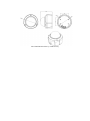
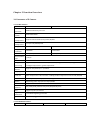
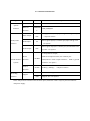
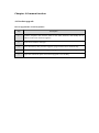
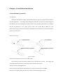
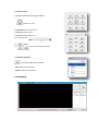
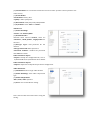
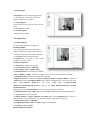
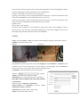
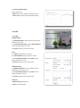
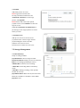
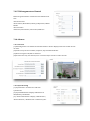
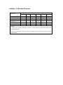
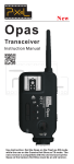
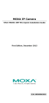
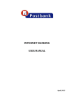
Network Camera User Manual Contents Chapter 1 Warning .......................................................................................................................... 3 Chapter 2 Product Overview .......................................................................................................... 5 Chapter 3 Function Overview ......................................................................................................... 8 3.1 Parameter of IP Camera .................................................................................................... 8 3.2 Hardware Interface ......................................................................................................... 10 Charpter 4 Common function ....................................................................................................... 12 4.1 Product upgrade .............................................................................................................. 12 Charpter 5 Installation Instruction .............................................................................................. 13 5.1 Installation Preparation .................................................................................................. 13 5.2:Installation Instruction: .................................................................................................. 14 Chapter 6 WEB Instruction ........................................................................................................... 17 6.1 System Requirement ....................................................................................................... 17 6.2 Built-in Web Instruction ................................................................................................. 17 6.3 Log in ................................................................................................................................ 18 6.4 Preview............................................................................................................................. 18 6.5 Playback ........................................................................................................................... 20 Chapter 7 Configuration................................................................................................................ 22 7.1 Audio Video Set................................................................................................................ 22 7.2 Camera Set ....................................................................................................................... 24 7.3 VCA ................................................................................................................................... 26 7.4 OSD ................................................................................................................................... 28 7.5 Storage Management....................................................................................................... 29 7.6 Network Management..................................................................................................... 31 7.7 User management ........................................................................................................... 33 7.8 Alarm Management ......................................................................................................... 34 7.9 PTZ Management and Control ........................................................................................ 36 7.10 Advance .......................................................................................................................... 36 Charpter 8 Simple Fault Maintenance.......................................................................................... 38 8.1 System Failure.................................................................................................................. 38 8.2 Network Failure ............................................................................................................... 38 8.3 Operation Failure............................................................................................................. 40 8.4 Control Failure ................................................................................................................. 41 8.5 Video Failure .................................................................................................................... 41 8.6 Audio Failure.................................................................................................................... 41 8.7 Alarm Failure ................................................................................................................... 42 Charpter 9 After-sales Service ...................................................................................................... 43 Charpter 10 Harmful Elements .................................................................................................... 44 Chapter 1 Warning TO REDUCE THE RISK OF FIRE OR ELECTRIC SHOCK, DO NOT EXPOSE THIS PRODUCT TO RAIN OR MOISTURE. DO NOT INSERT ANY METALLIC OBJECT THROUGH THE VENTILATION GRILLS OR OTHER OPENNINGS ON THE EQUIPMENT. Apparatus shall not be exposed to dripping or splashing and that no objects filled with liquids, such as vases, shall be placed on the apparatus. CAUTION EXPLANATION OF GRAPHICAL SYMBOLS The lightning flash with arrowhead symbol, within an equilateral triangle, is intended to alert the user to the presence of “dangerous voltage” within the product’s enclosure that may be of sufficient magnitude to constitute a risk of electric shock to persons. The exclamation point within an equilateral triangle is intended to alert the user to the presence of important operating and maintenance (servicing) instructions in the literature accompanying the product. Battery Batteries(battery pack or batteries installed) shall not be exposed to excessive heat such as sunshine, fire or the like. Disconnection Device Disconnect the main plug from the apparatus, if it’s defected. And please call a repair man in your location. When used outside of the U.S., it may be used HAR code with fittings of an approved agency is employed. CAUTION These servicing instructions are for use by qualified service personnel only. To reduce the risk of electric shock do not perform any servicing other than that contained in the operating instructions unless you are qualified to do so. The BNC Out terminal of the product is provided for easier installation, and is not recommended for monitoring purposes. If you keep the BNC cable connected, a risk of lightening may cause damage or malfunction to the product. Please use the input power with just one camera and other devices must not be connected. Please read the following recommend safety precautions carefully. Do not place this apparatus on an uneven surface. Do not install on a surface where it is exposed to direct sunlight, near heating equipment or heavy cold area. Do not place this apparatus near conductive material. Do not attempt to service this apparatus yourself. Do not place a glass of water on the product. Do not install near any magnetic sources. Do not block any ventilation openings. Do not place heavy items on the product. User’s Manual is a guidance book for how to use the products. The meaning of the symbols are shown below. Reference : In case of providing information for helping of product’s usages Notice : If there’s any possibility to occur any damages for the goods and human caused by not following the instruction Please read this manual for the safety before using of goods and keep it in the safe place. Chapter 2 Product Overview IP Box Camera Size of IP box camera IP IR Bullet Camera ( fixed lens) Size of IP IR bullet camera (fixed lens) IP IR Bullet Camera ( varifocal lens) Size of IP IR bullet camera (varifocal lens) IP IR Dome Camera (fixed lens) Size of IP IR Dome Camera (fixed lens) IP IR Dome Camera (varifocal lens) Size of IP IR Dome Camera ( varifocal lens) Chapter 3 Function Overview 3.1 Parameter of IP Camera 3.1.1 IP Box Camera S3E Series 1.3M core processor operating system Video Compression Audio Compression Image sensor Image resolution Framerate Lens interface type S3E Series 2M ARM9 Architecture processor Embedded LINUX Support H.264 baseline,main profile, M-JPEG G.711/G.726/ADPCM/AAC 1/3 Inch CMOS 1/2.8 Inch CMOS 1280x960 1920x1080 960P@30 F/S 1080P@30 F/S C/CS,DC WDR 100dB Image Support NIR,3D noise reduction,de-interlace,image enhancement, edge enhancement, processing backlight compensation, gamma adjustment Electronic Shutter Support auto/manual,1s~1/10000s Day/Night ICR code rate Video Compression code rate:32K~16M bps,Audio Compression code rate:8k,32k,48K interface Two-way audio,alarm input,TF card,analog video option POE,analog video output,alarm output,RS485 Network Port 10M/100M Ethernet interface Network protocol IVA Ingress Protection power TCP/UDP/HTTP/MULTICAST/UPnP/NTP/RTSP/Onvif support tripwire, Perimeter TVS 4000V lightning protection Not include,suggest DC12V ±10% 3.1.2 IP IR Bullet Camera: S3E Series 1 M S3E Series 1.3 M S3E Series 2M core processor operating system Video Compression Audio Compression Image sensor Image resolution Framerate Lens interface type ARM9 Architecture processor Embedded LINUX Support H.264 baseline,main profile, M-JPEG G.711/G.726/ADPCM/AAC 1/4 Inch CMOS 1/3 Inch CMOS 1/2.8 Inch CMOS 1280x720 1280x960 1920x1080 720P@30 F/S 960P@30 F/S 1080P@30 F/S fixed lens/varifocal lens for option WDR 100dB Image Support NIR,3D noise reduction,de-interlace,image enhancement, edge enhancement, processing backlight compensation, gamma adjustment Electronic Shutter 100dB 100dB Support auto/manual,1s~1/10000s IR Distance 30-50m Day/Night ICR code rate Video Compression code rate:32K~16M bps,Audio Compression code rate:8k,32k,48K interface Two-way audio,alarm input,USB option POE,analog video output,alarm output,RS485 Network Port 10M/100M Ethernet interface Network protocol IVA Ingress Protection power TCP/UDP/HTTP/MULTICAST/UPnP/NTP/RTSP/Onvif support tripwire, Perimeter IP66, TVS 4000V lightning protection Not include,suggest DC12V ±10% 3.1.3 IP IR Dome Camera: S3E Series 1 M core processor operating system Video Compression Audio Compression S3E Series 1.3 M ARM9 Architecture processor Embedded LINUX Support H.264 baseline,main profile, M-JPEG G.711/G.726/ADPCM/AAC S3E Series 2 M Image sensor Image resolution Framerate Lens interface type 1/4 Inch CMOS 1/3 Inch CMOS 1/2.8 Inch CMOS 1280x720 1280x960 1920x1080 720P@30 F/S 960P@30 F/S 1080P@30 F/S fixed lens/varifocal lens for option WDR 100dB Image Support NIR,3D noise reduction,de-interlace,image enhancement, edge enhancement, processing backlight compensation, gamma adjustment Electronic Shutter 100dB 100dB Support auto/manual,1s~1/10000s IR Distance 20-30m Day/Night ICR code rate Video Compression code rate:32K~16M bps,Audio Compression code rate:8k,32k,48K interface Two-way audio, alarm input, alarm output, camera recording for option option POE,analog video output,alarm output,RS485 Network Port 10M/100M Ethernet interface Network protocol Ingress Protection TCP/UDP/HTTP/MULTICAST/UPnP/NTP/RTSP/Onvif All aluminum, TVS 4000V lightning protection IVA support tripwire, Perimeter power Not include,suggest DC12V ±10% Please take the actual device as the standard 3.2 Hardware Interface 3.2.1 Interface Introduction type function name power DC12V description DC12V±10% System interface Ethernet ETHERNE interface T Video output Audio/video interface VIDEO OUT Audio input IN Audio output OUT 10M/100M,RJ45 BNC(Q9)interface, 75Ωp-p analog video signal output (only box camera) linear signal input,G is common port,input voltage ≤1V; (for option) linear signal output,G is common port, should with active speaker(for option) 1-ch input&1-ch output, Alarm extend interface interface ALARM OUT,COM are alarm output interface ; COM is ground terminal(for option) (option) Control interface Recording interface IN&G alarm input interface,G is common port RS-485 A:485(+), B:485(-);(only box camera) TF CARD Micro SD max support 32G USB Support 32G(for option) support Notes: Only Vari-focal Camera owns all these ports; Fixed len camera only has ports for Ethernet and power supply. Charpter 4 Common function 4.1 Product upgrade How to upgrade the version of product step description 1 Connect computer and network video to the same network, and modify the ip address to the same network segment. 2 Input device address and login 3 Select kernel file(*.bin) and start upgrade, program will restart automatically 4 Select web file(*.box) and start upgrade, program will restart automatically 5 Login web-advanced option and check if upgrade is successfully Charpter 5 Installation Instruction 5.1 Installation Preparation 1. Preparation All electrical work must comply with the latest electrical codes, fire regulations and relevant laws and regulations; According to the packing list check if all accessories are in the package and determine the location of the high speed dome camera and installation applications are consistent with the requirements; if not match, please contact your dealer. Please follow the work environment requires the use of the product. Depending on the circumstances actually required to prepare your own tools. 2. Necessary Tools: Fig 4.1.1Tools 3. Check the installation location space and intensity Please make sure the location has sufficient space and intensity to install. The ceiling, wall or bracket must be able to bear 4 times the weight of the IP camera itself. 4. Please save all packaging material Please well keep the original packing materials, in order to send back if any problem. ★ Note: Non-original packing material may result in accidental damage in transit. 5.2:Installation Instruction: 5.2.1 HD IP Box Camera: Taking wall mount as example HD IP Box Camera Installation Steps: 1, Mark the installation holes in the wall by ink pen 2, Drill holes in marked points. 3, Plug the expansion bolts into the holes. 4 Screw the bracket fastened to the wall. 5, Fix two nut screws aligned camera position and rotate tight. Adjust bracket gimbals to appropriate location. 5.2.2 HD IP IR Bullet Camera (Fixed&Varifocal): Taking wall mount as example HD IP IR Bullet Camera Installation Steps: 1, Mark the installation holes in the wall by ink pen 2, Drill holes in marked points. 3, Plug the expansion bolts into the holes. 4 Screw the bracket fastened to the wall. 5, Fix two nut screws aligned camera position and rotate tight. Adjust bracket gimbals to appropriate location. 5.2.3 HD IR Dome Camera (Fixed): Taking ceiling mount as example HD IP IR Dome Camera(Fixed) Installation Steps: 1, Take out camera and unscrew the three screws on the housing, remove the bottom chassis 2, Mark the installation holes in the wall by ink pen 3, Drill holes in marked points. 4, Plug the expansion bolts into the holes. 5, Fix the three φ5 screws on dome camera and fasten on the wall. Assemble the components removed from the first step. Adjust the lens direction to the proper position and tighten the three screws. 5.2.4 HD IR Dome Camera (Varifocal): Taking ceiling mount as example HD IP IR Dome Camera(Varifocal) Installation Steps: 1, Paste positioning on the wall 2, Punch holes on marked points and plug in expansion bolts. 3, Loose the three screws and remove dome cover, fasten the dome base on ceiling. 4, Adjust camera lens to the proper angle, and tighten the screws 5, Aligned cover with mount position, adjust black hood position and tighten the screws. Chapter 6 WEB Instruction 6.1 System Requirement IP camera web settings support WindowsXP,Win7 and Win8 system, please make sure right installation and setup of following items: (1)Display resolution: 1400 * 900 or higher, color: High Color (32-bit). (2)Please make sure the Windows system install the necessary character style. 6.2 Built-in Web Instruction When using the network video products for the first time, an ActiveX control is needed. (1)Login IP address and enter to ActiveX download interface (2)Download ActiveX and click 【Run】to install; (3)Shot down the WEB before installation and click【Next】. (4)Input IP address of camera and allow to add plug-in after installation success. (5)When you success to load plug-in, it shows page as below. Then please enter ID, password. Note: Please ensure IE version above 6.0. And do not use any other browser except Firefox and Chrome. 6.3 Log in (1)Default user name is “Admin” (2)Default password “1111” (3)If you want to change port number, please enter right port number after IE shows port number after you success to log in. 6.4 Preview 6.4.1 Preview page Descriptions of live view parameters and toolbar Icon Description Icon Major stream Description Manual recording on / off, and default storage path is D\NetVideoBrowser\ Minor stream Manually capture, and default storage path is D\NetVideoBrowser\ Third stream Intercom on/off Screen lock Full screen Screen adapt to current Audio on, volume adjustment resolution and mute Note: When stream type is【Pure Video】,audio preview is invalid. 6.4.2Video parameter (1)<Default> to resume the default settings. (2)According to network situation you can choose preview mode from <Low bandwidth>, <Low latency> to <High quality>, <High fluency> 6.4.3 PTZ control (1)Select rotation direction of speed dome, enable auto scan. (2)<Zoom>Zoom in /Zoom out (3)<Focus> Manual Focus. (4)<Iris>Manually adjust iris. (5) set PTZ speed (6) Wipper (7) Preserved for future functions 6.4.4 Preset position Search the target preset number <Set> Setup preset position <Call>Call the preset position 6.5 Playback 6.5.1 Search recording files (1)Select date in the calendar (2) <File Type> select <Record> or <Picture> (3)<Rec Type> Select targeted file type video/picture. 6.5.2 Descriptions of playback toolbar con Description Stop recording Icon Description Clip video files, and default storage path is D\NetVideoBrowser\ Speed down in Single screen 1/2X,1/4X,1/6X and 1/8X Play Playback in 4 screen at the same time Speed up in 2X,4X,6X and 8X Full Screen Playback by frame Download recording files Audio on, volume adjustment Download files into FTP and mute server Capture, and default storage Preview download status path is D\NetVideoBrowser\ 6.6 Log (1)<Channel No> Select target channel (2) <Log type> All/system/warning/alarm/operation/user/others (3) <Start time> Select start date and time. (4) <End time> Select end date and time. (5) <Query> Get a log list. (6) Check logs by <First page><Pre page><Next page><Last page> and <Jump to>target page. (7)<Export current page> to export logs, and default save path is D\NetVideoBrowser. (8)<Export all page> to export all the pages query, and default save path is D\NetVideoBrowser. Chapter 7 Configuration Attention: All settings will be enabled in 3 seconds after <save>. 7.1 Audio Video Set 7.1.1 Video Parameter <Channel No.>Select the target channel General Set (1)<Stream Type><Audio Video>/<Pure Video> (2)<Encoding Mode> <Static code rate> Fix stream and bandwidth occupation. <Dynamic code rate> Stream will be varied to the change of video, take up less bandwidth when there is no change on video. (3)<Video Quality>only be activated when choose <Dynamic code rate> in <Encoding Mode>. <Video Quality><Best>,<Better>,<Good>,<Fair>,<Poor> The better quality the more stream and bandwidth occupation. (4)<Bit Rate> show stream rate for the video, unit is Kbps. When choose<Static code rate>, <Bit Rate>stand for actual rate of the stream. When choose<Dynamic code rate>,<Bit Rate>show the max stream rate, range from 32 ~ 8000Kbps. (5)<Frame Rate> 1/5/10/15/25/30fps optional. (6)<I Frame Rate> To set the interval time for each two I frame. (I frame is the key frame in the video stream) (7)<Prefer Mode> <Frame Rate> Fluency first <Quality> Video quality first (8)<Resolution> 4CIF/VGA/720P/960P/1080P. (9)<N/P Mode> Select <PAL> or<NTSC>. Advance Set (1)<Video Encoding> <H.264> and <Motion JPEG> (2)<Extended Code> Available when selected <H.264>, there are <baseline>, <main profile>, <high profile> for selection. (3)<Encrypt Type> Add password for the channel. <Encrypt Password> Enter password. <Password Confirm> Confirm the password. Click<Save>to enable. Video Parameter-Export <Export> backup the configuration file, save to D\NetVideoBrowser\VideoParam.dat as default. Video Parameter-Import <Import> import the backup file for parameter configuration. Audio Parameter (1)<Channel No.>select target audio channel. (2)<Audio Encoding> select audio compression type. (3)<Audio Sample Rate> <8k>,<32k>,<64k> optional. (4)<Save> save and enable the setting. Note: some models need reboot after saving the setting. 7.1.2 Key Region <Key Region> To have better image quality for some regions on the video, there are 4 regions settable for each video. (1) <Draw Region> Use the mouse to draw the key region on the video. (2)Click<Save> to enable. (3) <Delete Region> delete the drawn regions. 7.2 Camera Set 7.2.1 HD Parameter Set video image parameter in this page. HD Param-Model The system provides 8 video templates for different application, all the video parameter can only be revised and saved in the template. (1) <Current> Select current template. (2)<Name>show the name of the current template, it can be revised. HD Param-Parameter (1)<Sharpness> Range from 0 to 255. (2)<Focus Mode><Auto>or<Manual>. (3)<Day/Night><Auto>,<Night>,<Day>. (4)<ICR-Sensitivity> set sensitivity for IR filter, <Low>, <Middle>, <High> optional. The higher value you set, the faster the IR filter switch. (5)<Digital De-noise> revise the gamma value of image. <Digital De-noise>has options of<Close>,<Ordinary Mode>and<Expert Mode>, default is <Clode>.When selected<Ordinary Mode>,there will be a sliding block to set the de-noise level. When selected<Expert Mode>,there will show sliding block for<Space-Domain Denoise>and<Time-Domain Denoise>, drag to set <Space-Domain Denoise>and<TimeDomain Denoise>. Remark Click button<Save Schedule> to save all the setting into the template. (6)<Wide Dynamic><ON>,<OFF>. When selected<ON>, it will enable setting for<Level>,there are High/Medium/Low for selection. (7)<White Balance ><Auto>,<Manual>and<ATW>.When selected<Manual>,there will be 2 sliding blocks to set the white balance, R stand for red gain and B stand for blue gain. (8)<Exposure><Auto>and<Manual> (9)<Light Suppression> <ON>and<OFF>, suppress the high light. (10)<Defog> <ON>and<OFF> HD Param-Restore Defaults Click button<Restore Default>to recover the defaults setting for the target template. Remark <HD Param> has Export and Import function, operation is the same as <Video Param>. 7.2.2 HD Schedule To define different video template used for different time period. (1)It offers 8 different time periods, select the check box to enable it. (2)Select template for each time period. (3)Length of each time period is settable. Colors are different for different template. (4) Click<Save>to save and enable. 7.2.3 Color to black <Color to black> switch from color to black&white. Color to black - Color <Color>IP camera always display color image and never switch to black&white. Color to black - Black&white <Gray> IP camera always display black&white image and never switch to color. Color to black - Timer: <Timer> IP camera display color image at day time and black&white at night time. (1)Select <Timer> in the list of<Color to gray type>. (2)<Day range>Time for black&white switch to color, default is 6:00. (3)<Night range>Time for color switch to black&white, default is 18:00. (4) Click <Save>. Note: Night range must be later than day range. Color to black - Auto inside: <Auto inside> IP camera will detect brightness of the video image automatically. If the brightness value is more than day range, the video switch from black&white to color. If the brightness value is less than night range, the video switch from color to black&white. (1)Select <Auto inside> in the list of <Color to gray type>. (2)<Gray to color delay> unit is second, which means it delays for a certain seconds before video switch from black&white to color. The default value is 10 seconds. (3)<Color to gray delay> unit is second, which means it delays for a certain seconds before video switch from color to black&white. The default value is 10 seconds. (4)Click <Save> Color to black - Auto outside: IP camera detects brightness of environment by using camera sensor. If the brightness value is more than day range, the video switch from black&white to color. If the brightness value is less than night range, the video switch from color to black&white. 7.3 VCA <VCA>, also called <IVA> / <IVS>, to setup the video intelligent analysis of speed dome camera. <Enable> enable the VCA function. Tripwire Perimeter 7.3.1 Event Parameters The speed dome camera supports 2 rules of VCA<Tripwire> and <Perimeter>. <Tripwire> Draw a tripwire on the screen, when objects cross the tripwire, it would trigger alarm; <Perimeter> Draw an area on the screen, when objects enter it will trigger alarm. (1)<Enable> enable VCA function on current channel. <Valid> activate the rules and start setting. <Rule Name>Give a rules name(max to 16 characters). Notes Max 2 rules available on the same video channel. (2)<Event Set> Choose the rules <Tripwire>/<Perimeter>. <Detect Mode> For <perimeter> detection, include <Intrusion>/<Enter>/<Leave>. <Intrusion> alarm when object come in/out. <Enter> alarm when object come in. <Leave> alarm when object go out. (3)<Show Alarm Count>show the total alarm times. <Show Alarm Rule>show the tripwire/perimeter on video. <Two-way Alarm>when selected <Tripwire>, choose the”two-way alarm”, then two directions cross will both trigger alarm. <Line Clear>clear current lines drawn on video. <Rule Clear>clear current rule. (4)<Save>Save and enable the VCA setting. Notes VCA will be activated in the whole week as default. For specific setting on alarm schedule, please go to <Alarm Set>. 7.3.2 Alarm Set Setup VCA activation schedule. (1)<Channel No.> select the target channel <VCA Enable> Indicate the VCA status of the current channel. (2)<Rule ID> Connected to the setup VCA rules in <Event Param>, when select rule ID, it will bring out setup information of <VCA Enable>, <Rule Name> and <Event>. <Enable> Enable the setting of <Schedule> to setup the day and time of the VCA activation. (3)<Schedule> Schedule alarms. 4 time periods selectable in a day. <Apply> enable the setting. (4)<Link Type> <Link Out> alarm output. <Link Rec> activate recording. <Link Snap> activate snapshot. <Save> Save to enable setting. 7.3.3 Alarm Information Check alarm info. <Reset>Clear alarm numbers of the VCA rule. <Clear>Delete all the alarm information in list. 7.4 OSD 7.4.1 OSD Channel Name (1)<Channel Name> Input channel name, then it will show on screen. (2) <Customize Position> drag <Channel Name> to the target position on screen. (3)<Color> Choose your favorite color. Date (1) <Date> Display date on screen. (2) <Show Week> Display week on screen. (3) <Customize Position> drag <Date> to the target position on screen. (4)<Color> Choose your favorite color. Additional Text (1)<Additional Text> 5 areas available to put additional text on the screen. (2) <Customize Position> drag <Date> to the target position on screen. (3)<Color> Choose your favorite color. OSD Size <Adjust-Self> Edit OSD size. <Save> Save all settings. 7.4.2 LOGO Add LOGO picture on screen. Notes logo picture format must be .bmp, and must be follow the size. <LOGO File>,<Browse> to select logo picture, and<Upload> Notice Device will restart after upload (1)After restart, select<Enable> to show the logo on screen. (2)Enable<Customize coordinate Pos> to put the logo on the target position on screen where you click. 7.4.3 Video Cover Add up to 4 cover areas on the screen. (1)<Channel No.> Choose target channel. (2)<Draw Region> Check to enable. (3)Draw cover area on screen (4)<Clean Area> Delete all cover areas. 7.5 Storage Management 7.5.1 Record Policy Setup recording schedule. (1)<Channel No.> Choose target channel. (2)<Record Status> Display current record status. (3)Select recording type(multiple-choice) <Manual Rec> Check to start recording. <Alarm Rec> Recording will be activated by alarm. <Task Rec> Timing recording, 4 time periods settable for one day. (4)<Offline Video> When it is ON, the device will follow the schedule of <Task Rec> when offline. (5)<Save> Save. 7.5.2 Pre-recorded Alarm <Pre-recorded Alarm> record before alarm, or continue to record after alarm. (1)<Channel No.> Target channel. (2)<Pre-recorded Alarm> Check to enable. (3)<Pre-record Time> Record before alarm. (4)<Record Delay> Continues to record after alarm. (5)<Save> Save. 7.5.3 Storage Set <Pack by time> Pack the record files by time. <Free Disk> Pack the record files by size. <Strategy> Select how to handle the record files when the disk is full. <Stop Rec> Stop record new files. <Cycle Del> Delete the earliest record files. <Cycle Del (Except Alarm)> Delete the earliest record files except event record files. <Save> 7.5.4 Snapshot Set (1) <Channel No.> Select target channel. (2)<Timing capture> Enable timing capture (3)<Interval(s)> Set how much internval times between two snapshots. (4)<Link FTP>snapshot and upload to FTP server. (5)<Link Email>snapshot and send to target email. (4)<Save> 7.5.5 Disk Information <Initialize Disk> format the disk 7.5.6 Network Storage (1)<Device No.> Select disk. (2)<Status> Show current disk status information (3)<Usage> Shows purpose of disk. (4)<IP Address> Setup IP address of <Network Storage>. (5)<Mapping Path> Setup disk path of mapping. (6)<Total Size(M)> Shows used and total capacity of the disk. (7)<Save> 7.6 Network Management 7.6.1 Cable Network <DHCP> check to enable DHCP server will automatically allocate IP address for devices. <IPv6> Display IPV6 address and subnet mask. <MTU> Maximum Transmission Unit, range from 500~1500, default value is 1500. <Ethernet Rate> Select mode and rate of Ethernet card, default mode is <Automatic Detection>, speed unit is MB. Notes: Devices will restart after change <Ethernet Rate>. 7.6.2 Registration Center Keep same settings as what you register in DDNS website (www.myvideo.com). 7.6.3 Network Service DDNS Keep same settings as what you register in DDNS website(suggested: www.myvideo.com). FTP Make sure to insert the memory card. PPPoE Check to enable PPPoE function, enter User name and confirm password. NTP <NTP Server> enter server address. <Port> enter NTP server port. <Interval> update interval. Others Set Http and Https port, Enable UPnP and SNMP functions. 7.6.4 IP Filter Blacklist User want to block some IP address, select<Block the Following IPs>, input the block IP address and<Add>,<Save>.Max to add 16 blacklist IP address. Caution: Please don’t add your own IP address in blacklist, otherwise you will not be able to login. Whitelist User want to allow only some IP address, select <Allow the Following IP>, input trusted IP address, <Add> and <Save>. Max to 16 whitelist IP address. Caution: Once enable the whitelist function, please make sure to add your own IP address in whitelist, otherwise you will not be able to login the device. Cancel blacklist or whitelist Anytime click<Allow All> and <Save> to cancel all the blacklist and whitelist. Note: Please restart device after setup blacklist or whitelist. 7.7 User management 7.7.1 Add User <User name> add user, only English letter and figure are available. <Password> only English letter and figure are available. <Authority>: Browse: Can only watch the videos. browse+ control: Watch video and control PTZ. browse+ control+ set: Allow all operation except user management. Administrator: All operations available. 7.7.2 Modify password Select the user you want to modify in the user list, click <Modify Pwd>,input the old password, new password, password confirmation, then click<Modify>. 7.7.3 Delete User Select targeted user in user list and click【Delete】 to delete. 7.8 Alarm Management 7.8.1 Alarm Input IP Camera alarm input only has port1, alarm mode include closed circuit alarm and open circuit alarm. <ON>is closed circuit alarm. <OFF>is open circuit alarm. <Link Out>/<Link PTZ> activate alarm device or PTZ. 7.8.2 Alarm Output Alarm output only has port 1. <ON>is closed circuit alarm. <OFF>is open circuit alarm. 7.8.3 Motion Alarm (1)<Set Motion Detection Area> Check to draw area on screen. (2)<Clean Area> Clean drawn area. (3)<ICR-Sensitivity> set detection sensitivity, range from 0100, 100 means the highest sensitivity. (4)<Schedule> setup alarm arm schedule. (5)<Link Out> set alarm activation. 7.8.4 Lost alarm Alarm when video lost. (1)Check to enable lost alarm for target channel. (2)<Schedule> Setup alarm arm schedule. (3)<Link Type> Link PTZ/no link. (4)<Link Channel> (5)<Link PTZ Type> no link/preset position/pattern/auto Tour. 7.8.5 Cover Alarm Alarm when camera lens is covered. 7.8.6 Email Alarm (1)<Email Alarm Enable> check to enable sending email after alarm. (2)Set sending email information: <SMTP server> <SMTP port><Email Account><Email Password> (3)<Email Mode> (4)Input receive email address, support up to 4 email address. 7.8.7 Alarm Server Set alarm server’s IP address and port number, 7.9 PTZ Management and Control PTZ management mode: <Serial Port Set>and<Protocol Set> <Serial Port Set>: <Port Name>,<Baud Rate>,<Parity>,<Byte Size>,<Work Mode> <Protocol Set>: <Channel>,<Port Name>,<Protocol>,<Address> 7.10 Advance 7.10.1 Local set (1)<Showing frame-rate and bit-stream information> check to display frame rate and bit stream on video. (2)Set the save path of record files, snapshot, clips and download files. (3)<Protocol Type> TCP, UDP or multicast. (4)IP camera has only one channel, user can choose major stream or minor stream. 7.10.2 System setting (1)<System Time> Set time zone and time synchronous. (2)<SystemInformation>Display information of CPU,Memory and FLASH. (3)< Version Information >Display <SDK Version>, <Kernel Version>, <Web Version> and<Factory ID>. 7.10.3 System Maintenance System maintenance includes <Equipment Control>and <Version Upgrade>. (1)<Equipment Control> <Restore> Reset to factory default. <Reboot> Reboot the device. (2)<Version Upgrade> upgrade new firmware. (firmware format: .box/.bin) Upgrade process normally needs a few minutes until indication for completion. Caution: Please strictly follow the instruction by technical specialist for firmware upgrade. 7.10.4 Access Platform PU set user can set the IP address and port number of<Register Server>,<Heartbeat Server>,<Alarm Server>and VSP’s port number and VAP’s port number. <Channel No. >support<Auto Filling Setting>function. PU set support 【SIP】protocol setting. IP cameras support onvif V10, user can choose <Enable>. Charpter 8 Simple Fault Maintenance 8.1 System Failure 8.1.1 Not able to recognise U-disk or SD card Possible Reason: Disk partition information has problem, which cause no recognition, need formatting for the disk; Loose connection, re-plug U-disk/SD card and reboot the camera; For portable disk, it may fail when there is not enough power, need to check the power supply method to make sure enough power supply or change to use independent power supply disk. 8.1.2 No recognition on Wireless Network Card Possible Reason: Static turn the network card into protection state, need to reboot the camera; Unstable condition on the network card, need to replace for new network card. 8.1.3 Straight connect is ok, but no connection on Switch Possible Reason: NIC crystals prohibit or damage, need replace for new one. 8.2 Network Failure 8.2.1 Camera was power on but cannot be found on IP searcher Troubleshooting steps: Check status of computer/host NIC, NIC driver, network wire, and network connection, make sure all are correct; Directly connect the camera to computer/host server to check it works or not, reset the computer/host server and try again; Try another camera or another computer/host server; Please contact us. 8.2.2 No image on IE <IE setting> It needs to download and install the ActiveX plug-in for IE browsing at first connection, and do the correct setting on IE as following: Open IE, click “Tools” - “Internet Options” - “Security” - “Internet” - “Custom Level”, enable all the items on AcitveX control and plug-in; IE setting “Security”-“Local Intranet”-“Custom Level”, enable all the items on AcitveX control and plug-in; Add IP address of the camera into “Trusted sites”,“Security”-“Sites”- enter IP address, add and cancel the selection of “Require server verification” at the bottom. 【Attention】 It is recommended to use IE browser with version higher than v6.0 to make sure cameras work properly. 8.2.3 Incorrect image after login Possible Reason: There is other device in the some network with same IP and Mac address. Troubleshooting steps: Disconnect the camera, try to ping the network to check whether there is return package. Use the IP searcher to check whether there are devices with same IP address, then disconnect the other devices to make sure the IP address of the camera is unique. 8.2.4 It is ok to ping the server, but cannot properly login. Troubleshooting steps: Port 3001 is banned by the firewall; Wrong port number is incorrect when logging in; Wrong ID and password; Too many access to the camera. Use IP searcher to check the listen port of the camera, make sure it is the same as the software. 8.2.5 UDP unable to connect video Possible Reason: Other client already connect to the camera on the same computer; UDP port conflict with other application program on the same computer, revise camera IP address and test again. 8.2.6 Video of two camera appear alternately, or connect and disconnect in sometime Possible Reason: Conflict on IP address, check on the IP searcher; Conflict on MAC address, check on IP searcher; Camera IP address conflict with other computer IP address 8.3 Operation Failure 8.3.1 No correct connection of video on IE Troubleshooting steps: Make sure host IP address is in the same network segment with the camera. 【Attention】Make routing if in different network segment. Make sure to use IE at version 8.0 or higher; Make sure driver for graphic card and DirectX are installed properly, it is recommended to install the latest version driver; Make to enable ActiveX plug-in; Turn off Anti-virus software and firewall to test; Delete the installed plug-in, download again and re-install to test; Use another computer/host server to test; Contact us if still had problem. 8.3.2 Cannot connect sub-stream Possible Reason: Resolution of sub-stream is higher than main-stream, need to set as default; Wrong firmware version, need to update; Access to camera are full. 8.4 Control Failure It is able to control Pan/Tilt/Zoom in IE, but cannot control in the software. Troubleshooting Steps: Make sure the control protocol is correct. Possible Reason: Make sure address for PTZ camera is correct set in software Please contact us if problem still remain. 8.5 Video Failure 8.5.1 Video display properly in the software, but it is unstable or intermittent, or lose frame. Troubleshooting Steps: Exit the software, check the CPU utilization of the computer, make sure the computer configuration is capable to run the software and there is no virus; Ping the camera from the computer to check whether there is dropout; Test network bandwidth, if it is not enough or unstable, please contact the Internet Service Provider; Please lower down the resolution or image quality when need fluent video in narrow network bandwidth; Please contact us if it is not resolved. 8.5.2 Connection is correct but screen is black or video image is anamorphic Other issues: No OSD, or image is anamorphic but go normal after full screen. Possible Reason: DirectX version lower than 9.0c; Graphic card driver incorrect, which disable the accessory function of DirectX; Set full screen privacy mask. 8.5.3 Video display properly in IE but abnormal in software Troubleshooting Steps: Please make sure software version is correct; Make sure IP address and server type is correct in software; It is suggested to use “Main stream + TCP” type in LAN, and “Sub-stream +TCP” in WLAN. Make sure video are all connected in the software main interface; Reboot the software to connect again; Please contact us if it is not resolved. 8.6 Audio Failure 8.6.1 Video display and control properly but no audio Troubleshooting steps: Make sure the computer audio card driver and connection is correct, please try to play some music to test; Make sure to selected Video/Audio not only Video in camera setting; Make sure the audio channel is correct; Make sure the microphone is connected properly; Please contact us if it is not resolved. 8.6.2 Weak Audio Signal Make sure using active microphone; Increase the sensitivity of the microphone; Use active loudspeaker for audio playing. 8.7 Alarm Failure 8.7.1 No Alarm Output Make sure output wiring is correct; Power input: voltage—AC110V/DC24V, electricity—1A; Check the setting for input/output port in IE; Make sure the alarm device is working properly Charpter 9 After-sales Service We provide 2 years warranty for all our IP cameras. We provide free repair service in the warranty period except the following circumstances: ● Not follow the User Manual and the incorrect operation cause cameras damage; ● Lightning, fire, and in case of irresistible natural disasters; ● Product damage caused by using poor design matching product from other manufacturers. Statement ● As we will keep our technology up to date, product parameters change accordingly without prior notice. ● We reserves the right for final interpretation of this manual. Charpter 10 Harmful Elements Items name <Electronic Product Pollution Control Management Measures> (Pb) (Hg) (Cd) (CrVI) (PBB) (PBDE) Metal × ○ ○ ○ ○ ○ Plastic ○ ○ ○ ○ ○ ○ PCB × ○ ○ ○ ○ ○ Glass(if has) ○ ○ ○ ○ ○ ○ Power(if has) × ○ ○ ○ ○ ○ Accessory(if has) × ○ ○ ○ ○ ○ Remarks: 1.○ means the restricted substance content is lower than the SJ/T11363-2006 stand ard stipulated limit. 2.×means the restricted substance content is higher than the SJ/T11363-2006 standard stipulated limit.