1
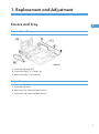
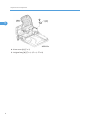
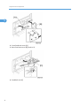
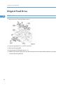
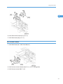
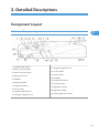
ARDF DF3010/DF3070 Machine Code: B802/D630 Field Service Manual September, 2011 Subject to change Safety and Symbols Replacement Procedure Safety • Turn off the main power switch and unplug the machine before beginning any of the replacement procedures in this manual. Symbols Used in this Manual This manual uses the following symbols. *: See or Refer to : Screws : Connector : Clip ring : E-ring : Clamp 1 TABLE OF CONTENTS Safety and Symbols............................................................................................................................................1 Replacement Procedure Safety.....................................................................................................................1 Symbols Used in this Manual........................................................................................................................1 1. Replacement and Adjustment Covers and Tray.................................................................................................................................................5 Front and Rear Cover.....................................................................................................................................5 Original Tray..................................................................................................................................................5 Document Feed Components............................................................................................................................7 Pick-Up Roller.................................................................................................................................................7 Feed Belt.........................................................................................................................................................7 Separation Roller............................................................................................................................................9 Electrical Components.....................................................................................................................................11 DF Drive Board............................................................................................................................................11 Original Length Sensors and Trailing Edge Sensor...................................................................................11 Original Set, Separation, Skew Correction and Scanning Entrance Sensor..........................................12 Original Width Sensors...............................................................................................................................13 Registration Sensor......................................................................................................................................14 Original Exit Sensor.....................................................................................................................................15 DF Position Sensor.......................................................................................................................................15 Cover Sensor................................................................................................................................................16 Pick-up Roller HP and Original Stopper HP Sensor..................................................................................16 Stamp Solenoid............................................................................................................................................18 Original Feed Drive.........................................................................................................................................20 ADF Feed Motor..........................................................................................................................................20 ADF Inverter Motor......................................................................................................................................21 ADF Transport Motor...................................................................................................................................22 ADF Pick-up Motor......................................................................................................................................22 2. Detailed Descriptions Component Layout...........................................................................................................................................25 Mechanical Component Layout.................................................................................................................25 Electrical Component Layout......................................................................................................................26 Drive Layout..................................................................................................................................................29 Basic Operation...............................................................................................................................................31 2 Original Size Detection...............................................................................................................................31 Mixed Original Size Mode.........................................................................................................................33 Pick-Up and Separation..............................................................................................................................34 Skew Correction..........................................................................................................................................35 Slip Detection...............................................................................................................................................36 Original Transport and Exit.........................................................................................................................37 Conditions for Jam Detection......................................................................................................................38 3. Service Tables Dip Switches.....................................................................................................................................................41 3 4 1. Replacement and Adjustment Covers and Tray 1 Front and Rear Cover 1. Open the left cover [A]. 2. Front cover [B] ( x 1, hook x 2) 3. Rear cover [C] (x 2, hook x 2) Original Tray 1. Open the left cover. 2. Rear cover (* "Front and Rear Cover") 3. Front cover (* "Front and Rear Cover") 5 1. Replacement and Adjustment 1 4. Pivot cover [A] ( x 1) 5. Original tray [B] (x 1, x 1, x 2) 6 Document Feed Components Document Feed Components Pick-Up Roller 1 1. Open the left cover. 2. Bushings [A] ( x 1 each) 3. Pick-up roller [B] (gear x 1, one-way gear x 1) Feed Belt 1. Open the left cover. 7 1. Replacement and Adjustment 1 2. Front feed unit cover [A] 3. Rear feed unit cover [B] (hook x 2) 4. Feed belt unit [C] 8 Document Feed Components 1 5. Slide the tension plate [D] (hook) 6. Belt unit cover [E] ( x 1) 7. Belt tension unit [F] 8. Feed belt [G] Separation Roller 1. Open the left cover. 9 1. Replacement and Adjustment 1 2. Separation roller cover [A] 3. Remove the bushing [B] ( x 1). 4. Slide the separation roller shaft to the front side, and then remove it. 5. Separation roller [C] ( x 1) 10 Electrical Components Electrical Components DF Drive Board 1 1. Rear cover (*"Front and Rear Cover") 2. DF drive board [A] ( x 4, all s) Original Length Sensors and Trailing Edge Sensor 1. Open the left cover. 11 1. Replacement and Adjustment 1 2. Remove the tray stopper [A], while pushing the hook with a screw driver. 3. Open the original tray [B]. 4. Original tray cover [C] ( x 3) 5. Original trailing edge sensor [D] ( 6. Original length sensors [E] ( x 1, hook) x 1 each, hook) Original Set, Separation, Skew Correction and Scanning Entrance Sensor 1. Open the left cover. 12 Electrical Components 1 2. Open the inner upper cover [A] (stepped screw x 3). 3. Original set sensor [B] ( x 1, hook) 4. Separation sensor [C] ( x 1, hook) 5. Skew correction sensor [D] ( x 1, hook) 6. Scanning entrance sensor [E] ( x 1, hook) Original Width Sensors 1. Open the left cover. 13 1. Replacement and Adjustment 2. Open the inner upper cover (* " Original Set, Separation, Skew Correction and Registration Sensor"). 1 3. Original width sensor bracket [A] ( x 2, ground cable x 1). 4. Original width sensors [B] ( x 1 each, hook) Registration Sensor 1. Open the ARDF. 2. White plate [A] (stud screw x 1) 3. Registration sensor bracket [B] ( x 1) 14 Electrical Components 4. Registration sensor [C] ( x 1) Original Exit Sensor 1. Open the left cover. 1 2. Open the feed-in guide plate [A]. 3. Guide plate [B] ( x 2, stepped screw x 1; front side) 4. Original exit sensor [C] ( x 1, hook) DF Position Sensor 1. Rear cover (* "Front and Rear Cover") 2. ARDF drive board (* "ARDF Drive Board") 15 1. Replacement and Adjustment 3. DF position sensor bracket [A] ( x 1) 1 4. DF position sensor [B] ( x 1, hook) Cover Sensor 1. Open the left cover. 2. Rear cover (* "Front and Rear Cover") 3. Cover sensor [A] ( x 1, hook) Pick-up Roller HP and Original Stopper HP Sensor 1. Open the left cover. 2. Rear cover (* "Front and Rear Cover") 16 Electrical Components 1 3. Release the clamp [A] ( x 1), and then slide the harnesses away. 4. Sensor bracket [B] ( x 1, x 2) 5. Pick-up roller HP sensor [C] (hook) 6. Original stopper HP sensor [D] (hook) 17 1. Replacement and Adjustment Stamp Solenoid 1 1. Open the left cover. 2. Remove the platen plate [A]. 3. Stamp solenoid cover [B] ( x 1) 4. Remove the screw [C] ( x 1). • You cannot remove the stamp solenoid at this time. 5. Rear cover (* "Front and Rear Cover") 18 Electrical Components 6. Disconnect the stamp solenoid harness [D]. 7. ADF feed motor (* "ADF Feed Motor") 1 8. Put the stamp solenoid harness into the cutout [E]. 9. Pull out the stamp solenoid [F] 19 1. Replacement and Adjustment Original Feed Drive 1 ADF Feed Motor 1. Rear cover (* "Front and Rear Cover") 2. Harness guide [A] ( x 2, all s, all s) 3. Remove the spring [B]. 4. Stay bracket [C] (stepped screw x 1) 5. Slide the feed motor gear [D] to the left side (seen from the front of the machine), and then remove the timing belt [E]. 20 Original Feed Drive 1 6. ADF feed motor bracket [F] ( x 3) 7. ADF feed motor [G] ( x 1) ADF Inverter Motor 1. ADF feed motor (* " ADF Feed Motor") 2. ADF inverter motor bracket [A] ( x 2, x 1, timing belt) 3. ADF inverter motor [B] ( x 4) 21 1. Replacement and Adjustment ADF Transport Motor 1 1. Rear cover (* "Front and Rear Cover") 2. Ground cable [A] ( x 1) 3. ADF transport motor bracket [B] ( x 2, x 1) 4. ADF transport motor [C] ( x 2) ADF Pick-up Motor 1. Rear cover (* "Front and Rear Cover") 22 Original Feed Drive 2. Harness guide [A] ( x 2, all s, all s) 3. Stay bracket [B] (stepped screw x 1) 4. Release 6 clamps on the ADF pick-up motor bracket [C] ( x 6). 5. ADF pick-up motor bracket [D] ( x 3, 1 x 1) 6. ADF pick-up motor [E] ( x 2, x 1, timing belt) 23 1. Replacement and Adjustment 1 24 2. Detailed Descriptions Component Layout 2 Mechanical Component Layout 1. Original Width Sensor 2. Skew Correction Roller 3. Skew Correction Sensor 4. Separation Sensor 5. Feed Belt 6. Separation Roller 7. Original Set Sensor 8. Pick-up Roller 9. Original Length Sensor 1 10. Original Length Sensor 2 11. Original Length Sensor 3 12. Inverter Roller 13. Junction Gate 14. Exit Roller 15. Original Exit Sensor 16. Transport Roller 17. Registration Sensor 18. Registration Roller 19. Scanning Entrance Sensor 25 2. Detailed Descriptions Electrical Component Layout Sensors and Drive Components 2 1. Original Width Sensors 2. Scanning Entrance Sensor 3. Skew Correction Sensor 4. ADF Transport Motor 5. Left Cover Sensor 6. Pick-up Motor 7. Pick-up Roller HP Sensor 8. Original Stopper HP Sensor 9. ADF Inverter Motor 10. ADF Feed Motor 11. Original Length Sensor 1 12. Original Length Sensor 2 13. Original Length Sensor 4 14. DF Drive Board 15. Original Trailing Edge Sensor 16. Original Set Sensor 17. Stamp Solenoid 18. Separation Sensor 19. Original Exit Sensor 20. Junction Gate Solenoid 21. Registration Sensor Electrical Component Descriptions Symbol 26 Name Function Index No. Component Layout Motors - ADF Feed Drives the feed belt, separation, pick-up, and reverse table rollers. 10 - ADF Transport Drives the transport and exit rollers 4 - ADF Inverter Drives the Inverter rollers 9 - Pick-up Motor Moves the pick-up roller up and down. 6 - DF Position Detects whether the DF is lifted or not. - Skew Correction Detects the leading edge of the original to turn off the DF feed and transport motors. 3 - Registration Detects the original exposure timing, and checks for original misfeeds. 21 - Cover Sensor Detects whether the feed-in cover is opened or not. 4 - Original Width Sensor - S Detects the original width - S. 1 - Original Width Sensor - M Detects the original width - M. 1 - Original Width Sensor - L Detects the original width - L. 1 - Original Width Sensor - LL Detects the original width - LL. 1 - Original Length - S Detects the original length - S. 11 - Original Length - M Detects the original length - M. 12 - Original Length - L Detects the original length - L. 13 - Original Set Detects if an original is on the feed table. 16 Original Exit Detects the leading edge of the original to turn on the junction gate solenoid and checks for original misfeeds. 19 2 Sensors - 27 2. Detailed Descriptions Detects the trailing edge of the original to turn off the transport and feed motor and junction gate solenoid. In single-sided mode, used to detect original misfeeds. - Original Trailing Edge Sensor Detects the trailing edge of the last original to stop copy paper feed and to turn off the transport motor, and checks for original misfeeds. 15 - Separation Sensor The machine uses this sensor to check if the original has slipped during feed-in, to make sure that original feed starts at the correct time. 18 - Stamp Energizes the stamper to mark the original. 17 - Junction Gate Opens and closes the junction gate. 20 DF Drive Interfaces the sensor signals with the copier, and transfers the magnetic clutch, solenoid and motor drive signals from the copier. 14 2 Solenoids PCBs - 28 Component Layout Drive Layout 2 1. Registration Roller 2. Transport Roller 3. Skew Correction Roller 4. Separation Roller 5. Feed Belt 6. ADF Transport Motor 7. Pick-up Roller 8. Exit Roller 9. ADF Inverter Motor 10. ADF Feed Motor 11. Inverter Roller 29 2. Detailed Descriptions ADF Feed Motor 2 • ADF Feed Motor [A] drives the pick-up [B], feed belt [C], separation [D] and skew correction rollers [E]. ADF Transport Motor and ADF Inverter Motor • ADF Transport Motor [A] drives the registration roller [B], transport roller [C] and exit roller [D]. • ADF Inverter Motor [E] drives the Inverter Roller [F]. 30 Basic Operation Basic Operation Original Size Detection 2 The original size detection mechanism consists of the five original width sensors ([A]: Width Sensor SS, [B]: Width Sensor S, [C] Width Sensor M, [D]: Width Sensor L, [E]: Width Sensor LL) and three original length sensors ([F]: Length Sensor S, [G]: Length Sensor M, [H]: Length Sensor L). Based on the combined output of the length sensors and the width sensors, the machine can detect the size of the original. This integrated detection mechanism is detailed in the table below. Size Width Sensor Length Sensor Area SS S M L LL S M L LT A/B A3/SEF (297 x 420) ON ON ON ON ON ON ON ON O O B4/SEF (257 x 364) ON ON ON - - ON ON ON - O A4/SEF (210 x 297) ON ON - - - ON ON - O O A4/LEF (297 x 210) ON ON ON ON ON - - - O O B5/SEF (182 x 257) ON - - - - ON - - - O B5/LEF (257 x 182) ON ON ON - - - - - - O A5/SEF (148 x 210) ON - - - - - - - - O 31 2. Detailed Descriptions 2 A5/LEF (210 x 148) ON ON - - - - - - - O 11" x 17"/SEF (DLT) ON ON ON ON - ON ON ON O1 O5 11" x 15"/SEF ON ON ON ON - ON ON ON 1 10" x 14"/SEF ON ON ON ON ON ON ON ON O - 8.5" x 14"/SEF (LG) ON ON - - - ON ON ON O2 - 8.5" x 13"/SEF (F4) ON ON - - - ON ON ON 2 8.25" x 13"/SEF ON ON - - - ON ON ON - - 8" x 13"/SEF (F) ON ON - - - ON ON ON - - 8.5" x 11"/SEF (LT) ON ON - - - ON - - O3 O6 8.5" x 11"/LEF (LT) ON ON ON On - - - - O4 O7 7.25" x 10.5"/SEF (US EXE) ON ON - - - ON - - O - 10.5" x 7.25"/SEF (US EXE) ON ON ON ON - - - - 4 - 10" x 8"/SEF ON ON - - - ON - - 3 - 5.5" x 8.5"/SEF (HLT) - - - - - - - - O - 5.5" x 8.5"/LEF (HLT) ON ON - - - - - - O - 267 mm x 390 mm ON ON ON ON - ON ON ON - 5 195 mm x 267 mm ON ON - - - ON - - - 6 267 mm x 195 mm ON ON ON ON - - - - - 7 - O Symbols O: Yes (Default), Europe, Asia : Yes (Can select this with SP mode), ON: Paper present, LT: North America, A/B: • For "O/ " mark, which has superscripted number, it is possible to change the original detection size with SP6-016. For example, instead of LT (O3), the machine can be set up to detect 10” x 8” ( 3). • The F size can be selected with SP5-126. The default is 8.5" x 13" • The machine cannot detect more than one size of original in the same job. 32 Basic Operation Mixed Original Size Mode This section explains what happens when the user selects mixed original size mode. Because this ARDF is a sheet-through document feeder, the method for original document width detection is the same as when the originals are the same size, but the document length detection method is different. Therefore, the scanning speed is slightly slower. 2 Document length detection From when the skew correction sensor switches on until it switches off, the CPU counts the transport motor pulses. The number of pulses determines the length of the original. Feed-in cycle When the original size for the copy modes listed below cannot be determined, the image cannot be correctly scaled (reduced or enlarged) or processed until the original’s length has been accurately detected. The length must be determined before the image is scanned. Auto Reduce/Enlarge Centering Erase Center/Border Booklet Image Repeat The originals follow this path: 1. Length detection Scanning glass Inverter table 2. Inverter table Scanning glass Inverter table (restores the original order) 3. Inverter table Scanning glass (image scanned) Exit tray Normal feed-in In a copy mode other than those listed above, when the reduction/enlargement ratio has been determined, the originals are scanned normally. In order to store the scanned images, a large area of memory (the detected original width x 432 mm length) is prepared. Next, only the portion of the image up to the detected original length is read from memory and printed. 33 2. Detailed Descriptions Pick-Up and Separation 2 The original is set with the image facing up. The original pushes actuator and the original set sensor is activated. After pressing the start button, the pick-up motor is activated and the original feed unit [A] moves down. At the same time, the ADF feed motor is activated and the pick-up roller [B] feeds original to the feed belt [C]. After being fed from feed belt [C], the topmost sheet is separated from the stack by the separation roller [D] and sent to the skew correction roller. The mechanism is an FRR system, consisting of the original feed belt [C] and separation roller [D]. 34 Basic Operation Skew Correction 2 When an original is fed into the feeder, the feed motor [A] rotates forwards. At this time, the feed belt turns but the skew correction roller [B] does not, because these rollers have a one-way gear. (If the ADF feed motor rotates forward, the feed belt is moved. If the ADF feed motor rotates in reverse, the skew correction roller is moved.) As a result, when the leading edge of the paper gets to the skew correction roller, skew in the original is removed. A short time after the leading edge of the original turns on the skew correction sensor [C], the feed motor [A] turns off and rotates in reverse. At this time, the skew correction roller [B] and the feed belt [D] both turn, and original feed continues. The registration roller also has the same skew correction mechanism, but only for small size originals (6, A5 or HLT). This function can be effective for all size paper with SP6-020-001. 35 2. Detailed Descriptions Slip Detection 2 [A]: Separation sensor [B]: Skew correction sensor These two sensors are used to measure the amount of slippage and to correct for this. The machine measures the time it takes for the original to get to the separation sensor [A] after the [Start] key is pressed. • If the original arrives at the correct time, it feeds normally. • If the original arrives late, the machine enters the slip mode. In the slip mode, the machine measures the time for the leading edge of the original to move from the separation sensor to the skew correction sensor [B]. The machine uses this time to adjust the length of time that the entrance roller stays off to correct skew. This stops feed for enough time for the original to be in the correct position for feeding. 36 Basic Operation Original Transport and Exit Single-Sided Originals 2 The feed motor feeds the separated original to the skew correction roller [A] at maximum speed. After skew correction, the feed and transport motors feed the original through the scanning area at a lower speed (the scanning area contains the original exposure guide [B] and DF exposure glass [C]). After scanning, the original is fed out by the transport roller [D] and exit roller [E]. Double-Sided Originals After skew correction, the ADF feed and transport motors drive the skew correction roller [A], registration roller [B], transport roller [C] and the exit roller [D]. The front side of the original is then scanned. When the original exit sensor [E] detects the leading edge of the original, the junction gate solenoid is activated and the junction gate [F] opens. The original is then transported towards the inverter table. Soon after the trailing edge of the original passes the exit sensor, the junction gate solenoid switches off and the junction gate [F] is closed. When the original has been fed onto the inverter table, the ADF inverter 37 2. Detailed Descriptions motor switches on. The original is then fed by the inverter roller [G], and then by the skew correction roller [A] and registration roller [B] to the scanning area (where the reverse side will be scanned). 2 The original is then sent to the inverter table [H] again to be turned over. This is done so that the duplex copies will be properly stacked front side down in the exit tray [I] in the correct order. Original Sensor During one-to-one copying, copy paper is fed to the skew correction roller in advance (while the original is still being scanned), to increase the copy speed. The original set sensor monitors the stack of originals in the feeder, and detects when the trailing edge of the last page has been fed in. The main CPU then stops the copier from feeding an unwanted extra sheet of copy paper. Conditions for Jam Detection Jam Mode Detection Timing When turning on the machine, the skew correction sensor, separation sensor, registration sensor or exit sensor detects an original. Initial When the cover is closed or DF is down, the skew correction sensor, separation sensor, registration sensor or exit sensor detects an original. When the cover is opened or DF is lifted up, the skew correction sensor, separation sensor, registration sensor or exit sensor detects an original. Sensor stays on too long 38 The skew correction sensor does not turn off even if the original was fed by the maximum length of the original + 150 mm after the skew correction sensor turned on. The registration sensor does not turn off even if the original was fed by its length x 1.5 after the registration sensor turned on. Basic Operation The exit sensor does not turn off even if the original was fed by its length x 1.5 after the exit sensor turned on. The separation sensor does not turn on even if the original was fed by transport path length x 1.5. Sensor does not come on The skew correction sensor does not turn on even if the original was fed by transport path length x 1.5. 2 The registration sensor does not turn on even if the original was fed by transport path length x 1.5 after the skew correction sensor turned on. The exit sensor does not turn on even the original was fed by transport path length x 1.5 after the skew correction sensor turned on. 39 2. Detailed Descriptions 2 40 3. Service Tables Dip Switches DIP-SW Function 1 2 3 4 0 0 0 0 Normal operating mode (Default) 0 0 0 1 Free run: With original: One-sided mode: 100% speed 0 0 1 0 Free run: With original: Two-sided mode: 100% speed 0 0 1 1 Free run: No original: One-sided mode: 100% speed 0 1 0 0 Free run: No original: Two-sided mode: 100% speed 0 1 0 1 Free run: With original: One-sided mode: 32% speed 0 1 1 0 Free run: With original: Two-sided mode: 32% speed 0 1 1 1 Free run: With original: One-sided mode: 70% speed 1 0 0 0 Free run: With original: Two-sided mode: 70% speed 1 0 0 1 Free run: With original: One-sided mode: 200% speed 1 0 1 0 Free run: With original: Two-sided mode: 200% speed 1 0 1 1 Transport Motor On 1 1 0 0 Feed Motor On 1 1 0 1 Transport Motor On with random mode 1 1 1 0 Feed Motor On with random mode 1 1 1 1 3 41 MEMO 42