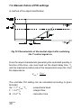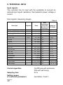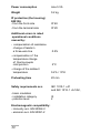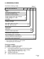
1
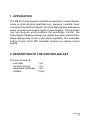
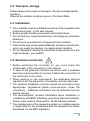
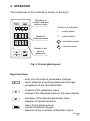
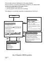
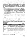
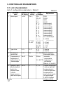
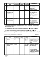
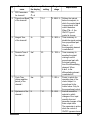
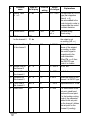
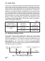
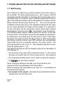
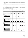
MICROPROCESSOR CONTROLLER RE18 C E R T Y SERVICE MANUAL F I K A T Contents: 1. Application .......................................................................... 3 3. Installation .......................................................................... 4 4. Operation .......................................................................... 11 5. Parameters ....................................................................... 14 5.1. Table of parameters .................................................... 14 5.2. Alarms ....................................................................... 19 5.3. Cycle time ................................................................... 20 5.4. Heating-cooling control .............................................. 20 5.5. Valve control ............................................................... 21 5.6. Security codes ............................................................ 21 6. Special functions ............................................................. 22 6.1. Selecting special functions ......................................... 22 6.2. Manual control ............................................................ 22 6.3. Tuning ......................................................................... 23 6.4. Measurement of two-wire line resistance ................... 23 6.5. Return to the factorys settings ................................... 23 7. Tuning ............................................................................... 24 7.1. Self-tuning .................................................................. 24 7.2. Manual tuning ............................................................ 26 8. Technical specifications ................................................. 28 9. Ordering codes ................................................................ 31 10. Maintenance and guarantee ........................................... 32 1. APPLICATION The RE18 microprocessor controller is intended to control temperature or other physical quantities e.g.: pressure, humidity, level, converted into electrical signal. The controller displays processing value, set point and output signal on two displays. The controller has two outputs what enables the two-stage control, the three-stage of heating-cooling type control, the valve control ( threestage step-by-step control ) and alarm signalling. The automatic setting choice of the PID controller ensures an optimal control quality. 2. DESCRIPTION OF THE CONTROLLER SET The set consists of: - controller - service manual - guarantee certificate - holders 1 pc 1 pc 1 pc 2 pcs ! 3. INSTALLATION Prepare a cut-out of 92+0,6 x 45+0,6 mm in the panel. The panel material thickness should be up to 6 mm.The controller should be placed from the front of the panel with the power supply switched off. After the controller is fixed, fasten it with holders. max 93 8 69 96 48 max.6 Fig 1. RE18 Controller overall dimensions. The RE18 controller fulfils requirements concerning the service safety in accordance with EN 61010 standard and EMC immunity against interference occurring in the industrial environment containing a certain amount of noise in the form of transient voltages and spikes according EN 50082-2 standard. This electrical noise can enter and adversely affect the operation of microprocessor-based controls. Different interference sources occuring practically, influence the controller indications in a continuous or pulse way from the side of the main supply (as the result of other device actions) and also overlaps the measured signal or controller auxiliary circuits. " Interference also arises as the result of switching capacitanceto-inductive loads by own controller relays. In particular, important impulse interference is dangerous for the device operation because they can cause sporadic wrong measurement results or accidental alarm operations, despite the application of appropriate filters in the controller. The noise level should be reduced to a value lower than the controller immunity threshold, first through an appropriate controller installation in the object. In order to reach full controller immunity against electromagnetic interference in the environment with unknown noise level, it is recommended to observe following principles: • do not supply controllers from the mains in the proximity of devices generating important impulse interference • use network filters • to lead supply conductors, use metallic screens in the shape of conduits or braids, in which one can also lead the ground conductor and the mains conductors of given controller alarm relays. • conductors leading measuring signals to the controller should be of twisted-pair construction, and for reistance thermometers in three-wire connection-twisted with conductors of the same length, cross-section and resistance, and led in a screen as above. • apply the general principle that conductors (group of conductors) leading different signals should be led in the greatest distance from each other (not less then 30 cm) and crossings of such conductors must be executed at right angle. In the controller rear part there is a socket of terminal strip to which the mains and external circuits are connected. Electrical connections must be carried out acc. the Fig.2. # Supply $ # Outputs ' & Inputs # " ! a) Rear terminal layout 2 1 Resistance thermometer in a two-wire connection or resistance measurement $ 3 2 1 Resistance thermometer in a three-wire connection + " GND 7 GND ! + Thermocouple 1 + Voltage input 0/1...10 V ! GND Current input 0/4...20 mA b) input signals Wyjcie 1 Wyjcie 2 ' & c) relay outputs 24 V d.c. + 5 4 d) supply of object transducers Fig. 2. Controller electric diagrams % Basic requirements and users safety Symbols located in this service manual mean: WARNING! Warning of potentially, hazardous situations. Especially important. One must be aware of with this before connecting the controller. Ignoring the notices marked by these symbols can cause severe injuries and damage of the equipment. ? CAUTION! Designates a general useful note. Following these instructions make handling the controller easier. One must take note of this when the instrument is working inconsistently to the expectations. Complications may arise if disregarded. In the security scope the controller meets the requirements of the IEC 1010-1 +A1 safety requirements. Remarks concerning the operator safety: 3.1. General • • • • & The RE18 controller is designed to be mounted on a panel. Non-authorised removal of the required housing, inappropriate use, incorrect installation or operation create the risk of injury to person or damage to the equipment. For more detailed information please see the service manual. All operations concerning transport, installation, and commissioning as well as maintenance must be carried out by qualified, skilled personnel and national regulations for the prevention of accidents must be observed. According to this basic safety information, qualified, skilled personnel are persons who are familiar with the installation, assembly, commissioning, and operation of the product and who have qualifications necessary for their occupation. 3.2. Transport, storage Please observe the notes on transport, storage and appropriate handling. Observe the climatic conditions given in Technical Data. 3.3. Installation • • • • • • The controller must be installed according to the regulation and instructions given in this user manual. Ensure proper handling and avoid mechanical stress. Do not bend any components and do not change any insulation distances. Do not touch any electronic components and contacts. Instruments may contain electrostatically sensitive components, which can easily be damage by inappropriate handling. Do not damage or destroy any electrical components since this might endanger your health! 3.4. Electrical connection • • • • • • Before switching the controller on, you must check the correctness of the connection to the network. In case of the protection terminal connection with a separate lead one must remember to connect it before the connection of the instrument to the mains. When working on live instruments, the applicable national regulations for the prevention of accidents must be observed. The electrical installation must be carried out according to the appropriate regulations (cable cross-sections, fuses, PE connection). Additional information can be obtained from the service manual. The documentation contains information about installation in compliance with EMC (shielding, grounding, filters and cables). These notes must be observed for all CE-marked products. The manufacturer of the measuring system or installed devices is responsible for the compliance with the required limit values demanded by the EMC legislation. ' 3.5. Operation • • Measuring systems including the controller must be equipped with protection devices according to the corresponding standard and regulations for prevention of accidents. After the instrument has been disconnected from the supply voltage, live components and power connections must not be touched immediately because capacitors can be charged. 3.6. Maintenance and servicing Please observe the manufacturers documentation. Read all product-specific safety and application notes in this service manual • Before taking the controller housing out, one must turn the supply off. • The removal of the instrument housing during the guarantee contract period may cause its cancellation. 4. OPERATION The frontal plate of the controller is shown on the Fig.3. Signalling of output state and working mode Display of measured value Function of indicators: I - output state 1 II - output state 2 - automatic control Display of set point or parameter - manual control Fig. 3. Frontal plate layout. Keys functions: - entry into the mode of parameters changes - menu selection of working parameters changes - acceptance of the introduced data - increase of the parameter value - change of the displayed value on the lower display - decrease of the selected parameter value - selection of special functions - return to the previous level - cancel introduced changes - selection of the controller configuration menu. The process value is displayed on the upper display The set points or process parameters marked by an appropriate symbol are presented on the lower display : - h driving signal of the channel 1 - c driving signal of the channel 2 (cooling) The diagram of controller operation is presented on the Fig.4. Power on Mode I: control of the process Upper display - process variable Lower display - set point ..................................................... After pressing the key the following values are shown on the lower display, preceeded by appropriate symbols: - h control signal for heating - c control signal for cooling Releasing of latched alarms: and Stopping and initiating of the automatic control: and keys Mode III: change and/or review of controller work parameters - set point - ramp rate - PID parameters - alarm parameters - security code hold for 3 s Mode IV: special functions To select required function press , then key • manual control of output 1 or 2: ste1 and ste2 • automatic setting selection: Auto • resistance measurement of 2-wire line: r-lj • return to factory parameters: nfab Mode II: controller configuration - selection of the main input - parameters of the selected input: line type, resistance, compensation of cold junction, range of set point, etc. - configuration of particular outputs: control, alarms, signalling of sensor failure - algorythm of autotuning - security codes Fig. 4. Diagram of RE18 operation. After switching the supply to the mains on, the test of displays is completed and the program version is displayed. Then the Pt100 sensor is set in the thermometric input controllers; using line input controllers - the current input 0-20mA is set.If another sensor is connected to the controller, one must change the jnpu parameter. The set point is adjusted at the beginning of the measuring range. Parameter changes can be made after pressing the • • key: For numerical parameters: the less significant digit is flashing, or keys. For the acceptance of change the value by the introduced change press the key. The change of the number value is carried out in the range defined for the adjusted parameter. For non-numerical parameters the whole lower display is flashing. After pressing or keys, successive inscriptions defined for the adjusted parameter appear on the display. To accept the adjusted value press the key, to cancel key . introduced changes press the In case of any abnormality in the controller operation or error in electrical connections, an appropriate error code appears in the upper display. Tabele 1 Error code Error code ler1 Her1 Reason Solution A short circuit in the sensor circuit. or the exceeding of the lower measuring range on the input. Change or correctly connect the sensor. Check if the selected sensor type is in conformity with the connected one. Replace the sensor. Break in the circuit or lack of sensor or the exceeding of the upper measuring range on the input. Change or correctly connect the sensor. Check if the selected sensor type is in conformity with the connected one. Replace the sensor. The flashing of -99.9 or 999.9 digit on the upper display means that measured value exceeds the displayed value. To display the measured value one must lower the number of digits after the decimal point - see parameter lepp. ! 5. CONTROLLER PARAMETERS 5.1. List of parameters List of configuration parameters - Mode II It. 1. Parameter name Kind of input Symbol on the display jnpu Producer Range setting of changes pt14) pt1 Pt100 pt10 Pt1000 nj1 Ni100 Cu1 Cu100 t_ thermocouple J t_t thermocouple T t_H thermocouple K t_s thermocouple S t_r thermocouple R t_b thermocouple B t_e thermocouple E t_n thermocouple N t_ch ther. chromel-kopel rr-r 0...400 W ----------------------0-20 0...20 mA 4-20 4...20 mA 0-10 0...10 V 0-01 0...1 V 2-p 2 wire line 3-p 3 wire line 0.0....20.0 Wonly for resistance thermometer inputs auto - automatic compensation 0.0...50.0°C - temperature of cold junction auto = -0.1 lub 50.1 0, 1, 2 0-without decimal digit 1-with one digit after the decimal point 2-with two digits after the decimal point (only for linear inputs); for thermocouples lcpp= 0 without change possibility C ------------0-204) 2. Type of line 3. Resistance of r-lj two-wire line Compensation of Conp temperature of cold junctions- for thermocouples 4. 5. " t-lj Number of digits lcpp after the decimal point in the displayed value -concern ranges, process value and set point 2-p 0.0 auto 0 Table 2. Explanations It. Parameter name Symbol on the display Producer Range setting of changes Explanations 6. Shift of measured shjf value 0 -999...999 1) Parameter added to the measured valuecompensation of the temperature difference between the sensor and the object. 7. Low range of the set point or 5pll -200 or 0 -999... splH1) 8. High range as above 5plH 850 or 100 5pll... 99991) For resistance thermometer inputs, splland splH parameters limit the range of the set point. 9. Output functions out1 y1 off No used output out2 ahj y1 y2-c Control output of channel I Control output of channel II - cooling ( heating-cooling control ) Control output of channel II - closing the valve process high alarm process low alarm deviation high alarm deviation low alarm deviation external alarm deviation internal alarm indication of sensor failure y2-s ahj alo dbhj dblo dbhl dbjn err For the linear inputs splland splH parameters allow displaying of measured values in physical units i.e. the spll value corresponds to the lower input range, however, the splH value corresponds to the upper range e.g. 20 mA # It. Parameter name Symbol on the display Producer Range setting of changes 10. Algorithm of selftuning auto off 11. Control continuation after supply decay cont oN 12. Security code for the configuration 5eCc off jden oscy off on 0000 Explanations Algorithm switched off Method of object identification Oscillation method Control stopped after switching the supply on2) Control is continued after switching the supply on3) 0000...9999 When 5eCc>0000, then the application of its value during the parameter change is required. 1) The range and the parameter format depend on the lcpp parameter - number of digits after the decimal point. 2) The stopped control can be reset by pressing simultaneously 3) The control can be stopped by pressing simultaneously 4) Parameters are not changed after accessing the function Return to the Manufacturer settings. List of work parameters - Mode III It. Parameter name Symbol on the display 1 Set point 2 Ramp rate during naro soft start $ 5p Producer setting and and keys. keys. Table 3 Range of change Explanations 0 5pllsplH range and format of the parameter depend on lcpp parameter value 0 0.0...999.9 Allows a soft reaching junits/min from the current temperature to the set point after power on or after change of the set point. When it equals zero, the function is switched off. It. Parameter name Symbol on the display Producer setting 3 PID Parameters for channel I 4 Proportional Band pb of the channel I 10.0 5 Integral Time of the channel I tj 300 6 Derivate Time of the channel I td 60 7 Cycle Time (pulse repetition period) of the channel I to 20 8 Hysteresis of the channel I H 1.0 Range of chage Explanations par pjd 0..999.9 % Defines the interval below the setpoint, in which the control signal is proportional to the control deviation. When pb = 0, the ON/OFF type of control is chosen. 0...3600 s Time necessary to double the signal coming from proportional part. When tj= 0, the integration element is switched off. 0...1000 s Time necessary to equalise the signal coming from the proportional part with the signal coming from the differentiating relement. When td=0, to the differentiating element is switched off. 1...250 s Period, in which the operating time of the control output I is proportional to the control value. Only for the proportional control. 0...99.9 Interval around the setpoint in which changes of the input quantity does not generate changes of the main output state. The parameter is active when the control of ON/OFF type was chosen. % Parameter name It. 9 Range Producer setting of changes Sybol on the display Explanations Manual reset ti = 0 y-of 0.0 0.0...100% For the control of P or Pd type (the integration time ti= 0) the value added to the control signal in order to compensate the control constant deviation. 10 Control action cona jnu jnu djr 11 PID Parameters for the channel II par pjdc Reverse acting Direct acting Occurs when one of the output is set as cooling (y2-c) 12 Proportional Band pb-c of the channel II 10.0 0..999.9% 13 Integral Time of the channel II tj-c 0 0...3600 s Defines the interval above of the setpoint for cooling, in which the control signal is proportional to the control deviation. When pb-c= 0, then the ON/OFF type control is chosen. as for to 14 Derivate Time of the channel II td-c 0 0...1000 s as for td 15 Hysteresis for the channel II Hj-c 1.0 0..99.9 When the control in the channel II is ON/OFF type. 16 Cycle Time of the channel II to-c 20 1...250 s explanations as for to to 17 Dead band Hn 10.0 0...99.9 For valve control of the set point- dead band is around the set point. For the heating-cooling control, the parameter added to the set point for the channel I defines the set point for the channel II (cooling). & It. Parameter name Symbol on the display Producer Range setting of changes Explanations 18 Alarm Parameters par alr 19 Set point for the alarm xAsp 5plH x-output No. SPLL...1) SPLH 20 Alarm hysteresis xAHj x-output 0.0...99.91) Interval around xasp, in which changes of the input quantity does not create changes of the alarm state. 21 Latch alarm xApa off x-output No. off on 22 Security code seCp 0...9999 1.0 0 Value generating the action of the alarm output. Alarm latching switched off Alarm latching switched on. 5.2. Kinds of alarm The drawings below describe alarm types: a) b) c) d) e) f) Fig.6. Kinds of alarms a) process high alarm ahj b) process low alarm alo c) deviation high dbhj d) deviation low dblo e) deviation external dbhl f) deviation internal dbjn 5p- the setpoint, xasp -the setpoint on the x output ' 5.3. Cycle Time Cycle time is the time between successive starts of the discontinous output during the proportional control. The length of the cycle time can be chosen depending on the dynamic properties of the object and the appropriatness to the output device. For fast processing, it is recommended to use SSR relay or a continuous output. The relay output is used for steering contactors in slow-changing processes. The use of long cycle time for steering high-frequency processes can cause undesirable effects in the shape of oscillations. In theory, the smaller the cycle time, the better the control is, however, for the relay output it should be as high as possible in order to prolong the relay life. Recommendations concerning the cycle time Table. 4 Output device (output 1 or output 2) Cycle time (to or to-c) Load (resistance) electromagnetic relay recommended >20 s min. 10 s 2 A/250 V AC or contactor min. 5 s 1 A/250 V AC 5.4. Heating-cooling control The control is used during heating and cooling. You must set the parameter outk on the value y2-c and set the zone of the channel separation Hn. The second channel operates for the set point equals sp+Hn as a direct controller. You must define parameters pb-c, tj-c, td-c, Hj-c, to-c according to table 3. The operation of the heating-cooling controller with the algorithm of P type is shown on the Fig.7 output channel II - cooling (y2-c) channel I-heating (y1) 100% input sp pb Hn pb-c Fig. 7. The heating-cooling control 5.5. Valve control This control is used to control a valve. One must set the outk parameter on the value y2-5 and set the dead-band around the set point Hn. The first channel - opening the valve - operates for the set point equal s p - H n /2 as a reverse controller. The second channel - closing the valve - operates for the set point equal sp+Hn/2 as a direct controller. PID parameters for the second channel are the same as for the first channel. For the valve control, a control of PD type is recommended. The operation of the valve controller with an algorithm of P type is shown on the drawing No.8 output channel I-opening (y1) channel II - closing (y2-5) 100% sp pb Hn pb input Fig.8. Valve control 5.6. Security codes seCc parameters - for configuration parameters and seCp - for working parameters of the controller - secure the controller against the interference of incompetent persons. The security codes are switched off by the manufacturer, i.e. they equal 0. After setting all necessary parameters and after checking the correctness of the controller operation, you can set the security codes. After setting the code, the change of parameters is preceded by inputing its value. Only the change of the set points is directly accessible. In order to change the security code, one must give the hitherto existing seC1 value, then introduce the new seC2value. If an incorrect code has been given, the err5 inscription is displayed untill you press any optional key. 6. SPECIAL FUNCTIONS 6.1. Selecting special functions Press and hold the key for 3 s (see Fig.5. - entry into the mode IV) and then by pressing the and keys select the appropriate function. Return to mode I by pressing key. 6.2. Manual control The manual control is useful for setting to work the control on the object and for identification the object parameters. You can manually control any optional output by calling the stek (tryb IV), function (mode IV), where k means the output number. The process value is shown on the upper display. On the lower display the following values are shown (depending on the kind of output): - for a control output with a proportional control (output k has y1 or y2-c). The value of the output signal is flashing on the lower display and can be changed using or keys - in the range 0.0...100 %. - for the alarm or steering output with switch-on/off control: The switch (on) state or switch (off) state of the output is presented on lower display. - for the value control: The valve opening is carried out during the key pressing. The valve closing is carried out during the key pressing. The valve state is presented on lower display: open- opening, clos- closing, stop - stopping. The return to the automatic work follows after pressing the key. 6.3. Self-tuning (the PID controller automatic selection of settings) The auto function induces the algorithm of self-tuning. The conditions and operations principle of the function has been described in the chapter 7. 6.4. Measurement of a two-line resistance. In controllers with resistance thermometer sensors connected by a two-wire, one should introduce the line resistance value - (parameters 2 and 3 in the table 2), or measure in accordance to the following procedure: shorten the sensor terminals, enter into the mode IV and fetch the r_li function, the measured resistance value is flashing on the lower display. After the value stabilisation, accept it by the not be accepted. key. A lead resistance higher then 20 W will 6.5. Return to the producers settings. Producers settings can be restored after entering into the mode IV, fetch the nfab function and accept the value on. The function does not change the input type. ! 7. TUNING (SELECTION OF PID CONTROLLER SETTINGS) 7.1. Self-tuning Two methods of self-tuning control functions have been used in the controller. The auto parameter set on jden means, that PID parameters will be calculated on the base of the inertial object characteristic (Fig.10), however, when the auto parameter is set on o5cy then PID parameters will be calculated on the base of oscillations around the set value (see Fig.11). You must choose the oscillation method only when over-regulations above the set value do not cause damages of charge and the object. It is required to set the controller into the automatic control mode when starting self-adapting control function - the indicator must be lighting. The flashing upper display informs about the activity of the selftuning function. The duration time of the self-adapting control function depends on the object and can last up to 2 hours. The longer the delay, the longer the time of setting choice is. After finishing the self-tuning control function new PID settings are automatically memorised into the nonvolatile memory. For valve control - the outk parameter is set on y2-5- - the integrating element is switched off (parameter tj= 0). The self-tuning process can be stopped, without the calculation of PID settings, if: - the set value is too near of the measured value, i.e. the control deviation is smaller then 5% of the range (for the jdenmethod) - the accessible heating power is too small to reach the setpoint; - the key has been pressed. When changing settings manually, one must introduce the change of only one parameter and check effect. When changing PID parameters one must run in accordance of the following principles: - free answer of the object: decrease the proportional band, the integral time, the derivate time; " - over-control: increase the proportional band and the derivate time; - oscillations: increase the proportional band and the integral time, decrease the derivate time; - instability: increase the integral time. It is recommended that the integral time was at least five times higher then the derivation time. Symptoms of wrong choice of PID settings and recommended corrections. Table 5. Run of controlled quantity Algorythms of the controller action # 7.2. Manual choice of PID settings a) method of the object identification Fig.10 Characteristic of the inertial object after switching the Y control signal on. From the object characteristic presenting the controlled quantity in function of the time, one must read out the object delay time T0 and the maximal accretion rate of the temperature ramp rate from the dependence Vmax = ∆ x max . ∆t The controller Pid setting can be calculated according to given formulas: Xp = 1.1* Vmax* T0 ti = 2.4* T0 td = 0.4* T0 $ - proportional band - integral time - derivation time b) oscillation method Fig. 11. Choice of settings through the oscillation method. Calculate controller PID settings in accordance with the given formulas: Xp = P ti = T td = T/6 - proportional band - integral time - derivation time % 8. TECHNICAL DATA Input signals: The controller has its input with the possibility to connect an optional input signal: resistance, thermoelectric power, voltage or current. Input signals, measuring ranges. Sensor type Designation Table 6 Range Basic measurment error of the real value in % of the range Symbol on the display Temperature input Pt100 wg PN-EN 60751+A2:1997 Pt100 -200...850°C 0.2 pt1 Pt1000 wg PN-EN 60751+A2:1997 Pt1000 -200...850°C 0.2 pt10 Ni100/1,617 Ni100 -60...180°C 0.3 nj1 Cu100/1,426 Cu100 -50...180°C 0.3 Cu1 Fe-CuNi J -100...1200°C 0.2 t- Cu-CuNi T -100...400°C 0.3 t-t NiCr-NiAl K -100...1370°C 0.2 t-H PtRh10-Pt S -50...1760°C 0.3 t-s PtRh13-Pt R -50...1760°C 0.3 t-r PtRh30-PtRh6 B 300...1800°C 0.3 t-b NiCr-CuNi E -100...1000°C 0.2 t-e NiCrSi-NiSi N -100...1300°C 0.2 t-n Chromel-kopel 0...800°C 0.2 t-ch Resistance 0...400 W 0.2 r-rr C Linear input Linear currentI Linear voltage U 0...20, 4...20 mA 0.2 0-20,4-20 0...1V, 0...10V 0.2 0-01,0-10 Control algorithm On/Off type with hysteresis, PID with self-tuning Sampling time 0.5 s Setting ranges of controller parameters see tables 2 and 3 & Methods of output action: - reverse action (for heating) (jnu) - direct action (for cooling) (djr) Kinds of control: - two-state reverse or direct control - heating-cooling or cooling-cooling control - valve closing-opening control Ramp rate 0...999.9 unit/min Outputs electromagnetic relays with contact load 220 V, 2 A, cosj=0,4; S=440 VA Supply of two-wire line object transducers 24 V d.c./max 25 mA - only in linear inputs controllers (galvanic insulation) Reference and rated operation conditions: - supply voltage depends on option code 90...115...230...254 V a.c/d.c or 20...24...40 V a.c./d.c - supply voltage frequency 48...50...68 Hz - ambient temperature 5...23...40°C - air relative humidity 25...85% - external magnetic field < 400 A/m - working position any - resistance of leads connecting the resistance thermometer to the controller 10 W/ lead ' Power consumption max 5 VA Weight 0.2 kg IP protection (the housing) E08106: - from the front side IP 40 - from the terminal side IP 20 Additional errors in rated operational conditions caused by: - compensation of resistance change of leads in a three-wire line 0.2% - compensation of the temperature change of thermocouple cold junction 2°C - change of the ambient temperature 0.2% / 10°K Preheating time 20 min Safety requirements acc. IEC 1010-1 +A1 and IEC 1010-1 +A1/A2, - basic insulation - installation category - pollution level Electromagnetic compatibility: - immunity acc. EN 50082-2 - emission acc. EN 50081-2 ! III 2 9. ORDERING CODES Controller ordering codes CONTROLLER RE18 Table 7 X Input universal temperature input for thermocouples and resistance thermometers 1 linear current input 0/4...20 mA linear voltage 0...1/10V on order 2 9 X XX X Supply voltage 90...230...254 V a.c./d.c. 1 20...24...40 V a.c./d.c. 2 Execution standard 00 custom-made execution* 99 Additional requirements bez dodatkowych wymagañ 0 without additional requirements 1 according users agreement** x * The producer will settle the code symbol ** After agreeing by the producer Ordering example: The RE18 - 1 1 00 0 code means A controller of RE18 type with: 1 - universal temperature input for thermocouples and resistance thermometers with 2 relays, 1 - supply voltage 90..254 V a.c. / d.c., 00 - standard execution, 0 - without additional requirements. ! 10. MAINTENANCE AND GUARANTEE The RE18 controller does not require any periodical maintenance. In case of some incorrect operations: 1. In the period defined in the guarantee card from the date of purchase In case of any damage or incorrect operation one should take the controller down from the installation and return it to the LUMELs Quality Control Department. If the unit has been used in compliance with the instructions given in this service manual, LUMEL S.A. guarantees to repair it free of charges. The disassembling of the housing causes the cancellation of the granted guarantee. 2. After the guarantee period One should turn over the indicator to repair in a certified service workshop. Spare parts are available for a period of ten years from the date of purchase. LUMEL S.A. reserves the right to make changes in design and specification of any products as engineering advances or necessity requires. ! !! SALES PROGRAMME § DIGITAL PANEL METERS § BARGRAPH INDICATORS § MEASURING TRANSDUCERS § ANALOGUE PANEL METERS (DIN INSTRUMENTS) § DIGITAL CLAMP-ON METERS § PROCESS and HOUSEHOLD CONTROLLERS § CHART and SCREEN RECORDERS § POWER CONTROL UNITS and FREQUENCY INVERTERS § AUTOMOTIVE DASHBOARD INDICATORS § STATIONARY and PORTABLE CALIBRATORS § MEASUREMENT ACCESSORIES (SHUNTS, SENSORS, TRANSFORMERS) § MEASURING SYSTEMS (ENERGY, HEAT, CONTROL, MEASUREMENT) § CUSTOM-MADE PRODUCTS WE ALSO OFFER OUR SERVICES IN THE PRODUCTION OF: § ALUMINIUM ALLOY PRESSURE CASTINGS § PRESSURE CASTING DIES AND INJECTION MOULDS § PRECISION ENGINEERING AND THERMOPLASTICS PARTS QUALITY PROCEDURES: Lubuskie Zak³ady Aparatów Elektrycznych LUMEL S.A. ul. Sulechowska 1, 65-950 Zielona Góra, Poland Tel.: (48-68) 32 95 1 00 (exchange) Fax: (48-68) 32 95 1 01 e-mail:[email protected] http://www.lumel.com.pl Export Department: Tel.: (48-68) 329 51 89 Fax: (48-68) 325 40 91 e-mail: [email protected] !" LUMEL S.A., May 2003 According ISO 9001 international requirements. All our instruments have CE mark. For more information, please write to or phone our Export Department.