1
MDS
Multitarget Development System
Moravia Microsystems s.r.o.
Brno, CZ, European Union
2014, 2015
2
c 2014, 2015 Moravia Microsystems, s.r.o. All rights reserved.
Copyright The City of Brno, Czech Republic, European Union.
http://www.moravia-microsystems.com
3
Contents
1 Preface
5
2 About MDS
2.1 Main features . . . . . . . . . . . . . . . . . . . . . . . . . . . . . . . . . . . . . .
2.2 Requirements . . . . . . . . . . . . . . . . . . . . . . . . . . . . . . . . . . . . . .
7
7
8
3 Getting Started
3.1 Tutorial project . . . . . . . . . . . . . . . . . . . .
3.2 Your first project . . . . . . . . . . . . . . . . . . .
3.3 Short introduction to MDS macro-assembler . . . .
3.3.1 Main differences from the Xilinx assembler
3.4 Compatibility mode with Xilinx assembler . . . . .
.
.
.
.
.
.
.
.
.
.
.
.
.
.
.
.
.
.
.
.
.
.
.
.
.
.
.
.
.
.
.
.
.
.
.
.
.
.
.
.
.
.
.
.
.
.
.
.
.
.
.
.
.
.
.
.
.
.
.
.
.
.
.
.
.
.
.
.
.
.
.
.
.
.
.
.
.
.
.
.
.
.
.
.
.
9
9
10
11
11
12
4 User Interface
4.1 Main Window . . . . . . . . . . . .
4.1.1 Left and right panel . . . .
4.1.2 Central panel . . . . . . . .
4.1.3 Top panel . . . . . . . . . .
4.1.4 Bottom panel . . . . . . . .
4.1.5 Exit & Restoration . . . . .
4.1.6 Main menu actions . . . . .
4.2 Code Editor . . . . . . . . . . . . .
4.2.1 Main features . . . . . . . .
4.2.2 Key shortcuts . . . . . . . .
4.2.3 Breakpoints and bookmarks
4.3 Project management . . . . . . . .
4.3.1 Untracked files . . . . . . .
4.3.2 Project configuration . . . .
4.4 UI Configuration . . . . . . . . . .
4.5 Tools . . . . . . . . . . . . . . . . .
4.5.1 External Applications . . .
4.5.2 Delay loop generator . . . .
4.5.3 Disassembler . . . . . . . .
4.5.4 Assembler translator . . . .
4.5.5 Data file converter . . . . .
4.5.6 8-segment editor . . . . . .
4.5.7 LED panel simulator . . . .
4.5.8 7-segment simulator . . . .
.
.
.
.
.
.
.
.
.
.
.
.
.
.
.
.
.
.
.
.
.
.
.
.
.
.
.
.
.
.
.
.
.
.
.
.
.
.
.
.
.
.
.
.
.
.
.
.
.
.
.
.
.
.
.
.
.
.
.
.
.
.
.
.
.
.
.
.
.
.
.
.
.
.
.
.
.
.
.
.
.
.
.
.
.
.
.
.
.
.
.
.
.
.
.
.
.
.
.
.
.
.
.
.
.
.
.
.
.
.
.
.
.
.
.
.
.
.
.
.
.
.
.
.
.
.
.
.
.
.
.
.
.
.
.
.
.
.
.
.
.
.
.
.
.
.
.
.
.
.
.
.
.
.
.
.
.
.
.
.
.
.
.
.
.
.
.
.
.
.
.
.
.
.
.
.
.
.
.
.
.
.
.
.
.
.
.
.
.
.
.
.
.
.
.
.
.
.
.
.
.
.
.
.
.
.
.
.
.
.
.
.
.
.
.
.
.
.
.
.
.
.
.
.
.
.
.
.
.
.
.
.
.
.
.
.
.
.
.
.
.
.
.
.
.
.
.
.
.
.
.
.
.
.
.
.
.
.
.
.
.
.
.
.
.
.
.
.
.
.
.
.
.
.
.
.
.
.
.
.
.
.
.
.
.
.
.
.
.
.
.
.
.
.
.
.
.
.
.
.
.
.
.
.
.
.
.
.
.
.
.
.
.
.
.
.
.
.
.
.
.
.
.
.
.
.
.
.
.
.
.
.
.
.
.
.
.
.
.
.
.
.
.
.
.
.
.
.
.
.
.
.
.
.
.
.
.
.
.
.
.
.
.
.
.
.
.
.
.
.
.
.
.
.
.
.
.
.
.
.
.
.
.
.
.
.
.
.
.
.
.
.
.
.
.
.
.
.
.
.
.
.
.
.
.
.
.
.
13
13
14
16
16
16
17
17
20
20
20
21
21
21
22
24
25
25
26
27
28
29
30
30
30
.
.
.
.
.
.
.
.
.
.
.
.
.
.
.
.
.
.
.
.
.
.
.
.
.
.
.
.
.
.
.
.
.
.
.
.
.
.
.
.
.
.
.
.
.
.
.
.
.
.
.
.
.
.
.
.
.
.
.
.
.
.
.
.
.
.
.
.
.
.
.
.
.
.
.
.
.
.
.
.
.
.
.
.
.
.
.
.
.
.
.
.
.
.
.
.
.
.
.
.
.
.
.
.
.
.
.
.
.
.
.
.
.
.
.
.
.
.
.
.
.
.
.
.
.
.
.
.
.
.
.
.
.
.
.
.
.
.
.
.
.
.
.
.
.
.
.
.
.
.
.
.
.
.
.
.
.
.
.
.
.
.
.
.
.
.
.
.
.
.
.
.
.
.
.
.
.
.
.
.
.
.
.
.
.
.
.
.
.
.
.
.
.
.
.
.
.
.
.
.
.
.
.
.
.
.
.
.
.
.
.
.
.
.
.
.
4
CONTENTS
4.5.9 Numeric base converter . . . . . . . . . . . . . . . . . . . . . . . . . . . . 30
4.5.10 VHDL Wizard . . . . . . . . . . . . . . . . . . . . . . . . . . . . . . . . . 31
5 Simulator
5.1 Main simulator panel .
5.2 Modes of simulation .
5.3 Simulation cursor . . .
5.4 Simulator messages . .
5.4.1 Memory group
5.4.2 Stack group . .
5.4.3 CPU group . .
.
.
.
.
.
.
.
.
.
.
.
.
.
.
.
.
.
.
.
.
.
.
.
.
.
.
.
.
.
.
.
.
.
.
.
.
.
.
.
.
.
.
.
.
.
.
.
.
.
.
.
.
.
.
.
.
.
.
.
.
.
.
.
.
.
.
.
.
.
.
.
.
.
.
.
.
.
.
.
.
.
.
.
.
.
.
.
.
.
.
.
.
.
.
.
.
.
.
.
.
.
.
.
.
.
.
.
.
.
.
.
.
.
.
.
.
.
.
.
.
.
.
.
.
.
.
35
35
36
36
37
37
38
38
6 Assembler
6.1 General . . . . . . . . . . . . . . . . . . . . . . . .
6.1.1 Main differences from the Xilinx assembler
6.1.2 Statements . . . . . . . . . . . . . . . . . .
6.1.3 Comments . . . . . . . . . . . . . . . . . . .
6.1.4 Numbers . . . . . . . . . . . . . . . . . . .
6.1.5 Symbols . . . . . . . . . . . . . . . . . . . .
6.1.6 Expressions . . . . . . . . . . . . . . . . . .
6.1.7 Reserved keywords . . . . . . . . . . . . . .
6.2 Instructions . . . . . . . . . . . . . . . . . . . . . .
6.2.1 Register Loading . . . . . . . . . . . . . . .
LOAD, LD . . . . . . . . . . . . . . . . . . . . . .
STAR . . . . . . . . . . . . . . . . . . . . . . . . .
6.2.2 Logical . . . . . . . . . . . . . . . . . . . .
OR . . . . . . . . . . . . . . . . . . . . . . . . . . .
XOR . . . . . . . . . . . . . . . . . . . . . . . . . .
AND . . . . . . . . . . . . . . . . . . . . . . . . . .
6.2.3 Arithmetic . . . . . . . . . . . . . . . . . .
ADD, ADDCY . . . . . . . . . . . . . . . . . . . .
SUB, SUBCY . . . . . . . . . . . . . . . . . . . . .
6.2.4 Test and Compare . . . . . . . . . . . . . .
TEST . . . . . . . . . . . . . . . . . . . . . . . . .
TESTCY . . . . . . . . . . . . . . . . . . . . . . .
COMPARE, CMP . . . . . . . . . . . . . . . . . .
COMPARECY, CMPCY . . . . . . . . . . . . . .
6.2.5 Shift and Rotate . . . . . . . . . . . . . . .
SL0, SL1, SLX, SLA . . . . . . . . . . . . . . . . .
SR0, SR1, SRX, SRA . . . . . . . . . . . . . . . .
RR, RL . . . . . . . . . . . . . . . . . . . . . . . .
6.2.6 Register Bank Selection . . . . . . . . . . .
REGBANK, RB . . . . . . . . . . . . . . . . . . .
6.2.7 Input/Output . . . . . . . . . . . . . . . . .
INPUT, IN . . . . . . . . . . . . . . . . . . . . . .
OUTPUT, OUT . . . . . . . . . . . . . . . . . . .
OUTPUTK, OUTK . . . . . . . . . . . . . . . . .
6.2.8 Storage . . . . . . . . . . . . . . . . . . . .
STORE, ST . . . . . . . . . . . . . . . . . . . . . .
FETCH, FT . . . . . . . . . . . . . . . . . . . . . .
.
.
.
.
.
.
.
.
.
.
.
.
.
.
.
.
.
.
.
.
.
.
.
.
.
.
.
.
.
.
.
.
.
.
.
.
.
.
.
.
.
.
.
.
.
.
.
.
.
.
.
.
.
.
.
.
.
.
.
.
.
.
.
.
.
.
.
.
.
.
.
.
.
.
.
.
.
.
.
.
.
.
.
.
.
.
.
.
.
.
.
.
.
.
.
.
.
.
.
.
.
.
.
.
.
.
.
.
.
.
.
.
.
.
.
.
.
.
.
.
.
.
.
.
.
.
.
.
.
.
.
.
.
.
.
.
.
.
.
.
.
.
.
.
.
.
.
.
.
.
.
.
.
.
.
.
.
.
.
.
.
.
.
.
.
.
.
.
.
.
.
.
.
.
.
.
.
.
.
.
.
.
.
.
.
.
.
.
.
.
.
.
.
.
.
.
.
.
.
.
.
.
.
.
.
.
.
.
.
.
.
.
.
.
.
.
.
.
.
.
.
.
.
.
.
.
.
.
.
.
.
.
.
.
.
.
.
.
.
.
.
.
.
.
.
.
.
.
.
.
.
.
.
.
.
.
.
.
.
.
.
.
.
.
.
.
.
.
.
.
.
.
.
.
.
.
.
.
.
.
.
.
.
.
.
.
.
.
.
.
.
.
.
.
.
.
.
.
.
.
.
.
.
.
.
.
.
.
.
.
.
.
.
.
.
.
.
.
.
.
.
.
.
.
.
.
.
.
.
.
.
.
.
.
.
.
.
.
.
.
.
.
.
.
.
.
.
.
.
.
.
.
.
.
.
.
.
.
.
.
.
.
.
.
.
.
.
.
.
.
.
.
.
.
.
.
.
.
.
.
.
.
.
.
.
.
.
.
.
.
.
.
.
.
.
.
.
.
.
.
.
.
.
.
.
.
.
.
.
.
.
.
.
.
.
.
.
.
.
.
.
.
.
.
.
.
.
.
.
.
.
.
.
.
.
.
.
.
.
.
.
.
.
.
.
.
.
.
.
.
.
.
.
.
.
.
.
.
.
.
.
.
.
.
.
.
.
.
.
.
.
.
.
.
.
.
.
.
.
.
.
.
.
.
.
.
.
.
.
.
.
.
.
.
.
.
.
.
.
.
.
.
.
.
.
.
.
.
.
.
.
.
.
.
.
.
.
.
.
.
.
.
.
.
.
.
.
.
.
.
.
.
.
.
.
.
.
.
.
.
.
.
.
.
.
.
.
.
.
.
.
.
.
.
.
.
.
.
.
.
.
.
.
.
.
.
.
.
.
.
.
.
.
.
.
.
.
.
.
.
.
.
.
.
.
.
.
.
.
.
.
.
.
.
.
.
.
.
.
.
.
.
.
.
.
.
.
.
.
.
.
.
.
.
.
.
.
.
.
.
.
.
.
.
.
.
.
.
.
39
40
40
41
41
42
43
45
47
48
49
49
50
51
51
52
53
54
54
55
56
56
57
58
59
60
60
61
62
63
63
64
64
65
66
67
67
68
.
.
.
.
.
.
.
.
.
.
.
.
.
.
.
.
.
.
.
.
.
.
.
.
.
.
.
.
.
.
.
.
.
.
.
.
.
.
.
.
.
.
.
.
.
.
.
.
.
.
.
.
.
.
.
.
.
.
.
.
.
.
.
.
.
.
.
.
.
.
.
.
.
.
.
.
.
.
.
.
.
.
.
.
.
.
.
.
.
.
.
.
.
.
.
.
.
.
.
.
.
.
.
.
.
CONTENTS
6.3
6.4
6.2.9 Interrupt group . . . . . . . . . . .
RETURNI, RETIE, RETID . . . . . . . .
ENABLE/DISABLE INTERRUPT, ENA,
6.2.10 Program Control . . . . . . . . . .
JUMP . . . . . . . . . . . . . . . . . . . .
CALL . . . . . . . . . . . . . . . . . . . .
RETURN, RET . . . . . . . . . . . . . .
LOAD & RETURN, LDRET . . . . . . .
6.2.11 Version Control . . . . . . . . . . .
HWBUILD . . . . . . . . . . . . . . . . .
Pseudo Instructions . . . . . . . . . . . .
NOP . . . . . . . . . . . . . . . . . . . . .
INC . . . . . . . . . . . . . . . . . . . . .
DEC . . . . . . . . . . . . . . . . . . . . .
SETR . . . . . . . . . . . . . . . . . . . .
CLRR . . . . . . . . . . . . . . . . . . . .
CPL . . . . . . . . . . . . . . . . . . . . .
CPL2 . . . . . . . . . . . . . . . . . . . .
SETB . . . . . . . . . . . . . . . . . . . .
CLRB . . . . . . . . . . . . . . . . . . . .
NOTB . . . . . . . . . . . . . . . . . . . .
DJNZ . . . . . . . . . . . . . . . . . . . .
IJNZ . . . . . . . . . . . . . . . . . . . . .
Directives . . . . . . . . . . . . . . . . . .
INCLUDE . . . . . . . . . . . . . . . . . .
END . . . . . . . . . . . . . . . . . . . . .
EQU . . . . . . . . . . . . . . . . . . . . .
CONSTANT . . . . . . . . . . . . . . . .
SET . . . . . . . . . . . . . . . . . . . . .
VARIABLE . . . . . . . . . . . . . . . . .
REG . . . . . . . . . . . . . . . . . . . . .
NAMEREG . . . . . . . . . . . . . . . . .
DATA . . . . . . . . . . . . . . . . . . . .
CODE . . . . . . . . . . . . . . . . . . . .
PORT . . . . . . . . . . . . . . . . . . . .
PORTIN . . . . . . . . . . . . . . . . . . .
PORTOUT . . . . . . . . . . . . . . . . .
AUTOREG . . . . . . . . . . . . . . . . .
AUTOSPR . . . . . . . . . . . . . . . . .
INITSPR . . . . . . . . . . . . . . . . . .
ORGSPR . . . . . . . . . . . . . . . . . .
MERGESPR . . . . . . . . . . . . . . . .
STRING . . . . . . . . . . . . . . . . . . .
DEFINE . . . . . . . . . . . . . . . . . . .
ORG, ADDRESS . . . . . . . . . . . . . .
SKIP . . . . . . . . . . . . . . . . . . . . .
UNDEFINE, UNDEF . . . . . . . . . . .
DB . . . . . . . . . . . . . . . . . . . . . .
LIMIT . . . . . . . . . . . . . . . . . . . .
DEVICE . . . . . . . . . . . . . . . . . . .
5
. . .
. . .
DIS
. . .
. . .
. . .
. . .
. . .
. . .
. . .
. . .
. . .
. . .
. . .
. . .
. . .
. . .
. . .
. . .
. . .
. . .
. . .
. . .
. . .
. . .
. . .
. . .
. . .
. . .
. . .
. . .
. . .
. . .
. . .
. . .
. . .
. . .
. . .
. . .
. . .
. . .
. . .
. . .
. . .
. . .
. . .
. . .
. . .
. . .
. . .
.
.
.
.
.
.
.
.
.
.
.
.
.
.
.
.
.
.
.
.
.
.
.
.
.
.
.
.
.
.
.
.
.
.
.
.
.
.
.
.
.
.
.
.
.
.
.
.
.
.
.
.
.
.
.
.
.
.
.
.
.
.
.
.
.
.
.
.
.
.
.
.
.
.
.
.
.
.
.
.
.
.
.
.
.
.
.
.
.
.
.
.
.
.
.
.
.
.
.
.
.
.
.
.
.
.
.
.
.
.
.
.
.
.
.
.
.
.
.
.
.
.
.
.
.
.
.
.
.
.
.
.
.
.
.
.
.
.
.
.
.
.
.
.
.
.
.
.
.
.
.
.
.
.
.
.
.
.
.
.
.
.
.
.
.
.
.
.
.
.
.
.
.
.
.
.
.
.
.
.
.
.
.
.
.
.
.
.
.
.
.
.
.
.
.
.
.
.
.
.
.
.
.
.
.
.
.
.
.
.
.
.
.
.
.
.
.
.
.
.
.
.
.
.
.
.
.
.
.
.
.
.
.
.
.
.
.
.
.
.
.
.
.
.
.
.
.
.
.
.
.
.
.
.
.
.
.
.
.
.
.
.
.
.
.
.
.
.
.
.
.
.
.
.
.
.
.
.
.
.
.
.
.
.
.
.
.
.
.
.
.
.
.
.
.
.
.
.
.
.
.
.
.
.
.
.
.
.
.
.
.
.
.
.
.
.
.
.
.
.
.
.
.
.
.
.
.
.
.
.
.
.
.
.
.
.
.
.
.
.
.
.
.
.
.
.
.
.
.
.
.
.
.
.
.
.
.
.
.
.
.
.
.
.
.
.
.
.
.
.
.
.
.
.
.
.
.
.
.
.
.
.
.
.
.
.
.
.
.
.
.
.
.
.
.
.
.
.
.
.
.
.
.
.
.
.
.
.
.
.
.
.
.
.
.
.
.
.
.
.
.
.
.
.
.
.
.
.
.
.
.
.
.
.
.
.
.
.
.
.
.
.
.
.
.
.
.
.
.
.
.
.
.
.
.
.
.
.
.
.
.
.
.
.
.
.
.
.
.
.
.
.
.
.
.
.
.
.
.
.
.
.
.
.
.
.
.
.
.
.
.
.
.
.
.
.
.
.
.
.
.
.
.
.
.
.
.
.
.
.
.
.
.
.
.
.
.
.
.
.
.
.
.
.
.
.
.
.
.
.
.
.
.
.
.
.
.
.
.
.
.
.
.
.
.
.
.
.
.
.
.
.
.
.
.
.
.
.
.
.
.
.
.
.
.
.
.
.
.
.
.
.
.
.
.
.
.
.
.
.
.
.
.
.
.
.
.
.
.
.
.
.
.
.
.
.
.
.
.
.
.
.
.
.
.
.
.
.
.
.
.
.
.
.
.
.
.
.
.
.
.
.
.
.
.
.
.
.
.
.
.
.
.
.
.
.
.
.
.
.
.
.
.
.
.
.
.
.
.
.
.
.
.
.
.
.
.
.
.
.
.
.
.
.
.
.
.
.
.
.
.
.
.
.
.
.
.
.
.
.
.
.
.
.
.
.
.
.
.
.
.
.
.
.
.
.
.
.
.
.
.
.
.
.
.
.
.
.
.
.
.
.
.
.
.
.
.
.
.
.
.
.
.
.
.
.
.
.
.
.
.
.
.
.
.
.
.
.
.
.
.
.
.
.
.
.
.
.
.
.
.
.
.
.
.
.
.
.
.
.
.
.
.
.
.
.
.
.
.
.
.
.
.
.
.
.
.
.
.
.
.
.
.
.
.
.
.
.
.
.
.
.
.
.
.
.
.
.
.
.
.
.
.
.
.
.
.
.
.
.
.
.
.
.
.
.
.
.
.
.
.
.
.
.
.
.
.
.
.
.
.
.
.
.
.
.
.
.
.
.
.
.
.
.
.
.
.
.
.
.
.
.
.
.
.
.
.
.
.
.
.
.
.
.
.
.
.
.
.
.
.
.
.
.
.
.
.
.
.
.
.
.
.
.
.
.
.
.
.
.
.
.
.
.
.
.
.
.
.
.
.
.
.
.
.
.
.
.
.
.
.
.
.
.
.
.
.
.
.
.
.
.
.
.
.
.
.
.
.
.
.
.
.
.
.
.
.
.
.
.
.
.
.
.
.
.
.
.
.
.
69
69
70
71
71
72
73
74
75
75
76
76
76
77
77
77
78
78
78
79
79
79
80
81
81
81
82
82
83
83
84
84
85
85
86
86
86
87
87
88
88
89
89
90
90
91
91
92
92
93
6
CONTENTS
6.5
6.6
6.7
6.8
6.9
LIST, NOLIST . . . . . . . . . . . .
TITLE . . . . . . . . . . . . . . . . .
MESSAGE . . . . . . . . . . . . . .
ERROR . . . . . . . . . . . . . . . .
WARNING . . . . . . . . . . . . . .
REPEAT . . . . . . . . . . . . . . .
#WHILE . . . . . . . . . . . . . . .
FAILJMP, DEFAULT_JUMP . . . .
ENTITY . . . . . . . . . . . . . . .
Code generation directives . . . . . .
IF, ELSEIF, ELSE, ENDIF . . . . .
WHILE, ENDWHILE . . . . . . . .
FOR, ENDFOR . . . . . . . . . . . .
Conditional Assembly Directives . .
6.6.1 Example . . . . . . . . . . . .
Macro processing directives . . . . .
6.7.1 Syntax . . . . . . . . . . . . .
6.7.2 Directives . . . . . . . . . . .
LOCAL . . . . . . . . . . . . . . . .
6.7.3 Examples . . . . . . . . . . .
Output files . . . . . . . . . . . . . .
6.8.1 Generated VHDL and Verilog
6.8.2 MEM File . . . . . . . . . . .
6.8.3 Raw Hex Dump file . . . . .
6.8.4 Raw binary file . . . . . . . .
6.8.5 String table . . . . . . . . . .
6.8.6 Symbol table . . . . . . . . .
6.8.7 Macro table . . . . . . . . . .
6.8.8 Intel 8 HEX . . . . . . . . . .
6.8.9 S-Rec format . . . . . . . . .
6.8.10 Code Listing . . . . . . . . .
Assembler messages . . . . . . . . .
7 Command Line Tools
7.1 Assembler . . . . . .
7.1.1 Description .
7.2 Disassembler . . . .
7.2.1 Description .
7.3 Assembler translator
7.3.1 Description .
7.4 Simulator . . . . . .
7.4.1 Description .
7.4.2 Invocation . .
7.4.3 Commands .
7.4.4 Events . . . .
7.4.5 Notes . . . .
.
.
.
.
.
.
.
.
.
.
.
.
.
.
.
.
.
.
.
.
.
.
.
.
.
.
.
.
.
.
.
.
.
.
.
.
.
.
.
.
.
.
.
.
.
.
.
.
.
.
.
.
.
.
.
.
.
.
.
.
.
.
.
.
.
.
.
.
.
.
.
.
.
.
.
.
.
.
.
.
.
.
.
.
.
.
.
.
.
.
.
.
.
.
.
.
.
.
.
.
.
.
.
.
.
.
.
.
. . .
. . .
. . .
. . .
. . .
. . .
. . .
. . .
. . .
. . .
. . .
. . .
. . .
. . .
. . .
. . .
. . .
. . .
. . .
. . .
. . .
files
. . .
. . .
. . .
. . .
. . .
. . .
. . .
. . .
. . .
. . .
.
.
.
.
.
.
.
.
.
.
.
.
.
.
.
.
.
.
.
.
.
.
.
.
.
.
.
.
.
.
.
.
.
.
.
.
.
.
.
.
.
.
.
.
.
.
.
.
.
.
.
.
.
.
.
.
.
.
.
.
.
.
.
.
.
.
.
.
.
.
.
.
.
.
.
.
.
.
.
.
.
.
.
.
.
.
.
.
.
.
.
.
.
.
.
.
.
.
.
.
.
.
.
.
.
.
.
.
.
.
.
.
.
.
.
.
.
.
.
.
.
.
.
.
.
.
.
.
.
.
.
.
.
.
.
.
.
.
.
.
.
.
.
.
.
.
.
.
.
.
.
.
.
.
.
.
.
.
.
.
.
.
.
.
.
.
.
.
.
.
.
.
.
.
.
.
.
.
.
.
.
.
.
.
.
.
.
.
.
.
.
.
.
.
.
.
.
.
.
.
.
.
.
.
.
.
.
.
.
.
.
.
.
.
.
.
.
.
.
.
.
.
.
.
.
.
.
.
.
.
.
.
.
.
.
.
.
.
.
.
.
.
.
.
.
.
.
.
.
.
.
.
.
.
.
.
.
.
.
.
.
.
.
.
.
.
.
.
.
.
.
.
.
.
.
.
.
.
.
.
.
.
.
.
.
.
.
.
.
.
.
.
.
.
.
.
.
.
.
.
.
.
.
.
.
.
.
.
.
.
.
.
.
.
.
.
.
.
.
.
.
.
.
.
.
.
.
.
.
.
.
.
.
.
.
.
.
.
.
.
.
.
.
.
.
.
.
.
.
.
.
.
.
.
.
.
.
.
.
.
.
.
.
.
.
.
.
.
.
.
.
.
.
.
.
.
.
.
.
.
.
.
.
.
.
.
.
.
.
.
.
.
.
.
.
.
.
.
.
.
.
.
.
.
.
.
.
.
.
.
.
.
.
.
.
.
.
.
.
.
.
.
.
.
.
.
.
.
.
.
.
.
.
.
.
.
.
.
.
.
.
.
.
.
.
.
.
.
.
.
.
.
.
.
.
.
.
.
.
.
.
.
.
.
.
.
.
.
.
.
.
.
.
.
.
.
.
.
.
.
.
.
.
.
.
.
.
.
.
.
.
.
.
.
.
.
.
.
.
.
.
.
.
.
.
.
.
.
.
.
.
.
.
.
.
.
.
.
.
.
.
.
.
.
.
.
.
.
.
.
.
.
.
.
.
.
.
.
.
.
.
.
.
.
.
.
.
.
.
.
.
.
.
.
.
.
.
.
.
.
.
.
.
.
.
.
.
.
.
.
.
.
.
.
.
.
.
.
.
.
.
.
.
.
.
.
.
.
.
.
.
.
.
.
.
.
.
.
.
.
.
.
.
.
.
.
.
.
.
.
.
.
.
.
.
.
.
.
.
.
.
.
.
.
.
.
.
.
.
.
.
.
.
.
.
.
.
.
.
.
.
.
.
.
.
.
.
.
.
.
.
.
.
.
.
.
.
.
.
.
.
.
.
.
.
.
.
.
.
.
.
.
.
.
.
.
.
.
.
.
.
.
.
.
.
.
.
.
.
.
.
.
.
.
.
.
.
.
.
.
.
.
.
.
93
94
94
94
94
95
96
96
97
98
99
100
101
102
103
104
104
104
104
105
107
107
107
108
108
108
109
110
110
111
114
116
.
.
.
.
.
.
.
.
.
.
.
.
.
.
.
.
.
.
.
.
.
.
.
.
.
.
.
.
.
.
.
.
.
.
.
.
.
.
.
.
.
.
.
.
.
.
.
.
.
.
.
.
.
.
.
.
.
.
.
.
.
.
.
.
.
.
.
.
.
.
.
.
.
.
.
.
.
.
.
.
.
.
.
.
.
.
.
.
.
.
.
.
.
.
.
.
.
.
.
.
.
.
.
.
.
.
.
.
.
.
.
.
.
.
.
.
.
.
.
.
.
.
.
.
.
.
.
.
.
.
.
.
.
.
.
.
.
.
.
.
.
.
.
.
.
.
.
.
.
.
.
.
.
.
.
.
.
.
.
.
.
.
.
.
.
.
.
.
.
.
.
.
.
.
.
.
.
.
.
.
.
.
.
.
.
.
.
.
.
.
.
.
.
.
.
.
.
.
.
.
.
.
.
.
.
.
.
.
.
.
.
.
.
.
.
.
.
.
.
.
.
.
.
.
.
.
.
.
.
.
.
.
.
.
.
.
.
.
.
.
.
.
.
.
.
.
.
.
.
.
.
.
.
.
.
.
.
.
.
.
.
.
.
.
.
.
.
.
.
.
.
.
.
.
.
.
125
125
125
128
128
130
130
132
132
132
133
135
139
.
.
.
.
.
.
.
.
.
.
.
.
.
.
.
.
.
.
.
.
.
.
.
.
7
Chapter 1
Preface
This manual is introduces the Moravia Microsystems Multitarget Development System (MDS),
and provides detailed description and instructions for usage of the features and functions of this
integrated development environment.
This document assumes that the user is either already familiar with the PicoBlaze processors
or is someone who actively learns about them (like a student).
8
CHAPTER 1. PREFACE
9
Chapter 2
About MDS
Multitarget Development System (MDS) for PicoBlaze is a graphical integrated development
environment (IDE) for Xilinx’s PicoBlaze soft-core processors and their compatible clones. MDS
is intended to be used mainly by developers and by education institutions, for students and
hobbyists there is also noncommercial version available under a different license.
MDS provides all the necessary functionality to develop software part of a PicoBlaze application, including source code editor, assembler, disassembler, and simulator. Besides that there
is also a number of tools and functions to make your work easier, the sole purpose of MDS is to
save your time and enable development of more complex applications. User is our main concern.
We believe you will feel relatively comfortable while working with this tool.
2.1
Main features
• Text editor optimized for writing source code.
• Project manager for creating and maintaining your projects.
• Very fast simulator for all available versions of Picoblaze.
• Macro-assembler supporting wide range of output file formats, including MEM, HEX, and
VHDL.
• PicoBlaze disassembler capable of reading from HEX, VHDL, MEM, and other file formats.
• Tool called Assembler Translator for compatibility with your current tools.
• Command line tools, and a number of graphical utilities.
10
CHAPTER 2. ABOUT MDS
2.2
Requirements
This software is compiled for x86 processors in both 32b and 64b variants with SSE instruction
set, that means you need a processor equipped with SEE feature (most processors manufactured
after the year 2003 are). For GNU/Linux, MDS also requires GLIBC version >= 2.17.
Supported host operating systems are:
• Microsoft Windows 7 (32b and 64b),
• Microsoft Windows XP (32b),
• Ubuntu 13.10 and higher (32b and 64b),
• CentOS 7 (64b),
• openSUSE 13.1 and higher (32b and 64b),
• Fedora 20 and higher (32b and 64b).
11
Chapter 3
Getting Started
3.1
Tutorial project
The aim of the tutorial project is to provide an easy way to explore the IDE without reading
long documents. The tutorial project can be opened from the [Main Menu] -> [Help] ->
[Tutorial Project]. Demonstration project should introduce a new user into the basics of usage
of this IDE, this generally covers the most common functions like assembling the code, running
simulator, and so on. The tutorial project is for reading only!
Figure 3.1: Tutorial project
12
CHAPTER 3. GETTING STARTED
3.2
Your first project
(NOTE: We recommend that you to go through the Tutorial Project first.) There is not too
much you have to do to start you first project in MDS, to keep things simple:
• Click on [Main Menu] -> [Project] -> [New Project].
• Choose a name for your project and directory in which you want to store files created in
the IDE.
• On next tab you can adjust size of the scratch-pad and program memory, or change default
interrupt vector.
• On Compiler tab you can choose files to generate by the assembler.
• Then click OK, and you have your project.
• Click on [Main Menu] -> [File] -> [New Project File].
• Edit your file as you wish, and save it by clicking on [Main Menu] -> [File] -> [Save File].
General
Memory
Compiler
To use what you have just created:
• To assemble your file click on [Main Menu] -> [Project] -> [Compile].
• To start simulation click on [Main Menu] -> [Simulation] -> [Start Simulation].
• Compiled files suitable for loading into FPGA can be found in the directory which you
choose to be your project directory. Types of these files, and therefore their purpose, can
be easily determined by their extensions1 :
.rawhex is HEX file suitable for JTAG loaders,
.mem is a decimal representation of the machine code suitable for a number of various
tools,
.vhd is VHDL code with your machine code (generated from template which can be
chosen by user),
.lst is code listing,
1 These
file extensions are only recommended, the actual extensions can be set by user at any time.
3.3. SHORT INTRODUCTION TO MDS MACRO-ASSEMBLER
13
.stbl is table of symbols,
.mtbl is table of macros,
.ihex is Intel 8 Hex,
.srec is Motorola S-Record,
.bin is plain binary file,
.dbg is a file used the simulator for simulation, it has no other purpose,
.v is Verilog code with your machine code (generated from template which can be chosen
by user),
.ctr is so called code tree, this file has normally no application for regular users, it contains
textual representation of raw output from the syntax analyzer.
3.3
Short introduction to MDS macro-assembler
This assembler uses almost the same syntax as the Xilinx assembler for PicoBlaze but there are
some differences:
3.3.1
Main differences from the Xilinx assembler
Default radix is decimal, not hexadecimal.
You can use different radix for each numerical literal, if you do not specify radix, it is
decimal by default. For hexadecimal radix use the ‘0x’ prefix: 0x1a, 0xbc, 0x23, ...;
for octal radix use the ‘0’ (zero) prefix: 076, 011, 027, ...; for binary radix use the ‘0b’
prefix: 0b11001100, 0b10101010, 0b11111111, ...; for ASCII value put the character in
single quotes: ’a’, ’A’, ’3’, ... Suffix notation is also supported: 80h (hex.), 128d (dec.),
200q (oct.), 10000000b (bin.), for ASCII characters, you can also use C language escape
sequences: ’\0’ (NUL), ’\n’ (LF), ’\r (CR), ’\t (TAB), ...
Addressing mode specification is mandatory.
For immediate addressing use the ‘#’ prefix: LOAD S0, #0xAB; for indirect addressing
use the “@” prefix: “STORE S0, @S1”; and for direct addressing do not use any prefix:
“LOAD S0, S1 + 3” (this loads S0 with S4).
This assembler is case insensitive.
“load S0, S1” is the same as “LOAD s0, s1”, or “Load S0, s1”.
This assembler supports user defined macro instructions, and expressions.
“LOAD S0, #(2 + 3 * 8)”, etc. please refer to the Tutorial Project, and the Quick User
Guide for brief introduction, or to later pages in this manual for detailed description.
14
CHAPTER 3. GETTING STARTED
3.4
Compatibility mode with Xilinx assembler
Don’t want to learn a new assembler? There is a solution to that, since version 1.2 MDS
supports compatibility mode with the Xilinx assembler for PicoBlaze, you can enable this mode
in the project configuration dialog: [Main Menu] -> [Project] -> [Configure] -> [Options]. With
compatibility mode enabled you can simply use the syntax you are already used to; and possibly
try the macro-assembler later, if you wish.
However, there is a couple of things you should probably know about before you start using this
feature:
1. When you use the compatibility mode, you have to name your source files with .psm
extension, otherwise the compatibility mode might not work.
2. MDS is not equipped with an assembler that can accept the Xilinx syntax. the compatibility mode uses the Assembler Translator2 to translate your code from Xilinx syntax to
MDS syntax, there is generally no problem with that but you will get much less useful
error messages, compilation warnings, etc.
3. The MDS syntax offers considerably wider options for writing code, this cannot be explained in one sentence but there are two main ideas of innovation behind MDS: 1) very
high simulation speed (almost real-time), and 2) a reasonably advanced assembler well
suitable for developing moderately complex applications. When you choose not to use the
MDS assembler, you are putting away one the main advantages of this IDE.
4. This manual does not take into account that the user chooses to use the Xilinx syntax,
this option is meant primarily for users who just what a “quick start”.
2 Assembler
Translator will be discussed later in this manual.
15
Chapter 4
User Interface
4.1
Main Window
For a better understanding of further comments and instructions, lets define five major areas
of the main window.
Figure 4.1: Layout of the main window
16
4.1.1
CHAPTER 4. USER INTERFACE
Left and right panel
Left panel
Right panel
Left panel
Left panel displays files in your project tree. Also it allows to perform various actions via context
menus (right click), like: configure project, close project, open file, close file, remove file from
this list, or set some file as the project’s main source file, etc.
Right panel
Right panel contains lists of breakpoints, bookmarks, and macros defined in your source code.
From these lists you can easily navigate to the corresponding line in your source code just by
clicking on an item. List of macros might sometimes need to refresh which can be achieved by
[Right Click] -> [Refresh].
Bookmarks
Breakpoints
Macros
4.1. MAIN WINDOW
17
The right panel also contains the Help Browser which can help you navigate and read in
your user manual, the Reg Watcher, and the Call Watcher.
Reg Watcher
This panel might help you to keep track of specific locations in registers, scratch-pad RAM, and
ports. You can add arbitrary locations in memory which you consider to be the most important
for your current work.
Call Watcher
From here you can see all subprogram and interrupt calls in your program. For each entry there
you can see whether it is a call or an interrupt, return address and address from which the call
was invoked. And you can force each of them to premature return.
Reg Watcher
Call watcher
18
4.1.2
CHAPTER 4. USER INTERFACE
Central panel
Central panel contains the main text editor with syntax highlight for writing a source code. In
the editor you can also easily add breakpoints and bookmarks just by clicking on desired line
number by left or right mouse button, each invokes different action.
4.1.3
Top panel
Top panel contains main menu and the toolbar, both can be used to invoke various actions
which are described alter in this documentation.
Figure 4.2: Top panel
4.1.4
Bottom panel
Bottom panel consists of simulator main panel and compiler messages.
In simulator main panel you can see status of internal registers, scratch-pad ram, input
and output ports, call stack, program counter, elapsed time, elapsed machine cycles, processor
clock, and internal flags: carry, zero, interrupt, and interrupt enable. Most of these values can
be edited during processor simulation.
In compiler messages panel you can see textual output from the assembler, like warnings
and other messages.
Figure 4.3: Bottom panel
4.1. MAIN WINDOW
4.1.5
19
Exit & Restoration
Session Restoration
When the main window is closed on user request, the MDS automatically saves the current
session and restores it when run again. The session includes list of opened projects. When you
run MDS, the projects and their files from the last session are automatically reopened as they
were last time when you closed the MDS window.
Exit Dialog
When closing the main window, MDS automatically checks if
all files which you have been working on have been saved on
the disk; and if some of them have not, it displays a dialog
(Exit Dialog) asking you which files you want to save and which
not. But be aware that this function cannot possibly handle
(unlikely) possibility of program crash, we recommend that you
save your files regularly to prevent accidental data loss.
Button Save: Saves the selected file; and if there is only one
file left, exits the IDE.
Button Save All: Saves all files and exits the IDE.
Figure 4.4: Exit Dialog
Button Discard: Discards recent changes in the selected file;
if there is only one file left, exits the IDE.
Button Discard All: Discards recent changes in all files and
exits the IDE.
Button Cancel: Closes the dialog and returns to the IDE, the
main window will remain opened.
4.1.6
Main menu actions
File / New File Create a new file in your current project.
File / New Untracked File Create a new file outside your current project.
File / Open File Open an existing file and add it to your current project.
File / Open Recent Keeps track of recently opened files and allows to easily reopen them.
File / Save File Save the current file in the current project.
File / Save As Save the current file in the current project under a different name.
File / Save All Save all opened files in all opened projects.
File / Close File Close the current file.
File / Exit Exit the MDS environment.
Edit / Undo Undo the last editing action in the code editor.
Edit / Redo Revert the last undo action.
20
CHAPTER 4. USER INTERFACE
Edit / Cut Cut the selected text in the code editor and copy it into clipboard.
Edit / Copy Copy the selected text into clipboard.
Edit / Paste Paste the clipboard content into the code editor.
Edit / Select All Select all text in the code editor.
Edit / Deselect Deselect the selected text in the code editor.
Edit / Find Find strings in the code
Edit / Find Next Find the next occurrence of the search string.
Edit / Find Previous Find the previous occurrence of the search string.
Edit / Replace Replace string in the code.
Edit / Go to Line Go to line specified by the line number.
Edit / Comment Modify the selected portion of the code to become a comment.
Edit / Uncomment Revert the Comment operation, i.e. uncomment the selected portion of
code.
Edit / Jump to Next Bookmark Go to line with next bookmark.
Edit / Jump to Next Breakpoint Go to line with previous bookmark.
Interface / Configure Open user interface configuration dialog.
Project / New Project Open wizard for creating new projects.
Project / Open Project Open and existing MDS project.
Project / Open Recent Keeps track of recently opened MDS projects and allows to easily
reopen them.
Project / Save Project Save all opened files in the current project.
Project / Close Project Close the current project.
Project / Compile Run compiler on your current file or the main file in your current project.
Project / Save Project Config Save the project configuration (compiler settings, etc., not
the source files them selfs).
Project / Configure Open project configuration dialog.
Simulation / Start Simulation Start processor simulator with machine code generated from
the current file or the main file.
Simulation / Run Run the program loaded in the simulator.
Simulation / Animate Animate the program loaded in the simulator.
Simulation / Step Execute one instruction cycle in the simulator.
Simulation / Reset Reset simulator.
4.1. MAIN WINDOW
21
Simulation / Unhighlight Remove highlight for recently changed values in the simulator
GUI components.
Simulation / Breakpoint Set breakpoint for the current line in the current file.
Simulation / Disable Breakpoints Disable simulator breakpoints generally.
Simulation / Enable Breakpoints (Re-)Enable simulator breakpoints generally.
Tools / Disassembler Open disassembler dialog.
Tools / Assembler translator Open Assembler Translator dialog.
Tools / Data File Converter Open Data File Converted utility.
Tools / Radix Converter Open Radix Converter utility.
Tools / 8 Segment Editor Open single digit LED display editor.
Tools / Loop Generator Open Loop Generator utility.
Simulation Tools / LED Panel Open simple LED panel simulator.
Simulation Tools / 7 Segment Display Open simple LED display simulator.
Simulation Tools / Switch Panel Open simple switch panel simulator.
Help / About Displays basic information about your MDS version.
Help / User Manual Open user manual, this document.
Help / Open Tutorial Project Open the Tutorial Project, each user should read the tutorial
before using this IDE.
Help / Welcome Dialog Reopen the welcome dialog, you have already seen the welcome
dialog when you first started the MDS.
Help / About Qt Display basic information about the Nokia Qt framework.
Help / License Display detailed information about the terms of license for this product.
Action shortcuts
These are the key shortcuts for the main windows, code editor shortcuts will be shown later in
this manual.
Shortcut
Description
Shortcut
Description
Ctrl + N
Ctrl + S
Ctrl + Shift + S
New file
Save file
Save As
Compile
Simulator: Run
Simulator: Step
Ctrl + O
Ctrl + W
Ctrl + L
Open file
Close file
Save All
Start simulator
Simulator: Animate
Simulator: Reset
F11
F7
F9
F6
F8
F10
Table 4.1: Key shortcuts for the Main Window
22
CHAPTER 4. USER INTERFACE
4.2
Code Editor
Code editor is optimized for writing source code for your applications, it behaves as is generally
expected from a code editor. The editor has two different modes of operations:
1. Editing mode: for editing your files, this mode is for reading and writing/editing.
2. Simulation mode: for displaying progress of the program simulation, in this mode the
displayed code is for reading only.
4.2.1
Main features
Syntax highlight
Syntax highlight is supported only for the PicoBlaze assembly language. Syntax highlighting is
automatically activated for files with extension .asm and .psm, otherwise syntax highlight stays
inactive.
Left panel
For easier navigation, the editor’s left panel shows line numbers in your code, bookmarks, and
breakpoints.
Editor status bar
Editor status bar displays information about current column and line number.
Context menu
Context menu pops-up when you right click in the editor or when you press the Menu key
(available on some keyboards), it provides means to perform some basic operations like Cut,
Copy, Paste, etc.
4.2.2
Key shortcuts
Shortcut
Description
Shortcut
Description
Ctrl + X
Ctrl + V
Cut
Paste
Redo
Uncomment
Set breakpoint
Deselect
Find
Find previous
Scroll one line up
Move cursor one word left
Convert to uppercase
Capitalize
Swap characters
Select one word to the left
Move line up
Go to previous bookmark
Reload file
Ctrl + C
Ctrl + Z
Copy
Undo
Comment
Set bookmark
Select all
Go to line
Find next
Replace
Scroll one line down
Move cursor one word right
Convert to lowercase
Delete line
Select word under cursor
Select one word to the right
Move line down
Go to next bookmark
Ctrl + Shift
Ctrl + Shift
Ctrl + Shift
Ctrl + Shift
Ctrl + F
Shift + F3
Ctrl
Ctrl
Ctrl
Ctrl
Ctrl
Ctrl
+
+
+
+
+
+
+
+
+
+
Z
D
B
A
Up
Left
U
Alt + U
T
Shift + Left
Ctrl + Shift + Up
Alt + PageUp
F5
Ctrl
Ctrl
Ctrl
Ctrl
F3
Ctrl
+
+
+
+
Ctrl
Ctrl
Ctrl
Ctrl
Ctrl
Ctrl
+
+
+
+
+
+
D
B
A
G
+ R
Down
Right
Shift + U
K
H
Shift + Right
Ctrl + Shift + Down
Alt + PageDown
Table 4.2: Editor shortcuts
4.3. PROJECT MANAGEMENT
4.2.3
23
Breakpoints and bookmarks
For efficient debugging, our simulator supports breakpoints.
Breakpoint is a mark associated with certain location in
the program code; when reached, it triggers a temporarily
halt in the running simulation. You can use breakpoints
to test and debug programs in a manner that the program
can be examined in stages delimited by breakpoints. Please
be also aware that using breakpoints slows down the simulator (about by 30% in run mode); if you want to reach Figure 4.5: Yellow - bookmark, Red the maximum simulation speed, you may temporarily dis- breakpoint, Yellow/Red gradient - both
able (switch off) breakpoints generally in [Main Menu] ->
[Simulation] -> [Disable Breakpoints].
Another feature is bookmarks; when editing one location in your source code more often,
it may be useful to add a bookmark to it so you can quickly get back when you need. Like
breakpoints bookmarks are marks in your source code but they are meant solely for quick
navigation, they do not affect simulation or compilation in any way.
4.3
Project management
MDS can organize your files into groups called projects, a project is also bound with its specific
configuration which includes:
• Information about which exact processor do you use and in what exact configuration
(memory size, etc.).
• Compiler settings to be applied: paths to search for included file, which file formats you
want to be generated by the assembler, what VHDL template you want to use, etc.
• Whether your project comprises of a set of independent files, or if it has one main file and
other project files are only included in it using the INCLUDE directive.
4.3.1
Untracked files
Besides files bound with particular project, you can also open, modify, save, compile, and
simulate on files which are not part of your current MDS project. These files, files not bound
with a project, we call untracked files, using untracked files has some limitations and under
normal circumstances it should be avoided, for instance when you run simulator on an untracked
file, note that in that case compiler has to be run first, MDS does not know what processor it
should use as target, what is the size of its program memory, whether to generate MEM file or
not, etc. All these configuration options can be set for also untracked files but these settings are
ultimately lost when you leave the MDS environment, while if you used project, they would be
saved. The purpose of project is to provide you better comfort while using this IDE, although
in some cases you just do not want to bother with creating a new project just for one file for a
few minutes of work, and that is where the untracked files comes handy.
24
CHAPTER 4. USER INTERFACE
4.3.2
Project configuration
In project configuration window, you can edit project and compiler settings. You can open
project configuration window by right clicking on project name in the left panel and choosing
Configuration, see the pictures below. This will open main configuration window with multiple
tabs on the left side.
Project - Options
• Project name: Name of your project.
• Architecture: Processor architecture used in your project.
• Family: Processor family of the selected architecture.
• Info panel: Brief description of selected processor.
Project - Memory
• Size options: Memory size.
• Interrupt vector: Interrupt vector (size of program memory - 1 is maximum),
• HW build: Your HW build constant.
Project - Options
Project - Memory
Project - Files
Here is where you can create, add, or remove files from your project, and set set the main file
(see below).
Compiler - Options
• Main file: If you have "Use main file" checked, you can choose which file will always chosen
for compilation and simulation instead of the file currently opened in the code editor.
• Generate: Select which files should the assembler generate in your project’s directory from
the given source code.
4.3. PROJECT MANAGEMENT
Project - Files
25
Compiler - Options
Compiler - templates
Choose which VHDL or Verilog template will be used by the assembler to generate the HDL
code for your design, by default MDS uses its own built-in templates.
Compiler - include paths
Here you can add or edit path, where the compiler will try to find files included in other source
code files (directive INCLUDE).
Compiler - Templates
Compiler - Include paths
26
4.4
CHAPTER 4. USER INTERFACE
UI Configuration
In the interface configuration dialog, you can edit appearance and behavior of the IDE. To open
the interface configuration dialog, click on [Main Menu] -> [Interface] -> [Configure].
In the general settings, you can set things like: display the splash screen at start-up, etc.
In the code editor settings, you can set tab width, fonts, etc. In simulator settings, you can
slightly adjust simulator behavior.
IDE - General
Editor - General
Editor - Fonts
Simulator - Warnings -> Memory
Simulator - Warnings -> Stack
Simulator - Warnings -> CPU
4.5. TOOLS
4.5
4.5.1
27
Tools
External Applications
Purpose of this function is to ease usage of 3rd party JTAG loaders and similar software tools
in the MDS. With External Applications the user can specify a set commands or scripts to run
when the corresponding external application is invoked from the MDS’s main tool bar. Textual
output from the external application is shown in the bottom panel in tab External Applications.
Figure 4.6: External Apps Config. Dialog
Any command can be invoked with a specific set of command line arguments in which the
user can use the following strings which are automatically substituted with their corresponding
values when the command is executed.
%curfilename%
Name of file currently opened in the code editor (without directory, without extension).
%curfilepath%
Name of file currently opened in the code editor (with directory, without extension).
%curfiledir%
Directory where the file currently opened in the code editor is located.
%projectdir%
Directory where your current project is located.
28
4.5.2
CHAPTER 4. USER INTERFACE
Delay loop generator
In many cases, it is useful to have a tool for creating delay loops, it can just save you some time
during development. This tool can generate wait loops using up to six registers as iterators.
All you have to do is to enter the desired time of delay or the number of instruction cycles, and
clock frequency.
Section Input variable Choose between time or instruction cycles.
Section Desired waiting time Time or number of instruction cycles.
Section Frequency Clock frequency.
Section Register names Register names to be used in the generated code as iterators.
Section Generated code The resulting automatically generated code.
Instruction Instruction used in loops.
Type Form of delay loop, whether you want it as macro, or plain.
Upper Case and Comments Comments: turn on/off automatically added comments; Upper
case: use upper case letters.
Button Copy to clipboard Copy the generated code into clipboard.
Button Generate Generate the code.
Figure 4.7: Delay loop generator
4.5. TOOLS
4.5.3
29
Disassembler
Disassembler is a tool that translates machine language into assembly language. The inverse
operation to that of an assembler.
Section File File you want to disassemble.
Section Target Processor architecture
Family Processor family of the selected architecture.
Indentation Whether you want to indent the generated code with tabs or spaces.
Tab size Tab size (measured in number of spaces).
Radix Radix for numeric literals in the resulting code: binary, octal, decimal, or hexadecimal.
Line break CRLF (Windows), LF (Linux), or CR (Mac)
Case Use uppercase or lowercase characters.
Generate symbols Which types of values should be defined as symbols in resulting code.
Figure 4.8: Disassembler
30
4.5.4
CHAPTER 4. USER INTERFACE
Assembler translator
With this tool, you can translate your previously written assembler code in different syntax
that MDS uses. You can select one of three choices for input file syntax: Xilinx, Mediatronix,
and OpenPicIde. Input code has to be without errors.
Section Input File Here you can choose which file you want to translate into the MDS assembler compatible code.
Section ASM type Input file syntax.
Symbol Letter case for symbols.
End of line CRLF (Windows), LF (Linux), or CR (Mac)
Directive Letter case for assembler directives.
Indentation Whether you want to indent the translated code with tabs or spaces, or to keep
previous indentation.
Instruction Letter case for instruction mnemonics.
Tab size Tab size (measured in number of spaces).
Short instructions Here you can allow short instructions like LD, RETI, etc.
Figure 4.9: ASM translator
4.5. TOOLS
4.5.5
31
Data file converter
This tool allows you to convert selected data file to another. This also allows to ‘fill’ VHDl and
Verilog templates in the same was as the assembler would do it. This tool can even read and
extract memory initializations from VHDL and Verilog files (but only if they were created from
templates provided with this IDE, or very similar ones) and save this data to file format of your
preference, MEM for instance, or use them to initialize another template which you provide.
Input file is the file from which memory initialization data will be read.
Input Options / Type selects input file type (HEX, MEM, etc.).
Input Options / Bytes per record is for MEM files only. Select “3” for PicoBlaze 6, PicoBlaze 3, and PicoBlaze II; or select “2” for PicoBlaze CPLD, and PicoBlaze.
Input Options / OPCode size is for VHDL and Verilog only, and selects opcode width. Select “18” for PicoBlaze 6, PicoBlaze 3, and PicoBlaze II; or select “16” for PicoBlaze CPLD,
and PicoBlaze.
Output file is here this tool will store the result of this operation.
Output options / Type selects output file type (HEX, MEM, etc.).
Input Options / Bytes per record same as with input options.
Input Options / OPCode size same as with input options.
Input Options / Name is for VHDL and Verilog only, and is used for module name (“{name}”).
Input Options / Overall size is for HEX, and sets the overall number of records (lines with
hexadecimal number) in the resulting file.
Input Options / Template file is for VHDL and Verilog only, and specifies the template file
to initialize.
Figure 4.10: DATA file converter
32
4.5.6
CHAPTER 4. USER INTERFACE
8-segment editor
With this tool you can easily determine what value you have to set
on a port to display some digit on numerical LED display. In the
left part of the dialog window, you can find numerical values corresponding to the displayed digit. These values are represented for
both common cathode and common anode, and in three numerical
bases: hexadecimal, decimal, and binary. Buttons on the left side
from entry boxes copies value from the adjacent entry box into clipboard. In the right part of the window you can set which port bit
Figure 4.11: 8-segment ediis connected to which LED segment, this sets permutation of the tor
resulting values.
4.5.7
LED panel simulator
Simple LED panel simulator allows to easily observe output
port behavior with visual representation of eight LEDs.
You can set BCD and Gray decoder to simulate certain
common FPGA logic.
GRAY Converts output port value to gray code.
Figure 4.12: 8-segment editor
BCD Output port value will be presented as BCD. Remember that bigger number than 99 cannot be displayed.
4.5.8
7-segment simulator
Simulator of 7-segment display with common anode, the display
is connected to an output port. Port bits can be assigned to any
display segment. Multiple instances of this simulator can be opened
at once. You can set BCD decoder to simulate certain commonly
used FPGA logic.
BCDlowNibb Low-order nibble is decoded and displayed.
BCDhighNibb High-order nibble is decoded and displayed.
4.5.9
Numeric base converter
This tool might be useful when you want to quickly convert some
number to another radix.
Figure 4.14: Converter
Figure 4.13: 7-segment simulator
4.5. TOOLS
4.5.10
33
VHDL Wizard
Figure 4.15: VHDL Wizard
Purpose of this tool
This tool is can be used for easier setting-up of connections between your PicoBlaze implementation and the other parts of your VHDL design. It can help you when you do not want
spend too much time writing peripheral logic for PicoBlaze and your VHDL components. This
tool automatically takes port addresses from your symbol table file (generated by assembler)
and generates corresponding port constants and input/output multiplexers. Final output of this
tool is a VHDL entity containing your custom defined components, port constants, all necessary
signals/constants, and declaration of KCPSM design.
Main window
Input file VHDL wizard reads a symbol table file and extracts all symbols defined with PORT,
PORTIN, and PORTOUT directives. Select path to your symbol table (.stbl) file generated after the compilation of you source code. Please make sure that you have enabled
generation of the symbol table file (Project->Configure->Compiler->Options->Symbol
table).
Output file The resulting VHDL file.
MPU_SYS entity General overview of your VHDL entity. Each box represents one VHDL
component, there are always three boxes by default: KCPSM Component, Input Demultiplexer, and Output Multiplexer. You can click to every one of them for detailed
information. When you create or add some custom defined components, they will be
shown here.
Existing components This list contains all your previously defined components. For example:
let’s say you have a UART receiver in your design then create your custom component
named UART and define its ports and generic attributes. The newly created component
will appear here and you can add it to your entity later.
34
CHAPTER 4. USER INTERFACE
KCPSM combobox You can select KCPSM version which you are using in your design, it
changes the declaration and instantiation of PicoBlaze in the generated VHDL file. By
default it is KCPSM6.
Create component button This button will open create component dialog where you can
define your new component. See the next section "Create component dialog".
Delete component button This button removes one component from your MPU_SYS entity.
Generate If you have your input and output file selected, this button will trigger generation
of the VHDL file.
Create component dialog
You can define your custom component and add it to the generated entity or save it for later
usage. You can remove or edit existing components by right-clicking on them in the field
"Existing components".
Figure 4.16: Generic parameters of custom component
Figure 4.17: VHDL port parameters
Component name Name of your custom component.
4.5. TOOLS
35
Tab PORT Port tab lets you define component ports.
Port name Name of every port. Names (or identifiers) may consist of letters, numbers,
and underscore.
Value You can set the initial value. Leaving this field empty means no initial value is
needed.
Direction Direction in port tab can be IN, OUT or INOUT.
Bus check-box Telling generator, that this port is bus. Checking this will enable MSB(most
significant bit) and LSB(least significant bit) field, which represents width of your
bus.
Signal check-box If checked, generator will insert this port declared as signal in VHDL
template.
Tab GENERIC Port tab lets you define generic attributes of defined component.
Port name Name of every generic attribute. Names (or identifiers) may consist of letters,
numbers, and underscore.
Value You can set the initial value. Leaving this field empty means no initial value is
needed.
Type Defines type of your generic attribute. Logic means zero or one. Logic vector is a
bus, defined with MSB and LSB numbers. Integer can be number defined in range
from -2147483648 to +2147483647. Positive is RANGE 1 TO integer’HIGH. Natural
is in RANGE 0 TO integer’HIGH.
Bus check-box Telling generator, that this port is bus. Checking this will enable MSB(most
significant bit) and LSB(least significant bit) field, which represents width of your
bus. This check box in generic tab makes sense only for logic vector type of attribute.
Constant check-box If checked, generator will insert this attribute declared as constant
in VHDL template.
Save and add button Component will be added to MPU_SYS entity and saved for later
usage. Component name will appear in list "Existing components" and can be edited or
added to current entity any time.
Add button This button will add component to the current entity only once.
Generate If you have your input and output file selected. This button will trigger generation
of VHDL template.
36
CHAPTER 4. USER INTERFACE
37
Chapter 5
Simulator
5.1
Main simulator panel
This panel is the main part of the simulator user interface. Simulator mimics functionality
of PicoBlaze instruction set and provide detailed view in its registers, overview of input and
output ports, etc., and displays warning when the simulated program behaves strangely i.e.
does something which under normal circumstances results an error. Following picture shows
main window of the simulator. You can find here internal registers, scratch-pad ram, input and
output ports, stack, program counter, elapsed time and cycles, current clock and internal flags:
carry and zero. All those features can be edited during processor simulation. If some value
changes state, it will turn yellow. You can drag out whole simulation panel and place outside
of the main window, for example another display on your computer.
Figure 5.1: Main simulator panel
Registers
You can find here values of internal processor registers. The first column represents name,
second value in decimal, third hexadecimal value, and last binary value.
Scratch-pad RAM
This hexadecimal editor represents values stored in the scratch-pad RAM. Address of a
particular field is addition of the line and column numbers.
Ports
Output and input ports are represented by hexadecimal editors in their full address range.
Besides viewing and changing input and output values, you can also see the status of
PicoBlaze RD, WR, and WRK signals (read and write strobes).
38
CHAPTER 5. SIMULATOR
Stack
Stack window represents values stored in stack. You can change the stack content by
pushing and popping values, and view its virtual stack pointer.
Info panel
Panel on the right side of simulation panel gives you general information about simulated
code. You can find there the program counter, number of executed cycles, clock frequency,
elapsed time and status flags Carry and Zero, plus normally hidden Interrupt Enable flag.
You can also invoke an interrupt by clicking on the Interrupt button. Buttons showing
status flags or other flags can also change them (click on such button to invert the flag).
Green text in “flag button” indicates that the flag is set to 1, black text indicates that
value of the flag is 0.
5.2
Modes of simulation
The simulator can operate three different modes:
Step Step by step simulation, executes only one instruction when invoked, no matter how many
machine cycles it will take (this does not apply for macro-instruction, in that case each
instruction of the macro is executed separately).
Animation Similar to the step mode but in a loop, instructions are executed one after another
until stopped on user request, or by a simulator waring message.
Run Run is generally the same as animation but much faster, GUI is not updated so often,
and changes in the registers, ports, etc. are not shown until the run is halted.
5.3
Simulation cursor
Simulation cursor shows what instruction will be executed in next step. Two previously executed
instructions are highlighted but with lower and fading intensity; you can use that to easier track
previous steps. Following figure shows actual cursor on line 8, one step before is on line 5, and
two steps before is on 4.
Figure 5.2: Simulation cursor
5.4. SIMULATOR MESSAGES
39
When simulator encounters macro expansion, for better orientation, cursor will appear on
two or more locations. On macro expansion and in macro definition, showing what is being
executed and where it came from. When you have macro expanded in another macro, you will
see three cursors and so on. For better understanding, the following figure shows simulation
cursor behavior with macros.
Figure 5.3: Simulation cursor (with macros)
5.4
Simulator messages
The simulator can display several warnings to handle some common mistakes in software development like program counter overflow, stack overflow, and some others; it is meant to make
your debugging process less painful. To adjust settings related simulator warnings, please go to
[Main Menu] -> [Interface] -> [Configure] -> [Simulator warnings].
5.4.1
Memory group
The memory group relates to suspicious and invalid attempts to access program memory, register
file, scratch-pad memory, and even ports of the simulated processor.
Write to nonexistent memory location
Attempt to write at a memory location exceeding the size of that memory.
Read from nonexistent memory location
Attempt to read from a memory location exceeding the size of that memory.
Write to unimplemented memory location
Attempt to write at location in memory which has been disabled. For instance you disable
scratch-pad memory by setting its size to 0, and then you attempt to write in there.
Read from unimplemented memory location
Attempt to read from location in memory which has been disabled. For instance you
disable scratch-pad memory by setting its size to 0, and then you attempt to read from
there.
40
5.4.2
CHAPTER 5. SIMULATOR
Stack group
The stack group is related to processor call stack.
Stack overflow
This happens when the program exceed the stack capacity. It might happen when the call
stack capacity is insufficient to handle so many subroutine calls as your program requires,
it may also easily happen when the program uses recursion, or when there are nonsense
calls the program.
Stack underflow
This happens when there is a request to pop value from call stack but the stack is already
empty.
5.4.3
CPU group
The CPU group contains warnings related control flow and interrupt handling.
Program counter overflow
The program counter has exceeded its maximum value, this is usually a serious error in
the simulated program.
System fatal error
This indicates an error in the simulator itself, normally this never happens (the simulator
is tested by vast series of automated tests); but if that happens, please report this as a
bug in the MDS.
Invalid opcode
Indicates that the simulator encountered instruction opcode which is cannot decode and
execute, this is very unlikely to happen but if you use the DB directive to directly write
opcodes in the program memory, this might happen.
Invalid IRQ
Invalid interrupt request. For instance you are trying to interrupt an interrupt service
routine.
Invalid return
Attempt to return from subroutine while there is no subroutine to return from.
Invalid return from interrupt
Attempt to return from ISR (interrupt service routine) while there is no ISR in progress.
41
Chapter 6
Assembler
In this chapter, we will be concerned with the build-in macro assembler. With syntax of its
statements, directives, and PicoBlaze instructions. We assume that the reader is familiar with
general concepts of the assembly language programming and with PicoBlaze architecture.
MDS macro-assembler for PicoBlaze is a two stage fast macro-assembler inspired by Intel
assemblers and the C language. It supports wide range of output data formats and a number of
advanced features like macro processing, conditions, loops, etc. it is meant to give you means to
write code with run-time efficiency typical for the assembly language while giving you some of
the comfort of a more high-level language like C. For instance you may use “if ( S0 == S1 )”
to easy write conditions instead of compares and conditional jumps, “for ( S0, 0 .. 9 )” for
loops, “#if my_constant > 20” for conditional compilation, “abc macro x, y, z” for defining
your own macros, and more. MDS assembler is enhanced with these features in hope it will help
you save your time and make your work a little bit easier. MDS assembler also has a number
of features for smooth and transparent debugging and it is regularly subjected to extensive
automated testing to ensure its very functionality and to provide high reliability. Also this
assembler supports all PicoBlaze versions publicly available at the time of its release. For these
reasons we are convinced that this is the most advanced assembler for PicoBlaze currently
available on the market.
Supported processors
• PicoBlaze 6
• PicoBlaze 3
• PicoBlaze II
• PicoBlaze CPLD
• PicoBlaze
Note about this documentation: to write a document properly describing any programming language, including the assembly language, is always a challenging task. If you find a
mistake or improperly covered area in this documentation, please let us know, we will fix that
and provide you with the fixed version as soon as possible.
42
6.1
6.1.1
CHAPTER 6. ASSEMBLER
General
Main differences from the Xilinx assembler
Default radix is decimal, not hexadecimal.
You can use different radix for each numerical literal, if you do not specify radix, it is
decimal by default. For hexadecimal radix use the ‘0x’ prefix: 0x1a, 0xbc, 0x23, ...;
for octal radix use the ‘0’ (zero) prefix: 076, 011, 027, ...; for binary radix use the ‘0b’
prefix: 0b11001100, 0b10101010, 0b11111111, ...; for ASCII value put the character in
single quotes: ’a’, ’A’, ’3’, ... Suffix notation is also supported: 80h (hex.), 128d (dec.),
200q (oct.), 10000000b (bin.), for ASCII characters, you can also use C language escape
sequences: ’\0’ (NUL), ’\n’ (LF), ’\r (CR), ’\t (TAB), ...
Addressing mode specification is mandatory.
For immediate addressing use the ‘#’ prefix: LOAD S0, #0xAB; for indirect addressing
use the “@” prefix: “STORE S0, @S1”; and for direct addressing do not use any prefix:
“LOAD S0, S1 + 3” (this loads S0 with S4).
This assembler is case insensitive.
“load S0, S1” is the same as “LOAD s0, s1”, or “Load S0, s1”.
This assembler supports user defined macro instructions, and expressions.
“LOAD S0, #(2 + 3 * 8)”, etc. please refer to the Tutorial Project, and the Quick User
Guide for brief introduction, or to later pages in this manual for detailed description.
6.1. GENERAL
6.1.2
43
Statements
Source code files for this assembler have to be text files in the following format:
[ label: ]
[ label: ]
[ symbol ]
[ instruction
directive
directive
directive
[ operand [ , operand ] ]
[ argument [ , argument ] ]
[ argument [ , argument ... ]
symbol, argument
[
[
[
[
;comment
;comment
;comment
;comment
]
]
]
]
Tokens in square brackets are optional. Compilation does not continue beyond line containing the END directive, after that directive the code does not have to be syntactically correct.
Empty lines are valid, as well as lines containing only comment or label. Statements are separated by white space (spaces or tabs). Statements are case insensitive and their length is not
limited, overall line length is also not limited. Allowed line delimiters are: LF, CR, and sequence
CRLF. Expected encoding is UTF-8 but it is not necessarily required.
6.1.3
Comments
Comments in source code are ignored by the assembler (they are supposed to serve only as notes
to the developer). MDS assembler uses two types of comments: single-line comment starting
with “;” (semicolon) character and ending with the end of line, and multi-line comments starting
with “/*” sequence (slash followed by asterisk) and ending with “*/” sequence (asterisk followed
by slash), like in the C language.
Example
; Single-line comment
/*
* Multi-line comment ...
*/
LOAD /* Comment, */ S0, /* another comment, */ S1 ; more comment.
44
CHAPTER 6. ASSEMBLER
6.1.4
Numbers
MDS assembler supports multiple radixes for numeric constants, radix is specified using prefix
or suffix notation. Default radix is decimal (like in the C language).
; Hexadecimal.
ld
S0, #0xAB
ld
S0, #0ABh
; prefix notation (‘0x...’)
; suffix notation (‘...h’)
; Decimal.
ld
ld
S0, #123
S0, #123d
; no prefix - default radix - decimal
; suffix notation (‘d’)
; Octal.
ld
ld
ld
S0, #076
S0, #76q
S0, #76o
; prefix notation (‘0...’)
; suffix notation (‘...q’)
; suffix notation (‘...o’)
; Binary.
ld
ld
S0, #0b1100
S0, #1100b
; prefix notation (‘0b...’)
; suffix notation (‘...b’)
; ASCII.
ld
ld
S0, #’A’
S0, #’\t’
; ASCII value of capital A.
; ASCII value of the tab character (escape sequence).
Escape sequences
In place of ASCII value you can also use a single escape sequence, escape sequences can also be
used in strings ("abc\r\n"). Escape sequences in MDS assembler are exactly the same as in
the C language.
Sequence
\a
\b
\’
\"
\?
\\
\f
\n
\r
\t
\v
\e
Description
alarm (bell)
backspace
single quote
double quote
question mark
backslash
form feed
line feed
carriage return
horizontal tab
vertical tab
escape
Value
0x07
0x08
0x27
0x22
0x3F
0x5C
0x0C
0x0A
0x0D
0x09
0x0B
0x1B
Table 6.1: Escape sequences.
In addition to the escape sequences sequences described in the table above, MDS assembler
also supports these escape sequences:
6.1. GENERAL
45
\NNN
To write a character whose numerical value is given by NNN interpreted as an octal number
(e.g. \0, \22, \377, etc.).
\xHH
To write a character whose numerical value is given by HH interpreted as an hexadecimal
number (e.g. \x0F, \x2A, \xC7, etc.).
\uXX
To write a unicode character specified by max. 4 hexadecimal digits.
\uXXXX
To write a unicode character specified by max. 8 hexadecimal digits.
6.1.5
Symbols
Symbols are user defined symbolic names for numbers and addresses used in the program.
Symbol names consist of upper and lower case letters, digits, and underscore character (“_”),
their length is not limited, they are case insensitive and they have to be different from language
keywords. Symbol names cannot start with digit. Be aware of that there cannot coexists two
or more symbols which differs only by letter casing, for instance “abc” and “ABC” are considered
by this assembler to be the same symbol. Symbols have to be defined before they are used.
Example
first_symbol
second_symbol
third_symbol
fourth_symbol
fifth_symbol
my_label:
EQU
SET
REG
DATA
CODE
0b100111
047
39
0x27
0x27
;
;
;
;
;
;
Binary radix, number.
Octal radix, number.
Decimal radix, register address.
Hexadecimal radix, scratch-pad ram address.
Hexadecimal radix, program memory address.
Program memory address, defined using label.
Special Symbols
MDS assembler supports only one special symbol, this symbol is always automatically defined
on every line containing an instruction (or the DB directive), it is symbol “$”. “$” contains
address in the program memory where “this instruction” is going to be placed by the assembler.
Example
; Since $ conatins the address of the JUMP instruction,
; this jump results in infinite loop.
JUMP
$
; Skip the next instruction ($+1 would "skip" only the jump itself).
JUMP
$+2
LOAD
S0, S1
; <-- This instruction is goigh to be skipped.
LOAD
S2, S3
46
CHAPTER 6. ASSEMBLER
Predefined Symbols
Registers
These symbols are defined by default when you specify the target device (using the “DEVICE”
directive). Symbols S10..S1F are defined for KCPSM2 only, symbols S8..S1F are not defined
for KCPSM1-CPLD but defined for every other PicoBlaze. All these symbols are defined as
register addresses.
Symbol
S0
S1
S2
S3
S4
S5
S6
S7
S8
S9
SA
SB
SC
SD
SE
SF
Value
0x00
0x01
0x02
0x03
0x04
0x05
0x06
0x07
0x08
0x09
0x0A
0x0B
0x0C
0x0D
0x0E
0x0F
Symbol
S10
S11
S12
S13
S14
S15
S16
S17
S18
S19
S1A
S1B
S1C
S1D
S1E
S1F
Value
0x10
0x11
0x12
0x13
0x14
0x15
0x16
0x17
0x18
0x19
0x1A
0x1B
0x1C
0x1D
0x1E
0x1F
Table 6.2: Predefined symbols for registers
Other predefined symbols
__MDS_VERSION__
This constant contains current version of your MDS installation. It is a 16 bit BCD coded
integer containing 3 numbers: VMMP where V stands for major version number, MM
stands for minor version number, and P stands for patch number. For example, if your
MDS version was for instance 1.2.3, value of this constant would be 0x1023; or if your
MDS version was 3.2.1, the value would be 0x3021.
__DATE__
This is a string1 containing the current date formatted as "Jan 19 2015, it contains 11
characters; and if the day of the month is less than 10, it is padded with a space on the
left. Its the same as in the ISO C language.
__TIME__
This is a string containing the current time formatted as "13:18:06, it contains 8 characters.
Its the same as in the ISO C language.
__FILE__
A string containing the name of the current input file including its full path.
__LINE__
This string contains line number in the current input file.
1 Please
see the STRING directive (6.4) for details on what the strings are and what they can be used for.
6.1. GENERAL
6.1.6
47
Expressions
Mathematical expressions are evaluated at compilation time and replaced with constants corresponding to their resulting values. Expression calculation is performed on 32-bit unsigned
integers, the resulting values then are trimmed from left to 16-bits at most (with exception for
the DB directive where values might be trimmed to 18 bits). Expression comprises of arithmetical
operators, numeric literals, and symbols. Examples of such expressions include:
• 2+1
• (2 + 4) - ABC
• A & B
• X / 0FF00h
• X * Y + X % Y
When operators with different priority levels appear in the expression, operations are evaluated according to priorities. When operators of the same priority appear in the expression,
operations are evaluated from left to right. Parenthesis may be used to force a different order of
evaluation, for example 2 + 2 * 2 is evaluated as 6 because multiplication has higher priority
than addition, but ( 2 + 2 ) * 2 results in 8 because addition is enclosed by parenthesis and
therefore it is evaluated prior to the multiplication.
The table below shows priorities for all supported operators, priority 1 is the highest priority, priority 9 is the lowest priority. Arithmetic operators have higher priority than relational
operators, and relational operators have higher priority than logical operators.
Priority
1
1
2
2
3
3
3
4
4
5
5
6
6
6
6
7
7
7
8
8
9
9
9
Operator
+
˜
!
*
/
%
+
<<
>>
<
<=
>
>=
==
!=
<>
&
|
&&
||
ˆ
Description
unary plus sign
unary minus sign
bitwise NOT
logical NOT
unsigned multiplication
unsigned division
unsigned modulo
unsigned addition
unsigned subtraction
binary shift left
binary shift right
less than
less or equal than
greater than
greater or equal than
equal to
not equal to
not equal to
bitwise AND
bitwise OR
logical AND
logical OR
bitwise XOR
Table 6.3: Operators priorities.
Example
+12
-5
˜0a55ah
!0a55ah
11 * 12
11 / 12
13 % 11
3 + 5
20 - 4
21 << 4
32 >> 2
11 < 12
11 <= 11
12 > 11
12 >= 11
11 == 11
A != B
A <> B
48 & 16
370q | 7
48 && 16
370q || 7
00fh ˆ 005h
48
CHAPTER 6. ASSEMBLER
Special operators
Special operators can appear only at certain places and serve special purposes.
high(...)
Operator HIGH(...) extracts the high order byte from 16 bit value. For example LOAD
S0, #high(0x2233) would load S0 with immediate value of 0x22.
low(...)
Operator LOW(...) extracts the low order byte from 16 bit value. For example LOAD S0,
#low(0x2233) would load S0 with immediate value of 0x33.
at
Operator AT is used only in conjunction with AUTOREG and AUTOSPR directives to set
address counter to the specified value.
..
Operator .. is used only with the FOR directive to specify the loop iteration interval.
6.1. GENERAL
6.1.7
49
Reserved keywords
Please remember that the assembler is case in-sensitive.
Instruction mnemonics
cpl2
setb
cpl
clrb
inc
notb
dec
djnz
setr
ijnz
clrr
nop
Table 6.4: Pseudo-instructions
ldret
out
ena
outk
dis
ld
retie
cmpcy
retid
st
cmp
ft
in
ret
Table 6.5: Instruction shortcuts
add
and
sr0
sl1
hwbuild
addcy
or
sr1
slx
star
sub
xor
srx
sla
testcy
subcy
test
sra
rl
outputk
compare
store
rr
input
jump
load
fetch
sl0
output
comparecy
return
jump
call
Table 6.6: Regular instructions
Directives
Regular directives and special macros directives can be prefixed with “.” (period) character
without any effect on their meaning and function.
if
endwhile
elseif
endw
else
for
endif
endf
while
endfor
Table 6.7: Special macros
#if
#elseifnb
#elseifndef
#ifn
#else
#endif
#ifdef
#elseif
#ifnb
#ifndef
#elseifn
#ifb
#elseifb
#elseifdef
#while
#endwhile
#endw
Table 6.8: Conditional compilation & the #WHILE
failjmp
namereg
equ
portout
warning
title
exitm
autospr
device
address
constant
data
list
expand
repeat
orgspr
limit
org
set
code
message
noexpand
rept
initspr
reg
define
variable
string
messg
local
endrepeat
mergespr
string
undefine
port
db
nolist
endmacro
endr
macro
Table 6.9: Regular directives
default_jump
undef
portin
error
skip
endm
autoreg
end
50
CHAPTER 6. ASSEMBLER
6.2
Instructions
Legend
sX, sY
Direct address in register file, e.g. S0, S1, S2, ...
@sX, @sY
Indirect address, e.g. @S0, @S1, @S2, ...
#kk
Immediate value, e.g. #0x21 (hex.), #26 (dec.), #’A’ (ascii).
aaa
Address in program memory.
pp
8-bit port address, i.e. in the range from 0x00 to 0xFF.
p
4-bit port address, i.e. in the range from 0x0 to 0xF.
ss
Address in scratch-pad RAM.
Addressing modes
Immediate
Instead of reading operand value from memory, the operand value is taken from the
instruction opcode itself.
Direct
Effective address of the operand is address as given in the instruction opcode.
Indirect
Effective address of the operand is taken from contents of register which address is given
in the instruction opcode
6.2. INSTRUCTIONS
6.2.1
51
Register Loading
LOAD, LD
The LOAD instruction provides a method for specifying the contents of any register. The new
value can be a taken from an immediate constant, or contents of any other register. LD is only
shortcut for LOAD, these two mnemonics can be used interchangeably.
Syntax
LOAD sX, #kk ; Load register sX with immediate value kk.
LD
sX, #kk ; The same a above.
LOAD sX, sY
LD
sX, sY
Examples
LD
LD
Flags
Z
C
; Load register sX with content of register sY.
; The same a above.
S0, #0x55
S1, S0
; Load register S0 with 0x55.
; Copy content of S0 to S1.
no effect
no effect
Availability
PicoBlaze 6
yes
PicoBlaze 3
yes
PicoBlaze II
yes
PicoBlaze
yes
PicoBlaze CPLD
yes
52
CHAPTER 6. ASSEMBLER
STAR
Instruction STAR performs the same operation as the LOAD instruction except for that the target
register is in inactive register bank while source is in active bank.
Syntax
STAR sX, sY
STAR sX, #kk
Examples
STAR
STAR
Flags
Z
C
; Load sX in inactive bank with content of sY in active bank.
; Load sX in inactive bank with immediate value kk.
S0, #0x55
S1, S0
; Load register S0 in inactive bank with 0x55.
; Copy S0 in active bank to S1 in inactive bank.
no effect
no effect
Availability
PicoBlaze 6
yes
PicoBlaze 3
no
PicoBlaze II
no
PicoBlaze
no
PicoBlaze CPLD
no
6.2. INSTRUCTIONS
6.2.2
53
Logical
OR
The OR instruction performs bit-wise logical inclusive-OR operation.
Syntax
OR sX, sY
OR sX, #kk
Examples
OR
OR
Flags
Z
C
; Perform OR on sX and sY registers, and store the result in sX.
; Perform OR on sX register and immediate value kk, put result in sX.
S0, #0x55
S1, S0
; S0 = S0 | 0x55.
; S1 = S1 | S0.
1 if result is zero, 0 otherwise
0
Availability
PicoBlaze 6
yes
PicoBlaze 3
yes
PicoBlaze II
yes
PicoBlaze
yes
PicoBlaze CPLD
yes
54
CHAPTER 6. ASSEMBLER
XOR
The XOR instruction performs bitwise logical exclusive-OR operation.
Syntax
XOR sX, #kk
XOR sX, sY
Examples
XOR
XOR
Flags
Z
C
; Perform XOR on sX and sY registers, and store the result in sX.
; Perform XOR on sX register and immediate value kk, put result in sX.
S0, #0x55
S1, S0
; S0 = S0 ^ 0x55.
; S1 = S1 ^ S0.
1 if result is zero, 0 otherwise
0
Availability
PicoBlaze 6
yes
PicoBlaze 3
yes
PicoBlaze II
yes
PicoBlaze
yes
PicoBlaze CPLD
yes
6.2. INSTRUCTIONS
55
AND
The AND instruction performs bitwise logical AND operation.
Syntax
AND sX, #kk
AND sX, sY
Examples
AND
AND
Flags
Z
C
; Perform AND on sX and sY registers, and store the result in sX.
; Perform AND on sX register and immediate value kk, put result in sX.
S0, #0x55
S1, S0
; S0 = S0 & 0x55.
; S1 = S1 & S0.
1 if result is zero, 0 otherwise
0
Availability
PicoBlaze 6
yes
PicoBlaze 3
yes
PicoBlaze II
yes
PicoBlaze
yes
PicoBlaze CPLD
yes
56
CHAPTER 6. ASSEMBLER
6.2.3
Arithmetic
ADD, ADDCY
The ADD instruction performs an 8-bit addition of two values.
Syntax
ADD sX, #kk
ADD sX, sY
ADDCY sX, #kk
ADDCY sX, sY
Examples
LOAD
LOAD
ADD
ADD
ADDCY
ADDCY
Flags
Z
C
;
;
;
;
Add
Add
Add
Add
immediate value #kk to sX register (without carry).
content of sY register to sX register (without carry).
immediate value #kk to sX register (with carry).
content of sY register to sX register (with carry).
S0, #1
S1, #2
; S0 = 1
; S0 = 2
S0,
S0,
S0,
S0,
;
;
;
;
S1
#5
S1
#5
S0
S0
S0
S0
=
=
=
=
S0
S0
S0
S0
+
+
+
+
S1
5
S1 + Carry
5 + Carry
2
1 if result is zero, 0 otherwise
1 if results in an overflow, 0 otherwise
Availability
PicoBlaze 6
yes
PicoBlaze 3
yes
PicoBlaze II
yes
PicoBlaze
yes
PicoBlaze CPLD
yes
2 ADDCY on PicoBlaze 6 behaves differently: zero flag is set to 1 if result is zero and zero flag was set prior to
the ADDCY instruction, otherwise it set to 0.
6.2. INSTRUCTIONS
57
SUB, SUBCY
The SUB instruction performs an 8-bit subtraction of two values without carry, and SUBCY
instruction does the same but with carry.
Syntax
SUB sX, #kk
SUB sX, sY
SUBCY sX, #kk
SUBCY sX, sY
Examples
LOAD
LOAD
SUB
SUB
SUBCY
SUBCY
Flags
Z
C
;
;
;
;
Subtract
Subtract
Subtract
Subtract
immediate value #kk from sX register (without carry).
content of sY register from sX register (without carry).
immediate value #kk from sX register (with carry).
content of sY register from sX register (with carry).
S0, #10
S1, #2
; S0 = 1
; S0 = 2
S0,
S0,
S0,
S0,
;
;
;
;
S1
#5
S1
#5
S0
S0
S0
S0
=
=
=
=
S0
S0
S0
S0
-
S1
5
S1 - Carry
5 - Carry
3
1 if result is zero, 0 otherwise
1 if results in an overflow (i.e. the result is negative), 0 otherwise
Availability
PicoBlaze 6
yes
PicoBlaze 3
yes
PicoBlaze II
yes
PicoBlaze
yes
PicoBlaze CPLD
yes
3 SUBCY on PicoBlaze 6 behaves differently: zero flag is set to 1 if result is zero and zero flag was set prior to
the SUBCY instruction, otherwise it set to 0.
58
6.2.4
CHAPTER 6. ASSEMBLER
Test and Compare
TEST
The TEST instruction performs bitwise logical AND operation, and discards its result except for
the status flags.
Syntax
TEST sX, sY
TEST sX, #kk
Examples
TEST
JUMP
Flags
Z
C
S0, #0
; Set Z flag, if S0 == 0.
Z, somewhere ; Jump to label "somewhere", if Z flag is set.
1 if result is zero, 0 otherwise
1 if the temporary result contains an odd number of 1 bits, 0 otherwise
Availability
PicoBlaze 6
yes
PicoBlaze 3
yes
PicoBlaze II
no
PicoBlaze
no
PicoBlaze CPLD
no
6.2. INSTRUCTIONS
59
TESTCY
The TESTCY instruction performs bitwise logical AND operation, and discards its result except
for the status flags.
Syntax
TESTCY sX, sY
TESTCY sX, #kk
Examples
TESTCY
JUMP
Flags
Z
C
S0, #0
; Set Z flag, if S0 == 0.
Z, somewhere ; Jump to label "somewhere", if Z flag is set.
1 if result is zero and zero flag was set prior to the instruction, otherwise it set to 0
1 if the temporary result together with the previous state of the carry flag contains an
odd number of 1 bits, and 0 otherwise
Availability
PicoBlaze 6
yes
PicoBlaze 3
no
PicoBlaze II
no
PicoBlaze
no
PicoBlaze CPLD
no
60
CHAPTER 6. ASSEMBLER
COMPARE, CMP
The COMPARE instruction performs an 8-bit subtraction of two values. Unlike the SUB instruction,
result of this operation is discarded, and only status flags are affected. CMP is only shortcut for
COMPARE, these two mnemonics can be used interchangeably.
Syntax
COMPARE
COMPARE
CMP
CMP
sX,
sX,
sX,
sX,
#kk
sY
#kk
sY
;
;
;
;
Compare immediate value #kk to content of register sX.
Compare content of register sY to content of register sX.
Same as “COMPARE sX, #kk”.
Same as “COMPARE sX, sY”.
Examples
COMPARE S0, #1
; Set Z flag, if S0 == 1.
JUMP
Z, somewhere ; Jump to label "somewhere", if Z flag is set.
Flags
Z
C
1 if both values are equal (sX = kk or sX = sY), 0 if 1st > 2nd (sX > kk or sX > sY)
1 if 1st < 2nd (sX < kk or sX < sY), 0 if 1st > 2nd (sX > kk or sX > sY)
Availability
PicoBlaze 6
yes
PicoBlaze 3
yes
PicoBlaze II
no
PicoBlaze
no
PicoBlaze CPLD
no
6.2. INSTRUCTIONS
61
COMPARECY, CMPCY
The COMPARECY instruction is COMPARE with carry. CMPCY is only shortcut for COMPARECY, these
two mnemonics can be used interchangeably.
Syntax
COMPARECY
COMPARECY
CMPCY
CMPCY
sX,
sX,
sX,
sX,
#kk
sY
#kk
sY
;
;
;
;
Compare immediate value #kk to content of register sX.
Compare content of register sY to content of register sX.
Same as “COMPARECY sX, #kk”.
Same as “COMPARECY sX, sY”.
Examples
COMPARECY S0, #1
; Set Z flag, if S0 == 1.
JUMP
Z, somewhere ; Jump to label "somewhere", if Z flag is set.
Flags
Z
C
1 if result is zero and zero flag was set prior to the COMPARECY instruction, 0 otherwise
1 if results in an overflow (i.e. the result is negative), 0 otherwise
Availability
PicoBlaze 6
yes
PicoBlaze 3
no
PicoBlaze II
no
PicoBlaze
no
PicoBlaze CPLD
no
62
6.2.5
CHAPTER 6. ASSEMBLER
Shift and Rotate
SL0, SL1, SLX, SLA
Instructions SL0, SL1, SLX, and SLA all shift contents of the specified register by one bit to
the left. The new lsb (least significant bit) depends on the instruction, and the msb (most
significant bit) is shifted out to the C flag.
Syntax
SL0
SL1
SLX
SLA
Examples
LOAD
SL0
SL1
SLX
SLA
Flags
Z
C
;
;
;
;
sX
sX
sX
sX
Shift
Shift
Shift
Shift
0 into the lsb .
1 into the lsb.
previous lsb back into the new lsb.
C into the lsb;
S0, #0x01 ; S0 = 0b00000001
S0
; S0 = 0b00000010
S0
; S0 = 0b00000101
S0
; S0 = 0b00001011
S0
; S0 = 0b0001011C (C is either 0 or 1)
1 if result is zero, otherwise 0
the msb (most significant bit) of the original content of the sX register
Availability
PicoBlaze 6
yes
PicoBlaze 3
yes
PicoBlaze II
yes
PicoBlaze
yes
PicoBlaze CPLD
yes
6.2. INSTRUCTIONS
63
SR0, SR1, SRX, SRA
Instructions SR0, SR1, SRX, and SRA all shift contents of the specified register by one bit to
the right. The new msb (most significant bit) depends on the instruction, and the lsb (least
significant bit) is shifted out to the C flag.
Syntax
SR0
SR1
SRX
SRA
Examples
LOAD
SR0
SR1
SRX
SRA
Flags
Z
C
;
;
;
;
sX
sX
sX
sX
Shift
Shift
Shift
Shift
0 into the msb .
1 into the msb.
previous msb back into the new msb.
C into the msb;
S0, #0x80 ; S0 = 0b10000000
S0
; S0 = 0b01000000
S0
; S0 = 0b10100000
S0
; S0 = 0b11010000
S0
; S0 = 0bC1101000 (C is either 0 or 1)
1 if result is zero, otherwise 0
the lsb (least significant bit) of the original content of the sX register
Availability
PicoBlaze 6
yes
PicoBlaze 3
yes
PicoBlaze II
yes
PicoBlaze
yes
PicoBlaze CPLD
yes
64
CHAPTER 6. ASSEMBLER
RR, RL
These instructions rotate the specified register by one bit to the left or right. The bit shifted
out of the register and then shifted back to the other side.
Syntax
RR sX
RL sX
; Rotate Right.
; Rotate Left.
Examples
LOAD
RR
RL
RL
S0, #0x18 ; S0 =
S0
; S0 =
S0
; S0 =
S0
; S0 =
Flags
Z
C
0b00011000
0b00001100
0b00011000
0b00110000
1 if result is zero, otherwise 0
The bit shifted out of the register and then shifted back to the other side
Availability
PicoBlaze 6
yes
PicoBlaze 3
yes
PicoBlaze II
yes
PicoBlaze
yes
PicoBlaze CPLD
yes
6.2. INSTRUCTIONS
6.2.6
65
Register Bank Selection
REGBANK, RB
Set active register bank. RB is only shortcut for REGBANK, these two mnemonics can be used
interchangeably.
Syntax
REGBANK A ; Set active bank A.
REGBANK B ; Set active bank B.
RB A
; Same as REGBANK A.
RB B
; Same as REGBANK B.
Examples
RB
LD
A
S0, #0xAA
RB
LD
B
S0, #0x55
Flags
Z
C
no effect
no effect
Availability
PicoBlaze 6
yes
PicoBlaze 3
no
PicoBlaze II
no
PicoBlaze
no
PicoBlaze CPLD
no
66
CHAPTER 6. ASSEMBLER
6.2.7
Input/Output
INPUT, IN
The INPUT instruction reads data from a port (i.e. from your hardware design) into the specified
register. IN is only shortcut for INPUT, these two mnemonics can be used interchangeably. Please
notice the difference between direct port addressing and indirect addressing.
Syntax
INPUT
IN
INPUT
IN
Examples
IN
LD
sX,
sX,
sX,
sX,
pp
pp
@sY
@sY
;
;
;
;
Copy from port at address pp to register at sX address.
Same as above.
Copy from port at address given by sY register to register sX.
Same as above.
S0, 0x22 ; Read port at address 0x22 and copy its value to S0 reg.
S1, #0x11 ; S1 = 0x11
; Read port at address given by S1 reg. (0x11) and copy its value to S0 reg.
IN
S0, @S1
Flags
Z
C
no effect
no effect
Availability
PicoBlaze 6
yes
PicoBlaze 3
yes
PicoBlaze II
yes
PicoBlaze
yes
PicoBlaze CPLD
yes
6.2. INSTRUCTIONS
67
OUTPUT, OUT
The OUTPUT instruction transfers data to a port (i.e. to your hardware design) from the specified
register. OUT is only shortcut for OUTPUT, these two mnemonics can be used interchangeably.
Please notice the difference between direct port addressing and indirect addressing.
Syntax
OUTPUT
OUT
OUTPUT
OUT
Examples
OUT
LD
sX,
sX,
sX,
sX,
pp
pp
@sY
@sY
;
;
;
;
Copy from register at sX address to port at address pp.
Same as above.
Copy from register sX to port at address given by sY register.
Same as above.
S0, 0x22 ; Write content of S0 reg. to port at address 0x22.
S1, #0x11 ; S1 = 0x11
; Write content of S0 reg. to port at address given by S1 reg. (0x11).
OUT
S0, @S1
Flags
Z
C
no effect
no effect
Availability
PicoBlaze 6
yes
PicoBlaze 3
yes
PicoBlaze II
yes
PicoBlaze
yes
PicoBlaze CPLD
yes
68
CHAPTER 6. ASSEMBLER
OUTPUTK, OUTK
The OUTPUTK instruction is basically the same as the OUTPUT instruction, difference between
these two instructions is in write strobe (please refer to PicoBlaze manual) and addressing of
the 1st operand. OUTPUTK copies immediate value (value being part of the instruction’s opcode)
from the 1st operand to the specified port address. OUTK is only shortcut for OUTPUTK, these
two mnemonics can be used interchangeably.
Syntax
OUTPUTK
OUTK
OUTPUTK
OUTK
#kk,
#kk,
#kk,
#kk,
Examples
OUTK
#0xAA, 0x2
; Write 0xAA to port at address 0x2.
S1, #0x1
#0x55, @S1
; S1 = 0x1
; Write 0x55 to port at address given by S1 reg. (0x1).
LD
OUTK
Flags
Z
C
p
p
@sY
@sY
;
;
;
;
Copy immediate value kk to port at address p (in range 0x0..0xF).
Same as above.
Copy immediate value kk to port at address given by sY register.
Same as above.
no effect
no effect
Availability
PicoBlaze 6
yes
PicoBlaze 3
no
PicoBlaze II
no
PicoBlaze
no
PicoBlaze CPLD
no
6.2. INSTRUCTIONS
6.2.8
69
Storage
STORE, ST
The STORE instruction copies from the specified register into the scratch pad ram memory
(SPR) at the specified address. ST is only shortcut for STORE, these two mnemonics can be used
interchangeably.
Syntax
STORE sX, ss
STORE sX, @sY
; Copy from register sX to SPR at address ss.
; Copy from register sX to SPR at address pointed by reg. sY.
Examples
; Store value of reg. S0 in SPR at address pointed by reg. S1.
STORE
S0, @S1
; Store value of reg. S0 in SPR at address 0x22.
STORE
S0, 0x22
Flags
Z
C
no effect
no effect
Availability
PicoBlaze 6
yes
PicoBlaze 3
yes
PicoBlaze II
no
PicoBlaze
no
PicoBlaze CPLD
no
70
CHAPTER 6. ASSEMBLER
FETCH, FT
The FETCH instruction copies from the scratch pad ram memory (SPR) at the specified address
into the specified register. FT is only shortcut for FETCH, these two mnemonics can be used
interchangeably.
Syntax
FETCH sX, ss
FETCH sX, @sY
; Copy from SPR at address ss to register sX.
; Copy from SPR at address pointed by reg. sY and copy it to reg. sX.
Examples
; Fetch value from SPR at address pointed by reg. S1 and store it in S0 reg.
FETCH
S0, @S1
; Fetch value from SPR at address 0x22 and store it in S0 reg.
FETCH
S0, 0x22
Flags
Z
C
no effect
no effect
Availability
PicoBlaze 6
yes
PicoBlaze 3
yes
PicoBlaze II
no
PicoBlaze
no
PicoBlaze CPLD
no
6.2. INSTRUCTIONS
6.2.9
71
Interrupt group
RETURNI, RETIE, RETID
Return from Interrupt Service Routine (ISR) while enabling or disabling further interrupts.
RETIE stands for RETurn from Interrupt and Enable, RETID stands for RETurn from Interrupt
and Disable
Syntax
RETURNI ENABLE
RETURNI DISABLE
RETIE
RETID
Examples
ORG
0x3D0
LOAD
S0, #0x55
RETURNI DISABLE
Flags
Z
C
;
;
;
;
Return from ISR and enable interrupts.
Return from ISR and disable interrupts.
Same as “RETURNI ENABLE”
Same as “RETURNI DISABLE”
; Interrupt vector.
; (Load register S0 with immediate value 0x55.)
; Return from ISR and disable further interrupts.
no effect
no effect
Availability
PicoBlaze 6
yes
PicoBlaze 3
yes
PicoBlaze II
yes
PicoBlaze
yes
PicoBlaze CPLD
yes
72
CHAPTER 6. ASSEMBLER
ENABLE/DISABLE INTERRUPT, ENA, DIS
Enable or disable interrupts. ENA is only shortcut for ENABLE INTERRUPT, these two mnemonics
can be used interchangeably. DIS is only shortcut for DISABLE INTERRUPT, these two mnemonics
can be used interchangeably.
Syntax
ENABLE INTERRUPT
DISABLE INTERRUPT
ENA
DIS
Examples
DIS
CALL
ENA
Flags
Z
C
something
;
;
;
;
Enable interrupts.
Disable interrupts.
Same as “ENABLE INTERRUPT”.
Same as “DISABLE INTERRUPT”.
; Timing critical code begins here, disable interrupts.
; Call subroutine "something".
; Timing critical code ends here, re-enable interrupts.
no effect
no effect
Availability
PicoBlaze 6
yes
PicoBlaze 3
yes
PicoBlaze II
yes
PicoBlaze
yes
PicoBlaze CPLD
yes
6.2. INSTRUCTIONS
6.2.10
73
Program Control
JUMP
Instruction JUMP loads program counter with the address specified by aaa operand or by @(sX,
sY).
Syntax
JUMP
JUMP
JUMP
JUMP
JUMP
JUMP
aaa
Z, aaa
NZ, aaa
C, aaa
NC, aaa
@(sX, sY)
Examples
my_label:
; ... code ...
JUMP
my_label
JUMP
Flags
Z
C
;
;
;
;
;
;
Unconditional jump.
Jump only if the Zero flag is set.
Jump only if the Zero flag is NOT set.
Jump only if the Carry flag is set.
Jump only if the Carry flag is NOT set.
Unconditional jump at sX[3..0]sY[7..0].
; Jump to label "my_label".
0x300 + 0xff ; Jump to address 3FF hexadecimal.
no effect
no effect
Availability
PicoBlaze 6
yes
PicoBlaze 3
yes
PicoBlaze II
yes
PicoBlaze
yes
PicoBlaze CPLD
yes
74
CHAPTER 6. ASSEMBLER
CALL
Call subroutine at the address specified by aaa operand or by @(sX, sY).
Syntax
CALL aaa
CALL Z, aaa
CALL NZ, aaa
CALL C, aaa
CALL NC, aaa
Unconditional subroutine
Examples
subprog:
ADD
SUB
RETURN
; Unconditional call.
; Call only if the Zero flag is set.
; Call only if the Zero flag is NOT set.
; Call only if the Carry flag is set.
; Call only if the Carry flag is NOT set.
call at sX[3..0]sY[7..0].
S0, S1
; S0 = S0 + S1
S1, # 5 * 2 ; S1 = S1 + 7
CALL
my_subprog
CALL
40
Flags
Z
C
JUMP @(sX, sY)
; Call subroutine at address 40 decimal.
no effect
no effect
Availability
PicoBlaze 6
yes
PicoBlaze 3
yes
PicoBlaze II
yes
PicoBlaze
yes
PicoBlaze CPLD
yes
;
6.2. INSTRUCTIONS
75
RETURN, RET
Return from subroutine. RET is only shortcut for RETURN, these two mnemonics can be used
interchangeably.
Syntax
RETURN
RETURN
RETURN
RETURN
RETURN
Examples
subr:
ADD
RETURN
LOAD
RET
CALL
Flags
Z
C
Z
NZ
C
NC
;
;
;
;
;
Unconditional return.
Return only if the Zero flag is set.
Return only if the Zero flag is NOT set.
Return only if the Carry flag is set.
Return only if the Carry flag is NOT set.
S0, S1
Z
S0, #1
;
;
;
;
S0 = S0 + S1
Return if S0 contains zero value.
Load S1 with value 1.
Return unconditionally.
subr
no effect
no effect
Availability
PicoBlaze 6
yes
PicoBlaze 3
yes
PicoBlaze II
yes
PicoBlaze
yes
PicoBlaze CPLD
yes
76
CHAPTER 6. ASSEMBLER
LOAD & RETURN, LDRET
Load the specified register with the specified immediate value and return from subroutine.
LDRET is only shortcut for LOAD & RETURN, these two mnemonics can be used interchangeably.
Syntax
LOAD & RETURN
LD & RET
LDRET
sX, #kk
sX, #kk
sX, #kk
Examples
my_subroutine:
; ...
LDRET
S0, #0x55
CALL
Flags
Z
C
my_subroutine
no effect
no effect
Availability
PicoBlaze 6
yes
PicoBlaze 3
no
PicoBlaze II
no
PicoBlaze
no
PicoBlaze CPLD
no
6.2. INSTRUCTIONS
6.2.11
77
Version Control
HWBUILD
Instruction HWBUILD load the specified register with "hwbuild".
Syntax
HWBUILD
sX
Examples
HWBUILD S0
Flags
Z
C
1 if loaded value is zero, 0 otherwise
1
Availability
PicoBlaze 6
yes
PicoBlaze 3
no
PicoBlaze II
no
PicoBlaze
no
PicoBlaze CPLD
no
78
6.3
CHAPTER 6. ASSEMBLER
Pseudo Instructions
MDS assembler supports a number of pseudo instructions which can improve understandability
of your source code. Assembler will replace these instructions with one or more PicoBlaze
instructions to achieve the purpose of that pseudo-instruction.
NOP
No operation. This instruction does not do anything, it just consumes processor time.
Syntax
NOP
Equivalent
LOAD s0, s0
Examples
NOP
NOP
NOP
INC
Increments the given register value by one.
Syntax
INC
sX
Equivalent
ADD
sX, #1
Examples
INC
s0
6.3. PSEUDO INSTRUCTIONS
DEC
Decrements the given register value by one.
Syntax
DEC
sX
Equivalent
SUB
sX, #1
Examples
DEC
s0
SETR
Sets the given register to binary ones.
Syntax
SETR
sX
Equivalent
OR
sX, #0xFF
Examples
SETR s0
CLRR
Clears the given register (set it to 0).
Syntax
CLRR
sX
Equivalent
AND
sX, #0
Examples
CLRR s0
79
80
CHAPTER 6. ASSEMBLER
CPL
Performs ones’ complement with the given register.
Syntax
CPL
sX
Equivalent
XOR
sX, #0xFF
Examples
CPL
s0
CPL2
Performs two’s complement with the given register.
Syntax
CPL2
sX
Equivalent
XOR
sX, #0xFF
ADD
sX, #1
Examples
CPL2 s0
SETB
Sets one bit in the given register.
Syntax
SETB
sX, bit ; bit belongs to interval [0,7]
Equivalent
OR
sX, # 1 << bit
Examples
SETB S0, 3
6.3. PSEUDO INSTRUCTIONS
CLRB
Clears one bit in the given register.
Syntax
CLRB
sX, bit ; bit belongs to interval [0,7]
Equivalent
AND
sX, # ( 0xFF ^ ( 1 << bit ) )
Examples
CLRB S0, 7
NOTB
Negates one bit in the given register.
Syntax
NOTB
sX, bit ; bit belongs to interval [0,7]
Equivalent
XOR
sX, # ( ~( 1 << bit ) )
Examples
NOTB S0, 7
DJNZ
Decrements the given register and jumps at the given label until the register contains zero.
Syntax
DJNZ
sX, label
Equivalent
SUB
sX, #1
JUMP NZ, label
Examples
loop:
DJNZ
s0, loop
81
82
CHAPTER 6. ASSEMBLER
IJNZ
Increments the given register and jumps at the given label until the register contains zero.
Syntax
IJNZ sX, label
Equivalent
ADD
sX, #1
JUMP NZ, label
Examples
loop:
IJNZ
s0, loop
6.4. DIRECTIVES
6.4
83
Directives
Assembler directives are commands for the assembler executed at compilation time, their purpose is to instruct the assembler how to compile your code, to define constants, implement
conditional compilation, and evaluate various things at compilation time.
INCLUDE
Compiler copies content of the specified file to line where this directive is used. Included files
can include other files. Path of the included file might be specified as either absolute or relative;
in case of relative path, the path is always relative to location of file in which the INCLUDE
directive appears and optionally to any of the include path list specified as assembler option.
Syntax
INCLUDE "file_name"
Examples
INCLUDE
INCLUDE
INCLUDE
INCLUDE
INCLUDE
"some_file.asm"
"sub_dir/another_file.asm"
"C:/my_dir/my_file.asm"
"C:\\my_dir\\my_file.asm"
"/home/user/project/file.asm"
END
The END directive informs the assembler that it has reached the end of all source code. Assembler
then ignores any code following this directive so everything after this directive is threated as
comment.
Syntax
END
Examples
LOAD S0, S1
END
LOAD S0, S1, S2, S3 ; This will not be processed by the assembler.
84
CHAPTER 6. ASSEMBLER
EQU
EQU stands for EQUals, it defines a symbol and assigns it a numerical value. Such symbol is
considered constant and therefore cannot be redefined. Constant symbols defined with directive
EQU can be used as register addresses, port addresses, and many others.
Syntax
<symbol> EQU <expression>
Examples
First_symb
Second_symb
Third_symb
Fourth_symb
Fifth_symb
EQU
EQU
EQU
EQU
EQU
0b10011100
;
47
;
0x39
;
(A - 4) + 18 / B) ;
0x09 << 2
;
LOAD
S0, #First_symb
Binary.
Decimal.
Hexadecimal.
An expression.
Another expression.
; Loads S0 register with 0b10011100.
CONSTANT
This directive is nothing more or less than the EQU directive with another syntax.
Syntax
CONSTANT <symbol>, <expression>
6.4. DIRECTIVES
85
SET
The SET directive does the same thing as the EQU directive, the only difference is that symbols
defined with SET are re-definable while symbols defined with EQU are constant.
Syntax
<symbol> SET <expression>
Examples
my_symbol SET
LOAD
0x10
; my_symbol = 0x10
S0, #my_symbol ; Loads S0 register with immediate value 0x10.
my_symbol SET
LOAD
0x20
; re-defining my_symbol to new value: 0x20
S0, #my_symbol ; Loads S0 register with immediate value 0x20.
VARIABLE
This directive is nothing more or less than the SET directive with another syntax.
Syntax
VARIABLE <symbol>, <expression>
Examples
VARIABLE
VARIABLE
VARIABLE
VARIABLE
VARIABLE
LOAD
First_symb, 0b10011100
Second_symb, 47
Third_symb, 0x39
Fourth_symb, (A -4)+ 18 / B)
Fifth_symb, 0x09 << 2
;
;
;
;
;
Binary.
Decimal.
Hexadecimal.
An expression.
Another expression.
S0, #First_symb
; Loads S0 with 0b10011100.
86
CHAPTER 6. ASSEMBLER
REG
Symbols defined with the REG directive are considered to be register addresses only and cannot
be used for anything else, except for that REG is just another EQU.
Syntax
<symbol> REG <address>
Examples
A_reg
B_reg
C_reg
D_reg
E_reg
REG
REG
REG
REG
REG
s1
s2
s3
0x4
0x5
LOAD
LOAD
A_reg, D_reg
B_reg, #0x55
; S0 = S5
; S2 = 0x55
NAMEREG
This directive is nothing more the REG directive with another syntax.
Syntax
NAMEREG <symbol>, <address>
Examples
NAMEREG
NAMEREG
NAMEREG
NAMEREG
NAMEREG
LOAD
LOAD
a,
b,
x,
y,
z,
a,
x,
s1
s2
s3
4
0xA
b
#0x55
; S1 = S2
; S3 = 0x55
6.4. DIRECTIVES
87
DATA
Symbols defined with the DATA directive are considered to be scratch-pad ram addresses only
and cannot be used for anything else, except for that DATA is just another EQU.
Syntax
<symbol> DATA <expression>
Examples
my_location
PORT
0x12
STORE
S0, my_location
CODE
Symbols defined with the CODE directive are considered to be program memory addresses only
and cannot be used for anything else, except for that CODE is just another EQU.
Syntax
<symbol> CODE <expression>
Examples
somewhere
CODE
; ...
ORG
; ...
CALL
0x3ff
somewhere
somewhere
88
CHAPTER 6. ASSEMBLER
PORT
Symbols defined with the PORT directive are considered to be port addresses only and cannot
be used for anything else, except for that PORT is just another EQU.
Syntax
<symbol> PORT <expression>
Examples
my_port
PORT
0x22
OUTPUT
S0, my_port
PORTIN
Symbols defined with the PORTIN behaves the same as if they were defined with the PORT
directive but with one exception, PORTIN is intended for specifying input port addresses and
some tools might rely on that. Generally it is a good idea to avoid using PORT as much as
possible and use PORTIN and PORTOUT instead.
Syntax
<symbol> PORTIN <expression>
Examples
my_port
PORTIN
0x22
INPUT
S0, my_port
PORTOUT
Symbols defined with the PORTOUT behaves the same as if they were defined with the PORT
directive but with one exception, PORTOUT is intended for specifying output port addresses and
some tools might rely on that. Generally it is a good idea to avoid using PORT as much as
possible and use PORTIN and PORTOUT instead.
Syntax
<symbol> PORTOUT <expression>
Examples
my_port
PORTOUT 0x22
OUTPUT
S0, my_port
6.4. DIRECTIVES
89
AUTOREG
It will automatically assign a register at some address starting from 0x00 which is incremented
with every other AUTOREG directive by one or, if provided, the size argument. Optionally, you
can change starting address counter by adding a parameter after AUTOREG directive. Symbols
defined with this directive have the same purpose and limitations as if they were defined with
the REG directive. You can check assigned registers in code listing (file .lst) and symbol table
(file .sym). This directive may save you some time, you can use it when you don’t care which
exact register will be used.
Syntax
<symbol> AUTOREG <size>
Examples
reg_1
reg_2
reg_3
reg_4
reg_5
<symbol> AUTOREG [AT <address>]
AUTOREG
AUTOREG
AUTOREG
AUTOREG AT 10
AUTOREG
LOAD
reg_3, reg_4
LOAD
reg_1, #0x22
;
;
;
;
;
;
;
reg_1 = 0
reg_2 = 1
reg_3 = 2
Start counting from 10 so reg_4 =10
my_reg_5 = 11
S2 = SA
S0 = 0x22
AUTOSPR
This directive provides exactly the same functionality as the AUTOREG directive but for addresses
in scratch-pad ram. Symbols defined with this directive have the same purpose and limitations
as if they were defined with the DATA directive.
Syntax
<symbol> AUTOSPR <size>
Examples
my_data
<symbol> AUTOSPR [AT <address>]
AUTOSPR
STORE
S0, my_data
90
CHAPTER 6. ASSEMBLER
INITSPR
Initializes scratch-pad RAM (SPR) with the given value(s), content of such initialized memory is
stored in the Secondary Assembler Output (see the compiler configuration dialog, or command
line option –secondary).
Syntax
<symbol> INITSPR <value>
Examples
my_data
my_data2
INITSPR
INITSPR
"Hello PicoBlaze!"
0x2b
FETCH
FETCH
FETCH
FETCH
S0,
S1,
S2,
S3,
FETCH
S8, my_data2
my_data
my_data + 1
my_data + 2
my_data + 3
ORGSPR
Specify address of origin for scratch-pad RAM initialization (directive INITSPR).
Syntax
ORGSPR <address>
Examples
my_data
ORGSPR
INITSPR
0x10
"Hello PicoBlaze!" ; <-- address assigned to my_data is 0x10
FETCH
FETCH
FETCH
S0, my_data
S1, my_data + 1
S2, my_data + 2
6.4. DIRECTIVES
91
MERGESPR
Merge scratch-pad RAM initialization with program memory initialization at the specified address.
Syntax
MERGESPR <address>
Examples
my_data
MERGESPR
INITSPR
0x280
"Hello PicoBlaze!"
FETCH
FETCH
FETCH
S0, my_data
S1, my_data + 1
S2, my_data + 2
STRING
Defines a named character string (sequence of characters) which can later be used with LOAD
& RETURN and OUTPUTK instructions, and with DB directive.
Syntax
<name> STRING "<string>"
Examples
my_string
STRING <name>, "<string>"
STRING
"Hello PicoBlaze!"
LOAD & RETURN
OUTPUTK
DB
S0, my_string
my_string, 2
my_string
92
CHAPTER 6. ASSEMBLER
DEFINE
Define and expression which is evaluated every time separately when used in the code. These
expressions can handle unlimited number of parameters, parameters are defined in curly brackets
and are numbered from 0 to infinity (in decimal radix), using expressions with parameters
resembles calling a function in C language, please see the example below.
Syntax
<symbol> DEFINE <expression>
Examples
A
EQU
B
SET
C
DEFINE
10
25
( A + B ) * 2
; A = 10 (decimal)
; B = 25 (decimal)
; Value of C is unknown for now.
LOAD
S0, #C
; Load S0 with ( ( 10 + 25 ) * 2 ) = 70.
B
SET
LOAD
11
S0, #C
; B = 11 (decimal)
; Now load S0 with ( ( 10 + 11 ) * 2 ) = 42.
X
DEFINE
LOAD
( {0} + {1} )
S0, #X(4, 5)
; Value of C is unknown for now.
; Now load S0 with ( 4 + 5 ) = 9.
ORG, ADDRESS
The assembler maintains a location counter for program memory, this location counter is
incremented with each assembled instruction. With ORG or ADDRESS directive this location
counter can be changed to instruct the assembler to start writing the code following the ORG
directive at the new location counter position.
Syntax
ORG
<expression>
ADDRESS <expression>
Examples
ORG
0x3ff
JUMP handle_interrupt
; Suppose that 0x3ff is the address for ISR.
6.4. DIRECTIVES
93
SKIP
Do not initialize the given number of program memory words and skip to the next nearest
location.
Syntax
SKIP <expression>
Examples
ORG
LOAD
LOAD
LOAD
LOAD
SKIP
LOAD
LOAD
0
S0,
S0,
S0,
S0,
5
S0,
S0,
#0x22
#0x22
#0x22
#0x22
#0x22
#0x22
;
;
;
;
;
;
;
Put opcode at address 0x0.
Put opcode at address 0x1.
Put opcode at address 0x2.
Put opcode at address 0x3.
Skip next 5 program memory locations.
Put opcode at address 0x8.
Put opcode at address 0x9.
UNDEFINE, UNDEF
All symbols can be undefined, undefined symbols are be deleted from the symbol table and
compiler will not recognize them.
Syntax
UNDEFINE <symbol>
UNDEF
<symbol>
Examples
symbol
SET
LOAD
UNDEF
LOAD
15
S0, #symbol
symbol
s0, #symbol
; This will cause compilation error.
94
CHAPTER 6. ASSEMBLER
DB
This directive initializes the program memory directly, it can be used for direct writing of
instruction opcodes. Memory is initialized in two different ways: in case of string given as
argument to the directive, program memory will be initialized byte by byte; in case of constants
and expressions, each constant or expression initializes one instruction word. If instruction word
is 18 bits wide, the MSB of the byte triplet will be trimmed to 2 bits, making entire triplet only
18 bits wide instead of 24.
Syntax
; Expresion syntax
DB <expression1> [, <expression2>, ...]
; String syntax
DB <"string">
; Combination of string(s) and expression(s)
DB <"string"> [, <expression1>, ...]
Parameter can be unlimited number of string characters, or expressions divided by comma.
Examples
DB 0x060FC
DB "my string"
DB "my string", 2+1, 3
; Constant.
; String.
; Combination of string, expression, and constant.
LIMIT
Imposes user defined limit on size of register file, scratch-pad ram, or program memory. In the
example below if you use 8 registers or JUMP to address higher than 512, compiler reports such
attempt as error.
Syntax
LIMIT
LIMIT
LIMIT
D, <number> ; Size of scratch-pad RAM (D stands for data).
R, <number> ; Number of registers (R stands for registers).
C, <number> ; Size of program memory (C stands for code).
Examples
LIMIT R, 8
; Limit maximum register address to 7.
LIMIT D, 32 ; Limit maximum address in scratch-pad ram to 31.
LIMIT C, 512 ; Limit maximum address in program memory to 511.
6.4. DIRECTIVES
95
DEVICE
Normally, you choose the target architecture when you are creating a project. But you can also
specify target architecture with DEVICE directive. This will affect predefined symbols.
Syntax
DEVICE <device_name>
Examples
DEVICE
DEVICE
DEVICE
DEVICE
DEVICE
kcpsm6
kcpsm3
kcpsm2
kcpsm1
kcpsm1cpld
LIST, NOLIST
Temporarily turns on and off output to the code listing.
Syntax
LIST
NOLIST
; Turn code listing ON.
; Turn code listing OFF.
Examples
NOLIST
INCLUDE "some_file.asm" ; The included file will not appear in the code listing.
LIST
96
CHAPTER 6. ASSEMBLER
TITLE
Set title for code listing.
Syntax
TITLE
"<title text>"
Examples
TITLE "My program for something, etc."
MESSAGE
Print compiler message, the message will be printed by the compiler in the same was as errors
and warnings are. Such message, however, is not considered to be neither error nor warning.
Syntax
MESSAGE "some message..."
Examples
MESSAGE "text text text..."
ERROR
This directive does the same things as the MESSAGE directive but in this case the printed message
is considered as an error and causes the assembler to consider the entire compilation unsuccessful.
Syntax
ERROR "error message"
Examples
ERROR "my error message"
WARNING
This directive does the same things as the MESSAGE directive but in this case the printed message
is considered as a warning.
Syntax
WARNING "warning message"
Examples
WARNING "my warning message"
6.4. DIRECTIVES
97
REPEAT
Repeats the specified block of code for the specified number of times. REPT is shortcut for REPT,
and ENDR is shortcut for ENDREPEAT.
Syntax
REPEAT <number-of-repeats>
<code>
ENDREPEAT
REPT <number-of-repeats>
<code>
ENDR
Examples
REPT
SR0
ENDR
5
sF
; Equivalent to.
SR0
sF
SR0
sF
SR0
sF
SR0
sF
SR0
sF
98
CHAPTER 6. ASSEMBLER
#WHILE
Repeats the specified block of code until expression equals to zero. #ENDW is shortcut for
#ENDWHILE.
Syntax
#WHILE <expression>
<code>
#ENDWHILE
#WHILE <expression>
<code>
#ENDW
Examples
addr
addr
ld
set
S0, #0x44
0
#while ( addr < 5 )
out
S0, addr
set
addr + 1
#endwhile
; (value to output)
; (starting address)
; Repeat while "addr" is lower than 5.
; Redefine "addr": addr := addr + 1.
; End the while loop.
FAILJMP, DEFAULT_JUMP
Fills program memory with jumps to the specified address. Purpose of this directive is to
provide a simple means of protection against random errors.
Syntax
FAILJMP
<expression>
DEFAULT_JMP <expression>
Examples
something_is_wrong:
; ... do something ...
FAILJMP
something_is_wrong
6.4. DIRECTIVES
99
ENTITY
Specifies VHDL entity name to use when filling VHDL template, by default the entity name is
the base name of your source code file (without file extension, case sensitive). Entity name is
case sensitive and has to be enclosed in double quotes ("). Assembler does not check whether
the entity name is a valid VHDL identifier!
Syntax
ENTITY
Examples
entity
"<name>"
"my_entity_abc"
100
6.5
CHAPTER 6. ASSEMBLER
Code generation directives
MDS assembler supports several special directives for automated generation of run-time loops
and conditions. Note that condition and loop blocks may contain any other code including other
loops and conditions.
Loops: Instead of writing loops with loads, compares, and jumps, you might find it to be
more straightforward to use the assembler to generate them for you. You can use three types
of FOR loop and one type of WHILE loop.
Conditions: Instead of writing conditional branching using compares and jumps, you can let
the assembler do at least some this work for you with IF, ELSEIF, ELSE, and ENDIF directives.
This feature resembles C language but don’t forget that you are still working with assembler,
these branching directives are merely a "syntax sugar", they are translated as compare and
conditional jump, nothing more.
Condition syntax
“A” and “B” can be either register address or immediate value, in case of immediate value it has
to be prefixed with “#”. So immediate constants are specified with “#” prefix. A value without
“#” is considered to be a register address.
Syntax
A == B
A != B
A > B
A < B
A >= B
A <= B
A & B
A !& B
Description
equal to
not equal to
greater than
lower than
greater or equal
lower or equal
bitwise AND
bitwise NAND
Example
S0 == S1
S0 != #0xA5
#(0x5A + 2) > S0
#A < my_reg
A >= #B
S4 <= #B
#A & S0
S0 !& S0
Table 6.10: Condition syntax used for all code generation directives.
Availability
PicoBlaze 6
yes
PicoBlaze 3
yes
PicoBlaze II
no
PicoBlaze
no
PicoBlaze CPLD
no
6.5. CODE GENERATION DIRECTIVES
101
IF, ELSEIF, ELSE, ENDIF
To implement run-time conditions you can use IF, ELSEIF, ELSE, and ENDIF directives for
better readability of you code. Assembler translates these directives as predefined macros containing COMPARE, TEST, and JUMP instructions. You can use registers and immediate constants
in conditions.
Syntax
IF
<condition>
<code>
ELSEIF <condition>
<code>
ELSE
<code>
ENDIF
Example
IF
LOAD
ELSEIF
SR0
ELSE
INPUT
ENDIF
s0 == #10
s0, #10h
B >= S1
s0
#0x5 >= #0x6
s0,RX_data
; Register to immediate value.
; Register to register.
; Immediate value to immediate value.
In this example, the first condition compares register S0 to immediate value of 10 (decimal).
The second condition compares register at address given by “B” symbol to register S1, and the
third condition compares two immediate values (in this case the result of comparison is known
in advance and the assembler with exploit that fact and print warning).
102
CHAPTER 6. ASSEMBLER
WHILE, ENDWHILE
To implement run-time loops you can use the WHILE directive. Assembler translates the WHILE
directive to COMPARE, TEST, and JUMP instructions to implement the loop. Directive ENDWHILE
closes the loop body; ENDW is only shortcut for ENDWHILE, they can be used interchangeably.
Syntax
WHILE <condition>
<code>
ENDWHILE
Example
load
load
S0, #0xAA
S1, #0
; (value to output)
; (starting address)
while
output
inc
endwhile
S1 < #5
S0, @S1
S1
;
;
;
;
C: while ( S1 < 5 ) {
C:
S0 = *S1;
C:
S1++;
C: }
6.5. CODE GENERATION DIRECTIVES
103
FOR, ENDFOR
The FOR directive provides another way to relatively easily implement run-time program loops,
it is best demonstrated on examples (see below). Directive ENDFOR closes the loop body; ENDF
is only shortcut for ENDFOR, they can be used interchangeably.
Syntax
FOR
<iterator-register>, <number-of-iterations>
<code>
ENDFOR
FOR
<iterator-register>, <start> .. <end>
<code>
ENDFOR
FOR
<iterator-register>, <start> .. <end>, <step>
<code>
ENDFOR
Examples
; S0 starts from 0 and goes up to 9 (S0 is incremented after each iteration).
FOR s0, 10
NOP
ENDF
; S0 goes from 10 to 15 (6 iterations: 10, 11, 12, 13, 14, 15).
FOR s0, 10..15
NOP
ENDF
; S0 goes from 10 to 50 by steps of 10 (5 iterations: 10, 20, 30, 40, 50).
FOR s0, 10..50, 10
NOP
ENDF
104
6.6
CHAPTER 6. ASSEMBLER
Conditional Assembly Directives
The aim of the conditional assembly to to assemble certain parts of the code if and only if
certain arithmetically expressed condition is met. This feature can prove useful particularly
when the user want to make the code somehow “configurable”. Note that condition blocks may
contain any other code including other conditions. This assembler provides these directives to
cope with conditional assembly:
#IF <expression>
Compiles the following block only if the expression value is not zero.
#IFN <expression>
Means “If Not”, compiles the following block only if the expression value is zero.
#IFB <macro-parameter>
Means “If Blank”, compiles the following block only if the macro-parameter is blank.
#IFNB <macro-parameter>
Means “IF Not Blank”, compiles the following block only if the macro-parameter is not
blank.
#IFDEF <symbol>
Means “IF DEFined”, compiles the following block only if the symbol is defined.
#IFNDEF <symbol>
Means “IF Not DEFined”, compiles the following block only if the symbol is not defined.
#ELSE
Compiles the following block only if none of the previous conditions was met.
#ELSEIF <expression>
Compiles the following block only if none of the previous conditions was met and if the
expression value is not zero.
#ELSEIFN <expression>
Compiles the following block only if none of the previous conditions was met and if the
expression value is zero.
#ELSEIFB <macro-parameter>
Compiles the following block only if none of the previous conditions was met and if the
macro-parameter is blank.
#ELSEIFNB <macro-parameter>
Compiles the following block only if none of the previous conditions was met and if the
macro-parameter is not blank.
#ELSEIFDEF <symbol>
Compiles the following block only if none of the previous conditions was met and if the
symbol is defined.
#ELSEIFNDEF <symbol>
Compiles the following block only if none of the previous conditions was met and if the
symbol is not defined.
#ENDIF
Closes the tree of conditions, using this directive is mandatory.
6.6. CONDITIONAL ASSEMBLY DIRECTIVES
6.6.1
105
Example
abc
xyz
equ
equ
14
10
#ifdef abc
#if ( abc = 13 )
load
S0,
#elseif ( abc = 14
load
S0,
#elseifn ( abc % 2
load
; Assign number 14 to symbol abc.
; Assign number 10 to symbol abc.
; <--+ Assemble only if
;
| <--+ Assemble if
#0b1101 ;
|
|
)
;
| <--+ Assemble if
#0x21
;
|
|
)
;
| <--+ Assemble if
S0, #abc
#else
load
#endif
#elseifndef xyz
clrr
S0, #077
S0
#else
#ifn ( xyz mod 2 )
load
S0, #128
#endif
#endif
symbol abc has been defined.
13 has been assigned to symbol abc.
14 has been assigned to symbol abc.
the value assigned to symbol abc is even.
;
|
|
;
| <--+ Else ..
;
|
|
;
| <--+
; <--+ Assemble if symbol xyz has NOT been defined.
;
|
; <--+ Else ...
;
| <--+ Assemble if ( yxz modulo 2 ) is 0.
;
|
|
;
| <--+
; <--+
106
CHAPTER 6. ASSEMBLER
6.7
Macro processing directives
Macro is a sequence of instructions which can be expanded anywhere in the code and for any
number of times. That may reduce necessity of repeating code fragments as well as source code
size and make the solved task easier to comprehend and solve. Unlike subprograms macros
do not add extra run-time overhead, repeating usage of macros may significantly increase size
of the resulting machine code. Note that macros may contain any other code including other
macro expansions and/or definitions.
Macros can have no parameters or any number of parameters, number of parameters is
unlimited. All parameters are optional, parameters which has not been substituted with corresponding arguments are filled with blank values. Blank values have special meaning, cannot
be used in arithmetical expressions or as operands but can be checked if they are blank or not
using #IFB and #IFNB directives.
6.7.1
Syntax
<name-of-macro>
MACRO [<parameter1>]
<code>
[, <parameter2> ...]
ENDM
6.7.2
Directives
MACRO
ENDM
EXITM
EXPAND
NOEXPAND
Define a new macro.
End of macro definition.
Exit macro expansion.
Disable macro expansions.
(Re-)enable macro expansions.
LOCAL
Directive LOCAL declares a symbol as local for the macro in which it appears.
Syntax
LOCAL <symbols>
Example
MACRO
LOCAL
wait:
SUBCY
SUB
LOAD
JUMP
ENDM
my_macro
wait
S0,
S0,
S0,
C,
#0x10
#0x01
#0xF0
wait
6.7. MACRO PROCESSING DIRECTIVES
6.7.3
Examples
Macro without parameters
abc
macro
load
s2, s0
add
s2, #1
load
s1, s2
endm
abc
abc
abc
; Expand macro "abc" here
; And here...
; And here...
; This produces the same result as if you wrote this:
;
load
s2, s0
;
add
s2, #1
;
load
s1, s2
;
;
load
s2, s0
;
add
s2, #1
;
load
s1, s2
;
;
load
s2, s0
;
add
s2, #1
;
load
s1, s2
Macro with parameters
abc
macro
x, y
load
x, #y
load
x, y
endm
abc
s2, 3
; This produces this result:
;
load
s2, #3
;
load
s2, 3
Using blank parameters
abc
macro
x, y
#ifb
y
; If blank...
load
x, S0
#else
; Else...
load
x, y
#endif
; End of condition.
endm
abc
S0, S1
; Produces this result:
;
load
S0, S1
; Parameter y is S1 here.
abc
S0
; Produces this result:
;
load
S0, S0
; Parameter y is "blank" here.
107
108
CHAPTER 6. ASSEMBLER
Premature end of macro expansion
abc
macro
x, y
load
x, #y
#if y > 2
exitm
#endif
load
x, y
endm
abc
; Produces:
;
load
;
load
abc
; Produces:
;
load
s0, 1
s0, #1
s0, 1
s0, 3
s0, #1
A few simple practical examples
; Copy content of registers at addresses [source, source+4]
; to registers at addresses [target, target+4].
copy5
macro
target, source
load
target + 0, source + 0
load
target + 1, source + 1
load
target + 2, source + 2
load
target + 3, source + 3
load
target + 4, source + 4
endm
; Copy [S0..S4] to [S5..S9]
copy5
S5, S0
; Wait for the given number number of instruction cycles,
; and use the given register as iterator for the delay loop.
wait
macro
register, cycles
for
register, ( cycles - 1 ) / 4
nop
endfor
endm
; Wait 100 instruction cycles here.
wait
S0, 100
6.8. OUTPUT FILES
6.8
6.8.1
109
Output files
Generated VHDL and Verilog files
As you know, the PicoBlaze microprocessor is primarily designed for use in a VHDL design.
MDS will generate all the necessary files that are needed for implementation in FPGA. The
compiler will read a VHDL template and insert the generated machine code for PicoBlaze
processor to complete the definition of program ROM and write the result into a new VHDL
file that is ready for synthesis and simulation.
Template can be modified to define alternative memory definitions. However, you are responsible for ensuring that the template is correct, the compiler does not perform any validity
checks on the VHDL template.
The compiler identifies certain strings enclosed by “{}” characters (marks), and substitutes these character strings with corresponding values. The MDS assembler replaces instances
of {timestamp}, {name}, {INIT_X}, {INITP_X}, {INIT64_X}, {INIT128_X}, {INIT256_X},
{[8:0]_INIT_X}, {[8:0]_INITP_X}, {[17:9]_INIT_X}, {[17:9]_INITP_X}, and {begin template}.
Templates have to contain these marks for the compiler to work correctly.
6.8.2
MEM File
MEM file contains machine code generated by the assembler. There are 17 columns 4 bytes
wide, the first column starts with “@” and represents address, other columns contain instruction
opcodes. Unused locations are filled with zeros.
Example
@0000
...
...
...
@0040
@0080
@00C0
@0100
...
...
...
@3F80
@3FC0
000011F7 00001299 0000132E ... ... ... 00004577 00007789 000015A4
000004DF
00000000
00000000
00000000
000047F4
00000000
00000000
00000000
00000000
00000000
00000000
00000000
...
...
...
...
...
...
...
...
...
...
...
...
00000000
00000000
00000000
00000000
00000000
00000000
00000000
00000000
00000000
00000000
00000000
00000000
000011F7 00001299 0000132E ... ... ... 00000000 00000000 00000000
000011F7 00001299 0000132E ... ... ... 00000000 00000000 00000000
110
6.8.3
CHAPTER 6. ASSEMBLER
Raw Hex Dump file
Raw Hex Dump is very simple, file starts with hexadecimal representation of opcode of the first
instruction in your program at address 0x0 then it is followed by opcode at address 0x1, 0x2,
and so on. Unused locations are filled with zeros.
Example
011F7
01299
0132E
19101
00000
19201
00000
19301
00000
00000
00...
.....
...00
6.8.4
Raw binary file
Raw binary file contains machine code generated by the assembler in raw form. It contains
instruction opodes formatted either as a sequence of byte triplets (in case of 18-bit instruction
opcodes), or sequence of byte pairs (in case of 16-bit instructions opcodes), byte order for these
sequences is big-endian. Unused memory locations and higher bits of bytes which are not used
in their entire width are filled with binary zeros, start address for the entire file is 0.
6.8.5
String table
String table is a human readable text file containing table of strings defined in your source code
using the STRING directive.
File format
The table of strings consists of a number of lines with following format:
<Name> <Location> <"Value">
Name
Name of the string.
Location
Location of the string definition, formatted as:
<file-name>:<line-number>.<column>.<line-number>.<column>
Value
The assigned character string.
6.8. OUTPUT FILES
6.8.6
111
Symbol table
Symbol table is a human readable text file containing table of symbols defined in your source
code using labels, symbol definition directives (EQU, SET, REG, DATA, CODE, AUTOREG, AUTOSPR),
and implicitly defined symbols for your processor.
File format
The table of symbols consists of a number of lines with following format:
<Name> <Type> <Value> <Usage> <Attribute> <Location>
Name
Symbol name.
Type
Symbol type.
• PORT: PORT_ID indicator.
• DATA: Scratch-pad memory address.
• LABEL: Address in program memory.
• REGISTER: Address of an internal register.
• EXPRESION: An expression.
• NUMBER: Symbol is a general number.
Value
Value assigned to the symbol.
Usage
“USED” or “NOT USED”.
Attribute
• IMPLICIT: Symbol is defined implicitly for your processor.
• LOCAL: Local symbol in macro.
• REDEFINABLE: Symbol is re-definable, i.e. is not constant.
• CONSTANT: Symbol cannot be redefined, i.e. is constant.
Location
Location of symbol definition formatted as:
<file-name>:<line-number>.<column>.<line-number>.<column>
112
CHAPTER 6. ASSEMBLER
6.8.7
Macro table
Macro table is a human readable text file containing table of macros defined in your source code
using the MACRO directive.
File format
The table of macros consists of a number of lines with following format:
<Name> ( <Parameters> ) <Usage> <Location>
Name
Name of macro.
Parameters
Macro parameters.
Usage
Information about how many times the macro was used.
Location
Location of the macro definition formatted as:
<file-name>:<line-number>.<column>.<line-number>.<column>
6.8.8
Intel 8 HEX
Intel 8 HEX is a popular object file format capable of containing up to 64kB of data. Hex files
have usually extension .hex or .ihx. These files are text files consisting of a sequence of records,
each line line can contain at most one record. Records starts with “:” (colon) character at the
beginning of the line and ends by end of the line. Everything else besides records should be
ignored. Records consist of a sequence of 8-bit hexadecimal numbers (e.g. “a2” or “8c”). These
numbers are divided into “fields” with different meaning, see the example below.
For PicoBlaze, opcodes are divided into either 3 bytes (in case of 18-bit opcode, unused high
order bits are filled with zeros) or 2 bytes (in case of 16-bit opcode), these bytes are placed in
the file in big-endian byte order.
:
:
:
:
:
:
:
:
0F
0F
0F
10
10
10
0B
00
0000
000F
001E
002D
003D
004D
005D
0000
00
00
00
00
00
00
00
01
X
X
X
X
X
X
Start code
Byte count
Address
Record type
Data
Checksum4
E580F4F590E580F4F590E580F4F590 57
E580F4F590E580F4F590E580F4F590 48
E580F4F590E580F4F590E580F4F590 39
E580F4F5907410B3758010B2907410B3 30
758010B2902694052600940426940526 0A
00940426009404269405E580F4F59026 8A
009404269405E580F4F590 63
FF
4 Checksum is two’s complement of 8-bit sum of entire record, except for the start code and the checksum
itself.
6.8. OUTPUT FILES
6.8.9
113
S-Rec format
S-records are a form of simple ASCII encoding for binary data. An S-record file consists of a
sequence of specially formatted ASCII character strings. An S-record will be less than or equal
to 78 bytes in length. The order of S-records within a file is of no significance and no particular
order may be assumed.
For PicoBlaze, opcodes are divided into either 3 bytes (in case of 18-bit opcode, unused high
order bits are filled with zeros) or 2 bytes (in case of 16-bit opcode), these bytes are placed in
the file in big-endian byte order.
File format
The Motorola S-Rec file consists of a number of lines with following format:
<Type> <Count> <Address> <Data> <Checksum>
Type
A char[2] field. These characters describe the type of record (S0, S1, S2, S3, S5, S7, S8,
or S9).
Count
A char[2] field. These characters when paired and interpreted as a hexadecimal value,
display the count of remaining character pairs in the record.
Address
A char[4,6, or 8] field. These characters grouped and interpreted as a hexadecimal value,
display the address at which the data field is to be loaded into memory. The length of the
field depends on the number of bytes necessary to hold the address. A 2-byte address uses
4 characters, a 3-byte address uses 6 characters, and a 4-byte address uses 8 characters.
Data
A char [0-64] field. These characters when paired and interpreted as hexadecimal values
represent the memory loadable data or descriptive information.
Checksum
A char[2] field. These characters when paired and interpreted as a hexadecimal value
display the least significant byte of the ones complement of the sum of the byte values
represented by the pairs of characters making up the count, the address, and the data
fields.
Each record is terminated with a line feed. If any additional or different record terminator(s)
or delay characters are needed during transmission to the target system it is the responsibility
of the transmitting program to provide them.
Record types
S0
The type of record is S0 (0x5330). The address field is unused and will be filled with
zeros (0x0000). The header information within the data field is divided into the following
subfields.
• mname is char[20] and is the module name.
• ver is char[2] and is the version number.
114
CHAPTER 6. ASSEMBLER
• rev is char[2] and is the revision number.
• description is char[0-36] and is a text comment.
Each of the subfields is composed of ASCII bytes whose associated characters when paired,
represent one byte hexadecimal values in the case of the version and revision numbers, or
represent the hexadecimal values of the ASCII characters comprising the module name
and description.
S1
The type of record field is S1 (0x5331). The address field is interpreted as a 2-byte address.
The data field is composed of memory loadable data.
S2
The type of record field is S2 (0x5332). The address field is interpreted as a 3-byte address.
The data field is composed of memory loadable data.
S3
The type of record field is S3 (0x5333). The address field is interpreted as a 4-byte address.
The data field is composed of memory loadable data.
S5
The type of record field is S5 (0x5335). The address field is interpreted as a 2-byte value
and contains the count of S1, S2, and S3 records previously transmitted. There is no data
field.
S7
The type of record field is S7 (0x5337). The address field contains the starting execution
address and is interpreted as a 4-byte address. There is no data field.
S8
The type of record field is S8 (0x5338). The address field contains the starting execution
address and is interpreted as a 3-byte address. There is no data field.
S9
The type of record field is S9 (0x5339). The address field contains the starting execution
address and is interpreted as a 2-byte address. There is no data field.
Example
S00600004844521B
S1130000285F245F2212226A000424290008237C2A
S11300100002000800082629001853812341001813
S113002041E900084E42234300182342000824A952
S107003000144ED492
S5030004F8
S9030000FC
This file consists of one S0 record, four S1 records, one S5 record and an S9 record.
The S0 record is comprised as follows:
• S0 S-record type S0, indicating it is a header record.
6.8. OUTPUT FILES
115
• 06 Hexadecimal 06 (decimal 6), indicating that six character pairs (or ASCII bytes) follow.
• 00 00 Four character 2-byte address field, zeros in this example.
• 48 44 52 ASCII H, D, and R - "HDR".
• 1B The checksum.
The first S1 record is comprised as follows:
• S1 S-record type S1, indicating it is a data record to be loaded at a 2-byte address.
• 13 Hexadecimal 13 (decimal 19), indicating that nineteen character pairs, representing a
2 byte address, 16 bytes of binary data, and a 1 byte checksum, follow.
• 00 00 Four character 2-byte address field; hexadecimal address 0x0000 where the data
which follows is to be loaded.
• 28 5F 24 5F 22 12 22 6A 00 04 24 29 00 08 23 7C Sixteen character pairs representing the
actual binary data.
• 2A The checksum.
The second and third S1 records are comprised as follows:
The second and third S1 records each contain 0x13 (19) character pairs and are ended with
checksums of 13 and 52, respectively. The fourth S1 record contains 07 character pairs and has
a checksum of 92.
The S5 record is comprised as follows:
• S5 S-record type S5, indicating it is a count record indicating the number of S1 records
• 03 Hexadecimal 03 (decimal 3), indicating that three character pairs follow.
• 00 04 Hexadecimal 0004 (decimal 4), indicating that there are four data records previous
to this record.
• F8 The checksum.
The S9 record is comprised as follows:
• S9 S-record type S9, indicating it is a termination record.
• 03 Hexadecimal 03 (decimal 3), indicating that three character pairs follow.
• 00 00 The address field, hexadecimal 0 (decimal 0) indicating the starting execution address.
• FC The checksum.
116
CHAPTER 6. ASSEMBLER
6.8.10
Code Listing
Code listing serves as an additional information about the assembled code and the progress of
the assembly process. It contains information about all symbols defined in the code. Where
and how they have been defined, what are their values and whether they are used in the code.
Also detailed information about all macros defined in the code and/or expanded in the code.
Conditional compilation configuration, instruction opcodes, address space reservations, inclusion
of code from other files. And all warnings, errors, and notes generated during the assembly by
the assembler. There are assembler directives which alters formatting of the code listing file.
A simple code listing.
0000
0001
0005
0007
1
2
3
4
5
6
7
8
9
01001
01102
01203
3E000
; Comment.
org
main:
load
load
load
jump
0
s0, #1
s1, #2
s2, #3
main
end
Code listing contains entire source code which has been assembled but with each line prefixed
with line number and some additional information which will be explained later. Each line of
the code listing which contains an original source code line may contain besides line number
also some additional information regarding the compilation of the given line of code. Such a
additional information might look like this and is composed of these parts:
Format of code listing
00055
0007 00100
X
X
X
X
X
X
X
=1
1
2
3 +1
Expression value
Address in program memory
Machine code
Level of file inclusion
Line number
Level of macro expansion
Original line
X
label:
EQU
INCLUDE
LOAD
0x55
"file.asm"
S1, S0
6.8. OUTPUT FILES
117
A more complex example of code listing
0001C
=1
=1
=1
=1
=1
=1
=1
=1
0000
0002
0003
0005
00100
00000
00010
22000
1
2
3
4
5
6
7
8
9
10
11
12
13
14 +1
15 +1
16 +1
17
18
abc
equ
org
( 14 * 2 )
0
; Define symbol abc.
; Code at address 0.
include ’macros.asm’ ; Include macros.asm
; This is the beginning of file macros.asm.
xyz
macro
arg
load
s1, arg
nop
load
arg, s1
endm
; This is the end of file macros.asm.
main:
xyz
jump
end
s0
load
nop
load
main
; Expand macro xyz here.
s1, s0
s0, s1
; Jump back to main:.
; End of assembly.
118
6.9
CHAPTER 6. ASSEMBLER
Assembler messages
This chapter lists the messages generated by the MDS assembler. The following sections include
a brief description of the possible error and warning messages along with a description of the
error or warning and any corrective actions you can take to avoid or eliminate the error or
warning. Errors terminate the assembly and generate a message that is displayed on the console.
Warnings generate a message that is displayed on the console but do not terminate the assembly.
All messages are recorded in the code listing file.
Unable to open file: X
The given file (X) cannot be opened, probably does not exist or your operating system
refuses to grad the access to it. Check whether the file exists, and check your permissions.
Unable to write to file: X
It is not possible to write into the given file (X). This is in most cases caused by wrong
permissions set on the file or directory, or nonexistent directory in the file path.
Unable to save file: X
The given file (X) cannot be saved. This might indicate that there is something badly
wrong, like not enough space left on your storage device (HDD, etc.).
The resulting machine code is too big to be stored in a file
Size of the resulting machine code is bigger than your processor could handle in its current
configuration.
Some of the source code files were apparently changed during compilation
Please do not change source files during the compilation, wait for the compilation finish
first.
User defined memory limit for X memory exceeded
You have exceeded boundary of some memory space (X) defined by the LIMIT directive.
Instruction X requires operand #Y to be of type(s) Z ...
This means for example that you are trying to use a symbol defined as port address in
place of register address. “#Y” stands for operand number, starting from 1.
Macro not defined: X
The macro you are attempting to use (X) has not (yet) been defined, possibly you are
trying to expand a macro before its definition.
Too many arguments given, expecting at most X arguments
Directives require certain number of arguments, when you provide a different number of
arguments, the directive makes no sense to the assembler.
Attempting to use unavailable space in X memory at address: Y
Suppose you have 8 registers and you try for example to write to register at address 10,
then the assembler will give you this error. The same, of course, apply also to program
memory, or any other memory space.
The last error was critical, compilation aborted
Normally the assembler tries to carry on compiling for as long as possible despite errors,
it is implemented that way to provide you with as many error message at the time as
possible. But in certain cases compilation has to aborted instantaneously.
6.9. ASSEMBLER MESSAGES
119
Device not supported: X
The given processor (X) is not supported, this usually happens due to some typo.
Device specification code is already loaded
The processor architecture has to be specified only once, multiple specifications for one
source code would not make sense, they could "collide" with each other.
Limit value X is not valid
Invalid memory size limit for the LIMIT directive, only -1, 0, and positive integers are
valid.
Directive ‘LOCAL’ cannot appear outside of macro definition
Directive LOCAL can be only used inside macro definition, outside macro definition it has
no meaning and therefore cannot be used.
Directive ‘EXITM’ cannot appear outside macro definition
Directive EXITM can be only used inside macro definition, outside macro definition it has
no meaning and therefore cannot be used.
Maximum macro expansion depth (X) reached
Macros can be expanded in other macros, and they can be expanded in other macros,
and so on. To avoid infinite loops or other kinds of undesirable behavior related to macro
expansion occurring in another macro expansion, the assembler limits maximum depth
of macro expansion. You can change your compiler settings and allow higher expansion
depth. By default, maximum macro expansion depth is set to 1024.
Maximum file inclusion depth (X) reached
A source file may include another source file(s) using the INCLUDE directive, and these
files can in the same way include other source files, and so on. Although cycles in the
inclusion tree (infinite loop of inclusion) are checked for by the assembler, and theoretically
cannot possibly happen, the assembler limits maximum inclusion depth by default to 1024
for stability reasons. You can change your compiler settings and allow higher inclusion
depth.
Maximum number of #WHILE directive iterations (X) reached
When using the #WHILE directive, it is easy, by mistake, to make it an enormously long
loop, or even an infinite loop; in order to prevent that from happening, the assembler
limits maximum number of the #while loop iterations to 1024.
Maximum number of REPEAT directive iterations (X) reached
When using the REPEAT directive, it is easy, by mistake, to make it an enormously long
loop, or even an infinite loop; in order to prevent that from happening, the assembler
limits maximum number of the repeat loop iterations to 1024.
Instruction word is only X bits wide, value Y trimmed to Z
You have exceeded instruction word length, opcode value has been trimmed from left to
X bits which reduces value Y to value Z.
Symbol already defined: X
The given symbol (X) has already been defined, there cannot coexist two or more symbols
with the same name in one compilation unit.
120
CHAPTER 6. ASSEMBLER
Symbol not defined: X
The given symbol has not been defined, maybe you are trying to use it prior to its definition.
Symbol X has been already defined with type: Y
The given symbol has been already defined with type Y, you are trying to define two or
more symbols with the same name but with different types. This is not allowed in this
assembler, such practice often tends to lower software quality.
Cannot remove predefined symbol: X
Predefine symbols like __MDS_VERSION__, __DATE__, __TIME__, __FILE__,
and __LINE__ cannot be redefined or deleted.
Cannot change value of predefined symbol: X
Predefine symbols like __MDS_VERSION__, __DATE__, __TIME__, __FILE__,
and __LINE__ cannot be redefined or deleted.
Undefined value
You are attempting to use some value whose numerical representation is unknown to the
assembler.
Real numbers are not supported in this assembler
Real numbers (1.8, 22.65, etc.) are not supported by this assembler.
Undefined symbol: X
Symbol X has been undefined, i.e. deleted from the symbol table using the UNDEFINE
directive and therefore can be no longer used.
This value is not valid inside of expression
Expressions in this assembler can be calculated only from integer values; other values like
strings, etc. are not allowed.
Division by zero
During evaluation of an expression, the assembler encountered division by zero. Division
by zero results in value not representable by this assembler therefore is reported as error. Examples of such case might be: “LOAD S0, #10 / 0”, or “A EQU ( 2 * A / B ) ;
where B = 0”.
Unable to resolve this expression
The given expression cannot be resolved, please check if the expression is syntactically
correct.
Syntax not understood
There is a syntax error in your source code; in this case, the error is completely ununderstandable for the assembler.
Character constant has to have 8 bits
Character constants are supposed to be only one letter long.
Unterminated string or character constant
Strings and character constants start with “"” respectively “’”, and has to end with the
same character, i.e. “"” respectively “’”. In this case you have apparently left a string or
character constant unterminated by the appropriate character.
6.9. ASSEMBLER MESSAGES
121
Unrecognized escape sequence: X
Escape sequence X was not understood by the assembler, please check the table of escape
sequences for reference (section 6.1.4).
No file name specified
You probably forgot to specify name of file for the INCLUDE directive.
Unable to open the specified file: X
The specified file (X) cannot be opened, probably does not exists or your operating system
refuses to grad you access to it. Please check whether the file exists, and check your
permissions.
Unrecognized token: X
Lexical analyzer was unable to recognize this token (X). Normally this does not happen;
but if your code contains some binary values with no printable representation or something
like that, this may happen.
Maximum number of messages reached, suppressing compiler message...
Source code contains a huge number of errors, further error messages are from now on suppressed in order to prevent enormous size of code listing file, and enormous and impractical
assembler console output.
Macro expansion has been disabled, macro X will not be expanded
The given macro (X) cannot be expanded because macro expansion has been temporarily
disabled by NOEXPAND directive. You can use EXPAND directive to re-enable the macro
expansion.
Parameter X substituted for blank value
Macro parameters are optional, those parameters which has not been substituted with
arguments are filled with blank values. Parameters can be checked if they are “blanks”
using the #IFB and #IFNB directives.
Symbol X already declared as local
You are trying to declare a symbol as local macro symbol, which itself is perfectly valid
operation unless you do it multiple times for the same symbol.
Reusing already reserved space in X memory at address: Y
There is a collision in two different attempts to utilize certain location in memory space.
For instance with the ORG directive you can easily, by mistake, attempt to put two instruction at the same location in the program memory. Or using the REG directive you
can also, by mistake, use the same register for two completely different things which could
result in "mysterious" behavior of your program.
Limit value -1 means unlimited
Using -1 as size argument for the LIMIT directive removes the limit set by that directive,
there is nothing bad about that but the assembler notifies you about it just to make sure
you know what you are doing.
Symbol X declared as local but never used, declaration ignored
What is the point of having a local symbol inside a macro and do not use it? This is not
an error but its possible side effect from some error or mistake, that is why the compiler
warns you about it.
122
CHAPTER 6. ASSEMBLER
Comparing two immediate constants, result is always X
When using autogenerated run-time conditions, it does not make sense to write a condition
which result is always known in advance, that is why you get this warning message. Please
check if you are using correct addressing modes.
Sign overflow. Result is negative number lower than the lowest negative...
Two’s complement signed arithmetic overflow occurred during expression evaluation.
File name contains a null character
This is a very unlikely error message, it means that the provided file name contains an
invalid character, in this case it is the NULL character.
Result is negative number X, this will be represented as X-bit number...
Result is negative number, in two’s complement signed arithmetic that means that the
number contains binary ones in high order bits; after the value is trimmed to fit binary
width required for the specific purpose, it might result in a different value (even a positive
number).
Value out of range, allowed range is [X,Y] (trimmed to Z bits) which makes it N
Value exceeds the required range for the specific purpose.
Architecture not supported for the selected language
The specified processor architecture is not supported by this compiler for the selected
programming language, this cannot normally happen.
Programming language not supported
The specified programming language is not supported by this compiler, this does not
normally happen.
Failure: X
This message indicates some kind of low-level failure, something wrong with your operating
system, etc. This does not normally happen.
Programming language not specified
Since this compiler is implemented in a way that it can be extended with support for
additional programming languages via compiler modules, programming language has to
be specified as a compilation option.
Target architecture not specified
Since this compiler is implemented in a way that it can be extended with support for
additional target processor architectures via compiler modules, target architecture has to
be specified as a compilation option.
Source code file not specified
You are trying to compile something but you did not provide any input file name.
Empty string used as source code file name
If you are running the compiler from a script, this probably indicates an error in that
script; otherwise, it should not normally happen.
File not found: X
Some of the specified source files does not exist.
6.9. ASSEMBLER MESSAGES
123
Invalid unicode character: X
Invalid value used for Unicode escape sequence, please check the Unicode table for reference.
Too big number: X
Some numeric literal in your source code represents a value too high to be usable in the
compiler’s internal logic.
Invalid token: X
Compiler’s lexical analyzer encountered a token which it cannot use.
Identifier cannot start with a digit: X
Assembler encountered a token which it cannot recognize; in this case it might be a numeric
literal, or an identifier. For example: “0abc” might be meant as hexadecimal number but
correct syntax is with radix specifier, i.e.: 0x0abc or 0abcH; or it may be identifier (like a
label or so) but in that case it cannot start with a digit.
Too many arguments given to macro X, expecting at most Y argument(s)
You have defined some macro with parameters (X), this macro is defined with certain
number (Y) of parameters. When you expand this macro with lower number of arguments
than is the number of parameters, the remaining parameters will be filled with “blank”
values; but when you provide higher number of arguments, the compiler will not know
what to do with them.
String already defined: X
You are attempting to override, already defined character string (X). Character strings
are defined with the STRING directive.
Blank value
Blank value used in expression; since blank values are not numbers, they cannot be use
for calculations. Blank values are automatically generated by the assembler when some
of macro parameters was not substituted with the corresponding argument.
This value is not valid inside an expression
This indicates an attempt to use nonnumerical value (like a string) in an expression. Since
such value is not a number, it cannot be use for calculation.
Invalid number of operands, instruction X takes Y operand(s)
Each instruction takes an exact number of operands; for example LOAD always takes two
operands, it cannot be used with only one operand, or with three, four, etc. operands.
Invalid number of operands, instruction X takes Y or Z operand(s)
Each instruction takes an exact number of operands; for example LOAD always takes two
operands, it cannot be used with only one operand, or with three, four, etc. operands.
Cannot declare a label before X directive
For various reasons with certain directives it is not allowed to define a label at the same
line.
Directive X requires a single argument
This means that directive X cannot be used with different number of arguments than one.
Directive X takes no arguments
This means that directive X cannot be used with different number of arguments than zero.
124
CHAPTER 6. ASSEMBLER
Directive X requires an identifier for the symbol (or macro) which it defines
Symbol, string, and macro definition directives always require name of the symbol, string,
or macro which they are suppose to define.
Directive X requires ‘AT’ operator before the start address
Missing “AT” operator, please refer to the directive syntax for details.
Comma (‘,’) expected between operands
There is a syntax error in your code, and the assembler guesses that it might be caused
by missing comma between instruction operands.
Instruction not supported on the this device: X
Various processors have various instruction sets, this error message indicates that you
are trying to use some instruction (X) which is not supported by the processor you are
compiling your code for.
No user defined limit for the program memory size, fail jump cannot be used
When using the FAILJMP directive (or similar directive), there has to be defined exact size
of the program memory. Otherwise, the assembler cannot know up to which address it is
supposed to fill the program memory with JUMPs.
Invalid size: X
Size cannot be zero or negative number.
Cannot merge DATA memory (SPR) with the CODE memory at address: X
When using the MERGESPR directive, the merge address has to be valid. Zero and negative
numbers are not valid: zero would collide with the reset address, and negative number
does not make sense at all.
Address is crossing CODE memory size boundary: Y
When using the MERGESPR directive, the merge address has to be within boundaries of the
progra memory space.
Directive ‘EXITM’ cannot appear inside special macro...
Directive EXITM cannot appear inside special macro because it would break its pairing
rules. Special macros include directives: IF, ELSEIF, ELSE, FOR, and WHILE. Term pairing
rules refers to pairing of IF–ENDIF, FOR–ENDFOR, and WHILE–ENDWHILE.
Only one fail jump may be specified in the code
When using the FAILJMP directive (or similar directive), it may be used only once in the
compilation unit. Multiple usage of such directive would result either in mutual overrides
or in collisions, for that reason it is not allowed.
String X not defined
You are attempting to use a string (X) which has not been defined in the table strings
using the STRING directive. Probably this is just a typo, please check if you are using the
correct syntax for the OUTPUTK or LOAD & RETURN instruction.
Assembler feature X is supported only on X and higher
Certain special assembler features like autogenerated run-time conditions, etc. are supported only on certain processors because they dependent on specific instructions.
Attempting to override string: X
A string defined using the STRING directive, would be overridden by symbol. This action
is not allowed.
6.9. ASSEMBLER MESSAGES
125
Attempting to override symbol: X
A symbol defined using the EQU, SET, etc. directive, would be overridden by string (STRING
directive). This action is not allowed.
Redefinition of macro X, original definition is at: Y
This indicates that the macro X originally defined at location Y, will be overridden by
this definition, expansions of this macro from this line on will use the new definition, while
the preceding expansions will not be affected.
Macro parameter X eclipses global symbol Y, defined at: Z
This message means that your macro uses a parameter with the same name as some of
the already defined symbols. There is nothing wrong with that but it is generally better
to avoid it.
Macro parameter X eclipses global symbol Y
This message means that your macro uses a parameter with the same name as some of
the already defined symbols. There is nothing wrong with that but it is generally better
to avoid it.
Argument #X not used
Expression defined using the DEFINE directive contains parameter which is not used during
the expression evaluation.
Exact device not specified, using X by default
If you do not use the DEVICE directive to specify the exact processor, assembler will use
something (X) by default.
Processor type (X) should be specified without double quotes...
The DEVICE takes processor name as it argument, the processor name should not be
enclosed by “"” (double quote) characters.
Reuse of iterator register in nested for loop
The two loops will affect each other via their iterator registers.
Comparing a register with itself, result is always X
Result your auto-generated run-time condition is always known in advance because it
compares the given register with the same register.
Register is expected here but given type is: X
Only register addresses are recommended for the FOR loops iterators.
Generic number is expected here but given type is: X
Only generic numbers are recommended for specifying the FOR loops intervals.
No target file for SPR initialization specified
When you wish the compiler to perform scratch-pad memory initialization, you either
need to specify target file for the initialization, or specify merge address in the program
memory.
Jump address is not specified by a label
When using the FAILJMP directive, argument for this directive is recommended to be a
“label”.
126
CHAPTER 6. ASSEMBLER
Instruction word is only X bits wide, value Y trimmed to Z
When using the DB directive to directly initialize the program memory, values exceeding
bit width of the instruction opcode on your processor are automatically trimmed from left
to fit the opcode width.
Unable to locate file X in base path Y, or include path(s): Z
This indicates that one of your include files (i.e. files included into your source code using
the INCLUDE directive) cannot be located in the directories which you specified to search
for included files (include directories).
File X is already opened, you might have an inclusion loop in your code
This usually happens when you include a file from another file which includes the first
file, or when a file includes itself.
I/O error, cannot read the source file properly
Some of the source files is not readable, this might be caused by permissions set on that
file.
127
Chapter 7
Command Line Tools
Assembler, Disassembler, and Assembler Translator may also be invoked from command line
and therefore used in your scripts. On Linux versions there is also man page for each one of
them.
7.1
Assembler
7.1.1
Description
Macro-assembler for PicoBlaze soft-core processors, this tool takes one or more source code files
and produces compiled machine code file usable in JTAG loaders, processors simulators, and
similar tools; along with these files containing compiled machine code compiler also produces
extensive debugging output. MDS macro-assembler is made to run fast and extensively tested
for greater reliability, it feature set includes various special macros and user defined macros
support making it one of the world most advanced assemblers available on the market today for
PicoBlaze processors.
By default the compiler does not generate any output files, that might be useful when you
simply want to check a file for errors but you do not want that when you actually need to
compile something a use the resulting machine code. When you need the machine code or any
other file output, you have to specify which file or files you want the compiler to generate by
providing the corresponding options.
Usage
mds-compiler
<OPTIONS>
[ -- ] [ source-file ...
]
Options
--architecture, -a <architecture>
(REQUIRED) Specify target architecture, supported architectures are:
PicoBlaze KCPSM soft-core processor
--language, -l <programming language>
(REQUIRED) Specify programming language, supported languages are:
asm Assembly language
128
CHAPTER 7. COMMAND LINE TOOLS
--hex, -x <intel HEX-file>
Specify output file with machine code generated as a result of compilation, data will be
stored in Intel 8 Hex format.
--debug, -g <MDS-native-debug-file>
Specify output file with code for MCU simulator and other debugging tools.
--srec <Motorola-S-REC-file>
Specify output file with machine code generated as a result of compilation, data will be
stored in Motorola S-record format.
--binary <binary-file>
Specify output file with machine code generated as a result of compilation, data will be
stored in raw binary format.
--lst <code-listing>
Specify output file where code listing generated during compilation will be stored.
--mtable, -m <table-of-macros>
Specify file in which the compiler will put table of macros defined in your code.
--stable, -s <table-of-symbols>
Specify file in which the compiler will put table of symbols defined in your code.
--strtable <table of symbols>
Specify file in which the compiler will put table of strings defined in your code.
--help, -h
Print help message.
--version, -V
Print compiler version and exit.
--check, -c
Do not perform the actual compilation, do only lexical and syntax analysis of the the
provided source code and exit.
--no-backup
Don’t generate backup files.
--brief-msg
Print only unique messages.
--no-strict
Disable certain error and warning messages.
--no-warnings
Do not print any warnings.
--no-errors
Do not print any errors.
--no-remarks
Do not print any remarks.
7.1. ASSEMBLER
129
--silent
Do not print any warnings, errors, or any other messages, stay completely silent.
--include, -I <directory>
Add directory where the compiler will search for include files.
--device, -d <device>
Specify exact target device, options are:
For PicoBlaze
kcpsm1, kcpsm1cpld, kcpsm2, kcpsm3, and kcpsm6
--precompile, -P <.prc-file>
Specify target file for generation of precompiled code.
--vhdl <.vhd-file>
Specify target file for generation of VHDL code.
--vhdl-tmpl <.vhd-file>
Specify VHDL template file.
--verilog <.v-file>
Specify target file for generation of verilog code.
--verilog-tmpl <.v-file>
Specify verilog template file.
--mem <.mem-file>
Specify target file for generation of MEM file.
--raw-hex-dump <.hex-file>
Specify target file for Raw Hex Dump (sequence of 5 digit long hexadecimal numbers
separated by CRLF sequence).
--secondary <.hex file>
Specify target file for SPR initialization, output format is Intel HEX.
--define, -D <name[=value]>
Define a symbol with the given name. Value is optional, the default value is 1; value has
to be a decimal number, if specified. Symbol defined using this option is of type “number”
and is re-definable. This option is particularly useful in conjunction with the conditional
compilation directives (#IFDEF, #IF, #ELSE, etc.) Example:
mds-compiler -D SKIP_LOOPS -D DEFAULT_TIMEOUT=10 ...
Notes
• ‘--’ marks the end of options, it becomes useful when you want to compile file(s) which
name(s) could be mistaken for a command line option.
• When multiple source files are specified, they are compiled as one unit in the order in
which they appear on the command line (from left to right).
130
CHAPTER 7. COMMAND LINE TOOLS
Examples
• mds-compiler --architecture=PicoBlaze --language=asm --hex=abc.hex abc.asm
Compile source code file ‘abc.asm’ (--file=abc.asm) for architecture PicoBlaze (--arch=PicoBlaze)
written in assembly language (--language=asm), and create file ‘abc.hex’ containing machine code generated generated by the compiler.
• mds-compiler --language asm --architecture PicoBlaze --hex abc.hex abc.asm
Do the same at the above, only in this case we have used another variant of usage of
switches with argument.
• mds-compiler -l asm -a PicoBlaze -x abc.hex abc.asm
Do the same at the above, only in this case we have used short version of the switches.
7.2
Disassembler
7.2.1
Description
Disassembler is a tool intended to generate assembly language code from an object file. In
other words it has certain level of capability of reversing the assembly process and regaining the
original source code from any object code.
Usage
mds-disasm
<OPTIONS>
[ -- ] <input-file>
Options
--arch, -a <architecture>
(REQUIRED) Specify target architecture, supported architectures are: PicoBlaze
--family, -f <family>
(REQUIRED) Specify processor family, supported families for the given architectures
are:
For PicoBlaze
kcpsm1, kcpsm1cpld, kcpsm2, kcpsm3, and kcpsm6
--out, -o <output-file>
Specify output file where the resulting assembly language code will be stored.
--type, -t <input-file-format>
Type of the input file; if none provided, disassembler will try to guess the format from
input file extension, supported types are:
hex Intel 8 HEX, or Intel 16 HEX.
srec Motorola S-Record.
bin Raw binary file.
mem Xilinx MEM file (for PicoBlaze only).
vhd VHDL file (for PicoBlaze only).
7.2. DISASSEMBLER
131
v Verilog file (for PicoBlaze only).
--cfg-ind <indentation>
Indent with:
spaces Indent with spaces (default).
tabs Indent with tabs.
--cfg-tabsz <n>
Consider tab to be displayed at most n spaces wide, here it is by default 8.
--cfg-eof <end-of-line-character>
Specify line separator, available options are:
clrf (WINDOWS) use sequence of carriage return and line feed characters
If (UNIX) use a single line feed character (0x0a = ’) (default),
cr (APPLE) use single carriage return (0x0d = ”).
--cfg-sym <symbols>
Which kind of addresses should be translated to symbolic names, and which should remain
to be represented as numbers, available options are:
c Program memory.
d Data memory.
r Register file.
p Port address.
k Immediate constants.
This options takes any combination of these, i.e. for example "cdr" stands for program
memory + data memory + register file.
--cfg-lc <character>
Use uppercase, or lowercase characters:
l Lowercase.
u Uppercase.
--cfg-radix <radix>
Radix, available options are:
h Hexadecimal.
d Decimal.
b Binary.
o Octal.
--help, -h
Print help message.
--version, -V
Print disassembler version and exit.
132
CHAPTER 7. COMMAND LINE TOOLS
Notes
• ‘--’ marks the end of options, it becomes useful when you want to disassemble file which
name could be mistaken for a command line option.
7.3
Assembler translator
7.3.1
Description
mds-translator is tool for translating assembly language source code from one dialect to another;
in this case it translates into assembly language used by MDS (Multitarget Development System)
from dialect used by other companies or projects.
Usage
mds-translator
<OPTIONS>
[ -- ] <input-file>
Options
--type, -t <asm-variant>
(REQUIRED) Specify variant of assembly language used in the input file, possible
options are:
1 Xilinx KCPSMx
2 Mediatronix KCPSMx
3 openPICIDE KCPSMx
--output, -o <file.asm>
(REQUIRED) Specify output file.
--cfg-ind <indentation>
Indent with:
keep Do not alter original indentation.
spaces Indent with spaces.
tabs Indent with tabs.
--cfg-tabsz <n>
Consider tab to be displayed at most n spaces wide, here it is by default 8.
--cfg-eof <end-of-line-character>
Specify line separator, available options are:
clrf (WINDOWS) use sequence of carriage return and line feed characters
If (UNIX) use a single line feed character (0x0a = ’) (default),
cr (APPLE) use single carriage return (0x0d = ”).
--short-inst <true|false>
Use instruction shortcuts, e.g. ‘in’ instead of ‘input’, etc. (default: false).
7.3. ASSEMBLER TRANSLATOR
133
--cfg-lc-sym <character>
Use uppercase, or lowercase characters for symbols:
l Lowercase.
u Uppercase.
--cfg-lc-dir <character>
Use uppercase, or lowercase characters for directives:
l Lowercase.
u Uppercase.
--cfg-lc-inst <character>
Use uppercase, or lowercase characters for instructions:
l Lowercase.
u Uppercase.
--backup, -b
Enable generation of backup files.
--version, -V
Print version and exit.
--help, -h
Print help message.
Notes
• ‘--’ marks the end of options, it becomes useful when you want to disassemble file which
name could be mistaken for a command line option.
Examples
• mds-translator --type=1 --output=final_file.asm my_file.psm
134
CHAPTER 7. COMMAND LINE TOOLS
7.4
Simulator
7.4.1
Description
The main purpose of this tool is to provide means to use the MDS’s processor simulator in user
written scripts in which the user needs to simulate a processor. For instance you can write a
script in Tcl, Python, Bash, etc. and use the mds-proc-sim to test your programs written for
PicoBlaze. You can do things like: feed your program with some input and read its output,
connect several processors together and make them exchange data, you can even view contents
of registers, and all other memories, watch subroutine calls and interrupts, set breakpoints, and
many other tasks.
This tool implements command line interface for the simulator engine. It listens to simple
commands, like “sim step” or “get pc”. Each command must be on separate line, empty lines
are ignored, and everything after the ‘#’ character is threated as comment and ignored. Response
to each command is either “done”, or “Error: <message>” or “Warning: <message>”. Some
commands print some values, in that case these values are printed before the ‘done’ string. This
command line interface is case sensitive.
Input consists of sequence of text lines separated by LF, each line may contains several words
separated by spaces or tabs. Input is taken from standard input, output is written to standard
output, and error and warning messages are written to standard error output (if possible). End
of line character is LF (Line Feed), CR characters at the end of line are ignored as white space.
7.4.2
Invocation
mds-proc-sim
<OPTIONS>
Options
-g, --debug-file <full-file-name>
(REQUIRED) Specify MDS native debug file.
-d, --device <device>
(REQUIRED) Specify exact device for simulation.
For PicoBlaze
kcpsm1, kcpsm1cpld, kcpsm2, kcpsm3, and kcpsm6
-c, --code-file <full-file-name>
(REQUIRED) Specify file with machine code for simulation.
-t, --code-file-type <file-type>
(REQUIRED) Specify type of the machine code file, supported are:
hex Intel 8 HEX, or Intel 16 HEX.
srec Motorola S-Record.
bin Raw binary file.
mem Xilinx MEM file (for PicoBlaze only).
vhd VHDL file (for PicoBlaze only).
v Verilog file (for PicoBlaze only).
rawhex Raw HEX dump (for PicoBlaze only).
7.4. SIMULATOR
135
-p, --proc-def-file <processor definition file>
Specify architecture for user defined processor, this option makes sense only if –device=Adaptable
-h, --help
Print a brief help message.
-V, --version
Print version information and exit.
-s, --silent
Be less verbose
Examples
mds-proc-sim -d kcpsm6 -g Example1.dbg -c Example1.ihex -t hex
7.4.3
Commands
Commands might have several subcommands and might take arguments, arguments might be
optional; if an argument is a number, it might be hexadecimal, decimal, octal, or binary; radix
is specified with either prefix or suffix notation in the same way as in the assembler (examples:
0xff, 255, 0377, 0b11111111; or ffh, 255d, 377q, 11111111b). When simulator responses to a
command with a number, this number is always decimal; when there are more that one number
in the response, these numbers are separated by a single space. There are no negative or real
numbers, all numbers have to be nonnegative integers in both input and output. Each response
is written on separate line.
set
Set something in the simulator, this command has the following subcommands:
pc <address>
Set program counter to <address>. For example “set pc 0x3ff” executes unconditional jump at address 0x3ff.
flag <flag> <value>
Set processor flag. <flag> has to be one of {C, Z, IE, I, pC, pZ} (C is Carry, Z
is Zero, pC is pre-Carry (Carry before ISR), pZ is pre-Zero (Zero before ISR), I is
interrupt, and IE is interrupt enable), <value> has to be either “0” or “1”.
memory <space> <address> <value>
Change content of the <space> memory or I/O at <address>. <space> has to be
one of {portin, portout, register, data, code, stack} where “code” is program memory,
“data” is scratch-pad ram, and others should be obvious). For example “set memory
register 0 0x22” sets register at address 0 (i.e. S0) to value 0x22.
When dealing with memory banks, address is always absolute i.e. not respecting
boundary of bank size; this can be demonstrated on an example: suppose there are
2 banks, bank size is 16 and memory size is 32, address 1 in the 1st bank is 1 while
the address in the other bank is 16 + 1 = 17.
When the provided value has higher bit width than what can be stored at the given
location, the value is automatically silently trimmed from the right; for example when
the given value is 0x123 while it is supposed to be 8-bit number, the value stored will
be 0x23.
136
CHAPTER 7. COMMAND LINE TOOLS
size <space> <size>
Resize the <space> memory or I/O to new size of <size>. (Use with care.) For
example “set size code 128” reduces size of the program memory to 128.
breakpoint <file:line> [ <value> ]
Set breakpoint at <file:line>, <value> is optional and may be set either to 0 or 1,
1 is default, 1 means set and 0 means unset. Please use command “get locations”
to see at which locations breakpoints can actually be set. Breakpoints are effective
only in run mode or animation mode.
config <key> <value> Alter processor or simulator configuration.
<key> might be:
• hwbuild for which the <value> is an 8-bit number.
• interrupt_vector for which the <value> is an address to program memory.
get
Get some information from the simulator, this command has the following subcommands:
pc
Get current value of the program counter.
flag <flag>
Get processor flag, please see the “set flag” command for details concerning which
flags can be retrieved.
memory <space> <address> [ <end-address> ]
Read memory or I/O. When <end-address> is specified, this command will output a
space separated list of decimal values read from the memory in range [<address>, <end-address>].
size <space>
Get size of the specified memory or I/O, please see “set size” command for additional details.
cycles
Get total number of machine cycles executed on the simulated processor so far. This
value is automatically set to zero when the simulator is reseted using the “sim reset”
command.
breakpoints
List breakpoints set by user using the “set breakpoint” command.
locations
List source locations (i.e. files and line numbers) where it is possible to set a breakpoint.
file
Load or save a file with memory dump; this commands recognizes the same file types at
the “--code-file-type” command line option, and memory spaces are the same as with
the “set memory” command. This command has the following subcommands:
load <space> <type> <file>
Load contents of the specified file (<file>) into the specified memory (<space>),
<type> is type of file, <file> is file name.
save <space> <type> <file>
Save contents of the specified memory (<space>) into the specified file (<file>).
7.4. SIMULATOR
137
sim
Simulate program.
step [ <steps> ]
Step, optionally execute <steps> steps.
run
Run program. Program animation will run in a separate thread while this tool
continues to listen and answer to commands. It is safe to use all other commands
while the simulator is running, e.g. “set memory ...”, etc.
animate
Animate program. Program animation will run in a separate thread while this tool
continues to listen and answer to commands. It is safe to use all other commands
while the simulator is running, e.g. “set memory ...”, etc.
halt
Halt program animation or run.
reset
Reset simulated processor.
irq
Invoke an interrupt request.
exit [ <code> ]
Exit this command line interface with exit code <code>; if the <code> is not specified,
default exit code with value of 0 will be used.
help [ <command> ]
Print a brief help message about the commands; if optional <command> is specified, this
command prints a message concerning specifically the given <command>.
Example
Input
get cycles
Output
0
done
sim step
done
get cycles
1
done
sim step 0xA
done
get cycles
11
done
7.4.4
Events
When something changes in the simulator, for instance content of some register, simulator
prints a message like: “>>> (register) mem_inf_wr_val_written @ 0”. Event message always starts with “>>> ” sequence so it can be easily identified and handled by a parser. All
numbers present in an even message are represented in decimal radix.
138
CHAPTER 7. COMMAND LINE TOOLS
Event message syntax:
>>> [ (<attribute>) ] <event-id> [ <value> ] [ @ <location> ] [ : <detail> ]
Tokens enclosed by square brackets may not be present. <attribute> and <event-id> are
strings; <value>, <location>, and <detail> are always numbers.
Examples of event messages:
>>> cycles 2
>>> cpu_pc_changed 2
>>> flags_c_changed : 1
>>> flags_z_changed : 0
>>> (register) mem_inf_wr_val_written @ 0
>>> (register) mem_inf_wr_val_changed @ 0
General simulator events
These events are not related to any specific part of the simulated processor.
>>> cycles <value>
Total number of <value> machine cycles has been executed so far.
>>> breakpoint @ <location>
Breakpoint reached at address specified by <location>.
Processor flags group
All these events have <detail> which is either 0 or 1 and indicates the new value of the
concerned flag.
>>> flags_z_changed : <detail>
Zero flag has been changed to <detail>.
>>> flags_c_changed : <detail>
Carry flag has been changed to <detail>.
>>> flags_pz_changed : <detail>
Pre-zero flag has been changed to <detail>.
>>> flags_pc_changed : <detail>
Pre-carry flag has been changed to <detail>.
>>> flags_ie_changed : <detail>
Interrupt enable flag has been changed to <detail>.
>>> flags_int_changed : <detail>
Interrupt flag has been changed to <detail>.
Call stack group
These events are related solely to content of the processor call stack, they does not contain
detailed information about interrupt services and subroutine calls.
>>> stack_overflow @ <location> : <detail>
Call stack overflow occurred when PC was <location>, new virtual stack pointer
value is <detail>.
>>> stack_underflow @ <location> : <detail>
Call stack underflow occurred when PC was <location>, new virtual stack pointer
value is <detail>.
7.4. SIMULATOR
139
>>> stack_sp_changed : <detail>
Content of the call stack has been changed, now the stack contains <detail> return
addresses.
Interrupt group
These are interrupt service routine (ISR) handling related events.
>>> int_irq_denied
Interrupt request denied.
>>> int_entering_interrupt
Entering ISR (Interrupt Service Routine).
>>> int_leaving_interrupt
Leaving ISR (Interrupt Service Routine).
Instruction set group
These events are related to instruction opcode decoding and instruction execution in
general.
>>> cpu_undefined_opcode @ <location>
Reading instruction opcode from uninitialized memory location at address <location>.
>>> cpu_invalid_opcode @ <location> : <detail>
Unable to decode instruction opcode: <detail>, read from address: <location>.
>>> cpu_invalid_irq @ <location>
Attempt to invoke interrupt service from <location> while it is not possible.
>>> cpu_invalid_ret @ <location>
Attempt to return from subroutine at <location> while there is no subroutine to
return from.
>>> cpu_invalid_reti @ <location>
Attempt to return from interrupt service at <location> while there is no interrupt
service subroutine to return from.
>>> cpu_pc_overflow <value>
Program counter overflow, new value of PC is <value>.
>>> cpu_pc_underflow <value>
Program counter underflow, new value of PC is <value>.
>>> cpu_pc_changed <value>
Program counter changed, new value of PC is <value>.
>>> cpu_call @ <location> : <detail>
Calling subroutine at address <detail> from address <location>.
>>> cpu_return @ <location>
Returning from subroutine, return request occurred at address <location>.
>>> cpu_irq @ <location>
Calling interrupt service subroutine from address <location>.
>>> cpu_return_from_isr @ <location>
Returning from interrupt service subroutine, return request occurred at address
<location>.
Memory group
<attribute> indicates memory space where the event occurred:
140
CHAPTER 7. COMMAND LINE TOOLS
register
Register file.
data
Scratch-pad ram.
stack
Call stack
code
Program memory.
Events are:
>>> (<attribute>) mem_inf_wr_val_changed @ <location>
Content of the <attribute> memory has been changed at address <location>.
>>> (<attribute>) mem_inf_wr_val_written @ <location>
Value written to <attribute> memory at address <location>.
>>> (<attribute>) mem_inf_rd_val_read @ <location>
Value read from <attribute> memory at address <location>.
>>> (<attribute>) mem_err_rd_nonexistent @ <location>
Attempt to read from nonexistent memory (i.e. memory with zero size), memory
space: <attribute>, address: <location>.
>>> (<attribute>) mem_err_wr_nonexistent @ <location>
Attempt to write to nonexistent memory (i.e. memory with zero size), memory space:
<attribute>, address: <location>.
>>> (<attribute>) mem_wrn_rd_undefined @ <location>
Attempt to read from uninitialized location in <attribute> memory at address
<location>.
>>> (<attribute>) mem_rd_addr_overflow @ <location> : <detail>
Address overflow occurred during read, former address: <location>, new address:
<detail>.
>>> (<attribute>) mem_wr_addr_overflow @ <location> : <detail>
Address overflow occurred during write, former address: <location>, new address:
<detail>.
I/O group
Input and output related events.
>>> plio_read @ <location>
Commencing read cycle at port address <location>.
>>> plio_read_end
Finishing the read cycle.
>>> plio_write @ <location> : <detail>
Commencing write cycle at port address <location> with value <detail>.
>>> plio_outputk @ <location> : <detail>
Commencing OUTPUTK type write cycle at port address <location> with value <detail>.
>>> plio_write_end
Finishing the write cycle.
7.4. SIMULATOR
7.4.5
141
Notes
Safety
The simulator never crashes no matter what the input might be. Error states are always
responded with appropriate error message or are just silently ignored.
Usability
This simulator interface is not meant for the user to hand write commands and directly read
results, it is intended to be used in scripts.
Complexity
This tool is generally relatively modest in terms of memory usage and runs very fast in run
mode (command “sim run”). The only thing which might heavily slow it down is the textual
input and output; if you plan to use this tool in your scripts, please try to use the run mode as
much as possible to preserve some speed advantage.
142
CHAPTER 7. COMMAND LINE TOOLS
143
List of Tables
4.1
4.2
Key shortcuts for the Main Window . . . . . . . . . . . . . . . . . . . . . . . . . 19
Editor shortcuts . . . . . . . . . . . . . . . . . . . . . . . . . . . . . . . . . . . . 20
6.1
6.2
6.3
6.4
6.5
6.6
6.7
6.8
6.9
6.10
Escape sequences. . . . . . . . . . . . . . . . . . . . . . .
Predefined symbols for registers . . . . . . . . . . . . . .
Operators priorities. . . . . . . . . . . . . . . . . . . . .
Pseudo-instructions . . . . . . . . . . . . . . . . . . . . .
Instruction shortcuts . . . . . . . . . . . . . . . . . . . .
Regular instructions . . . . . . . . . . . . . . . . . . . .
Special macros . . . . . . . . . . . . . . . . . . . . . . .
Conditional compilation & the #WHILE . . . . . . . . . .
Regular directives . . . . . . . . . . . . . . . . . . . . . .
Condition syntax used for all code generation directives.
.
.
.
.
.
.
.
.
.
.
.
.
.
.
.
.
.
.
.
.
.
.
.
.
.
.
.
.
.
.
.
.
.
.
.
.
.
.
.
.
.
.
.
.
.
.
.
.
.
.
.
.
.
.
.
.
.
.
.
.
.
.
.
.
.
.
.
.
.
.
.
.
.
.
.
.
.
.
.
.
.
.
.
.
.
.
.
.
.
.
.
.
.
.
.
.
.
.
.
.
.
.
.
.
.
.
.
.
.
.
.
.
.
.
.
.
.
.
.
.
.
.
.
.
.
.
.
.
.
.
.
.
.
.
.
.
.
.
.
.
42
44
45
47
47
47
47
47
47
98


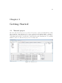
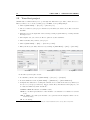
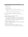


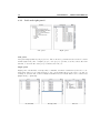
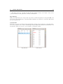

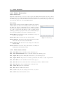

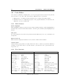

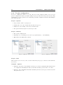

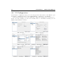
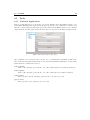

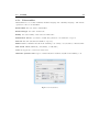
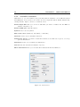

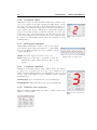
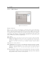
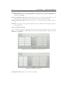


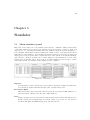

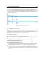
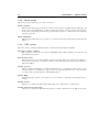

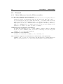
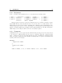


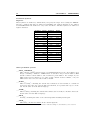


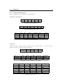


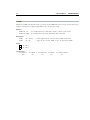
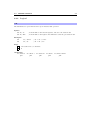

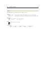
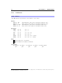


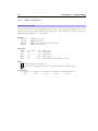
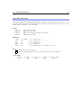

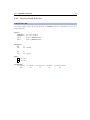
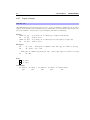
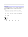
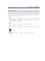

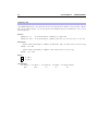
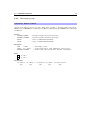
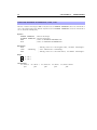
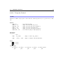
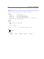


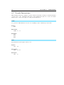
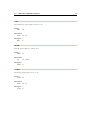


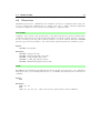


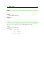
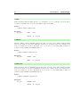
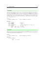
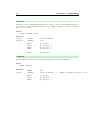
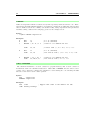
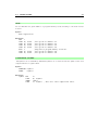


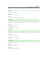


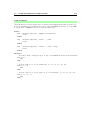


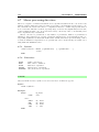


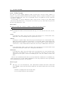

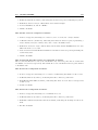
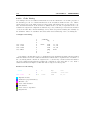


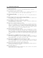
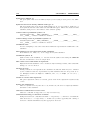
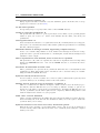

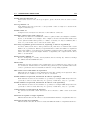


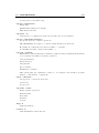
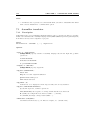
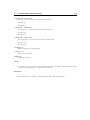

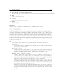
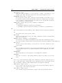
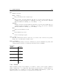

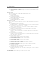
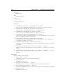


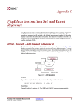


![2008 [DAMN SMALL NAS]](http://vs1.manualzilla.com/store/data/005757702_2-ad0d2f1082977ee9ed587e807bbc0127-150x150.png)