1
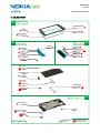
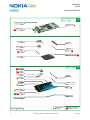
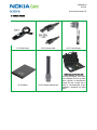
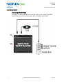
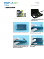
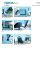
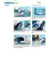
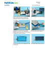
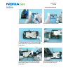
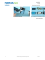
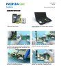
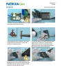
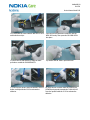
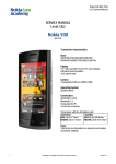
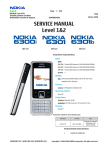
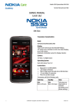
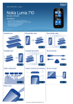
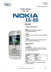
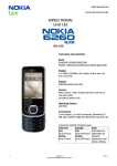
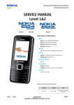
Nokia N8-00 RM-596 Service Manual Level 1&2 SERVICE MANUAL Level 1&2 RM-596 Transceiver characteristics Band WCDMA HSPA 850/900/1700/1900/2100 EGSM 850/900/1800/1900 Display 3.5” AMOLED, up to 16.7 million colors, 16:9 widescreen aspect ratio, 640x360 pixel resolution Camera 12 Mpix Carl Zeiss autofocus camera with CMOS sensor, Xenon flash, 1280x720 25 fps HD video recording Operating System Symbian^3 Connections: HDMI connector with Dolby Digital 5.1 audio, analog TV out with stereo audio via 3.5 mm AV connector, Micro USB 2.0 with OTG support, Bluetooth 3.0, WLAN 802.11 b/g/n Transceiver with BL-4D battery pack Talk time Standby GSM: Up to 12 hours WCDMA: Up to 5.8 hours GSM: Up to 390 hours WCDMA: Up to 400 hours Note: Talk times are dependent on network parameters and phone settings Nokia N8-00 RM-596 Service Manual Level 1&2 Table of contents 1. COPYRIGHT ...............................................................................................................................................................................4 2. WARNINGS AND CAUTIONS .................................................................................................................................................5 2.1 WARNINGS .....................................................................................................................................................................5 2.2 CAUTIONS .......................................................................................................................................................................5 3. ESD PROTECTION ....................................................................................................................................................................6 4. CARE AND MAINTENANCE ....................................................................................................................................................7 5. BATTERY INFORMATION .......................................................................................................................................................8 6. EXPLODED VIEW .....................................................................................................................................................................9 7. SERVICE DEVICES .....................................................................................................................................................................11 8. SOFTWARE UPDATE ...............................................................................................................................................................12 9. DISASSEMBLY INSTRUCTIONS .............................................................................................................................................13 10. ASSEMBLY INSTRUCTIONS....................................................................................................................................................23 11. SOLDER COMPONENTS ..........................................................................................................................................................32 2 Confidential | Copyright © 2010 Nokia | All rights reserved Version 1.0 Nokia N8-00 RM-596 Service Manual Level 1&2 CHANGE HISTORY Status Version No. Date Comments Approved 1.0 28.6.2010 First approved version The purpose of this document is to help NOKIA service levels 1 and 2 workshop technicians to carry out service to NOKIA products. This Service Manual is to be used only by authorized NOKIA service suppliers, and the content of it is confidential. Please note that NOKIA provides also other guidance documents (e.g. Service Bulletins) for service suppliers, follow these regularly and comply with the given instructions. While every endeavor has been made to ensure the accuracy of this document, some errors may exist. If you find any errors or if you have further suggestions, please notify NOKIA using the address below: Nokia Care Academy [email protected] Please keep in mind also that this documentation is continuously being updated and modified, so watch always out for the newest version. 3 Confidential | Copyright © 2010 Nokia | All rights reserved Version 1.0 Nokia N8-00 RM-596 Service Manual Level 1&2 1. COPYRIGHT Copyright © 2010 Nokia. All rights reserved. Reproduction, transfer, distribution or storage of part or all of the contents in this document in any form without the prior written permission of Nokia is prohibited. Nokia, Nokia Connecting People, and Nokia X and Y are trademarks or registered trademarks of Nokia Corporation. Other product and company names mentioned herein may be trademarks or tradenames of their respective owners. Nokia operates a policy of continuous development. Nokia reserves the right to make changes and improvements to any of the products described in this document without prior notice. Under no circumstances shall Nokia be responsible for any loss of data or income or any special, incidental, consequential or indirect damages howsoever caused. The contents of this document are provided “as is”. Except as required by applicable law, no warranties of any kind, either express or implied, including, but not limited to, the implied warranties of merchantability and fitness for a particular purpose, are made in relation to the accuracy, reliability or contents of this document. Nokia reserves the right to revise this document or withdraw it at any time without prior notice. The availability of particular products may vary by region. IMPORTANT This document is intended for use by qualified service personnel only. 4 Confidential | Copyright © 2010 Nokia | All rights reserved Version 1.0 Nokia N8-00 RM-596 Service Manual Level 1&2 2. WARNINGS AND CAUTIONS Please refer to the phone’s user guide for instructions relating to operation, care and maintenance including important safety information. Note also the following: 2.1 Warnings 1. CARE MUST BE TAKEN ON INSTALLATION IN VEHICLES FITTED WITH ELECTRONIC ENGINE MANAGEMENT SYSTEMS AND ANTI–SKID BRAKING SYSTEMS. UNDER CERTAIN FAULT CONDITIONS, EMITTED RF ENERGY CAN AFFECT THEIR OPERATION. IF NECESSARY, CONSULT THE VEHICLE DEALER/MANUFACTURER TO DETERMINE THE IMMUNITY OF VEHICLE ELECTRONIC SYSTEMS TO RF ENERGY. 2. THE HANDPORTABLE TELEPHONE MUST NOT BE OPERATED IN AREAS LIKELY TO CONTAIN POTENTIALLY EXPLOSIVE ATMOSPHERES, EG PETROL STATIONS (SERVICE STATIONS), BLASTING AREAS ETC. 3. OPERATION OF ANY RADIO TRANSMITTING EQUIPMENT, INCLUDING CELLULAR TELEPHONES, MAY INTERFERE WITH THE FUNCTIONALITY OF INADEQUATELY PROTECTED MEDICAL DEVICES. CONSULT A PHYSICIAN OR THE MANUFACTURER OF THE MEDICAL DEVICE IF YOU HAVE ANY QUESTIONS. OTHER ELECTRONIC EQUIPMENT MAY ALSO BE SUBJECT TO INTERFERENCE. 2.2 Cautions 1. Servicing and alignment must be undertaken by qualified personnel only. 2. Ensure all work is carried out at an anti–static workstation and that an anti–static wrist strap is worn. 3. Use only approved components as specified in the parts list. 4. Ensure all components, modules screws and insulators are correctly re–fitted after servicing and alignment. 5. Ensure all cables and wires are repositioned correctly 5 Confidential | Copyright © 2010 Nokia | All rights reserved Version 1.0 Nokia N8-00 RM-596 Service Manual Level 1&2 3. ESD PROTECTION Nokia requires that service points have sufficient ESD protection (against static electricity) when servicing the phone. Any product of which the covers are removed must be handled with ESD protection. The SIM card can be replaced without ESD protection if the product is otherwise ready for use. To replace the covers ESD protection must be applied. All electronic parts of the product are susceptible to ESD. Resistors, too, can be damaged by static electricity discharge. All ESD sensitive parts must be packed in metallized protective bags during shipping and handling outside any ESD Protected Area (EPA). Every repair action involving opening the product or handling the product components must be done under ESD protection. ESD protected spare part packages MUST NOT be opened/closed out of an ESD Protected Area. For more information and local requirements about ESD protection and ESD Protected Area, contact your local Nokia After Market Services representative. 6 Confidential | Copyright © 2010 Nokia | All rights reserved Version 1.0 Nokia N8-00 RM-596 Service Manual Level 1&2 4. CARE AND MAINTENANCE This product is of superior design and craftsmanship and should be treated with care. The suggestions below will help you to fulfil any warranty obligations and to enjoy this product for many years. Keep the phone and all its parts and accessories out of the reach of small children. Keep the phone dry. Precipitation, humidity and all types of liquids or moisture can contain minerals that will corrode electronic circuits. Do not use or store the phone in dusty, dirty areas. Its moving parts can be damaged. Do not store the phone in hot areas. High temperatures can shorten the life of electronic devices, damage batteries, and warp or melt certain plastics. Do not store the phone in cold areas. When it warms up (to its normal temperature), moisture can form inside, which may damage electronic circuit boards. Do not drop, knock or shake the phone. Rough handling can break internal circuit boards. Do not use harsh chemicals, cleaning solvents, or strong detergents to clean the phone. Do not paint the phone. Paint can clog the moving parts and prevent proper operation. Use only the supplied or an approved replacement antenna. Unauthorised antennas, modifications or attachments could damage the phone and may violate regulations governing radio devices. All of the above suggestions apply equally to the product, battery, charger or any accessory. 7 Confidential | Copyright © 2010 Nokia | All rights reserved Version 1.0 Nokia N8-00 RM-596 Service Manual Level 1&2 5. BATTERY INFORMATION Note: A new battery’s full performance is achieved only after two or three complete charge and discharge cycles! The battery can be charged and discharged hundreds of times but it will eventually wear out. When the operating time (talk-time and standby time) is noticeably shorter than normal, it is time to buy a new battery. Use only batteries approved by the phone manufacturer and recharge the battery only with the chargers approved by the manufacturer. Unplug the charger when not in use. Do not leave the battery connected to a charger for longer than a week, since overcharging may shorten its lifetime. If left unused a fully charged battery will discharge itself over time Temperature extremes can affect the ability of your battery to charge. For good operation times with Ni-Cd/NiMh batteries, discharge the battery from time to time by leaving the product switched on until it turns itself off (or by using the battery discharge facility of any approved accessory available for the product). Do not attempt to discharge the battery by any other means Use the battery only for its intended purpose. Never use any charger or battery which is damaged. Do not short-circuit the battery. Accidental short-circuiting can occur when a metallic object (coin, clip or pen) causes direct connection of the + and - terminals of the battery (metal strips on the battery) for example when you carry a spare battery in your pocket or purse. Shortcircuiting the terminals may damage the battery or the connecting object. Leaving the battery in hot or cold places, such as in a closed car in summer or winter conditions, will reduce the capacity and lifetime of the battery. Always try to keep the battery between 15°C and 25°C (59°F and 77°F). A phone with a hot or cold battery may temporarily not work, even when the battery is fully charged. Batteries’ performance is particularly limited in temperatures well below freezing. Do not dispose batteries in a fire! Dispose of batteries according to local regulations (e.g. recycling). Do not dispose as household waste. 8 Confidential | Copyright © 2010 Nokia | All rights reserved Version 1.0 Nokia N8-00 RM-596 Service Manual Level 1&2 6. EXPLODED VIEW A2 WINDOW ASSY (I0008 - I0011) WINDOW FRAME ASSY I0008 WINDOW I0010 TOUCH WINDOW I0009 DISPLAY GASKET I0011 A1 TOP ASSY (I0002 - I0006 POWER KEY I0004 BOTTOM ASSY (I0042 - I0044) TOP COVER I0006 A6 BOTTOM KEY I0042 BOTTOM DECO ASSY I0045 BOTTOM COVER I0044 MAIN ANTENNA I0043 TOP DECO PK I0002 TOP DECO AV I0003 HDMI HATCH I0005 SCREW TORX+ 5 RF 1.2x3.2 I0001 OLED DISPLAY I0012 COMBO ANTENNA I0007 SCREW TORX+ 6 RF 1.4x5.5 I0013 WINDOW FRAME FIXING SPRINGS I0019 FRONT CAMERA BOOT ASSY I0020 ENGINE CHASSIS ASSY (I0015 - I0018) A3 ENGINE CHASSIS I0018 DC JACK I0015 EARPIECE ADHESIVE I0017 EARPIECE I0016 Ver. 1.0 9 Page 1/2 Only available as assembly Confidential | Copyright © 2010 Nokia | All rights reserved These parts can not be reused after removal Version 1.0 Nokia N8-00 RM-596 Service Manual Level 1&2 LIGHT SWAP PACKAGE (I0021 - I0023) PROXY SENSOR BOOT I0046 A4 LIGHT SWAP PWB I0021 PWB SPACER ASSY I0022 FLASH MODULE I0026 BATTERY LID I0041 CAMERA MODULE I0024 SCREW TORX+ 5 M1.4x5.0 I0014 SCREW TORX+ 5 M1.4x5.0 I0025 BATTERY PULL-OUT TAPE I0028 BL-4D BATTERY I0027 BODY ASSY (I0029 - I0040) IHF SPEAKER I0035 A5 IHF GASKET I0036 SIDE SWITCH I0037 CAMERA KEY I0032 FIXING NUT I0038 LOCK KEY I0030 VOLUME KEY I0031 SCREW TORX+ 4 M1.4 I0039 BODY ASSY I0040 CAMERA WINDOW I0029 A4 TYPE LABEL I0023 SIM CARD HATCH I0033 MICRO SD CARD HATCH I0034 Ver. 1.0 10 Page 2/2 Only available as assembly Confidential | Copyright © 2010 Nokia | All rights reserved These parts can not be reused after removal Version 1.0 Nokia N8-00 RM-596 Service Manual Level 1&2 7. SERVICE DEVICES FLS-5 Flash Device BL-4D Battery CA-101 Service Cable SS-182 Camera Removal tool AC-15 Travel Charger Nokia Standard Toolkit (v2) For more information, refer to the Service Bulletin (SB-011) on Nokia Online. Supplier or manufacturer contacts for tool re-order can be found in “Recommended service equipment” document on Nokia Online. Nokia N8-00 RM-596 Service Manual Level 1&2 8. SOFTWARE UPDATE Flash concept (Point of Sale) To use the FLS-5 Flash Dongle, follow the user guide inside the sales package. Please check always for the latest version of flash software, which is available on Nokia Online. 12 Confidential | Copyright © 2010 Nokia | All rights reserved Version 1.0 Nokia N8-00 RM-596 Service Manual Level 1&2 9. DISASSEMBLY INSTRUCTIONS 1) Nokia N8-00 disassembly. 2) You must use the Nokia Standard To 2. You will also need the camera remov 182 and the DC plug. 3) Protect the WINDOW ASSY with protective film. 4) Unscrew the Torx+ size 4 screw 7 full t not remove the screw completely! 5) Unscrew also the second Torx+ size 4 screw on the other side of the phone 7 full turns. Do not remove the screw completely! 6) Pull out the BOTTOM ASSY to the direct and remove it. Nokia N8-00 RM-596 Service Manual Level 1&2 wn end of the BATTERY LID. Release d by pulling it into direction 8) Now the BATTERY LID can be removed. move the BATTERY by using the T TAPE. 10) Open the HDMI HATCH. Torx+ size 5 screw. Do not use it 12) Remove the TOP ASSY by pushing it from the back side to the direction shown. Nokia N8-00 RM-596 Service Manual Level 1&2 13) Pull out and remove the HDMI HATCH. 14) Unscrew the four Torx+ size 5 screws order shown. These screws cannot be use Discard them. 15) Slide SRT-6 to the direction shown to release the clip holding the WINDOW ASSY. 16) Release also the second clip on the ot the phone by sliding the SRT-6 to the dire shown. 17) Carefully lift up the top side of the WINDOW ASSY to gain access to the connectors underneath. Be careful not to damage the connectors while lifting up the WINDOW ASSY! 18) Use the SS-93 to open the WINDOW A CONNECTOR. Be careful not to damage the or components nearby! Nokia N8-00 RM-596 Service Manual Level 1&2 19) Open also the LCD CONNECTOR with the SS-93 by lifting it from the side shown. Be careful not to damage the connector or components nearby! 20) The WINDOW ASSY can now be separa 21) Insert the SS-93 between the LCD and the WINDOW ASSY. Slide the SS-93 to the direction shown to release one side of the LCD. Be careful not to damage the LCD while releasing it! 22) Release also the other side of the LCD SS-93. The LCD can now be removed. 23) Protect the other side of the WINDOW ASSY with protective film. 24) Protect the display with protective fil Nokia N8-00 RM-596 Service Manual Level 1&2 25) Release the COMBO ANTENNA with the SS-93. 26) Remove the COMBO ANTENNA. 27) Unscrew the three Torx+ size 6 screws in the order shown. These screws cannot be used again. Discard them. 28) Lift up and remove the ENGINE CHASS 29) Use tweezers to remove the two WINDOW FRAME FIXING SPRINGS. Do not use them again. Discard them. 30) Remove the EARPIECE GASKET with th Do not use it again. Discard it. Nokia N8-00 RM-596 Service Manual Level 1&2 31) Use the DC plug to lift up the DC JACK. 32) Release the EARPIECE with the SRT-6 a 33) Remove the EARPIECE with the tweezers. The EARPIECE cannot be used again. Discard it. 34) Remove the EARPIECE GASKET with th tool. Be careful not to injure yourself with end of the dental tool! The EARPIECE GASK reusable. Discard it. 35) Remove the FRONT CAMERA BOOT with the tweezers. Do not use it again. Discard it. 36) Lift up the AV JACK carefully as shown releasing the ENGINE BOARD. Nokia N8-00 RM-596 Service Manual Level 1&2 37) To separate the ENGINE BOARD from the BODY ASSY, lift up the shown side (1). Then pull the ENGINE BOARD to the direction shown (2). 38) The ENGINE BOARD can now be separa 39) Open the two clips holding the SUB PWB with the SS-93. 40) Turn over the SUB PWB. Be careful no damage the flex! 41) Use the SS-93 to release the SUB PWB SUPPORT. Be careful not to damage the components nearby! 42) Remove the SUB PWB SUPPORT. Do no again. Nokia N8-00 RM-596 Service Manual Level 1&2 43) To release the CAMERA, push down the camera removal tool SS-182 until camera retaining clips are released. Lift up the SS-182 and remove the CAMERA. 44) Release the IHF SPEAKER with the den and remove it with the tweezers. Do not SPEAKER again. 45) Remove the IHF SPEAKER GASKET with the dental tool. Do not use it again. Discard it. 46) Pull out and remove the SD CARD HAT 47) Remove also the SIM CARD HATCH. 48) Carefully lever out the FLASH MODULE SS-93. Nokia N8-00 RM-596 Service Manual Level 1&2 21 49) Remove the FLASH MODULE with the tweezers. 50) Release the SIDE SWITCH with the denta Remove it with the tweezers. 51) Unscrew the Torx+ size 4 screw to release the FIXING NUT. 52) Remove the screw and the FIXING NUT w tweezers. 53) To release the second FIXING NUT, unscrew the Torx+ size 4 screw. 54) Remove the screw with the tweezers. Confidential | Copyright © 2010 Nokia | All rights reserved Version 1.0 Nokia N8-00 RM-596 Service Manual Level 1&2 55) Remove the FIXING NUT. 56) The Nokia N8-00 disassembly is now co -END OF DISASSEMBLY- 22 Confidential | Copyright © 2010 Nokia | All rights reserved Version 1.0 Nokia N8-00 RM-596 Service Manual Level 1&2 10. ASSEMBLY INSTRUCTIONS 1) Nokia N8-00 assembly. 2) For assembling you need the Nokia Standard Toolkit version 2. 3) When inserting the CAMERA MODULE, check that the shown clip is on the same side as the guiding notch. Press the CAMERA MODULE carefully to attach the camera retaining clips. 4) Place a new SUB PWB SUPPORT to the ENGINE BOARD by using the shown guiding pin. 5) Press the SUB PWB SUPPORT along the edges with the SS-93 to activate the adhesive. 6) Place the SUB PWB on top of the SUB PWB SUPPORT. Be careful not to damage the flex! Nokia N8-00 RM-596 Service Manual Level 1&2 7) Press the SUB PWB carefully with the SS-93. Make sure the two clips shown are locked. 8) Insert the two FIXING NUTS. 9) Note that there are two different TORX+ size 4 screw heads used in this device. The first two screws are countersunk heads. 10) Hold the FIXING NUTS in place with your finger. Tighten the two TORX + size 4 screws until the FIXING NUTS stay in place. Do not tighten them completely! If the screws are tightened too much the BOTTOM COVER cannot be assembled. 11) Place the SIDE SWITCH with the tweezers. Use the dental tool to lever the SIDE SWITCH under the two shown clips. Be careful not to injure yourself with the sharp end of the dental tool! 12) Place the FLASH MODULE with the tweezers. Nokia N8-00 RM-596 Service Manual Level 1&2 13) Push down the FLASH MODULE with the SS-93 to attach the three clips. 14) Insert the SIM CARD HATCH fastener into the BODY ASSY cavity. Then press the SIM CARD HATCH into place. 15) Insert the SD CARD HATCH by using the same procedure as with the SIM CARD HATCH. 16) Remove the IHF GASKET protective film. 17) Place the IHF GASKET with the tweezers. Press it down carefully with the SS-93 to activate the adhesive. 18) Place the IHF SPEAKER. Make sure that the IHF SPEAKER springs point towards the FLASH MODULE. Press the speaker with the SS-93 to activate the adhesive. Nokia N8-00 RM-596 Service Manual Level 1&2 19) Remove the camera lens protective film with the tweezers. 20) To insert the ENGINE BOARD to the BODY ASSY, first insert the side where the USB CONNECTOR is located. 21) Lower down the other side of the ENGINE BOARD. Make sure the LOCK KEY is placed as shown in the small picture. 22) Press the AV CONNECTOR with the SS-93 until it snaps into place. 23) Remove the EARPIECE ADHESIVE protective film. 24) Use the tweezers to place the EARPIECE ADHESIVE. Activate the adhesive by carefully pressing down on it with the SS-93. Remove the blue EARPIECE ADHESIVE protective film. Nokia N8-00 RM-596 Service Manual Level 1&2 25) Remove the new EARPIECE from the protective film. 26) Place the EARPIECE and press it with the SS-93 to activate the adhesive. 27) Insert the DC JACK with the tweezers and firmly press down on it with the SS-93 until it moves into its socket. 28) Place the FRONT CAMERA BOOT ASSY. 29) When placing the two WINDOW FRAME FIXING SPRINGS, press down on the shown places to get the springs correctly in their place. 30) Use the SS-93 to spread the sides of the BODY ASSY and push down the ENGINE CHASSIS ASSY to lock the springs. Nokia N8-00 RM-596 Service Manual Level 1&2 31) Tighten the two TORX + size 6 screws to the torque of 15 Ncm in the order shown. 32) Tighten the TORX + size 6 screw to the torque of 8 Ncm. 33) Push the COMBO ANTENNA into place. 34) Remove the display protective film and lower down the other end of the DISPLAY. Align the DISPLAY to the WINDOW ASSY according to the small edge on the WINDOW ASSY. Press and slide fingers along the sides of the DISPLAY to activate the adhesive. 35) Hold the WINDOW ASSY as shown. Connect the DISPLAY CONNECTOR by pressing down on it carefully with the SS-93. Be careful not to damage the connector or components nearby! 36) Connect the WINDOW ASSY CONNECTOR by carefully pressing it down with the SS-93. Be careful not to damage the connector or components nearby! Nokia N8-00 RM-596 Service Manual Level 1&2 37) Carefully place down the WINDOW ASSY. Make sure that the connectors remain connected! 38) Press the WINDOW ASSY from both sides to get the WINDOW FRAME FIXING SPRINGS locked. 39) Tighten the four TORX + size 4 screws to the torque of 14 Ncm in the order shown. 40) Remove the protective film from the TOP COVER and open the HDMI HATCH. 41) Push the TOP COVER into place and close the HDMI HATCH. Make sure that the TOP COVER is in its place by firmly pressing on both corners of the TOP COVER. 42) Tighten the TORX + size 5 screw to the torque of 11 Ncm. Nokia N8-00 RM-596 Service Manual Level 1&2 43) Close the HDMI HATCH and check that the TOP COVER edges are attached properly. 44) Place the BATTERY PULL-OUT TAPE to the BATTERY as shown. Press it down slightly to activate the adhesive. 45) Insert the BATTERY as shown. 46) Place the shown end of the BATTERY LID and then lower down the other end. Note that the BATTERY PULL-OUT TAPE is left under the BATTERY LID. 47) Remove the protective film of the BOTTOM DECO ASSY. 48) And attach it to the BOTTOM COVER. Nokia N8-00 RM-596 Service Manual Level 1&2 49) Press and hold both of the two shown screws in. 50) Then place the BOTTOM COVER as shown and press it into its place. If the BOTTOM COVER does not go in properly, loosen up the side screws a bit. 51) Hold the BOTTOM COVER in its place and tighten the TORX + size 4 screws to the torque of 21 Ncm on both sides. 52) Nokia N8-00 assembly is now complete. -END OF ASSEMBLY- Nokia N8-00 RM-596 Service Manual Level 1&2 11. SOLDER COMPONENTS TOP S2401 S2402 S2400 F3350 X7402 V2422 S2403 V2420 G2200 F3300 V2411 V2410 BOTTOM X2500 X3300 X1650 X6700 X7403 X6702 X7404 Ver. 1.0 32 Confidential | Copyright © 2010 Nokia | All rights reserved Version 1.0