1
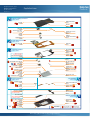
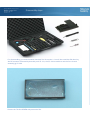
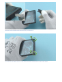
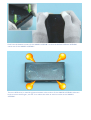
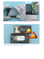
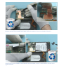
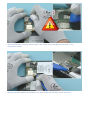
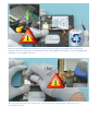
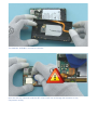
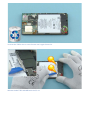
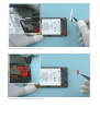
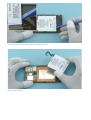
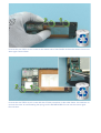
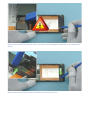
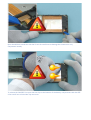
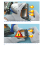
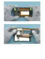
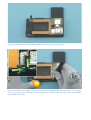
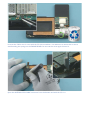
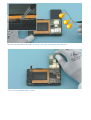
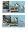
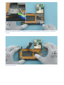
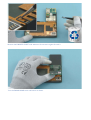
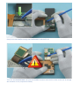
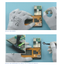
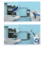
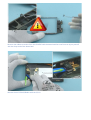
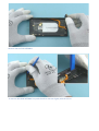
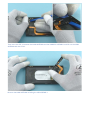
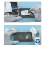
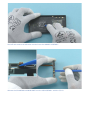
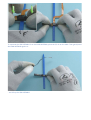
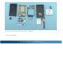
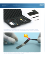
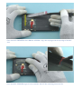
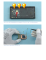
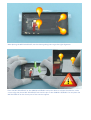
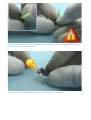
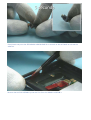
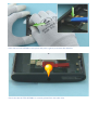
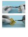
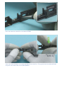
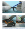
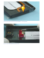
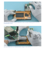
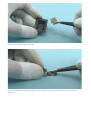
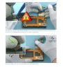
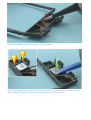
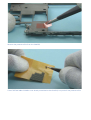
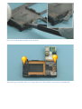
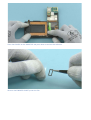
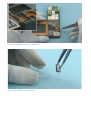
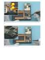
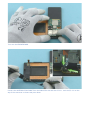
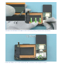
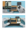
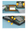
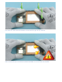
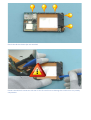
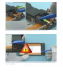
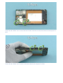
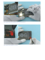
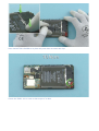
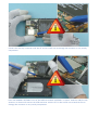
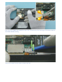
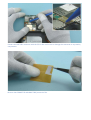
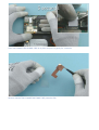
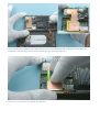
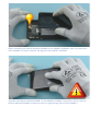
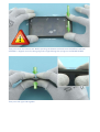
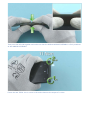
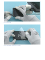
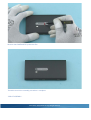
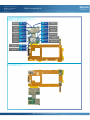
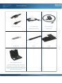
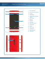
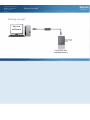
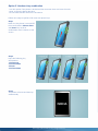
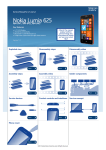
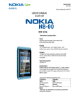
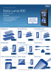
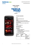
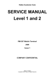
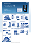
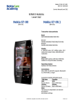
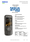
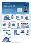
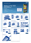
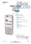
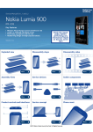
Service Manual for L1 and L2
Nokia Lumia 920
RM-820, RM-821
Key features
z
z
z
z
z
z
Windows Phone 8
1.5 GHz dual-core processor (Qualcomm Snapdragon S4)
32 GB internal flash memory
EGSM, WCDMA HSPA and 4G LTE
Near Field Communication (NFC) technology
Wireless charging (Qi standard)
Check the repair
policy before
performing any
mechanical repair
on Service Level
1&2!
Version 1.0
Exploded view
Disassembly steps
More
Disassembly video
More
Assembly video
Assembly steps
More
Solder components
More
Service devices
More
Product controls and interfaces
More
More
Phone reset
More
©2012 Nokia | Nokia Internal Use only | All Rights Reserved.
Service concept
More
Service Manual Level 1 and 2
Exploded view
Nokia Lumia 920
RM-820, RM-821
Version 1.0
DISPLAY MODULE ASSEMBLY
(I0003 - I0005)
WINDOW ASSEMBLY
I0003
A-COVER
I0005
DISPLAY
I0004
SIM DOOR
I0001
SCREW TORX+ SIZE 4
M1.4 x 3.0
I0016
CAMERA
I0019
SCREW TORX+ SIZE 5
M2.5 X 9.7
I0002
CAMERA
CONNECTOR SUPPORT
I0020
CAMERA BOOT
I0018
2
LIGHT SWAP PACKAGE
3
CHASSIS ASSEMBLY
(I0006 - I0008)
LIGHT SWAP PWB
I0006
MAIN FLEX
I0007
IHF SPEAKER
I0024
SPEAKER GASKET
I0025
CHASSIS
I0026
(I0023 - I0026)
* Will be part of the
A3 CHASSIS ASSEMBLY
EJECTING ARM CUSHION
I0023
EARPIECE
I0021
EARPIECE GASKET
I0022
BATTERY SUPPORT
I0013
BATTERY HOLDER
I0012
USB CONNECTOR SUPPORT
I0011
TYPE LABEL
I0008
TYPE LABEL SUPPORT
I0017
SCREW TORX+
SIZE 2 MG1.2 x 2.6
I0015
CONNECTOR
HOLDING TAPE
I0010
BATTERY
CONNECTOR FIXING TAPE
I0009
6
SCREW TORX+
SIZE 4 M1.4 X 3.0
I0016
ANTENNA COAX CABLE
I0027
BATTERY BP-4GW
I0014
AV FLEX ASSEMBLY
USB ASSEMBLY
(I0040 - I0042)
(I0035 - I0036)
2ND MICROPHONE
I0041
MICRO USB CONNECTOR
I0035
MICROPHONE
I0036
AV JACK
I0042
AV FRAME
I0040
MAIN ANTENNA
I0037
WPC RX MODULE
I0039
USB FLEX SUPPORT
I0038
* Will be part of the
I0037 MAIN ANTENNA
UNIBODY ASSEMBLY
HEAT SPREADER
* Will be part of the I0028
A4 UNIBODY ASSEMBLY
v1.0
AV DECO ADHESIVE
I0031
VOLUME KEY
I0029
LED FLASH
I0032
CAMERA DECO
I0033
5
(I0028 - I0034)
CAPTURE KEY
I0030
4
CAMERA WINDOW
I0034
Only available
as assembly
©2012 Nokia | Nokia Internal Use only | All Rights Reserved.
Not reuseable
after removal
Repair/swap
only in level 3
Service Manual Level 1 and 2
Nokia Lumia 920
RM-820, RM-821
Version 1.0
Disassembly steps
For disassembling you need the Nokia Standard Tool kit version 2. You will also need the SIM door key,
the RF connector disassembly/assembly tool SS-231, the SS-299 screwdriver and the Care chassis
assembly jig SS-289.
Protect the TOUCH SCREEN with protective film.
Release the SIM DOOR with the SIM door key and remove it.
Unscrew the two TORX+ size 5 screws from the bottom of the device in the order shown.
Push from the bottom corners of the UNIBODY ASSEMBLY so that the DISPLAY MODULE ASSEMBLY
comes out of the UNIBODY ASSEMBLY.
There are differecies in material tightness between color variants. If the UNIBODY ASSEMBLY sides are
hard to remove with fingers, use SRT-6 to release the sides to avoid scratches in the UNIBODY
ASSEMBLY.
Lift the DISPLAY MODULE ASSEMBLY out of the UNIBODY ASSEMBLY bottom end first.
Turn the DISPLAY MODULE ASSEMBLY so that the ENGINE BOARD side is facing up and place it next to the
UNIBODY ASSEMBLY. Be careful not to bend the USB flex.
Remove the BATTERY CONNECTOR FIXING TAPE with tweezers. Do not use it again. Discard it.
If the device has the CONNECTOR HOLDING TAPE assembled, remove it with tweezers. Do not use it
again. Discard it.
Open the BATTERY connector with the SRT-6. Be careful not to damage the connector or any
components nearby.
Release the USB CONNECTOR SUPPORT from the left side with the sharp end of the SS-93.
Remove the USB CONNECTOR SUPPORT by lifting it up with tweezers. Be careful not to insert the
tweezers under the connectors located beneath the USB CONNECTOR SUPPORT. The USB CONNECTOR
SUPPORT is not reusable. Discard it.
Open the USB flex connector with the SRT-6. Be careful not to damage the connector or any
components nearby.
The UNIBODY ASSEMBLY can now be removed.
Open the side key connector with the SRT-6. Be careful not to damage the connector or any
components nearby.
Unscrew the TORX+ size 4 screw. Do not use it again. Discard it.
Release the BATTERY HOLDER with the SS-93.
Remove the BATTERY HOLDER with tweezers.
Remove the BATTERY SUPPORT with tweezers.
Lift up the BATTERY from the bottom end with the SS-93.
Remove the BATTERY.
Unscrew the two TORX+ size 4 screws on the shown side of the CHASSIS in the order shown. Do not use
them again. Discard them.
Unscrew the two TORX+ size 2 screws with the SS-299 screwdriver in the order shown. Use tweezers to
remove the screw to avoid bending the springs on the ENGINE BOARD. Do not use the screws again.
Discard them.
Open the touch connector with the SS-93. Be careful not to damage the connector or any components
nearby.
Slide the touch connector out of the CHASSIS as shown with the SS-93.
Open the DISPLAY connector with the SS-93. Be careful not to damage the connector or any
components nearby.
To release the CHASSIS first open the two clips at the bottom of the battery compartment with the SRT6. Be careful not to bend the clips too much.
Then release the clips from the shown side of the CHASSIS starting from the top.
Then open the two clips at the bottom end starting from the shown side. Be careful not to break the
clips.
Lift up the CHASSIS including the ENGINE BOARD from the shown side.
Remove the CHASSIS including the ENGINE BOARD.
Place the CHASSIS including the ENGINE BOARD on the Care chassis assembly jig.
Open the ANTENNA COAX CABLE connector from the main ENGINE BOARD side with the SS-231. Lock the
SS-231 to the top of the connector as shown and lift it up carefully. Keep the other end of the ANTENNA
COAX CABLE connected.
Unscrew the TORX+ size 2 screw with the SS-299 screwdriver. Use tweezers to remove the screw to
avoid bending the springs on the ENGINE BOARD. Do not use the screw again. Discard it.
Open the ANTENNA COAX CABLE connector from the bottom end with the SS-231.
Remove the ANTENNA COAX CABLE by lifting it from the metal sheets with tweezers.
Turn over the ENGINE BOARD as shown.
Remove the TYPE LABEL SUPPORT with tweezers.
Remove the EARPIECE with tweezers.
Release the adhesive holding the CHASSIS and the MAIN FLEX together by sliding the SS-93 under the
CHASSIS.
Remove the CHASSIS.
Remove the EARPIECE GASKET with tweezers. Do not use it again. Discard it.
Turn the ENGINE BOARD over and hold it as shown.
Gently PUSH the CAMERA through the CAMERA BOOT with the SS-93.
Turn over the ENGINE BOARD and open the CAMERA connector with the SS-93. Be careful not to damage
the connector or any components nearby.
Remove the CAMERA.
Remove the CAMERA BOOT by sliding it out as shown with tweezers.
Release the IHF SPEAKER with the sharp end of the SS-93.
Remove the IHF SPEAKER with tweezers. Do not use it again. Discard it.
Remove the adhesive remains from the CHASSIS with the dental tool. Be careful not to injure yourself
with the sharp end of the dental tool.
Release the AV FLEX ASSEMBLY with the SS-93.
Remove the AV FLEX ASSEMBLY.
To remove the MAIN ANTENNA first push the other side out slightly with the SS-93.
Then insert the SRT-6 between the MAIN ANTENNA and the UNIBODY ASSEMBLY and lift out the MAIN
ANTENNA with the SS-93.
Remove the MAIN ANTENNA including the USB ASSEMBLY.
Release the WPC RX MODULE from the UNIBODY ASSEMBLY with the SS-93.
Remove the WPC RX MODULE. Do not use it again. Discard it.
Peel off and remove the adhesive remains from the UNIBODY ASSEMBLY.
Release the SECONDARY MICROPHONE from the USB ASSEMBLY with the SS-93.
To separate the USB ASSEMBLY from the MAIN ANTENNA, place the SS-93 on the table. Then gently bend
the MAIN ANTENNA against it...
...and lift up the USB ASSEMBLY
The Nokia Lumia 920 disassembly procedure is complete.
-END OF DISASSEMBLY-
©2012 Nokia | Nokia Internal Use only | All Rights Reserved.
Service Manual Level 1 and 2
Nokia Lumia 920
RM-820, RM-821
Version 1.0
Assembly steps
For assembling you need the Nokia Standard Tool kit version 2. You will also need the RF connector
disassembly/assembly tool SS-231, the Care chassis assembly jig SS-289 and the SS-299 screwdriver.
If the HEAT SPREADER is not already assembled to the UNIBODY ASSEMBLY, first peel off the protective
film. Leave the other part of the protective film attached.
Place the HEAT SPREADER to the UNIBODY ASSEMBLY. Align the top edge with the top edge of the NFC
area.
Press the HEAT SPREADER to get it firmly attached. Peel off the remaining protective film.
Make sure the HEAT SPREADER does not overlap the NFC area and there is a small gap between.
Remove the WPC RX MODULE protective film.
When placing the WPC RX MODULE, use the shown guiding lines to get the right alignment.
Place the WPC RX MODULE to the UNIBODY ASSEMBLY and press down to activate the adhesive. Make
sure to align the shown WPC RX MODULE hole and the pin on the UNIBODY ASSEMBLY. Do not place the
WPC RX MODULE on the shown part of the camera support!
Place the AV FLEX ASSEMBLY to the AV FRAME top end first and press down the bottom end. Be careful
not to damage the AV FLEX ASSEMBLY!
Make sure the SECONDARY MICROPHONE goes under the edge of the AV FRAME.
Gently bend and press the SECONDARY MICROPHONE for 5 seconds to the AV FRAME to activate the
adhesive.
Remove the AV FLEX ASSEMBLY protectve film from the UNIBODY ASSEMBLY.
Place the AV FLEX ASSEMBLY to its place and press it gently to activate the adhesive.
Check that the AV FLEX ASSEMBLY is correctly placed from the other side.
Remove the protective film from the MAIN ANTENNA.
If the USB FLEX SUPPORT is not already assembled to the MAIN ANTENNA, first peel off the protective
film.
Place the USB FLEX SUPPORT to the MAIN ANTENNA.
Attach the USB ASSEMBLY to the MAIN ANTENNA shown side first. Then gently bend the MAIN ANTENNA
and push in the other side of the USB ASSEMBLY.
Attach the MICROPHONE to the MAIN ANTENNA with the SS-93.
Place the MAIN ANTENNA including the USB ASSEMBLY to the UNIBODY ASSEMBLY shown side first. Then
push in the other side of the MAIN ANTENNA. Press the MAIN ANTENNA for 5 seconds with slight force to
activate the adhesive.
Check from the other side that the USB ASSEMBLY is correctly placed.
Remove the CAMERA WINDOW protective film.
Place the ENGINE BOARD including the MAIN FLEX on the Care chassis assembly jig and turn over the
ENGINE BOARD as shown.
Place the CAMERA BOOT to the ENGINE BOARD by sliding it in from the side.
Remove the CAMERA from its packing.
Place the CAMERA CONNECTOR SUPPORT to the CAMERA flex and press down gently to activate the
adhesive.
Assemble the CAMERA to the ENGINE BOARD by first connecting the CAMERA connector with the SS-93.
Be careful not to damage the connector or any nearby components.
Bend the CAMERA flex and push the CAMERA into the CAMERA BOOT.
Remove the SPEAKER GASKET protective film from the CHASSIS.
Place the IHF SPEAKER to the CHASSIS and press down gently to activate the adhesive. Make sure that
the IHF SPEKAER is aligned correctly and the shown pins are facing the right way.
Remove the protective film from the CHASSIS.
If the EJECTING ARM CUSHION is not already assembled to the CHASSIS, first peel off the protective film.
Place the EJECTING ARM CUSHION to the CHASSIS.
When placing the CHASSIS make sure to align the pins of the CHASSIS to the holes in the MAIN FLEX.
Place the CHASSIS on the MAIN FLEX and press down to activate the adhesive.
Remove the EARPIECE GASKET protective film.
Place the EARPIECE GASKET to the MAIN FLEX.
Remove the EARPIECE from its packing.
Place the EARPIECE to its place. Make sure it is aligned correctly and the shown pins are facing the right
way.
Place the TYPE LABEL SUPPORT to its place.
Turn over the ENGINE BOARD.
Connect the ANTENNA COAX CABLE from the MAIN FLEX side with the SS-231. Lock the SS-231 to the
top of the connector as shown and press down.
Assemble the ANTENNA COAX CABLE to the CHASSIS by pushing it between the metal sheets.
Fasten the TORX+ size 2 screw with the SS-299 screwdriver to the torque of 10 Ncm.
Connect the other end of the ANTENNA COAX CABLE to the ENGINE BOARD with the SS-231.
The ENGINE BOARD including the CHASSIS can now be removed from the Care chassis assembly jig.
Assemble the ENGINE BOARD including the CHASSIS to the DISPLAY MODULE ASSEMBLY shown side first.
Use the shown screw holes to get the right alignment.
Make sure that the front camera and the microphone are aligned correctly.
Press down the other side and the bottom of the CHASSIS to get the clips attached.
Make sure that the clips on the DISPLAY MODULE ASSEMBLY are not left under the CHASSIS!
Check that all the shown clips are attached.
Connect the DISPLAY connector with the SS-93. Be careful not to damage the connector or any nearby
components.
Bend the TOUCH SCREEN connector as shown and slide it into the notch on the CHASSIS.
Connect the TOUCH SCREEN connector with the SS-93. Be careful not to damage the connector or any
nearby components.
Fasten the two TORX+ size 2 screws with the SS-299 screwdriver in the order shown to the torque of 10
Ncm.
Fasten the two TORX+ size 4 screws in the order shown to the torque of 10 Ncm.
Place the BATTERY to the BATTERY compartment top end first.
Place the BATTERY SUPPORT to its place.
Place the BATTERY HOLDER to its place and press down to attach the clips.
Fasten the TORX+ size 4 screw to the torque of 10 Ncm.
Connect the side key connector with the SS-93. Be careful not to damage the connector or any nearby
components.
Place the UNIBODY ASSEMBLY next to the DISPLAY MODULE ASSEMBLY as shown. Hold the USB flex with
tweezers as shown and connect the USB connector with the SS-93. Be careful not to bend the flex or
damage the connector or any nearby components.
Place the USB CONNECTOR SUPPORT on top of the connectors by first inserting it to the shown holes on
the ENGINE BOARD shielding.
Then press it down from the sides to attach the clips.
Connect the BATTERY connector with the SS-93. Be careful not to damage the connector or any nearby
components.
Remove the CONNECTOR HOLDING TAPE protective film.
Place the CONNECTOR HOLDING TAPE to its place and press it gently for 5 seconds.
Remove the BATTERY CONNECTOR FIXING TAPE protective film.
Place the BATTERY CONNECTOR FIXING TAPE on top of the ENGINE BOARD shieldings and the BATTERY
connector. Use the edges of the shown shielding to get the right alignment.
Press for 5-10 seconds to activate the adhesive.
Before assembling the DISPLAY MODULE ASSEMBLY to the UNIBODY ASSEMBLY make sure that the AV
FLEX ASSEMBLY is properly attached and aligned to the UNIBODY ASSEMBLY.
Assemble the DISPLAY MODULE ASSEMBLY to the UNIBODY ASSEMBLY top end first. Do not slide the
DISPLAY MODULE ASSEMBLY towards top end as it might damage the AV FLEX ASSEMBLY!
Then press down the bottom end. Before pressing the bottom end make sure the DISPLAY MODULE
ASSEMBLY is aligned correctly! Wrong alignment might damage the springs on the ENGINE BOARD!
Then press the right side together.
Then press the left side together and make sure that the DISPLAY MODULE ASSEMBLY is firmly attached
to the UNIBODY ASSEMBLY.
Fasten the two TORX+ size 5 screws in the order shown to the torque of 11 Ncm.
Insert the SIM DOOR.
Remove the UNIBODY ASSEMBLY protective film.
Remove the CAMERA DECO protective film.
The Nokia Lumia 920 assembly procedure is complete.
-END OF ASSEMBLY-
©2012 Nokia | Nokia Internal Use only | All Rights Reserved.
Service Manual Level 1 and 2
Nokia Lumia 920
RM-820, RM-821
Version 1.0
HB Div ant
GND spring
Solder components
X7708
X6301
HB Div ant
spring
BT/WLAN Ant
GND spring
NFC Ant
spring
X1470
NFC Ant
spring
AV
connector
BT/WLAN Ant
spring
LED Flash
spring
LED Flash
GND spring
Wireless charging
spring
X2100
GNSS Ant
spring
X1103
Wireless charging
spring
X1101
Wireless charging
spring
X1100
Wireless charging
GND spring
BOTTOM
©2012 Nokia | Confidential | All Rights Reserved.
Service Manual Level 1 and 2
Nokia Lumia 920
RM-820, RM-821
Version 1.0
Service devices
CA-101 Service cable
SIM Door key
AC-16 USB Charger
AC-50 USB Charger
(ROW and HSPA Variants)
(AT&T Variant)
SS-231
SS-289
Nokia Standard Toolkit (v2)
For more information, refer to the Service
Bulletin (SB-011) on Nokia Online. Supplier or
manufacturer contacts for tool re-order can be
found in “Recommended service equipment”
document on Nokia Online.
©2012 Nokia | Nokia Internal Use only | All Rights Reserved.
Service Manual Level 1 and 2
Product controls and interfaces
Nokia Lumia 920
RM-820, RM-821
Version 1.0
1
2
1 — Micro SIM holder
2 — Nokia AV 3.5 mm connector
3
4
5
3 — Earpiece
4 — Front camera
5 — Ambient light & Proximity
sensors
6 — Touch screen
6
7 — Back key
8 — Start key
9 — Search key
10 — Micro USB connector
8
9
7
11 — Loudspeaker
12 — Camera
13 — Camera flash
14 — Volume keys
10
15 — Power/Lock Key
16 — Camera key
11
12
13
14
15
16
©2012 Nokia | Nokia Internal Use only | All Rights Reserved.
Service Manual Level 1 and 2
Nokia Lumia 920
RM-820, RM-821
Version 1.0
Service concept
Flashing concept
Service
software
CA-101
Note: Charged
battery is mandatory
Transceiver with
embedded battery
©2012 Nokia | Nokia Internal Use only | All Rights Reserved.
Service Manual Level 1 and 2
Nokia Lumia 920
RM-820, RM-821
Version 1.0
Phone reset
Hardware reset
If the phone hardware is jammed, you should first recommend that
the consumer performs a hardware reset. The hardware reset does
not reset the Windows Live ID or remove any consumer data. Because
the consumer cannot remove the battery to reset the phone the
phone has a special electronic circuit which cuts the phone power
when the volume down and power keys are pressed for 5 seconds.
To perform the hardware reset press the Volume down and Power
keys and hold them for 5 seconds. The phone screen will turn black
(phone is off). Then press the Power key to turn on the phone.
Software / operating system (OS) reset
The software / operating system (OS) reset returns the phone to its out-of-the-box state. Note that this
procedure erases all consumer data! Always first try to perform a hardware reset.
Option 1: About menu
- Use this option if the consumer knows the lock code
- This option warns the consumer about data loss!
- Tap Settings > About > reset your phone
Option 2: Hardware key combination
- Use this option if the phone is locked and the consumer does not know the code
- Note: no warning about data loss!
- Do not advertise this feature to consumers!
Follow next steps to perform OS reset with phone keys.
Step 1
Make sure the phone is turned Off.
Press and hold the Volume down
and Power keys until an
exclamation mark is shown on the
screen
Step 2
Input the following key
combination:
1. Volume up
2. Volume down
3. Power
4. Volume down
Step 3
The phone will reset and boot up
automatically
©2012 Nokia | Nokia Internal Use only | All Rights Reserved.
Service Manual Level 1 and 2
Version history
Nokia Lumia 920
RM-820, RM-821
Version 1.0
Version
Date
Description
1.0
11.10.2012
First published version
©2012 Nokia | Nokia Internal Use only | All Rights Reserved.