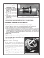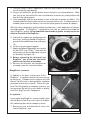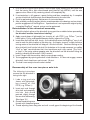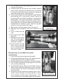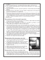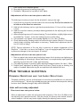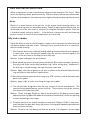
1
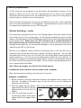
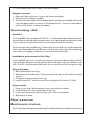
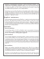
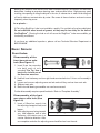
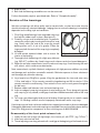
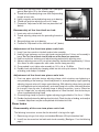
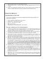
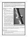
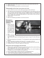
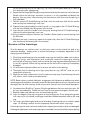
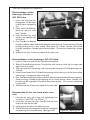
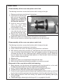
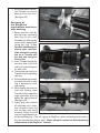
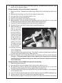
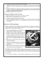
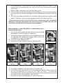
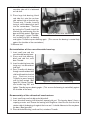
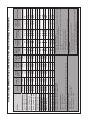
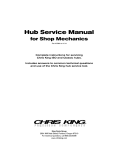
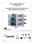
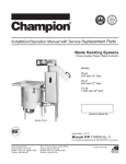
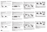
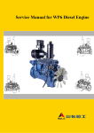
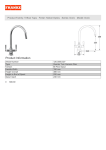
Hub Service Manual
for Shop Mechanics
rev. 12/12
Complete instructions for servicing
Chris King ISO and Classic hubs.
Includes answers to common technical questions
and use of the Chris King hub service tool.
King Cycle Group
2801 NW Nela Street; Portland, Oregon 97210
For technical questions, call 800.523.6008
www.chrisking.com
HUBSETS
This manual is intended for the mechanic who already possesses a familiarity with hubset
adjustment techniques and who are interested in the learing how to completely overhaul their
Chris King Classic or ISO hubsets.
Features
• Classic, High Flange, ISO Disc, single speed, and tandem hubs available
• Exclusive patented RingDrive™ engagement system offers 72 points of instant and positive
engagement and extremly high torque carrying capacity ideal for hard racing, tandems,
etc.
• Bearings are fully serviceable and are available in either steel or ceramic options
• Strong and stiff 19.5mm axles
• In-house design and manufacturing - 100% made by Chris King in the USA
• Unparalleled quality and reliability
• Responsibly lightweight
Set-up
Getting Started
and
Cautions
The following issues that are important to review before servicing and/or trouble shooting your
Chris King hub:
Adjust the preload on the bearings directly after building the
wheel
Spoke tension pulling out on the flanges can slightly loosen the preload adjustment on the
bearings. The hub(s) come pre-adjusted from the factory anticipating both spoke tension and
skewer compression. However, because of variations in wheel-building practices, a minor
adjustment should always be performed upon completion of the wheel build. Please see the
appropriate “adjustment” section and check the hub before using.
Chris King hubs feature adjustable bearing preload
The bearings should be kept in proper adjustment for optimum product performance. Do not
allow the adjustment to become loose, as this may cause a loss of performance that could
lead to damage to the hubs.
2
Rev. 12/12-A
Use steel quick releases for maximum rigidity
Our 19.5mm axle is one of the stiffest available. However, performance will be maximized with
the stiffest possible attachment to the frame or fork. Some Chris King hubs are designed to be
used in conjunction with quick-release skewers. It is recommended that the skewer develop
a minimum of 1100 lb. of clamping force when set. For best performance, use a steel skewer.
Titanium skewers are not recommended.
Use only the recommended bolts with our bolt-on hubs
Never use thread locking or mounting compounds
Thread locking compounds are not an acceptably reliable substitution for loose threads or press
fits in high performance componentry. All Chris King components are precisely engineered
to exacting tolerances to eliminate the need for thread locking compounds. Use “spidered” cassettes with our aluminum driveshells
The aluminum driveshells of the rear hubs are softer than the steel driveshells, and we
recommend the use of “spidered”-style cassettes. Avoid using “individual”-style cog sets with
the aluminum driveshells. Normal notching from individual cog wear should be knocked down
with a file.
General cautions
When using any Chris King product in conjunction with other manufacturers’ parts, be sure
to follow all manufacturers’ instructions and recommendations.
Do not attempt to modify your hub to accept any type of bolt-on retention device outside of
available Chris King axle systems.
Break-in & Wheel Building
Break-in
Once your new hub is placed in service, some settling will occur. Check adjustment by clamping
wheel into frame or fork. Ride for 5-10 minutes, check for play or binding, and readjust if
necessary. Recheck after the first 5-10 miles of riding. Check cog lock ring on rear hubs
after their first use, and tighten if necessary. Continue monitoring for the first 60 hours of use.
During the first 60 hours of use, expect some break-in drag. This is normal as the seals break
in, and will soon diminish. If this causes chain sag in the rear while back-pedaling, increase
the p-tension (cage tension) on the rear derailleur.
The bearing grease is intentionally over packed and excess grease may seep at the bearing
seals during the break-in period.
Rev. 12/12-A
3
Frame preparation
All Chris King hubs are designed to work with specific fork and drop out spacing. Do not
attempt to modify your hub to work with a spacing other than for which it was intended.
Aftermarket axles and conversion kits are available through your nearest Chris King dealer or
online thorugh our webstore at www.chrisking.com.
Check fork and frame drop outs to ensure they are parallel to each other. Use an approriate
tool such as those made by Park™ or Campagnolo™. Unparallel drop outs may be unsafe and/
or compromise the performance of your Chris King hub.
Wheel building - hubs
Chris King hubs are designed to work with 14 or 15 gauge spokes. Disc brake wheels must be
laced using at least a 2-cross lacing pattern. As the torque generated by driving the cassette
requires a crossed spokes, so does the additional torque on the non-drive side flange generated
by the braking action. Radial lacing your ISO and Classic hub is considered outside of
the intended use and will void your warranty. King Cycle Group will not be responsible for
damaged or distroyed hubs, any consequential damages, or any resulting labor costs due to
radial lacing your ISO or Classic hub.
Because of the additional torque caused by the braking action on the front ISO hub we
recommend that the hub be laced using a specific crossed lacing pattern. The front ISO
should be laced at least 2-cross with the rotor (left) side pulling spokes (braking direction)
heads out/elbows in. The final cross of the pulling spoke needs to be on the outside. As
braking force is applied, increased pulling spoke tension will pull the crossed spokes towards
the center of the hub and away from the caliper. Please use best wheel building practice or
see an experienced wheel builder.
See Table on pages 33 and 34 for build specs.
Installation and removal of the brake rotor adaptor
Mount the brake rotor according to manufacturer’s instructions.
Adaptor installation
1. Before installation, thoroughly clean both the brake rotor adaptor and the splines on the
hub shell. Any debris on the splines may not allow the rotor to run true, inhibiting the
performance of the brake.
2. Place the adaptor onto the splines. When snug, the adaptor should leave an even gap
approximately the width of a piece of
paper between the hub and the
adaptor.
3. Insert the three bolts provided. In
an alternating pattern, hand tighten
adaptor bolts to pull adaptor down
evenly.
Figure 7 - install rotor adaptor
4
Rev. 12/12-A
4. Finish torque to 28 in.-lb or 3.16Nm. Do not over tighten.
Adaptor removal
1. Remove the disc brake rotor if it covers the three mounting bolts.
2. Remove the three adaptor fixing bolts.
3. To remove the rotor adaptor from the tapered splines, pry between the adaptor and the hub
using two opposing plastic tire levers.(it should pop off easily). Do not use metal objects,
such as screw drivers, to release the adaptor.
Wheel building - BMX
Cautions
Chris King BMX hubs are supplied with 3/8”-16 x 1” socket cap axle bolts. Replacements can
be purchased at most high quality hardware stores. Use a bolt of grade 8 or equivalent. Under
no circumstance, should a quick release skewer be substituted for the axle bolts.
Do not use cogs other than BMX cogs. The driveshell of the rear hub has a unique symmetrical
spline, and incompatible with some Shimano, and other after market cogs. Use of other cogs
may cause chain slippage, or derailment, which could lead to bodily injury.
Installation and removal of the Cog
Chris king BMX hubs use a cassette style cog mounting system. Special splines and lock
rings have been designed to accept premium quality steel cogs. Cogs are available in sizes
from 12t to 20t. Using standard cassette tools you can easily remove and change your cogs.
Cog installation
1. Select desired tooth-count Cog.
2. Slide cog onto driveshell spline. Cogs are symmetrical, and can be installed with either
side out.
3. Thread lock ring onto driveshell over cog.
4. Insert Shimano HG™-style tool into lock ring, and tighten to 20 ft.-lb or 27.12Nm.
Cog removal
1.
2.
3.
4.
Using a chain whip, hold cog stationary from counterclockwise rotation.
Insert Shimano HG™-style cassette tool into lock ring.
Loosen and remove lock ring by rotating it until it is free from driveshell.
Slide cog off of spline.
Hub
service
Maintenance
schedule
Chris King Hubs are designed to provide long life and high performance. Beyond an occasional
Rev. 12/12-A
5
adjustment, the only maintenance necessary is cleaning, lubricating the RingDrive™ (see
“Maintenance of the RingDrive™ & driveshell”, page 6), and re-lubricating the bearings (see
“Bearing service”, page 9). Riding conditions will determine how often to maintain your hubs. As a beginning guideline, your hubs should be maintained every 6-12 months in normal and
dry conditions and every 3 months in wet or muddy conditions.
The bearings in your new Chris King hubs are of the highest quality available. However, all
bearings will settle and eventually wear with use. Since looseness or “play” in the bearing
assembly can develop as a result of wear, Chris King hubs have been designed with an
adjustable bearing preload mechanism and any normal play can be eliminated (see the
appropriate “...Adjustment” section).
RingDrive™ maintenance
Normal preventative maintenance of the RingDrive™ is simple and can be performed using
basic tools. (See “Maintenance of RingDrive™ & driveshell”, page 6.) In many cases, a minor
cleaning and reapplication of lubricant is all that may be necessary. Judging when to perform
this basic maintenance is determined by riding style and conditions. As a beginning guideline,
your hubs should be maintained every 6-12 months in normal and dry conditions and every 3
months in wet or muddy conditions.
Lubrication
Normal conditions
In normal riding conditions (0°-43°C), our RingDrive™ lube is recommended for the bearings
and the RingDrive™. Do not substitute other brands of lube, as they may be too sticky for
the helix of the RingDrive™ inhibiting proper engagement.
Cold conditions
To ensure proper engagement in sub-freezing conditions, first be sure that there is no water or
moisture inside the hubshell. The hub may require an overhaul to ensure that the hub interior
is completely water-free. Then mix the grease in the RingDrive™ area, especially on the helical
splines of the driveshell, with 5-10 drops of PTFE ( e.g. TriFlow ™) . If you expect to be riding
in temperatures that are consistently at or below freezing replace all internal lube with a quality
10w synthetic oil. Do not over fill. We reccomend using a siliconal oil (Pedros® SynLube or
Mobil 1®)
Wet conditions
Riding in wet conditions necessitates more frequent service. Often this is as simple as
removing the axle and driveshell from the hub, removing any moisture from inside the hub shell,
and applying more grease to the needle bearing. This should not replace periodic complete
disassembly and maintenance, especially in extreme or prolonged wet conditions.
Note: Since it is nearly impossible to seal a hub from water and still have it spin freely, we have
designed our hubs to be able to operate normally with some water intrusion. Although the
6
Rev. 12/12-A
bearings are stainless steel and will resist water induced corrosion, the lubricant will eventually
deteriorate, leading to premature bearing wear and possible failure. High-pressure spray
washing, transporting or riding the bicycle in the rain, or submersion in water while riding can
all lead to lubricant contamination by water. Be aware of these situations and service more
frequently when they occur.
In a pinch...
If Chris King RingDrive™ lube in not available, a quality 10w synthetic oil may be substituted.
Do not substitute other brands of grease, as they may be too sticky for the helix of
the RingDrive™. Running the hub on oil will cause the RingDrive™ to be more audible, yet
functionally no different.
If you have any additional questions, please call our Technical Services Department at
800.523.6008.
Basic Service
Front hubs
Disassembly of the
front two piece axle
hub (See figure 7)
1. Insert 5 mm hex wrenches
into both ends of axle
Figure 7 - typical front quick release hub
assembly.*Pro Tip: Use a
bench vice to hold one of
the 5mm hex wrenches.
2. Hold left hand stationary and turn right hand counterclockwise 1/4 turn until assembly is
loose.
3. Loosen and unscrew adjusting cone and axle end until they are free from main axle.
4. Slide out main axle.
5. Both hub shell bearing assemblies can now be accessed.
Further disassembly requires specialized tools. Refer to “Complete Assembly”.
Disassembly of the front
one piece axle hub (See
figure 8)
1. Insert a 2.5mm hex wrench into
the adjusting clamp pinch bolt, and
loosen.
2. With adjusting cone facing towards
Figure 8- typical front bolt-on hub
you, hold opposite end of axle
stationary, and rotate cone in a
counter clockwise direction. After
one complete revolution the adjusting cone should be free from the axle.
Rev. 12/12-A
7
3. Slide out axle.
4. Both hub shell bearing assemblies can now be accessed
Further disassembly requires specialized tools. Refer to “Complete Assembly”.
Service of the bearings
We offer our bearings with either quality steel or ceramic balls, so short term water intrusion
should not lead to any substantial damage. Judging when to service the bearings is completely
dependent on the riding style and conditions.
1. Chris King sealed bearings have removable snap rings
that hold the rubber seals in place. (See figure 9.)
2. Carefully, using a small screwdriver, pick, or penknife,
remove the snap ring by inserting tool into split of snap
ring. Gently work one end of the snap ring toward
bearing center until it is out of its groove. Follow the
ring around with the tool until the snap ring is completely
dislodged.
3. Lift and remove exposed rubber seal to access the
Figure 9 - seal & snap ring
interior of the bearing.
4. Thoroughly flush the bearing with a light spray lubricant
(e.g. WD-40™) and blow dry. Avoid using cuastic cleaners and citrus based detergents. 5. Wipe dirt and other contaminants from the seals and snap rings. Avoid cleaning the seals
with solvent, which could cause deterioration.
Note: some solvents, synthetic lubricants, and greases with high-pressure additives may attack
and damage seals and other nonmetallic materials. Minimize exposure to these substances
and thoroughly dry hub after cleaning.
6. Lay a bead of our RingDrive™ grease, filling the gap between the inner and outer races
1/3 for steel balls or 1/4 for ceramic around the large bearing and 3/4 for steel or 1/3 for
ceramic around the small bearing. Then rotate the inner race to work grease throughout
the ball area.
7. Replace rubber seal between inner and outer bearing race.
8. Insert one edge of snap ring into groove of outer bearing race. Press along entire groove
until snap ring is fully seated; a small gap should be visible between both ends of the snap
ring.
9. Turn inner race of bearing by hand to test for binding. If bearings do not run smooth, repeat
steps 1-9. Binding is often a result of improperly seated seals and/or snap rings.
Used snap rings and seals can be reinstalled unless warped, punctured, or otherwise damaged.
If damaged, replacement seals and snap rings are available from your local bike shop or directly
from Chris King precision components at www.chrisking.com or 800-533-6008.
Reassembly of the front quick-release hub
1. Lightly oil main axle o-rings with lightweight, low viscosity oil, with PTFE ( e.g. TriFlow ™).
2. Insert main axle into hub shell.
3. Thread adjusting cone along axle end until a small gap at the beginning of the threads shows.
8
Rev. 12/12-A
4.
5.
6.
7.
Grease the adjusting cone threads with waterproof
grease (See figure 10 on the following page.)
Thread axle end and adjusting cone onto the protruding
threads of main axle.
Lightly snug axle end and adjusting cone up to bearing.
Thread axle end into adjusting cone until it stops.
Proceed to “Adjustment of the front two piece axle hub”
(below).
Reassembly of the front bolt-on hub
1. Insert main axle into hub shell.
2. Thread adjusting clamp onto the protruding threads of
Figure 10 - adjusting cone
axle.
3. Snug adjusting cone up to bearing.
4. Proceed to “Adjustment of the front bolt-on hub” (below).
Adjustment of the front two piece axle hub
1. Insert 5 mm hex wrenches into both ends of axle assembly.
2. Hold left hand stationary and turn right hand counterclockwise 1/4 turn until assembly is
loose.*Pro Tip: Use a bench vice to hold one of the 5mm hex wrenches.
3. Hold hex wrenches stationary and adjust bearing preload with adjusting cone.
4. Advance adjusting cone until it just contacts bearing, then back off approximately 1/16 turn
(this allows for axle compression while under skewer clamp pressure).
5. Once preload is set, tighten axle assembly to 110 in.-lb. or 12.43Nm
6. Double check adjustment by clamping wheel into fork with quick-release. Check for play
or binding, and readjust if needed.
Adjustment of the front one piece axle hub
1. Front one piece axle hubs feature adjusting clamps which minimize over tightening or
over preloading of the bearings. Normal adjustment is accomplished by finger tightening
adjusting ring onto axle until it stops against bearing. With adjusting clamp facing towards
you, hold opposite end of axle stationary, and rotate clamp in a counter clockwise direction
to unscrew it from the axle. If adjusting clamp is difficult to position, insert a 2.5mm hex
key into “helper hole” on adjusting clamp adjacent to 2.5mm hex bolt. Use the hex key as
a lever to preload adjusting clamp
2. Once adjusting clamp is in position, tighten adjusting ring pinch bolt to 10in.-lb. or 1.13Nm.
3. Double check adjustment by bolting wheel into fork. Check for play or binding, and readjust
if needed. Adjustment may be accomplished while bolted into fork.
Rear hubs
Disassembly of the rear two piece axle hub
The following instructions assume that the driveshell is facing to the right:
1. Remove cog using a chain whip, and standard Shimano HG-style freewheel tool.
2. Insert 5 mm hex wrenches into both ends of axle assembly. (See figure 11 on the following
page.)
Rev. 12/12-A
9
3. Hold left hand stationary
and turn right hand
counterclockwise 1/4 turn
until assembly is loose.
4. L o o s e n a n d u n s c r e w
adjusting cone and axle
end until they are free from
the main axle.
5. Remove main axle by pulling
on drive side end of main
axle.
6. Hold hub or wheel in one
Figure 11 - disassemble main axle
hand and pull driveshell out
with the other.
7. Both hub shell and driveshell bearing assemblies can now be accessed. Further disassembly requires specialized tools. Refer to “Complete Assembly”.
Disassembly of the rear one piece axle hub
The following instructions assume that the driveshell is facing to the right:
1. Remove cog using a chain whip, and standard Shimano HG-style freewheel tool.
2. Insert a 2.5mm hex wrench into adjusting clamp pinch bolt, and loosen.
3. With adjusting clamp facing towards you, hold opposite end of axle stationary, and rotate
cone in a counter clockwise direction. After one complete revolution the adjusting cone
should be free from the axle. If adjusting clamp is difficult to position, insert a 2.5mm hex
key into “helper hole” on adjusting clamp adjacent to 2.5mm hex bolt. Use the hex key as
a lever to unscrew adjusting clamp
4. Slide out axle.
5 hold hub or wheel in one hand and pull driveshell with other.
6. Both hub shell and driveshell bearing assemblies can now be accessed. Further disassembly requires specialized tools. Refer
to “Complete Assembly”.
Service of the bearings
We offer our bearings with either quality steel or
ceramic balls, so short term water intrusion should
not lead to any substantial damage. Judging when
to service the bearings is completely dependent on
the riding style and conditions.
1. Chris King sealed bearings have removable snap
rings that hold the rubber seals in place.
2. Carefully, using a small screwdriver, pick, or
penknife, remove the snap ring by inserting tool
into split of snap ring. Gently work one end of
10
Figure 12 - remove snap ring
Rev. 12/12-A
the snap ring toward bearing center until it is out of its groove. Follow the ring around with
the tool until the snap ring is completely dislodged. (see figure 12.)
3. Lift and remove exposed rubber seal to access the interior of the bearing.
4. Thoroughly flush the bearing with a light spray lubricant (e.g. WD-40™) and blow dry with
an air compressor.
5. Wipe dirt and other contaminants from the seals and snap rings. Avoid cleaning the seals
with solvent, which could cause deterioration.
NOTE: Some solvents, synthetic lubricants, and greases with high-pressure additives may attack
and damage seals and other nonmetallic materials. Minimize exposure to these substances
and thoroughly dry hub after cleaning. Avoid the use of cuastic and acidic degreasers like
citrus cleaners.
6. Lay a bead of our RingDrive™ grease, filling the gap between the inner and outer races
1/3 for steel balls or 1/4 for ceramic around the large bearing and 3/4 for steel or 1/3 for
ceramic around the small bearing. Then rotate the inner race to work grease throughout
the ball area.
7. Replace rubber seal between inner and outer bearing race. * When installing old seal be
sure to install seal in its original orientation.
8.Insert one edge of snap ring into groove of outer bearing race. Press along entire groove
until snap ring is fully seated; a small gap should be visible between both ends of the snap
ring.
9. Turn inner race of bearing by hand to test for binding. If bearings do not run smooth, repeat
steps 1-9. Binding is often a result of improperly seated seals and/or snap rings.
*Used snap rings and seals can be reinstalled unless warped, punctured, or otherwise
damaged. If damaged, replacement seals and snap rings are available from your local
bike shop or directly from Chris King precision components.
Maintenance of RingDrive™ & driveshell
Inspection
Having removed the axle and driveshell (as instructed above), the RingDrive™ is accessible
through the large side of the hub shell. Visually inspect the hub’s interior. Under normal
conditions the grease should look moist and may have darkened slightly. A modest film should
coat the moving parts.
As with the rest of the hub, the RingDrive™ is designed to operate with some water contamination.
Water intrusion can usually be remedied with basic maintenance.
However, if foreign debris is detectable in the grease and/or the grease looks hard or dry, then
a complete removal and servicing of the RingDrive™ is necessary.
Basic maintenance
1. Take a clean, lint free rag and wipe any spent lubricant from inside the hub shell. Be careful
not to drag any dirt or debris from outside the hub into the interior area.
Rev. 12/12-A
11
2. Once the interior is clean in appearance, locate the helical splines of the drive ring about
an inch inside the large bearing.
3. Using a soft toothbrush, pull the bristles across the helix in an outward direction. Work
your way all the way around the inner circumference to remove any small particles that
may be in the spline grooves.
4. Once completed, wipe the area directly in front of the helix to remove any debris. This
method should be used to clean the helix on the drive shell as well. (If compressed air is
available, blow across the helixes in line with the spline grooves to remove any debris.)
With the interior wiped down and the helixes brushed clean, a fresh application of lubricant
should be applied. The RingDrive™ is designed to work with our specially formulated low
shear RingDrive™ grease. Do not substitute other brands of grease, as they may be too
sticky for the helix of the RingDrive™.
5. Lubricate by reopening a gap between the
drive rings, and laying a bead of RingDrive™
grease on the teeth between them (see figure
13).
6. Let the rings spring back together .
7. Apply a few drops of lightweight, low viscosity
oil, with PTFE ( e.g. TriFlow ™) onto both the
helical splines of the movable drive ring and
the driveshell (see figure 14).
8. Before reinserting the driveshell into
RingDrive™ area of the hub, the helical
splines must be clean of any debris.
9. Reinsert the driveshell and complete the
assembly as per the instructions below.
RingDrive™ service
Figure 13 - lube RingDrive™ teeth
In addition to the basic maintenance of the
RingDrive™, a complete removal and servicing may
be necessary. Complete service requires our Hub
Service Tool Kit and, as a basic guideline, should be
performed at least once a season. Check with your
local Chris King dealer for complete service or you
may purchase the tool kit at your dealer or directly
from Chris King Precision Components.
In a pinch...
If you need to do a RingDrive™ service and don’t have
the Hub Service Tool Kit or can’t make it to a dealer,
this method may be used for temporary results:
1. Remove the axle and driveshell to access the
interior RingDrive™ area.
12
Figure 14 - lube helical splines
Rev. 12/12-A
2. Push the drive ring with helical splines inward to open a gap, exposing the drive teeth and
flush the interior with a light solvent-based spray lubricant (e.g.,WD-40™) until the area
appears clean. Blow off any remaining solvent until completely dry.
3. If contamination is still apparent, repeat flushing and blow completely dry. A complete
service of both hub shell bearings should be performed at the same time.
4. Finish by performing the basic maintenance as instructed above.
5. After assembly, carefully hand test hub for smooth operation of the bearings and consistent,
positive engagement of the RingDrive™. If performance is not improved to original quality,
a complete RingDrive™ removal service must be performed.
Reinstallation of the driveshell assembly
1. Check the helical splines of the driveshell for any particles or debris before proceeding;
the driveshell must be clean before installing!
2. Apply several drops of lightweight, low viscosity oil, with PTFE ( e.g. TriFlow ™) on the
helical spline, O-ring, and tapered diameter directly adjacent the O-ring.
3. Insert drive shell into hub shell, slowly. As the driveshell enters the RingDrive™ area, it will
want to mesh the helical splines of the drive ring. As it begins to mesh, a slight clockwise
turning motion of the driveshell will help pull it into the hub shell. Continue twisting as the
drive shell pulls itself into the hub shell. At the bottom of its inward movement, an audible
“click” or “pop” sound indicates that it has found home and is fully seated. (The “click”
or “pop” is the spring retainer popping onto the driveshell and the driveshell hitting the
bearing, indicating the driveshell is fully inserted.)
4. Insert a finger from the non-drive side to unsure proper seating.
5. Test engagement by spinning driveshell in both directions. If it does not engage, remove
driveshell, check cleanliness and re-insert. Re-test.
6. The hub is now ready to have the axle installed.
Reassembly of the rear two piece axle hub
The following instructions
assume that the driveshell is
facing to the right:
1. Lube o-ring and axle
sleeve with lightweight,
low viscosity oil, with
PTFE ( e.g. TriFlow ™)
2. Insert main axle through
drive shell and completely
into hub. Axle should
protrude slightly through
the non drive side bearing.
Figure 15 - main axle
Figure 16 - adjusting cone
(See figure 15.)
3. Grease the adjusting cone
threads with waterproof grease
4. Thread adjusting cone along axle end until a small gap at the beginning of the threads
Rev. 12/12-A
13
shows. (See figure 16.)
5. Thread axle end and adjusting cone onto the protruding threads of main axle.
6. Lightly snug axle end and adjusting cone up to bearing.
7. Thread axle end into adjusting cone until it stops.
8. Proceed to “Adjustment of the rear quick-release hub” below.
NOTE: To improve performance, the axles have been precisely matched with the needle
bearings in the driveshell. Be sure to combine only like numbered parts, (e.g., #4 axle with
#4 needle bearing race).
Reassembly of the rear one piece axle hub
The following instructions assume that the driveshell is facing to the right:
1. Lightly oil all o-rings and bearing contact surfaces with lightweight, low viscosity oil, with
PTFE ( e.g. TriFlow ™).
2. Insert driveshell into the hub shell; turn in a clockwise motion while letting it pull itself in .
A distinctive click sound will indicate that the driveshell is firmly seated.
3. Insert main axle, small end first into driveshell. Continue until axle is through the hub and
large end is firmly seated in driveshell.
4. Thread adjusting clamp onto the protruding threads of axle.
5. Snug adjusting clamp up to bearing.
6. Proceed to “Adjustment of the rear one piece hub” (below).
Adjustment of the rear two piece axle hub
The following instructions assume that the drive shell is facing to the right:
1. Insert 5 mm hex wrenches into both ends of the axle assembly.*Pro Tip: Use a bench vice
to hold one of the 5mm hex wrenches.
2. Hold left side stationary and turn right hand counterclockwise 1/4 turn until the assembly
is loose.
3. Hold hex wrenches stationary and adjust bearing preload with the adjusting the hub cone
adjusting tool.
4. Advance adjusting cone until it contacts bearing. The rear hub takes a slightly higher amount
of preload than “no play”, since some settling may occur while riding.
5. Once preload is set, tighten axle assembly together to 110in.-lb. or 12.43Nm.
6. Check adjustment by clamping wheel into frame with quick-release. Ride for 5-10 minutes,
check for play or binding, and readjust as necessary. Double check adjustment after the
first 5-10 miles of riding.
NOTE: Correct adjustment of the rear hub is necessary for proper engagement of the
RingDrive™. If the hub is run loose, the RingDrive™ may not engage properly and could lead
to permanent damage to the internal parts or hubshell.
Adjustment of the rear one piece hub
1. Rear one piece hubs feature special adjusting clamps which minimize over tightening or
over preloading of the bearings. Normal adjustment is accomplished by finger tightening
14
Rev. 12/12-A
adjusting ring onto axle until it stops against bearing.
2. Once adjusting clamp is in position, tighten adjusting clamp pinch bolt to 10in.-lb. or
1.13Nm.
3. Double check adjustment by bolting wheel into frame. Check for play or binding, and
readjust if needed. Adjustment may be accomplished while bolted into frame.
Complete Service
Introduction to the tool
The hub tool is designed to accommodate complete disassembly and reassembly of the
following Chris King hubs.
•
•
•
•
•
Classic and Classic High Flange - front and rear
Universal Disc - front and rear; all styles
ISO Disc - front and rear; all styles
BMX - front and rear
Single Speed and Single Speed ISO - front and rear.
The tool is made up of the following parts
1. T-handle. This is the main part of the pressing device. It is a long shaft with threads on one
end, and a bulbous end with a handlebar through it. It has a steel strike plate in the top of
the bulbous end that may be struck with a mallet or ball peen hammer.
2. Extension shaft. Once again a threaded shaft but much shorter. With a knurled section on
one end and small threads on the other, it screws into the end of the t-handle.
3. Cone washer. This part is a steel washer with one side shaped like a cone. It goes on the
small end of the extension shaft before it is screwed into the t-handle. Its function is to
make split rings expand (explained next).
4. Split rings. These are doughnut shaped with an o-ring around the outside. They have been
precisely cut in half to allow them to be expanded to a bigger diameter. These are the
pieces that get behind the bearings to force them out by their outer races. The big one is
for the RingDrive™, large bearing in the rear hubs. We have updated the large split ring to
also service the LD front hub. Only large split rings that are anodized red will work on
the LD front hub. Do not attempt to service the LD front hub with the pewter anodized
large split ring. The small one is for all the small axle bearings in both front and rear hubs.
5. Knurled ring. This is the large round part with a threaded hole. It can be threaded onto
either the extension shaft or the T-handle. It is used to pull bearings into their respective
bores upon assembly or to capture parts as they are being tapped out.
6. Driveshell bushing. This is a tube shaped part with one end bigger than the other. It is
used when installing bearings into drive shells and for removing the needle bearing from
the BMX drive shell. The driveshell bushing should also be used as a guide when small
bearings are not installed
7. Spline driver. This is a socket shaped part with a 3/8” square hole in one end and a special
spline on the other. It is used with a ratchet or torque wrench to remove or replace the
seal ring in the driveshells.
Rev. 12/12-A
15
8. Cog spline wrench. This is a large ring shaped part with a splined hole to match the cog
spline on the outside of the drive shell. It has two flats about the outer diameter so it can
be located in a vice. It is used to hold the driveshell while torqueing on it.
9. 2 Red anodized LD adpater bushings. These adapters will be inluded in with current service
tools and will be available as an aftermarket upgrade for exsisting tools. These adapter
bushings will be used when servicing LD front hubs. Do not attempt to service the LD
front hubs with out the red anodized bushings.
Function of the expanding
split rings
1. Slide the large split ring onto the small
end of the extension shaft.
2. Follow it by the cone washer, pointed
end first, onto the shaft next to the split
ring.
3. Take this complete assembly and thread
it into the hole in the threaded end of the
T-handle.
4. As you screw it together, you will force
the cone washer into the split ring. The
split ring will begin to expand; continue
screwing until the cone has disappeared
completely into the split ring. (See
figure 17.) *Use the split ring in the
orientation seen in figure 17. With the
cone washer clamping the split ring,
fully expanded, against the flange of the
extension shaft the tool is ready to drive
a bearing. When driving bearings, the
split ring should only be used in this fully
expanded and clamped position.
5. Release by unscrewing the extension
Figure 17 - function of the split ring
shaft from the T-handle. A hole is
provided in the end of the extension
shaft for a 4mm hex key in the event it has become too tight to turn with fingers.
Note: This tool set is designed only for working on Chris King hubs. It is not intended to be
used with any other parts or on any other hubs. Use other than that for which it is intended
may cause damage to the tool, other products, and/or bodily harm.
Front hubs
Disassembly of the front two piece axle hub
1. Insert 5 mm hex wrenches into both ends of axle assembly. *Pro Tip: Use a bench vice
to hold one of the 5mm hex wrenches.
2. Hold left hand stationary and turn right hand counterclockwise 1/4 turn until assembly is
loose.
16
Rev. 12/12-A
3. Loosen and unscrew adjusting cone and axle end until they are free from main axle.
4. Slide out main axle.
5. Both hub shell bearing assemblies can now be accessed.
Disassembly of the front one piece axle hub
1. Insert a 2.5mm hex wrench into the adjusting clamp pinch bolt, and loosen.
2. With adjusting cone facing towards you, hold opposite end of axle stationary, and rotate
cone in a counter clockwise direction. After one complete revolution the adjusting cone
should be free from the axle. If adjusting clamp is difficult to loosen, insert a 2.5mm hex
key into “helper hole” on adjusting clamp adjacent to 2.5mm hex bolt. Use the hex key as
a lever to loosen adjusting clamp.
3. Slide out axle.
4. Both hub shell bearing assemblies can now be accessed
Removal of
the bearings:
Classic & ISO
SD Hubs
1. Setup extension
shaft by placing
small expanding
split-ring, big end
first, on the small
threaded end
followed by cone
washer, tapered
end facing split
Figure 18 - remove front hub shell bearing
ring.
2. W h i l e k e e p i n g
extension shaft
from rotating, fully expand small expanding split-ring by turning the T-handle. (See figure
18.)
3. Push knurled ring flush with hub shell. This will position the split-ring directly behind the
bearing.
4. Capture bearing by threading knurled ring until it is snug against hub shell.
5. Using a mallet or ball peen hammer, tap T-handle to remove bearing from the hub shell.
6. Withdraw tool and, if necessary, repeat for the other side.
Removal of the bearings: ISO LD Hubs
1. Slide one of the supplied LD Guide bushings onto the T-Handle with the smaller side facing
the threaded portion, until it sits flush with the thrust collar.
2. Setup extension shaft by placing the Red Large split-ring, on the small threaded end
followed by cone washer, tapered end facing split ring.
3. Insert T-handle through one side of hub shell until threaded end shows.
4. Thread extension shaft into T-handle without expanding split-ring.
5. Position the Red Large Split-Ring behind the bearing you wish to remove, invert the T-Handle
Rev. 12/12-A
17
so that the bearing rests on the split-ring. (Tip: when removing both bearings it is best to
first remove the disc side bearing.)
6. Expand the Red Large Split-Ring by turning the knurled end of the extension shaft clockwise.
Double check the split-rings orientation to ensure it is fully expanded and behind the
bearing. (You may insert a 4mm hex key into the extension shaft to ensure the split ring is
fully expanded.)
7. Take the second LD Guide Bushing and slide it onto the extension shaft with the smaller
end inserting into the bearing’s inner race.
8. Capture bearing by threading knurled ring until it is snug against the LD Guide Bushing,
with the laser-marked side facing away from the hub.
9. Invert the tool so that the handle is now facing up, allowing the first LD Guide bushing to
slide into the others bearing’s inner race.
10.Using a mallet or ball peen hammer, tap T-handle’s Striker plate to remove bearing from
the hub shell.
11.Withdraw tool and, if necessary, repeat for the other side, allow the LD Guide Bushing to
take the place of the bearing that was removed.
Service of the bearings
All of the bearings are stainless steel, so short term water intrusion should not lead to any
substantial damage. Judging when to service the bearings is completely dependent on the
riding style and conditions.
1. Chris King sealed bearings have removable snap rings that hold the rubber seals in place.
2. Carefully, using a small screwdriver, pick, or penknife, remove the snap ring by inserting
tool into split of snap ring. Gently work one end of the snap ring toward bearing center until
it is out of its groove. Follow the ring around with the tool until the snap ring is completely
dislodged.
3. Lift and remove exposed rubber seal to access the interior of the bearing.
4. Thoroughly flush the bearing with a light spray lubricant (e.g. WD-40™) and use an air
compressor to blow dry.
5. Wipe dirt and other contaminants from the seals and snap rings. Avoid cleaning the seals
with solvent, which could cause deterioration.
NOTE: Some solvents, synthetic lubricants, and greases with high-pressure additives may attack
and damage seals and other nonmetallic materials. Minimize exposure to these substances and
thoroughly dry hub after cleaning. Avoid using cuastic cleaners and citrust based detergents. 6. Lay a bead of our RingDrive™ grease, filling the gap between the inner and outer races 3/4
the way around bearing. Rotate the inner race to work grease throughout the ball area.
7. Replace rubber seal between inner and outer bearing race.
8. Insert one edge of snap ring into groove of outer bearing race. Press along entire groove
until snap ring is fully seated; a small gap should be visible between both ends of the snap
ring.
9. Turn inner race of bearing by hand to test for binding. If bearings do not run smooth, repeat
steps 1-9. Binding is often a result of improperly seated seals and/or snap rings.
Used snap rings and seals can be reinstalled unless warped, punctured, or otherwise damaged.
If damaged, replacement seals and snap rings are available from your local bike shop or directly
18
Rev. 12/12-A
from Chris King precision components.
Reinstallation of the
bearings: Classic &
ISO SD Hubs
1. Insert small inner seal into
bearing bore. On ISO hubs
install the disc side bearing
first.
2. Place small hub bearing,
black seal side first, onto
bare T-handle.
3. Insert knurled ring, small
end first, into opposite side
Figure 19 - press front hub shell bearings
of hub shell.
4. Pass T-handle with bearing
through installation side of hub shell and thread into knurled ring. Continue turning T-handle
to press bearing until it is firmly seated. (See figure 19.) Loosen T-handle, turn knurled
ring 180° and tighten T-handle to press bearing again. (This assures the bearing is seated
flatly.)
5. Withdraw tool and, if necessary, repeat for the other side.
Reinstallation of the bearings: ISO LD Hubs
1. Insert LD Hub inner seal into the hubshell’s bearing bore.
2. Slide LD Guide Bushing onto the T-Handle flush with the thrust collar with the larger side
against the thrust collar.
3 Place the sealed LD hub bearing, seal/snap-ring side facing the LD Guide bushing on the
T-Handle.
3. Insert the small end of the LD Guide Bushing along with knurled ring, with the laser marked
side facing in, into opposite side of hub shell.
4. Pass T-handle with bearing through installation side of hub shell and thread into knurled ring. Continue turning T-handle to press bearing until it is firmly seated. Loosen T-handle, turn
knurled ring 180° and tighten T-handle to press bearing again. (This assures the bearing
is seated flat)
5. Withdraw tool and, if necessary, repeat for the other side.
Reassembly of the front two piece axle
hub
1. Lubricate the main axle o-rings with lightweight, low
viscosity oil, with PTFE ( e.g. TriFlow ™).
2. Insert main axle into hub shell. One ISO and Uni hubs
insert axle from the disc side.
3. Lightly grease threads on the adjusting cone.
4. Thread adjusting cone along axle end until a small gap at
the beginning of the threads shows. (See figure 20.)
Rev. 12/12-A
19
Figure 20 - adjusting cone
5.
6.
7.
8.
Thread axle end and adjusting cone onto the protruding threads of main axle.
Lightly snug axle end and adjusting cone up to bearing.
Thread axle end into adjusting cone until it stops.
Proceed to “Adjustment of the front quick-release hub” (below).
Reassembly of the front one piece axle hub
1.
2.
3.
4.
Insert main axle into hub shell.
Thread adjusting clamp onto the protruding threads of axle.
Snug adjusting cone up to bearing.
Proceed to “Adjustment of the front bolt-on hub” (below).
Adjustment of the front two piece axle hub
1. Insert 5 mm hex wrenches into both ends of axle assembly. *Pro Tip: Use a bench vice
to hold one of the 5mm hex wrenches.
2. Hold left hand stationary and turn right hand counterclockwise 1/4 turn until assembly is
loose.
3. Hold hex wrenches stationary and adjust bearing preload with adjusting cone.
4. Advance adjusting cone until it just contacts bearing, then back off approximately 1/16
turn.
5. Once preload is set, tighten axle assembly to 110 in.-lb or 12.4Nm.
6. Double check adjustment by clamping wheel into fork with quick-release. Check for play
or binding, and readjust if needed.
Adjustment of the front one piece axle hub
1. Front bolt-on hubs feature special adjusting clamps which minimize over tightening or
over preloading of the bearings. Normal adjustment is accomplished by finger tightening
adjusting ring onto axle until it stops against bearing.
2. Once adjusting clamp is in position, tighten adjusting ring pinch bolt to 10 in.-lb or 1.13Nm.
3. Double check adjustment by bolting wheel into fork. Check for play or binding, and readjust
if needed. Adjustment may be accomplished while bolted into fork.
20
Rev. 12/12-A
Rear hubs
Disassembly of the rear two piece axle hub
The following instructions assume that the drive shell is facing to the right:
1. Remove cassette per manufacturer’s instructions.
2. Insert 5 mm hex wrenches into
both ends of axle assembly.
(See figure 21.) *Pro Tip: Use
a bench vice to hold one of
the 5mm hex wrenches.
3. Hold left hand stationary
and turn right hand
counterclockwise 1/4 turn
until assembly is loose.
4. Loosen and unscrew adjusting
cone and axle end until they
are free from the main axle.
Figure 21 - disassemble main axle
5. Remove main axle by pulling
on drive side end of main axle.
6. Hold hub or wheel in one hand and pull driveshell out with the other. 7. Both hub shell and drive shell bearing assemblies can now be accessed. Disassembly of the rear one piece axle hub
The following instructions assume that the drive shell is facing to the right:
1. Remove cassette per manufacturer’s instructions.
2. Insert a 2.5mm hex wrench into adjusting clamp pinch bolt, and loosen.
3. With adjusting clamp facing towards you, hold opposite end of axle stationary, and rotate
cone in a counter clockwise direction. After one complete revolution the adjusting cone
should be free from the axle. If adjusting clamp is difficult to position, insert a 2.5mm hex
key into “helper hole” on adjusting clamp adjacent to 2.5mm hex bolt. Use the hex key as
a lever to loosen adjusting clamp
4. Slide out axle.
5 Hold hub or wheel in one hand and pull driveshell with other. 6. Both hub shell and driveshell bearing assemblies can now be accessed. Removal of the non-drive side hub bearing
1. Setup extension shaft by placing small expanding split-ring, big end first, on the small
threaded end followed by cone washer, tapered end facing split ring.
2. Insert T-handle through large side of the hub shell until threaded end shows.
3. Thread extension shaft into T-handle without expanding split-ring.
4. Position the split-ring directly behind the bearing.Completely thread knurled ring, small end
first, the laser mark facing outward, onto the extension shaft, then back off exactly 1/2 turn.
5. While keeping extension shaft from rotating, fully expand small expanding split-ring by
turning T-handle.
6. Capture bearing by advancing knurled ring until it is snug against hub shell.
Rev. 12/12-A
21
7. Using a ball peen hammer,
tap T-handle to remove
bearing from hub shell.
(See figure 22.)
Removal of
the RingDrive™
mechanism and drive
side bearing
1. Setup extension shaft by
placing large expanding
split-ring on the small
Figure 22 - remove non-drive side bearing
threaded end followed by
cone washer, tapered end
facing split ring. *If the
non-drive side bearing has
already been removed,
slide driveshell bushing
tool on to T-handle with
the wide side facing the
thrust collar.
2. Insert T-handle through the
non-drive side of the hub
shell until it extends beyond
the other side.
4. Thread extension shaft in to
T-handle without expanding
split-ring.
5. Pull assembled tool towards
Figure 23 - capture whole RingDrive™ assembly
non-drive side until knurled
ring is bottomed in drive
side bearing.
6. While keeping the extension
shaft from rotating, rotate
T-handle to fully expand the
large expanding split-ring
behind the spring retainer.
(See figure 23.)
7. Lightly push tool towards
the driveside until it stops,
then thread knurled ring
with the laser mark facing
Figure 24 - remove RingDrive™ assembly
outward. Rotate knurled
ring until it again bottoms on
the driveside bearing. (This will capture all RingDrive™ parts and bearing on the tool as
they are removed from the hub shell.) *Never attempt to remove the driveside bearing
independantly of the RingDrive™ internals.
22
Rev. 12/12-A
8. Using a mallet, tap strike plate to dislodge RingDrive™ and bearing from hub shell. (See
figure 24 on the previous page.)
Disassembly of the driveshell assembly
1. Make sure that the T-Handle driveshell bushing installed with the wide side facing the thrust
collar. 2. Remove axle by pulling it out from the seal side of the driveshell.
3. Use cog spline wrench to hold driveshell in vise.
4. Unscrew seal ring with spline driver.
5. Remove capture plate and needle bearing cage.
6. Setup extension shaft by placing small expanding split-ring, big end first, on the small
threaded end followed by cone washer, tapered end facing split-ring.
7. Insert the T-handle through driveshell from the helical splined end.
8. Thread extension shaft into T-handle without expanding split-ring.
9. Slide driveshell up
against knurled
r in g to p o s itio n
the split-ring just
behind the bearing;
thread knurled ring
with the laser mark
facing inward on to
the opposite end
of extension shaft
exactly 2-1/2 turns.
The step on the ring
will center the end
of the driveshell.
Figure 25 - remove drive shell bearing
10.Holding extension
shaft stationary,
screw T-handle into
extension shaft to fully expand split-ring. Then slide it up against the bearing and advance
knurled ring to hold everything snug. (See figure 25.)
11.Hold the T-Handle while turning the knurled ring clockwise until the internals become
dislodged. *If the press seems tight or when removing the internals from a stainless
steel driveshell it may be necessary to use a ball peen hammer to apply several blows
to the strike plate.
Disassembly of the BMX driveshell assembly
1. Remove axle from driveshell.
2. Use cog spline wrench to hold driveshell, helical spline side up, in vise.
3. Set up extension shaft by placing small expanding split-ring, big end first, on the small
threaded end followed by cone washer, tapered end facing split ring.
4. Thread knurled ring with the laser marked side facing inward completely on to the opposite
end of extension shaft.
5. Insert T-handle through driveshell from the helical splined end past the BMX needle bearings.
6. Thread extension shaft into T-handle without expanding split-ring.
7. Slide driveshell up against knurled ring to position the split-ring just behind the bearing;
Rev. 12/12-A
23
the step on the ring will center the end of the driveshell.
8. Holding the extension shaft stationary, screw T-handle into extension shaft to fully expand
split-ring. Then slide it up against bearing and advance knurled ring to hold everything
snug.
9. Hold the T-Handle while turning the knurled ring clockwise until the internals become
dislodged. *If the press seems tight it may be necessary to use a ball peen hammer.
to apply several blows to the strike plate.
10.Remove extension shaft to remove tool.
Removal of BMX needle bearing
1.
2.
3.
4.
Slide driveshell bushing, big end first, onto shaft of T-handle.
Slide driveshell, needle bearing end first, onto shaft.
Thread knurled ring, small end first, onto shaft.
Continue threading T-handle into knurled ring to push needle into center of driveshell. After the bearing moves about 1/2”, it should become free to move all the way through
the driveshell.
Service of the bearings
We offer our bearings with either quality steel or ceramic balls, so short term water intrusion
should not lead to any substantial damage. Judging when to service the bearings is completely
dependent on the riding style and conditions
1. Chris King sealed bearings have removable snap
rings that hold the rubber seals in place.
2. Carefully, using a small screwdriver, pick, or
penknife, remove the snap ring by inserting tool
into split of snap ring. Gently work one end of the
snap ring toward bearing center until it is out of its
groove. Follow the ring around with the tool until
the snap ring is completely dislodged. (see figure
26.)
3. Lift and remove exposed rubber seal to access the
interior of the bearing.
4. Thoroughly flush the bearing with a light spray
lubricant (e.g. WD-40™) and blow dry with an air
compressor.
5. Wipe dirt and other contaminants from the seals
and snap rings. Avoid cleaning the seals with
solvent, which could cause deterioration.
Figure 26 - remove snap ring
NOTE: Some solvents, synthetic lubricants, and greases with high-pressure additives may attack
and damage seals and other nonmetallic materials. Minimize exposure to these substances
and thoroughly dry hub after cleaning. Avoid the use of cuastic and acidic degreasers like
citrus cleaners.
6. Lay a bead of our RingDrive™ grease, filling the gap between the inner and outer races
24
Rev. 12/12-A
1/3 for steel balls or 1/4 for ceramic around the large bearing and 3/4 for steel or 1/3 for
ceramic around the small bearing. Then rotate the inner race to work grease throughout
the ball area.
7. Replace rubber seal between inner and outer bearing race.
8. Insert one edge of snap ring into groove of outer bearing race. Press along entire groove
until snap ring is fully seated; a small gap should be visible between both ends of the snap
ring.
9. Turn inner race of bearing by hand to test for binding. If bearings do not run smooth, repeat
steps 1-9. Binding is often a result of improperly seated seals and/or snap rings.
*Used snap rings and seals can be reinstalled unless warped, punctured, or otherwise
damaged. If damaged, replacement seals and snap rings are available from your local
bike shop or directly from Chris King precision components.
Reinstallation of the RingDrive™ mechanism and
driveside bearing
1. The non-driveside adapter bushing should be in place before
proceeding to install the RingDrive™ and bearing.
2. Insert spring retainer in hub shell with square stepped edge facing
out. (See figure 28.) Make sure the spring retainer has an o-ring
installed before inserting. (See figure 27.)
3. Insert drive spring. (See figure 29.)
4. Insert drive ring with the teeth facing out. (See figure 30.)
Figure 28 - spring
retainer
Figure 30 - drive
ring
Figure 29 - drive
spring
Figure 27 - o-ring
Figure 31 - driven
ring
5. Lay a bead of RingDrive™ lube onto ratchet face of drive ring.
6. Insert driven ring into the hub shell with the teeth facing the drive ring. Be sure to lubricate
the o-ring with lightweight, low viscosity oil, with PTFE ( e.g. TriFlow ™). The splines on
the outside of driven ring will engage the matching splines of the hub shell as it is pushed
in to expose the bore for the bearing. (See figure 31.)
7. Place the inner seal in the bearing bore on top of driven ring.
Rev. 12/12-A
25
8. Insert T-handle into hub shell from
non-drive side until it is bottomed
on hub shell.
9. Place large hub bearing, black
seal side first, onto the non-laser
side marked side of knurled ring.
Thread onto T-handle, bearing
facing in, until the bearing just starts
into the counterbore. Continue
by turning the T-handle to pull the
knurled ring and bearing into the
Figure 32 - press drive side bearing
bore until firmly seated. (See figure
32, next page.) Loosen T-handle,
turn knurled ring 180° on bearing
and tighten T-handle to press bearing again. (This assures the bearing is seated flatly
against the shoulder of the counterbore.)
10.Remove tool.
Reinstallation of the non-driveside bearing
1. Insert small inner seal into
non-driveside bearing bore.
2. Place small hub bearing,
black seal side first, onto
bare T-handle.
3. Insert knurled ring laser side
facign out, into driveside of
hub shell.
4. Pass T-handle with bearing
through non-driveside of hub
shell and thread into knurled
ring. Continue turning
T-handle to press bearing
until it is firmly seated. (See
Figure 33 - install non-drive side bearing
figure 33.) Loosen T-handle,
turn knurled ring 180° and
tighten T-handle to press bearing again. (This assures the bearing is seated flatly against
the shoulder of the bore.)
Reassembly of the driveshell mechanism
1. Insert small inner seal into big end of driveshell.
2. Insert driveshell bearing into driveshell, tapered side out. This bearing doesn’t have a
snapring or outer seal. Grease the bearing with RingDrive™ lube. Be sure that the white
retainer side of the bearing sits againts the inner seal. It should slide most of the way down
the bore. (See figure 34.)
3. Place driveshell bushing, small end first, onto bare T-handle.
26
Rev. 12/12-A
4. Pass T-handle with bushing through big end of driveshell until
it contacts the bearing.
5. Thread knurled ring, laser side out, onto T-handle. Advance
down until the small end of the driveshell nests into the bore
in the end of the knurled ring. Be careful not to damage the
small end of the driveshell. (See figure 35.)
6. Continue by holding the knurled ring and turning T-handle to
press bearing until it is firmly seated. Loosen T-handle, turn
knurled ring 180° on driveshell and tighten T-handle to press
bearing again. (This assures the bearing is seated flatly). If
the knurled ring is too difficult to hold, the cog spline wrench
may be placed on the driveshell before the knurled ring is
threaded onto the T-handle in step 5. Place the cog spline
wrench in a vice and continue with step 6.
Figure 34 - drive shell
7. Remove tools and insert capture sleeve, flat face out.
™
seal & bearing
8. Add a light layer of RingDrive lube to the needle race and
insert.
9. Insert needle bearing
cage.
10.Insert capture plate. (See
figure 36.)
11.Thread seal ring in to drive
shell. Be sure to grease
threads with RingDrive™
lube before installing.
12.Insert driveshell into cog
spline wrench and hold
in vice. Using the spline
Figure 35 - press drive shell bearing
driver, torque seal ring to
100 in-lb or 11.3Nm.
Reassembly of the BMX driveshell
mechanism
1. Insert small inner seal into big end of driveshell.
2. Insert driveshell bearing into drive shell, tapered side out.
It should slide most of the way down the bore.
3. Place driveshell bushing, small end first, onto bare T-handle.
4. Pass T-handle with bushing through big end of driveshell
until it contacts the bearing.
5. Thread knurled ring, laser side out, onto T-handle. Advance
down until the small end of the driveshell nests into the end
of the knurled ring. Be careful not to damage the small end
of the driveshell.
6. Continue by turning T-handle to press bearing until it is firmly
seated. Loosen T-handle, turn knurled ring 180° on drive
shell and tighten T-handle to press bearing again. (This
assures the bearing is seated flatly against the shoulder of
Rev. 12/12-A
27
Figure 36 - needle
bearing & capture plate
the bore.)
7. Remove driveshell from tool. Leave driveshell bushing in place, small end on first.
8. Place complete needle bearing onto T-handle shaft and slide down until it stops on the
driveshell bushing.
9. Place the driveshell, laser side in, onto the T-handle shaft. Locate the bore over the needle
bearing.
10.Thread knurled ring, small end first, onto the T-handle. Advance down until it locates the
big end of the driveshell on it’s stepped face.
11.Continue by holding the knurled ring and turning T-handle to press bearing until the drive
shell bushing meets the driveshell. If the knurled is too difficult to hold, the cog spline
wrench may be placed on the driveshell before the knurled ring is threaded onto the T-handle
in step 10. Place the cog spline wrench in a vice and continue with step 11.
12.Remove tools.
Reinstallation of the driveshell assembly
1. Check the helical splines of the driveshell for any particles or debris before proceeding;
the driveshell must be clean before installing!
2. Apply several drops of lightweight, low viscosity oil, with PTFE ( e.g. TriFlow ™) on the
O-ring. Add a layer of RingDrive™ lube to the helical splines.
3. Insert driveshell into hub shell, slowly. As the driveshell enters the RingDrive™ area, it will
want to mesh the helical splines of the drive ring. As it begins to mesh, a slight clockwise
turning motion of the driveshell will help pull it into the hub shell. Continue twisting as the
driveshell pulls itself into the hub shell. At the bottom of its inward movement, an audible
“click” or “pop” sound indicates that it has found home and is fully seated. (The “click”
or “pop” is the spring retainer popping onto the driveshell and the driveshell hitting the
bearing, indicating the driveshell is fully inserted. Some pushing pressure on the drive
shell may be necessary to pop the spring retainer onto the end of the driveshell.)
4. Test engagement by spinning driveshell in both directions. If it does not engage, remove
deiveshell, check cleanliness and re-insert. Re-test.
5. The hub is now ready to have the axle installed.
Reassembly of the two piece rear hub
1. Insert main axle through driveshell and completely into hub. A click indicates that the main axle is in place.
2. Thread adjusting cone along axle end until a small gap at
the beginning of the threads shows. (See figure 37.)
3. Thread axle end and adjusting cone onto the protruding
threads of main axle.
4. Lightly snug axle end and adjusting cone up to bearing.
5. Thread axle end into adjusting cone until it stops.
6. Proceed to “Adjustment of rear quick-release hub” below.
Reassembly of the rear one piece hub
Figure 37 - adjusting cone
1. Insert main axle, small end first, through driveshell into hub. Continue until axle is through the hub and large end is firmly seated in drive shell. Be sure
to add of lightweight, low viscosity oil, with PTFE ( e.g. TriFlow ™) to the O-ring and sleeve.
2. Thread adjusting cone onto the protruding threads of axle. Be sure to grease the adjusting
28
Rev. 12/12-A
cone threads with waterproof grease.
3. Snug adjusting cone up to bearing finger tight.
4. Proceed to “Adjustment of rear bolt-on hub” below
Adjustment of the rear two piece axle hub
The following instructions assume that the driveshell is facing to the right:
1. Insert 5 mm hex wrenches into both ends of the axle assembly.*Pro Tip: Use a bench vice
to hold one of the 5mm hex wrenches.
2. Hold left side stationary and turn right hand counterclockwise 1/4 turn until the assembly
is loose.
3. Hold hex wrenches stationary and adjust bearing preload with the adjusting the hub cone
adjusting tool.
4. Advance adjusting cone until it contacts bearing. The rear hub takes a slightly higher amount
of preload than “no play”, since some settling may occur while riding.
5. Once preload is set, tighten axle assembly together to 110in.-lb or 12.43Nm.
6. Check adjustment by clamping wheel into frame with quick-release. Ride for 5-10 minutes,
check for play or binding, and readjust as necessary. Double check adjustment after the
first 5-10 miles of riding.
NOTE: Correct adjustment of the rear hub is necessary for proper engagement of the
RingDrive™. If the hub is run loose, the RingDrive™ may not engage properly and could lead
to permanent damage to the internal parts or hubshell.
Adjustment of the rear one piece hub
1. Rear one piece hubs feature special adjusting clamps which minimize over tightening or
over preloading of the bearings. Normal adjustment is accomplished by finger tightening
adjusting ring onto axle until it stops against bearing.
2. Once adjusting clamp is in position, tighten adjusting clamp pinch bolt to 10in.-lb or 1.13Nm.
3. Double check adjustment by bolting wheel into frame. Check for play or binding, and
readjust if needed. Adjustment may be accomplished while bolted into frame.
Hub
trouble shooting
Common Questions
and the
Likely Solutions:
Complete installation, service, and maintenance instructions are available on our web site at
www.chrisking.com™. We are also available to answer your technical service questions during
business hours Monday through Friday at 800.523.6008.
Hub will not stay adjusted.
Front and rear two piece hubs:
When an adjustment is made, the axle end must be torqued to 110in.-lb or 12.43Nm to lock
the adjusting cone’s position correctly. With less torque, the hub may seem locked, however,
when clamped in, the lock may loosen slightly allowing the adjusting cone to move.
Rev. 12/12-A
29
Front and rear one piece hubs:
When an adjustment is made, the adjustment clamp must be torqued to 10in.-lb or 1.13Nm
to lock the adjusting clamps position correctly. With less torque, the hub may seem locked,
however, when clamped in, the clamp may loosen slightly allowing the adjusting clamp to move.
Rear:
Break-in is a normal function of the rear hub. As the angular contact bearings settle in, this
causes a loosening effect on the preload setting. Expect to adjust preload directly after the
wheel build and a few more times as necessary to complete the break-in period. After that
it should be smooth sailing for months... If the axle lock is torqued correctly and loosening
persists, contact our technical service department for further help.
My hub creaks.
Due to the ability of noise to travel throughout a hollow frame, hub creaks are often confused
with bottom bracket and other creaks. Isolating the true source of the noise is essential to
effective trouble shooting.
1. The hub quick release may not be tight enough allowing the axle end to move in the dropout. In some cases, even if everything is properly tight, the axle may still move slightly in the
frame. A little anti-seize on the drop-out faces may help.
Solution: Inspect and tighten the quick release.
2. Some splined cog carriers fit loosely on our driveshells. Since both are made of aluminum,
they may creak under certain riding conditions (e.g., Water and dry dust.) Additionally, if
the lock ring is not tight enough, the cogs may move under load.
Solution: Apply a thin layer of grease or anti-seize to splines on the driveshell and check lock
ring and torque to manufacturers specifications.
3. We have found that on some carriers the cogs (e.g., XTR™ titanium,) creak at their attachment
points to the spider.
Solution: Apply a light oil to the rivets fixing the cogs to the spider.
4. The hub has been designed to allow the easy removal of the axle and driveshell. This
required having tapered bearing contact surfaces. These surfaces can go dry and may
then make noise under heavy load.
Solution: Check and apply RingDrive™ lube to the driveshell on the bearing contact taper
adjacent to the o-ring (about the middle of the outside of the driveshell.) And on the adjusting
cone on the bearing contact taper.
5. The spoke tension on our wheels should be no more than 120Kgf or 1200N. In rare cases,
when the wheel has been built at very high tension, the large drive side bearing can become
loose and cause creaking.
Solution: Check to see if the bearing will slide out by hand. If this happens, we can supply
30
Rev. 12/12-A
an oversized replacement bearing.
The rear hub has an engagement problem.
The RingDrive™ is a high performance engagement system capable of high load and extremely
rapid engagement. It relies on the fine movement of the drive ring sliding on the helical spline
of the driveshell. It is important that this area remain clean and properly lubricated. Dirt,
debris, and/or drying lubricant may prevent it from functioning properly. Our hub is easy to
inspect and service using only 5mm and 2.5mm hex wrenches. Recent improvements have
been made to minimize abnormal sensitivity to engagement problems. Check the following
for possible causes of misengagement:
1. Is the hub preload adjusted correctly? A loose hub may cause the drive rings to not engage
properly.
Solution: Check and properly adjust hub as necessary.
Specifications
Torque
specs
Headsets
NoThreadSet™
Stem cap bolt = 15in.-lb or 1.7Nm
GripNut™
Lock and adjusting rings = 130-150 in.-lb or 14.7Nm- 16.9Nm
2Nut™
Lock and adjusting nuts = 130-150 in.-lb or 14.7Nm- 16.9Nm
Hubs
General
Adjusting cones = 110 in.-lb or 12.4Nm
Cog lock ring = 20 ft.-lb or 27Nm
Adjusting clamp bolt = 10 in.-lb or 1.13Nm
Cassette Lockring = 30 ft.-lb or 40Nm
Universal Disc
Rotor adaptor screws = 28 in.-lb or 3.16Nm
Adjusting cones = 110 in.-lb or 12.4Nm
FubBolts = 25 in.-lb or 34Nm
Service tool
Driveshell seal ring = 100 in.-lb or 11.3Nm
Rev. 12/12-A
31
NOTES
32
Rev. 12/12-A
Rev. 12/12-A
33
two piece
Universal Disc front
12mm TA
10/12mm TA
10/12mm TA
12mm TA
QR/FB
QR
QR/FB
QR/FB
QR
QR/FB
QR/FB
33.9
38.5
39.6
39.6
31.0
23.0
34.0
34.2
31.5
29.0
33.7
4: Convertible to QR and 15mm thru axle
5: Convertible to 15mm and 20mm thru axle, and 24mm axle
TA: Thru-axle only
QR/FB: Quick release or FunBolts (FunBolts only compatible with rear one piece axle) 13, 14, or 15 gauge
Spoke Hole Diameter: 2.5mm
Spoke Lacing Pattern: 3-or-more cross
Spoke Gauge:
Wheel Building Specifications
3: Convertible to stainless steel driveshell
5
5
5
3
3
2, 3
-
1, 3
-
-
3
3
3
1, 3
1, 3
1, 3
388
366
284
427***
282
150
411***
344
338
336**
325
320**
336
240
207
197
164
166
Weight* (grams)
*** Weight includes 18t stainless steel cog (37g), single speed cog spacers (6g) singleiispeed cog lock ring (4g) and FunBolts (42g)
** Add 5g if using 10mm thru axle
* Add 48g if hub features a stainless steel driveshell
Small Parts Weights
Convertible to 130mm, 135mm, and 140mm axle widths when using a two piece axle
QR: Quick release only
32, 36
32, 36
32, 36
32, 36
32, 36
32, 36
28, 32, 36
32, 36
32, 36
32, 36
28, 32, 36
28, 32, 36
28, 32, 36
32, 36
32, 36
32, 36
4
4
Upgrade &
Conversion
Options
Convertible to 135mm QR/FB axle, 135 x 10mm TA, 135 x 12mm TA, 142 x 12mm TA, and 135mm two piece QR axle
Upgrade & Conversion Options
QR/FB
10/12mm TA
24mm TA
27.8
33.9
20mm TA
23.3
33.9
15mm TA
23.3
32, 36
28, 32, 36
2:
33.7
26.0
23.5
32.0
21.0
31.5
32.3
28.5
28.5
25.0
20.1
20.1
20.1
26.5
31.6
31.6
QR
15mm TA
22.2
22.2
Available Spoke
Hole Drilling
Frame Attachment Options
53.0
53.0
53.0
53.0
53.0
53.0
57.4
57.4
57.4
57.4
57.4
57.4
57.4
57.4
57.4
57.4
31.3
31.3
Center to Flange
Frame Attachment
non-Drive Side
Options
(mm)
1:
160
145
140
135
135
157
150
150
142
135
135
110
110
100
57.4
57.4
Center to
Flange Drive
Side (mm)
G2: Generation Two - Serial # begins with 2910
G1: Generation One - Serial # begins with 1910
one piece
one piece
ISO Single Speed rear
one piece
one piece
ISO G2 157 x 12mm rear
Universal Disc rear tandem
one piece
ISO G2 150 x 10/12mm rear
Universal Disc rear tandem
one piece
ISO G1 150 x 10/12mm rear
two piece
one piece
ISO 142 x 12mm rear
Universal Disc rear tandem
135
one piece
ISO 135 x 10/12mm rear
one piece
one piece
ISO 135 rear
one piece
one piece
ISO 24mm front
Universal Disc rear
one piece
ISO 20mm front
Universal Disc Single Speed rear
100
one piece
ISO 15mm LD front
100
100
two piece
one piece
ISO 15mm SD front
Axle Width
(mm)
ISO front
Axle Type
Hub Type
Flange
Diameter Drive
Side & nonDrive Side
(mm)
ISO hub specifications and wheel building information
34
Rev. 12/12-A
110
one piece
one piece
two piece
one piece
one piece
BMX low flange front
BMX low flange rear
Classic Tandem 140 rear
Classic Tandem 145 rear
Classic Tandem 160 rear
160
145
140
110
53.0
53.0
53.0
53.0
53.0
40.0
53.0
53.0
53.0
53.0
53.0
53.0
40.0
53.0
53.0
53.0
53.0
53.0
44.0
40.0
53.0
53.0
53.0
53.0
44.0
44.0
40.0
53.0
53.0
53.0
Non-Drive
Side
Flange
Diameter
Wheel Building Specifications
Spoke Gauge:
13, 14, or 15 gauge
Spoke Lacing Pattern: 3-or-more cross
Spoke Hole Diameter: 2.5mm
Frame Attachment Options
QR:
Quick release only
TA:
Thru-axle only
QR/FB: Quick release or FunBolts (FunBolts only compatible with rear one piece axle)
G1: Generation One - Serial # begins with 1910
G2: Generation Two - Serial # begins with 2910
100
one piece
BMX high flange rear
135
100
one piece
one piece
130
Single Speed 135 rear
one piece
Single Speed 130 rear
135
130
100
135
BMX high flange front
two piece
two piece
Classic low flange 130 rear
two piece
Classic low flange front
Classic low flange 135 rear
one piece
Classic high flange 135 rear
130
100
two piece
two piece
Classic high flange front
Axle Type
Classic high flange 130 front
Hub Type
Axle Width
(mm)
Flange
Diameter
Drive Side
Rev. 12/12-A
33.7
29.0
31.5
27.0
34.0
27.3
34.3
33.7
31.2
21.0
18.5
34.0
21.0
17.2
34.3
Center to
Flange
Drive Side
(mm)
QR/FB
QR/FB
QR
BO
BO
BO
BO
QR/FB
QR/FB
QR
QR
QR
QR/FB
QR
QR
28, 32, 36
28, 32, 36
28, 32, 36
28, 32, 36
28, 32, 36
28, 32, 36
28, 32, 36
28, 32, 36
28, 32, 36
28, 32, 36
28, 32, 36
28, 32, 36
28, 32, 36
28, 32, 36
28, 32, 36
3
1, 2, 3
1, 2, 3
-
-
-
-
1
1
1, 2, 3
1, 2, 3
-
1, 2, 3
1, 2, 3
-
Upgrade &
Conversion
Options
352d
342d
282
376c
194b
388c
216b
375a
370a
266
264
112
302
276
136
Weight* (grams)
Small Parts Weights
* Add 48g if hub features a stainless steel driveshell
** Add 5g if using 10mm thru axle
*** Weight includes 18t stainless steel cog (37g), single speed cog spacers (6g) single
iiiiiiiii
iiiiiiiiiiispeed cog lock ring (4g) and FunBolts (42g)
Upgrade & Conversion Options
1: Convertible to 135mm QR/FB axle, 135 x 10mm TA, 135 x 12mm TA, 142 x
12mm TA, and 135mm two piece QR axle
2: Convertible to 130mm, 135mm, and 140mm axle widths when using a two
piece axle
3: Convertible to stainless steel driveshell
4: Convertible to QR and 15mm thru axle
5: Convertible to 15mm and 20mm thru axle, and 24mm axle
33.7
26.0
23.5
30.0
34.0
27.3
34.3
33.7
36.2
36.0
38.5
34.0
33.5
37.3
34.3
Center to
Frame
Flange nonAvailable Spoke
Attachment
Drive Side
Hole Drilling
Options
(mm)
Classic abd BMX hub specifications and wheel building information