1
Hub Service Manual
for Shop Mechanics
rev. 12/12
Complete instructions for servicing
Chris King ISO and Classic hubs.
Includes answers to common technical questions
and use of the Chris King hub service tool.
King Cycle Group
2801 NW Nela Street; Portland, Oregon 97210
For technical questions, call 800.523.6008
www.chrisking.com
HUBSETS
This manual is intended for the mechanic who already possesses a familiarity with hubset
adjustment techniques and who are interested in the learing how to completely overhaul their
Chris King Classic or ISO hubsets.
FEATURES
UÊ >ÃÃV]Ê}
Ê>}i]Ê-"ÊÃV]ÊÃ}iÊëii`]Ê>`ÊÌ>`iÊ
ÕLÃÊ>Û>>Li
UÊ ÝVÕÃÛiÊ«>ÌiÌi`Ê,}ÀÛi™ engagement system offers 72 points of instant and positive
i}>}iiÌÊ>`ÊiÝÌÀiÞÊ
}
ÊÌÀµÕiÊV>ÀÀÞ}ÊV>«>VÌÞÊ`i>ÊvÀÊ
>À`ÊÀ>V}]ÊÌ>`iÃ]Ê
etc.
UÊ i>À}ÃÊ>ÀiÊvÕÞÊÃiÀÛVi>LiÊ>`Ê>ÀiÊ>Û>>LiÊÊiÌ
iÀÊÃÌiiÊÀÊViÀ>VÊ«ÌÃ
UÊ -ÌÀ}Ê>`ÊÃÌvvÊ£°xÊ>ÝiÃ
UÊ
ÕÃiÊ`iÃ}Ê>`Ê>Õv>VÌÕÀ}ÊÊ£ää¯Ê>`iÊLÞÊ
ÀÃÊ}ÊÊÌ
iÊ1-
UÊ 1«>À>ii`ʵÕ>ÌÞÊ>`ÊÀi>LÌÞ
UÊ ,iëÃLÞÊ}
ÌÜi}
Ì
SET-UP
GETTING STARTED
AND
CAUTIONS
The following issues that are important to review before servicing and/or trouble shooting your
Chris King hub:
Adjust the preload on the bearings directly after building the
wheel
Spoke tension pulling out on the flanges can slightly loosen the preload adjustment on the
Li>À}ðÊ/
iÊ
ÕLîÊViÊ«Ài>`ÕÃÌi`ÊvÀÊÌ
iÊv>VÌÀÞÊ>ÌV«>Ì}ÊLÌ
ÊëiÊÌiÃÊ>`Ê
ÃiÜiÀÊ V«ÀiÃÃ°Ê ÜiÛiÀ]Ê LiV>ÕÃiÊ vÊ Û>À>ÌÃÊ Ê Ü
iiLÕ`}Ê «À>VÌViÃ]Ê >Ê ÀÊ
adjustment should always be performed upon completion of the wheel build. Please see the
appropriate “adjustment” section and check the hub before using.
Chris King hubs feature adjustable bearing preload
/
iÊLi>À}ÃÊÃ
Õ`ÊLiÊi«ÌÊÊ«À«iÀÊ>`ÕÃÌiÌÊvÀÊ«ÌÕÊ«À`ÕVÌÊ«iÀvÀ>Vi°ÊÊÌÊ
allow the adjustment to become loose, as this may cause a loss of performance that could
lead to damage to the hubs.
2
Rev. 12/12-A
Use steel quick releases for maximum rigidity
"ÕÀÊ£°xÊ>ÝiÊÃÊiÊvÊÌ
iÊÃÌvviÃÌÊ>Û>>Li°ÊÊÜiÛiÀ]Ê«iÀvÀ>ViÊÜÊLiÊ>Ýâi`ÊÜÌ
Ê
the stiffest possible attachment to the frame or fork. Some Chris King hubs are designed to be
ÕÃi`ÊÊVÕVÌÊÜÌ
ʵÕVÀii>ÃiÊÃiÜiÀðÊÊÌÊÃÊÀiVi`i`ÊÌ
>ÌÊÌ
iÊÃiÜiÀÊ`iÛi«Ê
a minimum of 1100 lb. of clamping force when set. For best performance, use a steel skewer.
Titanium skewers are not recommended.
Use only the recommended bolts with our bolt-on hubs
Never use thread locking or mounting compounds
Thread locking compounds are not an acceptably reliable substitution for loose threads or press
wÌÃÊÊ
}
Ê«iÀvÀ>ViÊV«iÌÀÞ°ÊÊÊ
ÀÃÊ}ÊV«iÌÃÊ>ÀiÊ«ÀiVÃiÞÊi}iiÀi`Ê
ÌÊiÝ>VÌ}ÊÌiÀ>ViÃÊÌÊi>ÌiÊÌ
iÊii`ÊvÀÊÌ
Ài>`ÊV}ÊV«Õ`ðÊÊ
Use “spidered” cassettes with our aluminum driveshells
The aluminum driveshells of the rear hubs are softer than the steel driveshells, and we
ÀiVi`ÊÌ
iÊÕÃiÊvʺë`iÀi`»ÃÌÞiÊV>ÃÃiÌÌiðÊÛ`ÊÕÃ}ʺ`Û`Õ>»ÃÌÞiÊV}ÊÃiÌÃÊÜÌ
Ê
the aluminum driveshells. Normal notching from individual cog wear should be knocked down
with a file.
General cautions
When using any Chris King product in conjunction with other manufacturers’ parts, be sure
to follow all manufacturers’ instructions and recommendations.
ÊÌÊ>ÌÌi«ÌÊÌÊ`vÞÊÞÕÀÊ
ÕLÊÌÊ>VVi«ÌÊ>ÞÊÌÞ«iÊvÊLÌÊÀiÌiÌÊ`iÛViÊÕÌÃ`iÊvÊ
>Û>>LiÊ
ÀÃÊ}Ê>ÝiÊÃÞÃÌið
BREAK-IN & WHEEL BUILDING
Break-in
Once your new hub is placed in service, some settling will occur. Check adjustment by clamping
Ü
iiÊÌÊvÀ>iÊÀÊvÀ°ÊÊ,`iÊvÀÊx£äÊÕÌiÃ]ÊV
iVÊvÀÊ«>ÞÊÀÊL`}]Ê>`ÊÀi>`ÕÃÌÊvÊ
iViÃÃ>ÀÞ°ÊÊ,iV
iVÊ>vÌiÀÊÌ
iÊwÀÃÌÊx£äÊiÃÊvÊÀ`}°Ê
iVÊV}ÊVÊÀ}ÊÊÀi>ÀÊ
ÕLÃÊ
after their first use, and tighten if necessary. Continue monitoring for the first 60 hours of use.
ÕÀ}ÊÌ
iÊwÀÃÌÊÈäÊ
ÕÀÃÊvÊÕÃi]ÊiÝ«iVÌÊÃiÊLÀi>Ê`À>}°Ê/
ÃÊÃÊÀ>Ê>ÃÊÌ
iÊÃi>ÃÊLÀi>Ê
]Ê>`ÊÜÊÃÊ`Ã
°ÊÊvÊÌ
ÃÊV>ÕÃiÃÊV
>ÊÃ>}ÊÊÌ
iÊÀi>ÀÊÜ
iÊL>V«i`>}]ÊVÀi>ÃiÊ
Ì
iÊ«ÌiÃÊV>}iÊÌiîÊÊÌ
iÊÀi>ÀÊ`iÀ>iÕÀ°
/
iÊLi>À}Ê}Ài>ÃiÊÃÊÌiÌ>ÞÊÛiÀÊ«>Vi`Ê>`ÊiÝViÃÃÊ}Ài>ÃiÊ>ÞÊÃii«Ê>ÌÊÌ
iÊLi>À}Ê
Ãi>ÃÊ`ÕÀ}ÊÌ
iÊLÀi>Ê«iÀ`°
Rev. 12/12-A
3
Frame preparation
Ê
ÀÃÊ}Ê
ÕLÃÊ>ÀiÊ`iÃ}i`ÊÌÊÜÀÊÜÌ
ÊëiVwVÊvÀÊ>`Ê`À«ÊÕÌÊë>V}°ÊÊÊÌÊ
attempt to modify your hub to work with a spacing other than for which it was intended.
vÌiÀ>ÀiÌÊ>ÝiÃÊ>`ÊVÛiÀÃÊÌÃÊ>ÀiÊ>Û>>LiÊÌ
ÀÕ}
ÊÞÕÀÊi>ÀiÃÌÊ
ÀÃÊ}Ê`i>iÀÊÀÊ
online thorugh our webstore at www.chrisking.com.
iVÊvÀÊ>`ÊvÀ>iÊ`À«ÊÕÌÃÊÌÊiÃÕÀiÊÌ
iÞÊ>ÀiÊ«>À>iÊÌÊi>V
ÊÌ
iÀ°ÊÊ1ÃiÊ>Ê>««ÀÀ>ÌiÊ
tool such as those made by Park™ or Campagnolo™°ÊÊ1«>À>iÊ`À«ÊÕÌÃÊ>ÞÊLiÊÕÃ>viÊ>`É
or compromise the performance of your Chris King hub.
Wheel building - hubs
ÀÃÊ}Ê
ÕLÃÊ>ÀiÊ`iÃ}i`ÊÌÊÜÀÊÜÌ
Ê£{ÊÀÊ£xÊ}>Õ}iÊëiðÊÊÃVÊLÀ>iÊÜ
iiÃÊÕÃÌÊLiÊ
>Vi`ÊÕÃ}Ê>ÌÊi>ÃÌÊ>ÊÓVÀÃÃÊ>V}Ê«>ÌÌiÀ°ÊÊÃÊÌ
iÊÌÀµÕiÊ}iiÀ>Ìi`ÊLÞÊ`ÀÛ}ÊÌ
iÊV>ÃÃiÌÌiÊ
ÀiµÕÀiÃÊ>ÊVÀÃÃi`ÊëiÃ]ÊÃÊ`iÃÊÌ
iÊ>``Ì>ÊÌÀµÕiÊÊÌ
iÊ`ÀÛiÊÃ`iÊy>}iÊ}iiÀ>Ìi`Ê
by the braking action. Radial lacing your ISO and Classic hub is considered outside of
the intended use and will void your warranty. King Cycle Group will not be responsible for
damaged or distroyed hubs, any consequential damages, or any resulting labor costs due to
radial lacing your ISO or Classic hub.
iV>ÕÃiÊ vÊ Ì
iÊ >``Ì>Ê ÌÀµÕiÊ V>ÕÃi`Ê LÞÊ Ì
iÊ LÀ>}Ê >VÌÊ Ê Ì
iÊ vÀÌÊ -"Ê
ÕLÊ ÜiÊ
recommend that the hub be laced using a specific crossed lacing pattern. The front ISO
Ã
Õ`ÊLiÊ>Vi`Ê>ÌÊi>ÃÌÊÓVÀÃÃÊÜÌ
ÊÌ
iÊÀÌÀÊivÌ®ÊÃ`iÊ«Õ}ÊëiÃÊLÀ>}Ê`ÀiVÌ®Ê
i>`ÃÊÕÌÉiLÜÃÊ°ÊÊ/
iÊw>ÊVÀÃÃÊvÊÌ
iÊ«Õ}ÊëiÊii`ÃÊÌÊLiÊÊÌ
iÊÕÌÃ`i°ÊÊÃÊ
braking force is applied, increased pulling spoke tension will pull the crossed spokes towards
the center of the hub and away from the caliper. Please use best wheel building practice or
ÃiiÊ>ÊiÝ«iÀiVi`ÊÜ
iiÊLÕ`iÀ°Ê
See Table on pages 33 and 34 for build specs.
Installation and removal of the brake rotor adaptor
Mount the brake rotor according to manufacturer’s instructions.
Adaptor installation
£°Ê ivÀiÊÃÌ>>Ì]ÊÌ
ÀÕ}
ÞÊVi>ÊLÌ
ÊÌ
iÊLÀ>iÊÀÌÀÊ>`>«ÌÀÊ>`ÊÌ
iÊëiÃÊÊÌ
iÊ
ÕLÊÃ
i°ÊÊÞÊ`iLÀÃÊÊÌ
iÊëiÃÊ>ÞÊÌÊ>ÜÊÌ
iÊÀÌÀÊÌÊÀÕÊÌÀÕi]Ê
LÌ}ÊÌ
iÊ
performance of the brake.
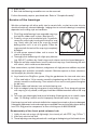
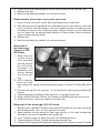
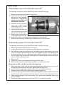
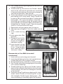
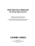
2. Place the adaptor onto the splines. When snug, the adaptor should leave an even gap
>««ÀÝ>ÌiÞÊÌ
iÊÜ`Ì
ÊvÊ>Ê«iViÊvÊ
paper between the hub and the
adaptor.
3. Insert the three bolts provided. In
an alternating pattern, hand tighten
adaptor bolts to pull adaptor down
evenly.
}ÕÀiÊÇÊÊÃÌ>ÊÀÌÀÊ>`>«ÌÀ
4
Rev. 12/12-A
{°Ê Ã
ÊÌÀµÕiÊÌÊÓnÊ°LÊÀÊΰ£È °ÊÊÊÌÊÛiÀÊÌ}
Ìi°
Adaptor removal
£°Ê ,iÛiÊÌ
iÊ`ÃVÊLÀ>iÊÀÌÀÊvÊÌÊVÛiÀÃÊÌ
iÊÌ
ÀiiÊÕÌ}ÊLÌð
Ó°Ê ,iÛiÊÌ
iÊÌ
ÀiiÊ>`>«ÌÀÊwÝ}ÊLÌð
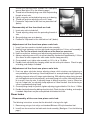
3. To remove the rotor adaptor from the tapered splines, pry between the adaptor and the hub
ÕÃ}ÊÌÜÊ««Ã}Ê«>ÃÌVÊÌÀiÊiÛiÀðÌÊÃ
Õ`Ê««ÊvvÊi>ÃÞ®°ÊÊÊÌÊÕÃiÊiÌ>ÊLiVÌÃ]Ê
such as screw drivers, to release the adaptor.
Wheel building - BMX
Cautions
ÀÃÊ}Ê8Ê
ÕLÃÊ>ÀiÊÃÕ««i`ÊÜÌ
ÊÎÉn»£ÈÊÝÊ£»ÊÃViÌÊV>«Ê>ÝiÊLÌðÊ,i«>ViiÌÃÊV>Ê
LiÊ«ÕÀV
>Ãi`Ê>ÌÊÃÌÊ
}
ʵÕ>ÌÞÊ
>À`Ü>ÀiÊÃÌÀiðÊ1ÃiÊ>ÊLÌÊvÊ}À>`iÊnÊÀÊiµÕÛ>iÌ°Ê1`iÀÊ
ÊVÀVÕÃÌ>Vi]ÊÃ
Õ`Ê>ʵÕVÊÀii>ÃiÊÃiÜiÀÊLiÊÃÕLÃÌÌÕÌi`ÊvÀÊÌ
iÊ>ÝiÊLÌð
ÊÌÊÕÃiÊV}ÃÊÌ
iÀÊÌ
>Ê8ÊV}ðÊ/
iÊ`ÀÛiÃ
iÊvÊÌ
iÊÀi>ÀÊ
ÕLÊ
>ÃÊ>ÊÕµÕiÊÃÞiÌÀV>Ê
ëi]Ê>`ÊV«>ÌLiÊÜÌ
ÊÃiÊ-
>]Ê>`ÊÌ
iÀÊ>vÌiÀÊ>ÀiÌÊV}ðÊ1ÃiÊvÊÌ
iÀÊV}ÃÊ
may cause chain slippage, or derailment, which could lead to bodily injury.
Installation and removal of the Cog
ÀÃÊ}Ê8Ê
ÕLÃÊÕÃiÊ>ÊV>ÃÃiÌÌiÊÃÌÞiÊV}ÊÕÌ}ÊÃÞÃÌi°Ê-«iV>ÊëiÃÊ>`ÊVÊ
À}ÃÊ
>ÛiÊLiiÊ`iÃ}i`ÊÌÊ>VVi«ÌÊ«ÀiÕʵÕ>ÌÞÊÃÌiiÊV}ðÊ
}ÃÊ>ÀiÊ>Û>>LiÊÊÃâiÃÊ
vÀÊ£ÓÌÊÌÊÓäÌ°Ê1Ã}ÊÃÌ>`>À`ÊV>ÃÃiÌÌiÊÌÃÊÞÕÊV>Êi>ÃÞÊÀiÛiÊ>`ÊV
>}iÊÞÕÀÊV}ð
Cog installation
£°Ê -iiVÌÊ`iÃÀi`ÊÌÌ
VÕÌÊ
}°
2. Slide cog onto driveshell spline. Cogs are symmetrical, and can be installed with either
side out.
3. Thread lock ring onto driveshell over cog.
{°Ê ÃiÀÌÊ-
>Ê™ÃÌÞiÊÌÊÌÊVÊÀ}]Ê>`ÊÌ}
ÌiÊÌÊÓäÊvÌ°LÊÀÊÓÇ°£Ó °
Cog removal
£°Ê
Ó°Ê
3.
4.
1Ã}Ê>ÊV
>ÊÜ
«]Ê
`ÊV}ÊÃÌ>Ì>ÀÞÊvÀÊVÕÌiÀVVÜÃiÊÀÌ>Ì°
ÃiÀÌÊ-
>Ê™ÃÌÞiÊV>ÃÃiÌÌiÊÌÊÌÊVÊÀ}°
Loosen and remove lock ring by rotating it until it is free from driveshell.
Slide cog off of spline.
HUB
SERVICE
MAINTENANCE
SCHEDULE
ÀÃÊ}ÊÕLÃÊ>ÀiÊ`iÃ}i`ÊÌÊ«ÀÛ`iÊ}ÊviÊ>`Ê
}
Ê«iÀvÀ>Vi°ÊiÞ`Ê>ÊVV>Ã>Ê
Rev. 12/12-A
5
>`ÕÃÌiÌ]Ê Ì
iÊ ÞÊ >Ìi>ViÊ iViÃÃ>ÀÞÊ ÃÊ Vi>}]Ê ÕLÀV>Ì}Ê Ì
iÊ ,}ÀÛi™ (see
“Maintenance of the RingDrive™ & driveshell»]Ê«>}iÊÈ®]Ê>`ÊÀiÕLÀV>Ì}ÊÌ
iÊLi>À}ÃÊÃiiÊ
ºi>À}ÊÃiÀÛVi»]Ê«>}iÊ®°Ê,`}ÊV`ÌÃÊÜÊ`iÌiÀiÊ
ÜÊvÌiÊÌÊ>Ì>ÊÞÕÀÊ
ÕLðÊÊ
ÃÊ>ÊLi}}Ê}Õ`ii]ÊÞÕÀÊ
ÕLÃÊÃ
Õ`ÊLiÊ>Ì>i`ÊiÛiÀÞÊÈ£ÓÊÌ
ÃÊÊÀ>Ê>`Ê
dry conditions and every 3 months in wet or muddy conditions.
/
iÊLi>À}ÃÊÊÞÕÀÊiÜÊ
ÀÃÊ}Ê
ÕLÃÊ>ÀiÊvÊÌ
iÊ
}
iÃÌʵÕ>ÌÞÊ>Û>>Li°ÊÜiÛiÀ]Ê>Ê
bearings will settle and eventually wear with use. Since looseness or “play” in the bearing
assembly can develop as a result of wear, Chris King hubs have been designed with an
adjustable bearing preload mechanism and any normal play can be eliminated (see the
>««À«À>Ìiʺ°°°`ÕÃÌiÌ»ÊÃiVÌ®°
RingDrive™ maintenance
À>Ê«ÀiÛiÌ>ÌÛiÊ>Ìi>ViÊvÊÌ
iÊ,}ÀÛi™ is simple and can be performed using
L>ÃVÊÌðÊÊ-iiʺ>Ìi>ViÊvÊ,}ÀÛi™ & driveshell”, page 6.) In many cases, a minor
cleaning and reapplication of lubricant is all that may be necessary. Judging when to perform
Ì
ÃÊL>ÃVÊ>Ìi>ViÊÃÊ`iÌiÀi`ÊLÞÊÀ`}ÊÃÌÞiÊ>`ÊV`ÌðÊÊÃÊ>ÊLi}}Ê}Õ`ii]Ê
ÞÕÀÊ
ÕLÃÊÃ
Õ`ÊLiÊ>Ì>i`ÊiÛiÀÞÊÈ£ÓÊÌ
ÃÊÊÀ>Ê>`Ê`ÀÞÊV`ÌÃÊ>`ÊiÛiÀÞÊÎÊ
months in wet or muddy conditions.
Lubrication
Normal conditions
ÊÀ>ÊÀ`}ÊV`ÌÃÊäc{Îc
®]ÊÕÀÊ,}ÀÛi™ lube is recommended for the bearings
>`ÊÌ
iÊ,}ÀÛi™. Do not substitute other brands of lube, as they may be too sticky for
the helix of the RingDrive™ inhibiting proper engagement.
Cold conditions
/ÊiÃÕÀiÊ«À«iÀÊi}>}iiÌÊÊÃÕLvÀiiâ}ÊV`ÌÃ]ÊwÀÃÌÊLiÊÃÕÀiÊÌ
>ÌÊÌ
iÀiÊÃÊÊÜ>ÌiÀÊÀÊ
moisture inside the hubshell. The hub may require an overhaul to ensure that the hub interior
ÃÊV«iÌiÞÊÜ>ÌiÀvÀii°Ê/
iÊÝÊÌ
iÊ}Ài>ÃiÊÊÌ
iÊ,}ÀÛi™ area, especially on the helical
ëiÃÊvÊÌ
iÊ`ÀÛiÃ
i]ÊÜÌ
Êx£äÊ`À«ÃÊvÊ*/ÊÊi°}°Ê/ÀÜÊ™®Ê°ÊvÊÞÕÊiÝ«iVÌÊÌÊLiÊÀ`}Ê
ÊÌi«iÀ>ÌÕÀiÃÊÌ
>ÌÊ>ÀiÊVÃÃÌiÌÞÊ>ÌÊÀÊLiÜÊvÀiiâ}ÊÀi«>ViÊ>ÊÌiÀ>ÊÕLiÊÜÌ
Ê>ʵÕ>ÌÞÊ
£äÜÊÃÞÌ
iÌVÊ°ÊÊÌÊÛiÀÊw°Ê7iÊÀiVVi`ÊÕÃ}Ê>ÊÃV>ÊÊ*i`ÀÃÁÊ-ÞÕLiÊÀÊ
LÊ£Á®Ê
Wet conditions
,`}Ê Ê ÜiÌÊ V`ÌÃÊ iViÃÃÌ>ÌiÃÊ ÀiÊ vÀiµÕiÌÊ ÃiÀÛVi°Ê "vÌiÊ Ì
ÃÊ ÃÊ >ÃÊ Ã«iÊ >ÃÊ
ÀiÛ}ÊÌ
iÊ>ÝiÊ>`Ê`ÀÛiÃ
iÊvÀÊÌ
iÊ
ÕL]ÊÀiÛ}Ê>ÞÊÃÌÕÀiÊvÀÊÃ`iÊÌ
iÊ
ÕLÊÃ
i]Ê
and applying more grease to the needle bearing. This should not replace periodic complete
`Ã>ÃÃiLÞÊ>`Ê>Ìi>Vi]ÊiëiV>ÞÊÊiÝÌÀiiÊÀÊ«À}i`ÊÜiÌÊV`Ìð
Note: Since it is nearly impossible to seal a hub from water and still have it spin freely, we have
`iÃ}i`ÊÕÀÊ
ÕLÃÊÌÊLiÊ>LiÊÌÊ«iÀ>ÌiÊÀ>ÞÊÜÌ
ÊÃiÊÜ>ÌiÀÊÌÀÕðÊÊÌ
Õ}
ÊÌ
iÊ
6
Rev. 12/12-A
bearings are stainless steel and will resist water induced corrosion, the lubricant will eventually
`iÌiÀÀ>Ìi]Ê i>`}Ê ÌÊ «Ài>ÌÕÀiÊ Li>À}Ê Üi>ÀÊ >`Ê «ÃÃLiÊ v>ÕÀi°Ê }
«ÀiÃÃÕÀiÊ Ã«À>ÞÊ
washing, transporting or riding the bicycle in the rain, or submersion in water while riding can
>Êi>`ÊÌÊÕLÀV>ÌÊVÌ>>ÌÊLÞÊÜ>ÌiÀ°ÊÊiÊ>Ü>ÀiÊvÊÌ
iÃiÊÃÌÕ>ÌÃÊ>`ÊÃiÀÛViÊÀiÊ
frequently when they occur.
In a pinch...
vÊ
ÀÃÊ}Ê,}ÀÛi™ lube in not available, a quality 10w synthetic oil may be substituted.
Do not substitute other brands of grease, as they may be too sticky for the helix of
the RingDrive™.ÊÊ,Õ}ÊÌ
iÊ
ÕLÊÊÊÜÊV>ÕÃiÊÌ
iÊ,}ÀÛi™ to be more audible, yet
functionally no different.
vÊ ÞÕÊ
>ÛiÊ >ÞÊ >``Ì>Ê µÕiÃÌÃ]Ê «i>ÃiÊ V>Ê ÕÀÊ /iV
V>Ê -iÀÛViÃÊ i«>ÀÌiÌÊ >ÌÊ
800.523.6008.
BASIC SERVICE
Front hubs
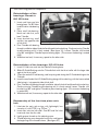
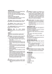
Disassembly of the
front two piece axle
hub (See figure 7)
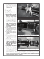
£°Ê ÃiÀÌÊ xÊ Ê
iÝÊ ÜÀiV
iÃÊ
ÌÊ LÌ
Ê i`ÃÊ vÊ >ÝiÊ
}ÕÀiÊÇÊÊÌÞ«V>ÊvÀÌʵÕVÊÀii>ÃiÊ
ÕL
assembly.*Pro Tip: Use a
bench vice to hold one of
the 5mm hex wrenches.
Ó°Ê `ÊivÌÊ
>`ÊÃÌ>Ì>ÀÞÊ>`ÊÌÕÀÊÀ}
ÌÊ
>`ÊVÕÌiÀVVÜÃiÊ£É{ÊÌÕÀÊÕÌÊ>ÃÃiLÞÊÃÊ
loose.
Î°Ê ÃiÊ>`ÊÕÃVÀiÜÊ>`ÕÃÌ}ÊViÊ>`Ê>ÝiÊi`ÊÕÌÊÌ
iÞÊ>ÀiÊvÀiiÊvÀÊ>Ê>Ýi°
{°Ê -`iÊÕÌÊ>Ê>Ýi°
x°Ê Ì
Ê
ÕLÊÃ
iÊLi>À}Ê>ÃÃiLiÃÊV>ÊÜÊLiÊ>VViÃÃi`°
ÕÀÌ
iÀÊ`Ã>ÃÃiLÞÊÀiµÕÀiÃÊëiV>âi`ÊÌðÊ,iviÀÊÌʺ
«iÌiÊÃÃiLÞ»°
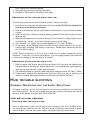
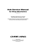
Disassembly of the front
one piece axle hub (See
figure 8)
£°Ê ÃiÀÌÊ >Ê Ó°xÊ
iÝÊ ÜÀiV
Ê ÌÊ
the adjusting clamp pinch bolt, and
loosen.
2. With adjusting cone facing towards
}ÕÀiÊnÊÌÞ«V>ÊvÀÌÊLÌÊ
ÕL
ÞÕ]Ê
`Ê ««ÃÌiÊ i`Ê vÊ >ÝiÊ
stationary, and rotate cone in a
VÕÌiÀÊVVÜÃiÊ`ÀiVÌ°ÊvÌiÀÊ
iÊV«iÌiÊÀiÛÕÌÊÌ
iÊ>`ÕÃÌ}ÊViÊÃ
Õ`ÊLiÊvÀiiÊvÀÊÌ
iÊ>Ýi°
Rev. 12/12-A
7
Î°Ê -`iÊÕÌÊ>Ýi°
{°Ê Ì
Ê
ÕLÊÃ
iÊLi>À}Ê>ÃÃiLiÃÊV>ÊÜÊLiÊ>VViÃÃi`
ÕÀÌ
iÀÊ`Ã>ÃÃiLÞÊÀiµÕÀiÃÊëiV>âi`ÊÌðÊ,iviÀÊÌʺ
«iÌiÊÃÃiLÞ»°
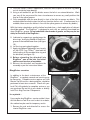
Service of the bearings
We offer our bearings with either quality steel or ceramic balls, so short term water intrusion
should not lead to any substantial damage. Judging when to service the bearings is completely
dependent on the riding style and conditions.
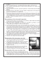
1. Chris King sealed bearings have removable snap rings
that hold the rubber seals in place. (See figure 9.)
2. Carefully, using a small screwdriver, pick, or penknife,
remove the snap ring by inserting tool into split of snap
ring. Gently work one end of the snap ring toward
bearing center until it is out of its groove. Follow the
ring around with the tool until the snap ring is completely
dislodged.
Î°Ê vÌÊ >`Ê ÀiÛiÊ iÝ«Ãi`Ê ÀÕLLiÀÊ Ãi>Ê ÌÊ >VViÃÃÊ Ì
iÊ
}ÕÀiÊÊÊÃi>ÊEÊÃ>«ÊÀ}
interior of the bearing.
4. Thoroughly flush the bearing with a light spray lubricant
i°}°Ê7{ä™®Ê>`ÊLÜÊ`ÀÞ°ÊÛ`ÊÕÃ}ÊVÕ>ÃÌVÊVi>iÀÃÊ>`ÊVÌÀÕÃÊL>Ãi`Ê`iÌiÀ}iÌðÊÊ
x°Ê 7«iÊ`ÀÌÊ>`ÊÌ
iÀÊVÌ>>ÌÃÊvÀÊÌ
iÊÃi>ÃÊ>`ÊÃ>«ÊÀ}ðÊÛ`ÊVi>}ÊÌ
iÊÃi>ÃÊ
with solvent, which could cause deterioration.
Ìi\ÊÃiÊÃÛiÌÃ]ÊÃÞÌ
iÌVÊÕLÀV>ÌÃ]Ê>`Ê}Ài>ÃiÃÊÜÌ
Ê
}
«ÀiÃÃÕÀiÊ>``ÌÛiÃÊ>ÞÊ>ÌÌ>VÊ
>`Ê`>>}iÊÃi>ÃÊ>`ÊÌ
iÀÊiÌ>VÊ>ÌiÀ>ðÊâiÊiÝ«ÃÕÀiÊÌÊÌ
iÃiÊÃÕLÃÌ>ViÃÊ
and thoroughly dry hub after cleaning.
È°Ê >ÞÊ>ÊLi>`ÊvÊÕÀÊ,}ÀÛi™ grease, filling the gap between the inner and outer races
1/3 for steel balls or 1/4 for ceramic around the large bearing and 3/4 for steel or 1/3 for
ceramic around the small bearing. Then rotate the inner race to work grease throughout
the ball area.
Ç°Ê ,i«>ViÊÀÕLLiÀÊÃi>ÊLiÌÜiiÊiÀÊ>`ÊÕÌiÀÊLi>À}ÊÀ>Vi°
8. Insert one edge of snap ring into groove of outer bearing race. Press along entire groove
until snap ring is fully seated; a small gap should be visible between both ends of the snap
ring.
9. Turn inner race of bearing by hand to test for binding. If bearings do not run smooth, repeat
ÃÌi«ÃÊ£°Ê`}ÊÃÊvÌiÊ>ÊÀiÃÕÌÊvÊ«À«iÀÞÊÃi>Ìi`ÊÃi>ÃÊ>`ÉÀÊÃ>«ÊÀ}ð
1Ãi`ÊÃ>«ÊÀ}ÃÊ>`ÊÃi>ÃÊV>ÊLiÊÀiÃÌ>i`ÊÕiÃÃÊÜ>À«i`]Ê«ÕVÌÕÀi`]ÊÀÊÌ
iÀÜÃiÊ`>>}i`°Ê
If damaged, replacement seals and snap rings are available from your local bike shop or directly
vÀÊ
ÀÃÊ}Ê«ÀiVÃÊV«iÌÃÊ>ÌÊÜÜÜ°V
ÀÃ}°VÊÀÊnääxÎÎÈään°
Reassembly of the front quick-release hub
£°Ê }
ÌÞÊÊ>Ê>ÝiÊÀ}ÃÊÜÌ
Ê}
ÌÜi}
Ì]ÊÜÊÛÃVÃÌÞÊ]ÊÜÌ
Ê*/ÊÊi°}°Ê/ÀÜÊ™).
Ó°Ê ÃiÀÌÊ>Ê>ÝiÊÌÊ
ÕLÊÃ
i°
Î°Ê /
Ài>`Ê>`ÕÃÌ}ÊViÊ>}Ê>ÝiÊi`ÊÕÌÊ>ÊÃ>Ê}>«Ê>ÌÊÌ
iÊLi}}ÊvÊÌ
iÊÌ
Ài>`ÃÊÃ
ÜðÊ
8
Rev. 12/12-A
{°Ê
x°Ê
È°Ê
Ç°Ê
Grease the adjusting cone threads with waterproof
grease (See figure 10 on the following page.)
/
Ài>`Ê>ÝiÊi`Ê>`Ê>`ÕÃÌ}ÊViÊÌÊÌ
iÊ«ÀÌÀÕ`}Ê
Ì
Ài>`ÃÊvÊ>Ê>Ýi°
}
ÌÞÊÃÕ}Ê>ÝiÊi`Ê>`Ê>`ÕÃÌ}ÊViÊÕ«ÊÌÊLi>À}°
/
Ài>`Ê>ÝiÊi`ÊÌÊ>`ÕÃÌ}ÊViÊÕÌÊÌÊÃ̫ð
*ÀVii`ÊÌʺ`ÕÃÌiÌÊvÊÌ
iÊvÀÌÊÌÜÊ«iViÊ>ÝiÊ
ÕL»Ê
(below).
Reassembly of the front bolt-on hub
£°Ê ÃiÀÌÊ>Ê>ÝiÊÌÊ
ÕLÊÃ
i°
2. Thread adjusting clamp onto the protruding threads of
}ÕÀiÊ£äÊÊ>`ÕÃÌ}ÊVi
>Ýi°
3. Snug adjusting cone up to bearing.
{°Ê *ÀVii`ÊÌʺ`ÕÃÌiÌÊvÊÌ
iÊvÀÌÊLÌÊ
ÕL»ÊLiÜ®°
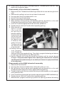
Adjustment of the front two piece axle hub
£°Ê ÃiÀÌÊxÊÊ
iÝÊÜÀiV
iÃÊÌÊLÌ
Êi`ÃÊvÊ>ÝiÊ>ÃÃiLÞ°
Ó°Ê `ÊivÌÊ
>`ÊÃÌ>Ì>ÀÞÊ>`ÊÌÕÀÊÀ}
ÌÊ
>`ÊVÕÌiÀVVÜÃiÊ£É{ÊÌÕÀÊÕÌÊ>ÃÃiLÞÊÃÊ
loose.*Pro Tip: Use a bench vice to hold one of the 5mm hex wrenches.
Î°Ê `Ê
iÝÊÜÀiV
iÃÊÃÌ>Ì>ÀÞÊ>`Ê>`ÕÃÌÊLi>À}Ê«Ài>`ÊÜÌ
Ê>`ÕÃÌ}ÊVi°
{°Ê `Û>ViÊ>`ÕÃÌ}ÊViÊÕÌÊÌÊÕÃÌÊVÌ>VÌÃÊLi>À}]ÊÌ
iÊL>VÊvvÊ>««ÀÝ>ÌiÞʣɣÈÊÌÕÀÊ
Ì
ÃÊ>ÜÃÊvÀÊ>ÝiÊV«ÀiÃÃÊÜ
iÊÕ`iÀÊÃiÜiÀÊV>«Ê«ÀiÃÃÕÀi®°
x°Ê "ViÊ«Ài>`ÊÃÊÃiÌ]ÊÌ}
ÌiÊ>ÝiÊ>ÃÃiLÞÊÌÊ££äÊ°L°ÊÀÊ£Ó°{Î
È°Ê ÕLiÊV
iVÊ>`ÕÃÌiÌÊLÞÊV>«}ÊÜ
iiÊÌÊvÀÊÜÌ
ʵÕVÀii>Ãi°ÊÊ
iVÊvÀÊ«>ÞÊ
or binding, and readjust if needed.
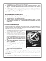
Adjustment of the front one piece axle hub
£°Ê ÀÌÊ iÊ «iViÊ >ÝiÊ
ÕLÃÊ vi>ÌÕÀiÊ >`ÕÃÌ}Ê V>«ÃÊ Ü
V
Ê âiÊ ÛiÀÊ Ì}
Ìi}Ê ÀÊ
over preloading of the bearings. Normal adjustment is accomplished by finger tightening
>`ÕÃÌ}ÊÀ}ÊÌÊ>ÝiÊÕÌÊÌÊÃÌ«ÃÊ>}>ÃÌÊLi>À}°Ê7Ì
Ê>`ÕÃÌ}ÊV>«Êv>V}ÊÌÜ>À`ÃÊ
ÞÕ]Ê
`Ê««ÃÌiÊi`ÊvÊ>ÝiÊÃÌ>Ì>ÀÞ]Ê>`ÊÀÌ>ÌiÊV>«ÊÊ>ÊVÕÌiÀÊVVÜÃiÊ`ÀiVÌÊ
ÌÊÕÃVÀiÜÊÌÊvÀÊÌ
iÊ>Ýi°ÊvÊ>`ÕÃÌ}ÊV>«ÊÃÊ`vwVÕÌÊÌÊ«ÃÌ]ÊÃiÀÌÊ>ÊÓ°xÊ
iÝÊ
iÞÊÌʺ
i«iÀÊ
i»ÊÊ>`ÕÃÌ}ÊV>«Ê>`>ViÌÊÌÊÓ°xÊ
iÝÊLÌ°Ê1ÃiÊÌ
iÊ
iÝÊiÞÊ>ÃÊ
a lever to preload adjusting clamp
Ó°Ê "ViÊ>`ÕÃÌ}ÊV>«ÊÃÊÊ«ÃÌ]ÊÌ}
ÌiÊ>`ÕÃÌ}ÊÀ}Ê«V
ÊLÌÊÌÊ£ä°L°ÊÀÊ£°£Î °
Î°Ê ÕLiÊV
iVÊ>`ÕÃÌiÌÊLÞÊLÌ}ÊÜ
iiÊÌÊvÀ°Ê
iVÊvÀÊ«>ÞÊÀÊL`}]Ê>`ÊÀi>`ÕÃÌÊ
vÊii`i`°Ê`ÕÃÌiÌÊ>ÞÊLiÊ>VV«Ã
i`ÊÜ
iÊLÌi`ÊÌÊvÀ°
Rear hubs
Disassembly of the rear two piece axle hub
The following instructions assume that the driveshell is facing to the right:
£°Ê ,iÛiÊV}ÊÕÃ}Ê>ÊV
>ÊÜ
«]Ê>`ÊÃÌ>`>À`Ê-
>ÊÃÌÞiÊvÀiiÜ
iiÊÌ°
Ó°Ê ÃiÀÌÊxÊÊ
iÝÊÜÀiV
iÃÊÌÊLÌ
Êi`ÃÊvÊ>ÝiÊ>ÃÃiLÞ°Ê-iiÊw}ÕÀiÊ££ÊÊÌ
iÊvÜ}Ê
page.)
Rev. 12/12-A
9
Î°Ê `Ê ivÌÊ
>`Ê ÃÌ>Ì>ÀÞÊ
and turn right hand
counterclockwise 1/4 turn
until assembly is loose.
4. L o o s e n a n d u n s c r e w
>`ÕÃÌ}Ê ViÊ >`Ê >ÝiÊ
end until they are free from
Ì
iÊ>Ê>Ýi°
x°Ê ,iÛiÊ>Ê>ÝiÊLÞÊ«Õ}Ê
on drive side end of main
>Ýi°
È°Ê `Ê
ÕLÊ ÀÊ Ü
iiÊ Ê iÊ
}ÕÀiÊ££ÊÊ`Ã>ÃÃiLiÊ>Ê>Ýi
hand and pull driveshell out
with the other.
Ç°Ê Ì
Ê
ÕLÊÃ
iÊ>`Ê`ÀÛiÃ
iÊLi>À}Ê>ÃÃiLiÃÊV>ÊÜÊLiÊ>VViÃÃi`°ÊÊ
ÕÀÌ
iÀÊ`Ã>ÃÃiLÞÊÀiµÕÀiÃÊëiV>âi`ÊÌðÊ,iviÀÊÌʺ
«iÌiÊÃÃiLÞ»°
Disassembly of the rear one piece axle hub
The following instructions assume that the driveshell is facing to the right:
£°Ê ,iÛiÊV}ÊÕÃ}Ê>ÊV
>ÊÜ
«]Ê>`ÊÃÌ>`>À`Ê-
>ÊÃÌÞiÊvÀiiÜ
iiÊÌ°
Ó°Ê ÃiÀÌÊ>ÊÓ°xÊ
iÝÊÜÀiV
ÊÌÊ>`ÕÃÌ}ÊV>«Ê«V
ÊLÌ]Ê>`ÊÃi°
Î°Ê 7Ì
Ê>`ÕÃÌ}ÊV>«Êv>V}ÊÌÜ>À`ÃÊÞÕ]Ê
`Ê««ÃÌiÊi`ÊvÊ>ÝiÊÃÌ>Ì>ÀÞ]Ê>`ÊÀÌ>ÌiÊ
ViÊÊ>ÊVÕÌiÀÊVVÜÃiÊ`ÀiVÌ°ÊvÌiÀÊiÊV«iÌiÊÀiÛÕÌÊÌ
iÊ>`ÕÃÌ}ÊViÊ
Ã
Õ`ÊLiÊvÀiiÊvÀÊÌ
iÊ>Ýi°ÊvÊ>`ÕÃÌ}ÊV>«ÊÃÊ`vwVÕÌÊÌÊ«ÃÌ]ÊÃiÀÌÊ>ÊÓ°xÊ
iÝÊ
iÞÊÌʺ
i«iÀÊ
i»ÊÊ>`ÕÃÌ}ÊV>«Ê>`>ViÌÊÌÊÓ°xÊ
iÝÊLÌ°Ê1ÃiÊÌ
iÊ
iÝÊiÞÊ>ÃÊ
a lever to unscrew adjusting clamp
{°Ê -`iÊÕÌÊ>Ýi°
5 hold hub or wheel in one hand and pull driveshell with other.
È°Ê Ì
Ê
ÕLÊÃ
iÊ>`Ê`ÀÛiÃ
iÊLi>À}Ê>ÃÃiLiÃÊV>ÊÜÊLiÊ>VViÃÃi`°ÊÊÊÊ
ÕÀÌ
iÀÊ`Ã>ÃÃiLÞÊÀiµÕÀiÃÊëiV>âi`ÊÌðÊ,iviÀÊ
Ìʺ
«iÌiÊÃÃiLÞ»°
Service of the bearings
We offer our bearings with either quality steel or
ceramic balls, so short term water intrusion should
not lead to any substantial damage. Judging when
to service the bearings is completely dependent on
the riding style and conditions.
1. Chris King sealed bearings have removable snap
rings that hold the rubber seals in place.
2. Carefully, using a small screwdriver, pick, or
penknife, remove the snap ring by inserting tool
into split of snap ring. Gently work one end of
10
}ÕÀiÊ£ÓÊÊÀiÛiÊÃ>«ÊÀ}
Rev. 12/12-A
the snap ring toward bearing center until it is out of its groove. Follow the ring around with
the tool until the snap ring is completely dislodged. (see figure 12.)
Î°Ê vÌÊ>`ÊÀiÛiÊiÝ«Ãi`ÊÀÕLLiÀÊÃi>ÊÌÊ>VViÃÃÊÌ
iÊÌiÀÀÊvÊÌ
iÊLi>À}°
{°Ê /
ÀÕ}
ÞÊyÕÃ
ÊÌ
iÊLi>À}ÊÜÌ
Ê>Ê}
ÌÊëÀ>ÞÊÕLÀV>ÌÊi°}°Ê7{ä™) and blow dry with
an air compressor.
x°Ê 7«iÊ`ÀÌÊ>`ÊÌ
iÀÊVÌ>>ÌÃÊvÀÊÌ
iÊÃi>ÃÊ>`ÊÃ>«ÊÀ}ðÊÛ`ÊVi>}ÊÌ
iÊÃi>ÃÊ
with solvent, which could cause deterioration.
"/\Ê-iÊÃÛiÌÃ]ÊÃÞÌ
iÌVÊÕLÀV>ÌÃ]Ê>`Ê}Ài>ÃiÃÊÜÌ
Ê
}
«ÀiÃÃÕÀiÊ>``ÌÛiÃÊ>ÞÊ>ÌÌ>VÊ
>`Ê`>>}iÊÃi>ÃÊ>`ÊÌ
iÀÊiÌ>VÊ>ÌiÀ>ðÊâiÊiÝ«ÃÕÀiÊÌÊÌ
iÃiÊÃÕLÃÌ>ViÃÊ
>`ÊÌ
ÀÕ}
ÞÊ`ÀÞÊ
ÕLÊ>vÌiÀÊVi>}°ÊÛ`ÊÌ
iÊÕÃiÊvÊVÕ>ÃÌVÊ>`Ê>V`VÊ`i}Ài>ÃiÀÃÊiÊ
citrus cleaners.
È°Ê >ÞÊ>ÊLi>`ÊvÊÕÀÊ,}ÀÛi™ grease, filling the gap between the inner and outer races
1/3 for steel balls or 1/4 for ceramic around the large bearing and 3/4 for steel or 1/3 for
ceramic around the small bearing. Then rotate the inner race to work grease throughout
the ball area.
Ç°Ê ,i«>ViÊÀÕLLiÀÊÃi>ÊLiÌÜiiÊiÀÊ>`ÊÕÌiÀÊLi>À}ÊÀ>Vi°Ê* When installing old seal be
sure to install seal in its original orientation.
8. Insert one edge of snap ring into groove of outer bearing race. Press along entire groove
until snap ring is fully seated; a small gap should be visible between both ends of the snap
ring.
9. Turn inner race of bearing by hand to test for binding. If bearings do not run smooth, repeat
ÃÌi«ÃÊ£°Ê`}ÊÃÊvÌiÊ>ÊÀiÃÕÌÊvÊ«À«iÀÞÊÃi>Ìi`ÊÃi>ÃÊ>`ÉÀÊÃ>«ÊÀ}ð
*Used snap rings and seals can be reinstalled unless warped, punctured, or otherwise
damaged. If damaged, replacement seals and snap rings are available from your local
bike shop or directly from Chris King precision components.
Maintenance of RingDrive™ & driveshell
Inspection
>Û}ÊÀiÛi`ÊÌ
iÊ>ÝiÊ>`Ê`ÀÛiÃ
iÊ>ÃÊÃÌÀÕVÌi`Ê>LÛi®]ÊÌ
iÊ,}ÀÛi™ is accessible
Ì
ÀÕ}
Ê Ì
iÊ >À}iÊ Ã`iÊ vÊ Ì
iÊ
ÕLÊ Ã
i°Ê 6ÃÕ>ÞÊ Ã«iVÌÊ Ì
iÊ
ÕL½ÃÊ ÌiÀÀ°Ê Ê 1`iÀÊ À>Ê
V`ÌÃÊÌ
iÊ}Ài>ÃiÊÃ
Õ`ÊÊÃÌÊ>`Ê>ÞÊ
>ÛiÊ`>Àii`ÊÃ}
ÌÞ°ÊÊÊ`iÃÌÊwÊÃ
Õ`Ê
coat the moving parts.
ÃÊÜÌ
ÊÌ
iÊÀiÃÌÊvÊÌ
iÊ
ÕL]ÊÌ
iÊ,}ÀÛi™ is designed to operate with some water contamination.
Water intrusion can usually be remedied with basic maintenance.
ÜiÛiÀ]ÊvÊvÀi}Ê`iLÀÃÊÃÊ`iÌiVÌ>LiÊÊÌ
iÊ}Ài>ÃiÊ>`ÉÀÊÌ
iÊ}Ài>ÃiÊÃÊ
>À`ÊÀÊ`ÀÞ]ÊÌ
iÊ
>ÊV«iÌiÊÀiÛ>Ê>`ÊÃiÀÛV}ÊvÊÌ
iÊ,}ÀÛi™ is necessary.
Basic maintenance
£°Ê />iÊ>ÊVi>]ÊÌÊvÀiiÊÀ>}Ê>`ÊÜ«iÊ>ÞÊëiÌÊÕLÀV>ÌÊvÀÊÃ`iÊÌ
iÊ
ÕLÊÃ
i°ÊÊiÊV>ÀivÕÊ
not to drag any dirt or debris from outside the hub into the interior area.
Rev. 12/12-A
11
2. Once the interior is clean in appearance, locate the helical splines of the drive ring about
an inch inside the large bearing.
Î°Ê 1Ã}Ê>ÊÃvÌÊÌÌ
LÀÕÃ
]Ê«ÕÊÌ
iÊLÀÃÌiÃÊ>VÀÃÃÊÌ
iÊ
iÝÊÊ>ÊÕÌÜ>À`Ê`ÀiVÌ°ÊÊ7ÀÊ
your way all the way around the inner circumference to remove any small particles that
may be in the spline grooves.
{°Ê "ViÊV«iÌi`]ÊÜ«iÊÌ
iÊ>Ài>Ê`ÀiVÌÞÊÊvÀÌÊvÊÌ
iÊ
iÝÊÌÊÀiÛiÊ>ÞÊ`iLÀðÊÊ/
ÃÊ
iÌ
`ÊÃ
Õ`ÊLiÊÕÃi`ÊÌÊVi>ÊÌ
iÊ
iÝÊÊÌ
iÊ`ÀÛiÊÃ
iÊ>ÃÊÜi°ÊÊvÊV«ÀiÃÃi`Ê>ÀÊÃÊ
>Û>>Li]ÊLÜÊ>VÀÃÃÊÌ
iÊ
iÝiÃÊÊiÊÜÌ
ÊÌ
iÊëiÊ}ÀÛiÃÊÌÊÀiÛiÊ>ÞÊ`iLÀð®
7Ì
ÊÌ
iÊÌiÀÀÊÜ«i`Ê`ÜÊ>`ÊÌ
iÊ
iÝiÃÊLÀÕÃ
i`ÊVi>]Ê>ÊvÀiÃ
Ê>««V>ÌÊvÊÕLÀV>ÌÊ
Ã
Õ`ÊLiÊ>««i`°ÊÊ/
iÊ,}ÀÛi™ is designed to work with our specially formulated low
Ã
i>ÀÊ,}ÀÛi™ grease. Do not substitute other brands of grease, as they may be too
sticky for the helix of the RingDrive™.
5. Lubricate by reopening a gap between the
`ÀÛiÊÀ}Ã]Ê>`Ê>Þ}Ê>ÊLi>`ÊvÊ,}ÀÛi™
grease on the teeth between them (see figure
13).
6. Let the rings spring back together .
Ç°Ê ««ÞÊ>ÊviÜÊ`À«ÃÊvÊ}
ÌÜi}
Ì]ÊÜÊÛÃVÃÌÞÊ
]ÊÜÌ
Ê*/ÊÊi°}°Ê/ÀÜÊ™) onto both the
helical splines of the movable drive ring and
the driveshell (see figure 14).
8. Before reinserting the driveshell into
RingDrive™ area of the hub, the helical
splines must be clean of any debris.
°Ê ,iÃiÀÌÊ Ì
iÊ `ÀÛiÃ
iÊ >`Ê V«iÌiÊ Ì
iÊ
assembly as per the instructions below.
RingDrive™ service
}ÕÀiÊ£ÎÊÊÕLiÊ,}ÀÛi™ teeth
In addition to the basic maintenance of the
,}ÀÛi™, a complete removal and servicing may
LiÊiViÃÃ>ÀÞ°ÊÊ
«iÌiÊÃiÀÛViÊÀiµÕÀiÃÊÕÀÊÕLÊ
Service Tool Kit and, as a basic guideline, should be
performed at least once a season. Check with your
local Chris King dealer for complete service or you
may purchase the tool kit at your dealer or directly
from Chris King Precision Components.
In a pinch...
vÊÞÕÊii`ÊÌÊ`Ê>Ê,}ÀÛi™ service and don’t have
Ì
iÊÕLÊ-iÀÛViÊ/ÊÌÊÀÊV>½ÌÊ>iÊÌÊÌÊ>Ê`i>iÀ]Ê
this method may be used for temporary results:
£°Ê ,iÛiÊ Ì
iÊ >ÝiÊ >`Ê `ÀÛiÃ
iÊ ÌÊ >VViÃÃÊ Ì
iÊ
ÌiÀÀÊ,}ÀÛi™ area.
12
}ÕÀiÊ£{ÊÊÕLiÊ
iV>ÊëiÃ
Rev. 12/12-A
Ó°Ê *ÕÃ
ÊÌ
iÊ`ÀÛiÊÀ}ÊÜÌ
Ê
iV>ÊëiÃÊÜ>À`ÊÌÊ«iÊ>Ê}>«]ÊiÝ«Ã}ÊÌ
iÊ`ÀÛiÊÌiiÌ
Ê>`Ê
yÕÃ
ÊÌ
iÊÌiÀÀÊÜÌ
Ê>Ê}
ÌÊÃÛiÌL>Ãi`ÊëÀ>ÞÊÕLÀV>ÌÊi°}°]7{ä™) until the area
>««i>ÀÃÊVi>°ÊÜÊvvÊ>ÞÊÀi>}ÊÃÛiÌÊÕÌÊV«iÌiÞÊ`ÀÞ°
Î°Ê vÊ VÌ>>ÌÊ ÃÊ ÃÌÊ >««>ÀiÌ]Ê Ài«i>ÌÊ yÕÃ
}Ê >`Ê LÜÊ V«iÌiÞÊ `ÀÞ°Ê Ê V«iÌiÊ
service of both hub shell bearings should be performed at the same time.
4. Finish by performing the basic maintenance as instructed above.
x°Ê vÌiÀÊ>ÃÃiLÞ]ÊV>ÀivÕÞÊ
>`ÊÌiÃÌÊ
ÕLÊvÀÊÃÌ
Ê«iÀ>ÌÊvÊÌ
iÊLi>À}ÃÊ>`ÊVÃÃÌiÌ]Ê
«ÃÌÛiÊi}>}iiÌÊvÊÌ
iÊ,}ÀÛi™. If performance is not improved to original quality,
>ÊV«iÌiÊ,}ÀÛi™ removal service must be performed.
Reinstallation of the driveshell assembly
1. Check the helical splines of the driveshell for any particles or debris before proceeding;
the driveshell must be clean before installing!
Ó°Ê ««ÞÊÃiÛiÀ>Ê`À«ÃÊvÊ}
ÌÜi}
Ì]ÊÜÊÛÃVÃÌÞÊ]ÊÜÌ
Ê*/ÊÊi°}°Ê/ÀÜÊ ™) on the
iV>Êëi]Ê"À}]Ê>`ÊÌ>«iÀi`Ê`>iÌiÀÊ`ÀiVÌÞÊ>`>ViÌÊÌ
iÊ"À}°
Î°Ê ÃiÀÌÊ`ÀÛiÊÃ
iÊÌÊ
ÕLÊÃ
i]ÊÃÜÞ°ÊÊÃÊÌ
iÊ`ÀÛiÃ
iÊiÌiÀÃÊÌ
iÊ,}ÀÛi™ area, it will
Ü>ÌÊÌÊiÃ
ÊÌ
iÊ
iV>ÊëiÃÊvÊÌ
iÊ`ÀÛiÊÀ}°ÊÊÃÊÌÊLi}ÃÊÌÊiÃ
]Ê>ÊÃ}
ÌÊVVÜÃiÊ
turning motion of the driveshell will help pull it into the hub shell. Continue twisting as the
`ÀÛiÊÃ
iÊ«ÕÃÊÌÃivÊÌÊÌ
iÊ
ÕLÊÃ
i°ÊÌÊÌ
iÊLÌÌÊvÊÌÃÊÜ>À`ÊÛiiÌ]Ê>Ê>Õ`LiÊ
“click” or “pop” sound indicates that it has found home and is fully seated. (The “click”
or “pop” is the spring retainer popping onto the driveshell and the driveshell hitting the
bearing, indicating the driveshell is fully inserted.)
{°ÊÊ ÃiÀÌÊ>Êw}iÀÊvÀÊÌ
iÊ`ÀÛiÊÃ`iÊÌÊÕÃÕÀiÊ«À«iÀÊÃi>Ì}°Ê
5. Test engagement by spinning driveshell in both directions. If it does not engage, remove
`ÀÛiÃ
i]ÊV
iVÊVi>iÃÃÊ>`ÊÀiÃiÀÌ°ÊÊ,iÌiÃÌ°
È°Ê /
iÊ
ÕLÊÃÊÜÊÀi>`ÞÊÌÊ
>ÛiÊÌ
iÊ>ÝiÊÃÌ>i`°
Reassembly of the rear two piece axle hub
The following instructions
assume that the driveshell is
facing to the right:
£°Ê ÕLiÊ À}Ê >`Ê >ÝiÊ
sleeve with lightweight,
low viscosity oil, with
*/ÊÊi°}°Ê/ÀÜÊ™)
Ó°Ê ÃiÀÌÊ >Ê >ÝiÊ Ì
ÀÕ}
Ê
drive shell and completely
ÌÊ
ÕL°Ê Ê ÝiÊ Ã
Õ`Ê
protrude slightly through
the non drive side bearing.
}ÕÀiÊ£xÊÊ>Ê>Ýi
}ÕÀiÊ£ÈÊÊ>`ÕÃÌ}ÊVi
(See figure 15.)
3. Grease the adjusting cone
threads with waterproof grease
{°Ê /
Ài>`Ê>`ÕÃÌ}ÊViÊ>}Ê>ÝiÊi`ÊÕÌÊ>ÊÃ>Ê}>«Ê>ÌÊÌ
iÊLi}}ÊvÊÌ
iÊÌ
Ài>`ÃÊ
Rev. 12/12-A
13
shows. (See figure 16.)
x°Ê /
Ài>`Ê>ÝiÊi`Ê>`Ê>`ÕÃÌ}ÊViÊÌÊÌ
iÊ«ÀÌÀÕ`}ÊÌ
Ài>`ÃÊvÊ>Ê>Ýi°
È°Ê }
ÌÞÊÃÕ}Ê>ÝiÊi`Ê>`Ê>`ÕÃÌ}ÊViÊÕ«ÊÌÊLi>À}°
Ç°Ê /
Ài>`Ê>ÝiÊi`ÊÌÊ>`ÕÃÌ}ÊViÊÕÌÊÌÊÃ̫ð
n°ÊÊ *ÀVii`ÊÌʺ`ÕÃÌiÌÊvÊÌ
iÊÀi>ÀʵÕVÀii>ÃiÊ
ÕL»ÊLiÜ°
"/\Ê /Ê «ÀÛiÊ «iÀvÀ>Vi]Ê Ì
iÊ >ÝiÃÊ
>ÛiÊ LiiÊ «ÀiVÃiÞÊ >ÌV
i`Ê ÜÌ
Ê Ì
iÊ ii`iÊ
Li>À}ÃÊÊÌ
iÊ`ÀÛiÃ
i°ÊiÊÃÕÀiÊÌÊVLiÊÞÊiÊÕLiÀi`Ê«>ÀÌÃ]Êi°}°]Ê{Ê>ÝiÊÜÌ
Ê
{Êii`iÊLi>À}ÊÀ>Vi®°
Reassembly of the rear one piece axle hub
The following instructions assume that the driveshell is facing to the right:
£°Ê}
ÌÞÊÊ>ÊÀ}ÃÊ>`ÊLi>À}ÊVÌ>VÌÊÃÕÀv>ViÃÊÜÌ
Ê}
ÌÜi}
Ì]ÊÜÊÛÃVÃÌÞÊ]ÊÜÌ
Ê
*/ÊÊi°}°Ê/ÀÜÊ™).
2. Insert driveshell into the hub shell; turn in a clockwise motion while letting it pull itself in .
Ê`ÃÌVÌÛiÊVVÊÃÕ`ÊÜÊ`V>ÌiÊÌ
>ÌÊÌ
iÊ`ÀÛiÃ
iÊÃÊwÀÞÊÃi>Ìi`°
Î°Ê ÃiÀÌÊ>Ê>Ýi]ÊÃ>Êi`ÊwÀÃÌÊÌÊ`ÀÛiÃ
i°Ê
ÌÕiÊÕÌÊ>ÝiÊÃÊÌ
ÀÕ}
ÊÌ
iÊ
ÕLÊ>`Ê
large end is firmly seated in driveshell.
{°Ê /
Ài>`Ê>`ÕÃÌ}ÊV>«ÊÌÊÌ
iÊ«ÀÌÀÕ`}ÊÌ
Ài>`ÃÊvÊ>Ýi°
5. Snug adjusting clamp up to bearing.
È°Ê *ÀVii`ÊÌʺ`ÕÃÌiÌÊvÊÌ
iÊÀi>ÀÊiÊ«iViÊ
ÕL»ÊLiÜ®°
Adjustment of the rear two piece axle hub
The following instructions assume that the drive shell is facing to the right:
£°Ê ÃiÀÌÊxÊÊ
iÝÊÜÀiV
iÃÊÌÊLÌ
Êi`ÃÊvÊÌ
iÊ>ÝiÊ>ÃÃiLÞ°*Pro Tip: Use a bench vice
to hold one of the 5mm hex wrenches.
Ó°Ê `ÊivÌÊÃ`iÊÃÌ>Ì>ÀÞÊ>`ÊÌÕÀÊÀ}
ÌÊ
>`ÊVÕÌiÀVVÜÃiÊ£É{ÊÌÕÀÊÕÌÊÌ
iÊ>ÃÃiLÞÊ
is loose.
Î°Ê `Ê
iÝÊÜÀiV
iÃÊÃÌ>Ì>ÀÞÊ>`Ê>`ÕÃÌÊLi>À}Ê«Ài>`ÊÜÌ
ÊÌ
iÊ>`ÕÃÌ}ÊÌ
iÊ
ÕLÊViÊ
adjusting tool.
{°Ê `Û>ViÊ>`ÕÃÌ}ÊViÊÕÌÊÌÊVÌ>VÌÃÊLi>À}°Ê/
iÊÀi>ÀÊ
ÕLÊÌ>iÃÊ>ÊÃ}
ÌÞÊ
}
iÀÊ>ÕÌÊ
of preload than “no play”, since some settling may occur while riding.
x°Ê "ViÊ«Ài>`ÊÃÊÃiÌ]ÊÌ}
ÌiÊ>ÝiÊ>ÃÃiLÞÊÌ}iÌ
iÀÊÌÊ££ä°L°ÊÀÊ£Ó°{Î °
È°Ê
iVÊ>`ÕÃÌiÌÊLÞÊV>«}ÊÜ
iiÊÌÊvÀ>iÊÜÌ
ʵÕVÀii>Ãi°Ê,`iÊvÀÊx£äÊÕÌiÃ]Ê
V
iVÊvÀÊ«>ÞÊÀÊL`}]Ê>`ÊÀi>`ÕÃÌÊ>ÃÊiViÃÃ>ÀÞ°ÊÊÕLiÊV
iVÊ>`ÕÃÌiÌÊ>vÌiÀÊÌ
iÊ
wÀÃÌÊx£äÊiÃÊvÊÀ`}°
"/\Ê ÀÀiVÌÊ >`ÕÃÌiÌÊ vÊ Ì
iÊ Ài>ÀÊ
ÕLÊ ÃÊ iViÃÃ>ÀÞÊ vÀÊ «À«iÀÊ i}>}iiÌÊ vÊ Ì
iÊ
,}ÀÛi™°ÊvÊÌ
iÊ
ÕLÊÃÊÀÕÊÃi]ÊÌ
iÊ,}ÀÛi™ may not engage properly and could lead
to permanent damage to the internal parts or hubshell.
Adjustment of the rear one piece hub
£°Ê ,i>ÀÊiÊ«iViÊ
ÕLÃÊvi>ÌÕÀiÊëiV>Ê>`ÕÃÌ}ÊV>«ÃÊÜ
V
ÊâiÊÛiÀÊÌ}
Ìi}ÊÀÊ
over preloading of the bearings. Normal adjustment is accomplished by finger tightening
14
Rev. 12/12-A
>`ÕÃÌ}ÊÀ}ÊÌÊ>ÝiÊÕÌÊÌÊÃÌ«ÃÊ>}>ÃÌÊLi>À}°
Ó°Ê "ViÊ >`ÕÃÌ}Ê V>«Ê ÃÊ Ê «ÃÌ]Ê Ì}
ÌiÊ >`ÕÃÌ}Ê V>«Ê «V
Ê LÌÊ ÌÊ £ä°L°Ê ÀÊ
1.13Nm.
Î°Ê ÕLiÊ V
iVÊ >`ÕÃÌiÌÊ LÞÊ LÌ}Ê Ü
iiÊ ÌÊ vÀ>i°Ê
iVÊ vÀÊ «>ÞÊ ÀÊ L`}]Ê >`Ê
Ài>`ÕÃÌÊvÊii`i`°Ê`ÕÃÌiÌÊ>ÞÊLiÊ>VV«Ã
i`ÊÜ
iÊLÌi`ÊÌÊvÀ>i°
COMPLETE SERVICE
Introduction to the tool
The hub tool is designed to accommodate complete disassembly and reassembly of the
following Chris King hubs.
UÊ
UÊ
UÊ
UÊ
UÊ
>ÃÃVÊ>`Ê
>ÃÃVÊ}
Ê>}iÊÊvÀÌÊ>`ÊÀi>À
1ÛiÀÃ>ÊÃVÊÊvÀÌÊ>`ÊÀi>ÀÆÊ>ÊÃÌÞiÃ
-"ÊÃVÊÊvÀÌÊ>`ÊÀi>ÀÆÊ>ÊÃÌÞiÃ
8ÊÊvÀÌÊ>`ÊÀi>À
-}iÊ-«ii`Ê>`Ê-}iÊ-«ii`Ê-"ÊÊvÀÌÊ>`ÊÀi>À°
The tool is made up of the following parts
£°Ê /
>`i°Ê/
ÃÊÃÊÌ
iÊ>Ê«>ÀÌÊvÊÌ
iÊ«ÀiÃÃ}Ê`iÛVi°ÊÌÊÃÊ>Ê}ÊÃ
>vÌÊÜÌ
ÊÌ
Ài>`ÃÊÊiÊ
end, and a bulbous end with a handlebar through it. It has a steel strike plate in the top of
the bulbous end that may be struck with a mallet or ball peen hammer.
Ó°Ê ÝÌiÃÊÃ
>vÌ°Ê"ViÊ>}>Ê>ÊÌ
Ài>`i`ÊÃ
>vÌÊLÕÌÊÕV
ÊÃ
ÀÌiÀ°Ê7Ì
Ê>ÊÕÀi`ÊÃiVÌÊÊ
iÊi`Ê>`ÊÃ>ÊÌ
Ài>`ÃÊÊÌ
iÊÌ
iÀ]ÊÌÊÃVÀiÜÃÊÌÊÌ
iÊi`ÊvÊÌ
iÊÌ
>`i°
3. Cone washer. This part is a steel washer with one side shaped like a cone. It goes on the
Ã>Êi`ÊvÊÌ
iÊiÝÌiÃÊÃ
>vÌÊLivÀiÊÌÊÃÊÃVÀiÜi`ÊÌÊÌ
iÊÌ
>`i°ÊÌÃÊvÕVÌÊÃÊÌÊ
>iÊëÌÊÀ}ÃÊiÝ«>`ÊiÝ«>i`ÊiÝÌ®°
{°Ê -«ÌÊÀ}ðÊ/
iÃiÊ>ÀiÊ`Õ}
ÕÌÊÃ
>«i`ÊÜÌ
Ê>ÊÀ}Ê>ÀÕ`ÊÌ
iÊÕÌÃ`i°Ê/
iÞÊ
>ÛiÊLiiÊ
«ÀiVÃiÞÊVÕÌÊÊ
>vÊÌÊ>ÜÊÌ
iÊÌÊLiÊiÝ«>`i`ÊÌÊ>ÊL}}iÀÊ`>iÌiÀ°Ê/
iÃiÊ>ÀiÊÌ
iÊ
pieces that get behind the bearings to force them out by their outer races. The big one is
vÀÊÌ
iÊ,}ÀÛi™, large bearing in the rear hubs. We have updated the large split ring to
>ÃÊÃiÀÛViÊÌ
iÊÊvÀÌÊ
ÕL°ÊOnly large split rings that are anodized red will work on
the LD front hub. Do not attempt to service the LD front hub with the pewter anodized
large split ring.Ê/
iÊÃ>ÊiÊÃÊvÀÊ>ÊÌ
iÊÃ>Ê>ÝiÊLi>À}ÃÊÊLÌ
ÊvÀÌÊ>`ÊÀi>ÀÊ
ÕLð
5. Knurled ring. This is the large round part with a threaded hole. It can be threaded onto
iÌ
iÀÊÌ
iÊiÝÌiÃÊÃ
>vÌÊÀÊÌ
iÊ/
>`i°ÊÌÊÃÊÕÃi`ÊÌÊ«ÕÊLi>À}ÃÊÌÊÌ
iÀÊÀiëiVÌÛiÊ
bores upon assembly or to capture parts as they are being tapped out.
È°Ê ÀÛiÃ
iÊLÕÃ
}°Ê/
ÃÊÃÊ>ÊÌÕLiÊÃ
>«i`Ê«>ÀÌÊÜÌ
ÊiÊi`ÊL}}iÀÊÌ
>ÊÌ
iÊÌ
iÀ°ÊÊÌÊÃÊ
used when installing bearings into drive shells and for removing the needle bearing from
Ì
iÊ8Ê`ÀÛiÊÃ
i°Ê/
iÊ`ÀÛiÃ
iÊLÕÃ
}ÊÃ
Õ`Ê>ÃÊLiÊÕÃi`Ê>ÃÊ>Ê}Õ`iÊÜ
iÊÃ>Ê
bearings are not installed
7. Spline driver. This is a socket shaped part with a 3/8” square hole in one end and a special
spline on the other. It is used with a ratchet or torque wrench to remove or replace the
seal ring in the driveshells.
Rev. 12/12-A
15
8. Cog spline wrench. This is a large ring shaped part with a splined hole to match the cog
spline on the outside of the drive shell. It has two flats about the outer diameter so it can
be located in a vice. It is used to hold the driveshell while torqueing on it.
°Ê ÓÊ,i`Ê>`âi`ÊÊ>`«>ÌiÀÊLÕÃ
}ðÊ/
iÃiÊ>`>«ÌiÀÃÊÜÊLiÊÕ`i`ÊÊÜÌ
ÊVÕÀÀiÌÊÃiÀÛViÊ
ÌÃÊ>`ÊÜÊLiÊ>Û>>LiÊ>ÃÊ>Ê>vÌiÀ>ÀiÌÊÕ«}À>`iÊvÀÊiÝÃÃÌ}ÊÌðÊ/
iÃiÊ>`>«ÌiÀÊ
LÕÃ
}ÃÊÜÊLiÊÕÃi`ÊÜ
iÊÃiÀÛV}ÊÊvÀÌÊ
ÕLðÊDo not attempt to service the LD
front hubs with out the red anodized bushings.
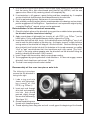
Function of the expanding
split rings
1. Slide the large split ring onto the small
i`ÊvÊÌ
iÊiÝÌiÃÊÃ
>vÌ°
2. Follow it by the cone washer, pointed
i`ÊwÀÃÌ]ÊÌÊÌ
iÊÃ
>vÌÊiÝÌÊÌÊÌ
iÊëÌÊ
ring.
3. Take this complete assembly and thread
it into the hole in the threaded end of the
/
>`i°
{°Ê ÃÊÞÕÊÃVÀiÜÊÌÊÌ}iÌ
iÀ]ÊÞÕÊÜÊvÀViÊ
the cone washer into the split ring. The
ëÌÊÀ}ÊÜÊLi}ÊÌÊiÝ«>`ÆÊVÌÕiÊ
screwing until the cone has disappeared
completely into the split ring. (See
figure 17.) *Use the split ring in the
orientation seen in figure 17. With the
cone washer clamping the split ring,
vÕÞÊiÝ«>`i`]Ê>}>ÃÌÊÌ
iÊy>}iÊvÊÌ
iÊ
iÝÌiÃÊÃ
>vÌÊÌ
iÊÌÊÃÊÀi>`ÞÊÌÊ`ÀÛiÊ
a bearing. When driving bearings, the
split ring should only be used in this fully
iÝ«>`i`Ê>`ÊV>«i`Ê«ÃÌ°
x°Ê ,ii>ÃiÊ LÞÊ ÕÃVÀiÜ}Ê Ì
iÊ iÝÌiÃÊ
}ÕÀiÊ£ÇÊÊvÕVÌÊvÊÌ
iÊëÌÊÀ}
Ã
>vÌÊ vÀÊ Ì
iÊ /
>`i°Ê Ê
iÊ ÃÊ
«ÀÛ`i`Ê Ê Ì
iÊ i`Ê vÊ Ì
iÊ iÝÌiÃÊ
Ã
>vÌÊvÀÊ>Ê{Ê
iÝÊiÞÊÊÌ
iÊiÛiÌÊÌÊ
>ÃÊLiViÊÌÊÌ}
ÌÊÌÊÌÕÀÊÜÌ
Êw}iÀð
Note: This tool set is designed only for working on Chris King hubs. It is not intended to be
ÕÃi`ÊÜÌ
Ê>ÞÊÌ
iÀÊ«>ÀÌÃÊÀÊÊ>ÞÊÌ
iÀÊ
ÕLðÊÊ1ÃiÊÌ
iÀÊÌ
>ÊÌ
>ÌÊvÀÊÜ
V
ÊÌÊÃÊÌi`i`Ê
may cause damage to the tool, other products, and/or bodily harm.
Front hubs
Disassembly of the front two piece axle hub
£°Ê ÃiÀÌÊxÊÊ
iÝÊÜÀiV
iÃÊÌÊLÌ
Êi`ÃÊvÊ>ÝiÊ>ÃÃiLÞ°Ê*Pro Tip: Use a bench vice
to hold one of the 5mm hex wrenches.
Ó°Ê `ÊivÌÊ
>`ÊÃÌ>Ì>ÀÞÊ>`ÊÌÕÀÊÀ}
ÌÊ
>`ÊVÕÌiÀVVÜÃiÊ£É{ÊÌÕÀÊÕÌÊ>ÃÃiLÞÊÃÊ
loose.
16
Rev. 12/12-A
Î°Ê ÃiÊ>`ÊÕÃVÀiÜÊ>`ÕÃÌ}ÊViÊ>`Ê>ÝiÊi`ÊÕÌÊÌ
iÞÊ>ÀiÊvÀiiÊvÀÊ>Ê>Ýi°
{°Ê -`iÊÕÌÊ>Ê>Ýi°
x°Ê Ì
Ê
ÕLÊÃ
iÊLi>À}Ê>ÃÃiLiÃÊV>ÊÜÊLiÊ>VViÃÃi`°
Disassembly of the front one piece axle hub
£°Ê ÃiÀÌÊ>ÊÓ°xÊ
iÝÊÜÀiV
ÊÌÊÌ
iÊ>`ÕÃÌ}ÊV>«Ê«V
ÊLÌ]Ê>`ÊÃi°
Ó°Ê 7Ì
Ê>`ÕÃÌ}ÊViÊv>V}ÊÌÜ>À`ÃÊÞÕ]Ê
`Ê««ÃÌiÊi`ÊvÊ>ÝiÊÃÌ>Ì>ÀÞ]Ê>`ÊÀÌ>ÌiÊ
ViÊÊ>ÊVÕÌiÀÊVVÜÃiÊ`ÀiVÌ°ÊvÌiÀÊiÊV«iÌiÊÀiÛÕÌÊÌ
iÊ>`ÕÃÌ}ÊViÊ
Ã
Õ`ÊLiÊvÀiiÊvÀÊÌ
iÊ>Ýi°ÊvÊ>`ÕÃÌ}ÊV>«ÊÃÊ`vwVÕÌÊÌÊÃi]ÊÃiÀÌÊ>ÊÓ°xÊ
iÝÊ
iÞÊÌʺ
i«iÀÊ
i»ÊÊ>`ÕÃÌ}ÊV>«Ê>`>ViÌÊÌÊÓ°xÊ
iÝÊLÌ°Ê1ÃiÊÌ
iÊ
iÝÊiÞÊ>ÃÊ
a lever to loosen adjusting clamp.
Î°Ê -`iÊÕÌÊ>Ýi°
{°Ê Ì
Ê
ÕLÊÃ
iÊLi>À}Ê>ÃÃiLiÃÊV>ÊÜÊLiÊ>VViÃÃi`
Removal of
the bearings:
Classic & ISO
SD Hubs
£°Ê -iÌÕ«Ê iÝÌiÃÊ
shaft by placing
Ã>Ê iÝ«>`}Ê
ëÌÀ}]ÊL}Êi`Ê
first, on the small
threaded end
followed by cone
washer, tapered
end facing split
}ÕÀiÊ£nÊÊÀiÛiÊvÀÌÊ
ÕLÊÃ
iÊLi>À}
ring.
2. W h i l e k e e p i n g
iÝÌiÃÊ Ã
>vÌÊ
vÀÊÀÌ>Ì}]ÊvÕÞÊiÝ«>`ÊÃ>ÊiÝ«>`}ÊëÌÀ}ÊLÞÊÌÕÀ}ÊÌ
iÊ/
>`i°Ê-iiÊw}ÕÀiÊ
18.)
Î°Ê *ÕÃ
ÊÕÀi`ÊÀ}ÊyÕÃ
ÊÜÌ
Ê
ÕLÊÃ
i°ÊÊ/
ÃÊÜÊ«ÃÌÊÌ
iÊëÌÀ}Ê`ÀiVÌÞÊLi
`ÊÌ
iÊ
bearing.
4. Capture bearing by threading knurled ring until it is snug against hub shell.
x°Ê 1Ã}Ê>Ê>iÌÊÀÊL>Ê«iiÊ
>iÀ]ÊÌ>«Ê/
>`iÊÌÊÀiÛiÊLi>À}ÊvÀÊÌ
iÊ
ÕLÊÃ
i°
6. Withdraw tool and, if necessary, repeat for the other side.
Removal of the bearings: ISO LD Hubs
£°Ê -`iÊiÊvÊÌ
iÊÃÕ««i`ÊÊÕ`iÊLÕÃ
}ÃÊÌÊÌ
iÊ/>`iÊÜÌ
ÊÌ
iÊÃ>iÀÊÃ`iÊv>V}Ê
the threaded portion, until it sits flush with the thrust collar.
Ó°Ê -iÌÕ«Ê iÝÌiÃÊ Ã
>vÌÊ LÞÊ «>V}Ê Ì
iÊ ,i`Ê >À}iÊ Ã«ÌÀ}]Ê Ê Ì
iÊ Ã>Ê Ì
Ài>`i`Ê i`Ê
followed by cone washer, tapered end facing split ring.
Î°Ê ÃiÀÌÊ/
>`iÊÌ
ÀÕ}
ÊiÊÃ`iÊvÊ
ÕLÊÃ
iÊÕÌÊÌ
Ài>`i`Êi`ÊÃ
Üð
{°ÊÊÊ/
Ài>`ÊiÝÌiÃÊÃ
>vÌÊÌÊ/
>`iÊÜÌ
ÕÌÊiÝ«>`}ÊëÌÀ}°
x°Ê *ÃÌÊÌ
iÊ,i`Ê>À}iÊ-«Ì,}ÊLi
`ÊÌ
iÊLi>À}ÊÞÕÊÜÃ
ÊÌÊÀiÛi]ÊÛiÀÌÊÌ
iÊ/>`iÊ
Rev. 12/12-A
17
ÃÊÌ
>ÌÊÌ
iÊLi>À}ÊÀiÃÌÃÊÊÌ
iÊëÌÀ}°Ê/«\ÊÜ
iÊÀiÛ}ÊLÌ
ÊLi>À}ÃÊÌÊÃÊLiÃÌÊÌÊ
first remove the disc side bearing.)
È°Ê Ý«>`ÊÌ
iÊ,i`Ê>À}iÊ-«Ì,}ÊLÞÊÌÕÀ}ÊÌ
iÊÕÀi`Êi`ÊvÊÌ
iÊiÝÌiÃÊÃ
>vÌÊVVÜÃi°Ê
ÕLiÊ V
iVÊ Ì
iÊ Ã«ÌÀ}ÃÊ ÀiÌ>ÌÊ ÌÊ iÃÕÀiÊ ÌÊ ÃÊ vÕÞÊ iÝ«>`i`Ê >`Ê Li
`Ê Ì
iÊ
Li>À}°Ê9ÕÊ>ÞÊÃiÀÌÊ>Ê{Ê
iÝÊiÞÊÌÊÌ
iÊiÝÌiÃÊÃ
>vÌÊÌÊiÃÕÀiÊÌ
iÊëÌÊÀ}ÊÃÊ
vÕÞÊiÝ«>`i`°®
Ç°Ê />iÊÌ
iÊÃiV`ÊÊÕ`iÊÕÃ
}Ê>`ÊÃ`iÊÌÊÌÊÌ
iÊiÝÌiÃÊÃ
>vÌÊÜÌ
ÊÌ
iÊÃ>iÀÊ
end inserting into the bearing’s inner race.
n°Ê >«ÌÕÀiÊLi>À}ÊLÞÊÌ
Ài>`}ÊÕÀi`ÊÀ}ÊÕÌÊÌÊÃÊÃÕ}Ê>}>ÃÌÊÌ
iÊÊÕ`iÊÕÃ
}]Ê
ÜÌ
ÊÌ
iÊ>ÃiÀ>Ài`ÊÃ`iÊv>V}Ê>Ü>ÞÊvÀÊÌ
iÊ
ÕL°
°Ê ÛiÀÌÊÌ
iÊÌÊÃÊÌ
>ÌÊÌ
iÊ
>`iÊÃÊÜÊv>V}ÊÕ«]Ê>Ü}ÊÌ
iÊwÀÃÌÊÊÕ`iÊLÕÃ
}ÊÌÊ
slide into the others bearing’s inner race.
£ä°Ê1Ã}Ê>Ê>iÌÊÀÊL>Ê«iiÊ
>iÀ]ÊÌ>«Ê/
>`i½ÃÊ-ÌÀiÀÊ«>ÌiÊÌÊÀiÛiÊLi>À}ÊvÀÊ
the hub shell.
££°Ê7Ì
`À>ÜÊÌÊ>`]ÊvÊiViÃÃ>ÀÞ]ÊÀi«i>ÌÊvÀÊÌ
iÊÌ
iÀÊÃ`i]Ê>ÜÊÌ
iÊÊÕ`iÊÕÃ
}ÊÌÊ
take the place of the bearing that was removed.
Service of the bearings
ÊvÊÌ
iÊLi>À}ÃÊ>ÀiÊÃÌ>iÃÃÊÃÌii]ÊÃÊÃ
ÀÌÊÌiÀÊÜ>ÌiÀÊÌÀÕÃÊÃ
Õ`ÊÌÊi>`ÊÌÊ>ÞÊ
substantial damage. Judging when to service the bearings is completely dependent on the
riding style and conditions.
1. Chris King sealed bearings have removable snap rings that hold the rubber seals in place.
2. Carefully, using a small screwdriver, pick, or penknife, remove the snap ring by inserting
tool into split of snap ring. Gently work one end of the snap ring toward bearing center until
it is out of its groove. Follow the ring around with the tool until the snap ring is completely
dislodged.
Î°Ê vÌÊ>`ÊÀiÛiÊiÝ«Ãi`ÊÀÕLLiÀÊÃi>ÊÌÊ>VViÃÃÊÌ
iÊÌiÀÀÊvÊÌ
iÊLi>À}°
{°Ê /
ÀÕ}
ÞÊyÕÃ
ÊÌ
iÊLi>À}ÊÜÌ
Ê>Ê}
ÌÊëÀ>ÞÊÕLÀV>ÌÊi°}°Ê7{ä™) and use an air
compressor to blow dry.
x°Ê 7«iÊ`ÀÌÊ>`ÊÌ
iÀÊVÌ>>ÌÃÊvÀÊÌ
iÊÃi>ÃÊ>`ÊÃ>«ÊÀ}ðÊÛ`ÊVi>}ÊÌ
iÊÃi>ÃÊ
with solvent, which could cause deterioration.
"/\Ê-iÊÃÛiÌÃ]ÊÃÞÌ
iÌVÊÕLÀV>ÌÃ]Ê>`Ê}Ài>ÃiÃÊÜÌ
Ê
}
«ÀiÃÃÕÀiÊ>``ÌÛiÃÊ>ÞÊ>ÌÌ>VÊ
>`Ê`>>}iÊÃi>ÃÊ>`ÊÌ
iÀÊiÌ>VÊ>ÌiÀ>ðÊâiÊiÝ«ÃÕÀiÊÌÊÌ
iÃiÊÃÕLÃÌ>ViÃÊ>`Ê
Ì
ÀÕ}
ÞÊ`ÀÞÊ
ÕLÊ>vÌiÀÊVi>}°ÊÛ`ÊÕÃ}ÊVÕ>ÃÌVÊVi>iÀÃÊ>`ÊVÌÀÕÃÌÊL>Ãi`Ê`iÌiÀ}iÌðÊÊ
È°Ê >ÞÊ>ÊLi>`ÊvÊÕÀÊ,}ÀÛi™ grease, filling the gap between the inner and outer races 3/4
Ì
iÊÜ>ÞÊ>ÀÕ`ÊLi>À}°ÊÊ,Ì>ÌiÊÌ
iÊiÀÊÀ>ViÊÌÊÜÀÊ}Ài>ÃiÊÌ
ÀÕ}
ÕÌÊÌ
iÊL>Ê>Ài>°
Ç°Ê ,i«>ViÊÀÕLLiÀÊÃi>ÊLiÌÜiiÊiÀÊ>`ÊÕÌiÀÊLi>À}ÊÀ>Vi°
8. Insert one edge of snap ring into groove of outer bearing race. Press along entire groove
until snap ring is fully seated; a small gap should be visible between both ends of the snap
ring.
9. Turn inner race of bearing by hand to test for binding. If bearings do not run smooth, repeat
ÃÌi«ÃÊ£°Ê`}ÊÃÊvÌiÊ>ÊÀiÃÕÌÊvÊ«À«iÀÞÊÃi>Ìi`ÊÃi>ÃÊ>`ÉÀÊÃ>«ÊÀ}ð
1Ãi`ÊÃ>«ÊÀ}ÃÊ>`ÊÃi>ÃÊV>ÊLiÊÀiÃÌ>i`ÊÕiÃÃÊÜ>À«i`]Ê«ÕVÌÕÀi`]ÊÀÊÌ
iÀÜÃiÊ`>>}i`°Ê
If damaged, replacement seals and snap rings are available from your local bike shop or directly
18
Rev. 12/12-A
from Chris King precision components.
Reinstallation of the
bearings: Classic &
ISO SD Hubs
1. Insert small inner seal into
bearing bore. On ISO hubs
install the disc side bearing
first.
2. Place small hub bearing,
black seal side first, onto
L>ÀiÊ/
>`i°
3. Insert knurled ring, small
end first, into opposite side
}ÕÀiÊ£ÊÊ«ÀiÃÃÊvÀÌÊ
ÕLÊÃ
iÊLi>À}Ã
of hub shell.
{°Ê *>ÃÃÊ/
>`iÊÜÌ
ÊLi>À}Ê
Ì
ÀÕ}
ÊÃÌ>>ÌÊÃ`iÊvÊ
ÕLÊÃ
iÊ>`ÊÌ
Ài>`ÊÌÊÕÀi`ÊÀ}°ÊÊ
ÌÕiÊÌÕÀ}Ê/
>`iÊ
ÌÊ«ÀiÃÃÊLi>À}ÊÕÌÊÌÊÃÊwÀÞÊÃi>Ìi`°ÊÊ-iiÊw}ÕÀiÊ£°®ÊÊÃiÊ/
>`i]ÊÌÕÀÊÕÀi`Ê
À}Ê£näcÊ>`ÊÌ}
ÌiÊ/
>`iÊÌÊ«ÀiÃÃÊLi>À}Ê>}>°ÊÊ/
ÃÊ>ÃÃÕÀiÃÊÌ
iÊLi>À}ÊÃÊÃi>Ìi`Ê
flatly.)
5. Withdraw tool and, if necessary, repeat for the other side.
Reinstallation of the bearings: ISO LD Hubs
£°Ê ÃiÀÌÊÊÕLÊiÀÊÃi>ÊÌÊÌ
iÊ
ÕLÃ
i½ÃÊLi>À}ÊLÀi°
Ó°Ê -`iÊÊÕ`iÊÕÃ
}ÊÌÊÌ
iÊ/>`iÊyÕÃ
ÊÜÌ
ÊÌ
iÊÌ
ÀÕÃÌÊV>ÀÊÜÌ
ÊÌ
iÊ>À}iÀÊÃ`iÊ
against the thrust collar.
ÎÊ Ê*>ViÊÌ
iÊÃi>i`ÊÊ
ÕLÊLi>À}]ÊÃi>ÉÃ>«À}ÊÃ`iÊv>V}ÊÌ
iÊÊÕ`iÊLÕÃ
}ÊÊÌ
iÊ
/>`i°
Î°Ê ÃiÀÌÊÌ
iÊÃ>Êi`ÊvÊÌ
iÊÊÕ`iÊÕÃ
}Ê>}ÊÜÌ
ÊÕÀi`ÊÀ}]ÊÜÌ
ÊÌ
iÊ>ÃiÀÊ>Ài`Ê
side facing in, into opposite side of hub shell.
{°Ê *>ÃÃÊ/
>`iÊÜÌ
ÊLi>À}ÊÌ
ÀÕ}
ÊÃÌ>>ÌÊÃ`iÊvÊ
ÕLÊÃ
iÊ>`ÊÌ
Ài>`ÊÌÊÕÀi`ÊÀ}°ÊÊ
ÌÕiÊÌÕÀ}Ê/
>`iÊÌÊ«ÀiÃÃÊLi>À}ÊÕÌÊÌÊÃÊwÀÞÊÃi>Ìi`°ÊÃiÊ/
>`i]ÊÌÕÀÊ
ÕÀi`ÊÀ}Ê£näcÊ>`ÊÌ}
ÌiÊ/
>`iÊÌÊ«ÀiÃÃÊLi>À}Ê>}>°ÊÊ/
ÃÊ>ÃÃÕÀiÃÊÌ
iÊLi>À}Ê
is seated flat)
5. Withdraw tool and, if necessary, repeat for the other side.
Reassembly of the front two piece axle
hub
£°Ê ÕLÀV>ÌiÊ Ì
iÊ >Ê >ÝiÊ À}ÃÊ ÜÌ
Ê }
ÌÜi}
Ì]Ê ÜÊ
ÛÃVÃÌÞÊ]ÊÜÌ
Ê*/ÊÊi°}°Ê/ÀÜÊ™).
Ó°Ê ÃiÀÌÊ>Ê>ÝiÊÌÊ
ÕLÊÃ
i°Ê"iÊ-"Ê>`Ê1Ê
ÕLÃÊ
ÃiÀÌÊ>ÝiÊvÀÊÌ
iÊ`ÃVÊÃ`i°Ê
3. Lightly grease threads on the adjusting cone.
{°Ê /
Ài>`Ê>`ÕÃÌ}ÊViÊ>}Ê>ÝiÊi`ÊÕÌÊ>ÊÃ>Ê}>«Ê>ÌÊ
the beginning of the threads shows. (See figure 20.)
Rev. 12/12-A
19
}ÕÀiÊÓäÊÊ>`ÕÃÌ}ÊVi
x°Ê
È°Ê
Ç°Ê
n°Ê
/
Ài>`Ê>ÝiÊi`Ê>`Ê>`ÕÃÌ}ÊViÊÌÊÌ
iÊ«ÀÌÀÕ`}ÊÌ
Ài>`ÃÊvÊ>Ê>Ýi°
}
ÌÞÊÃÕ}Ê>ÝiÊi`Ê>`Ê>`ÕÃÌ}ÊViÊÕ«ÊÌÊLi>À}°
/
Ài>`Ê>ÝiÊi`ÊÌÊ>`ÕÃÌ}ÊViÊÕÌÊÌÊÃ̫ð
*ÀVii`ÊÌʺ`ÕÃÌiÌÊvÊÌ
iÊvÀÌʵÕVÀii>ÃiÊ
ÕL»ÊLiÜ®°
Reassembly of the front one piece axle hub
£°Ê
Ó°Ê
3.
{°Ê
ÃiÀÌÊ>Ê>ÝiÊÌÊ
ÕLÊÃ
i°
/
Ài>`Ê>`ÕÃÌ}ÊV>«ÊÌÊÌ
iÊ«ÀÌÀÕ`}ÊÌ
Ài>`ÃÊvÊ>Ýi°
Snug adjusting cone up to bearing.
*ÀVii`ÊÌʺ`ÕÃÌiÌÊvÊÌ
iÊvÀÌÊLÌÊ
ÕL»ÊLiÜ®°
Adjustment of the front two piece axle hub
£°Ê ÃiÀÌÊxÊÊ
iÝÊÜÀiV
iÃÊÌÊLÌ
Êi`ÃÊvÊ>ÝiÊ>ÃÃiLÞ°Ê*Pro Tip: Use a bench vice
to hold one of the 5mm hex wrenches.
Ó°Ê `ÊivÌÊ
>`ÊÃÌ>Ì>ÀÞÊ>`ÊÌÕÀÊÀ}
ÌÊ
>`ÊVÕÌiÀVVÜÃiÊ£É{ÊÌÕÀÊÕÌÊ>ÃÃiLÞÊÃÊ
loose.
Î°Ê `Ê
iÝÊÜÀiV
iÃÊÃÌ>Ì>ÀÞÊ>`Ê>`ÕÃÌÊLi>À}Ê«Ài>`ÊÜÌ
Ê>`ÕÃÌ}ÊVi°
{°Ê `Û>ViÊ>`ÕÃÌ}ÊViÊÕÌÊÌÊÕÃÌÊVÌ>VÌÃÊLi>À}]ÊÌ
iÊL>VÊvvÊ>««ÀÝ>ÌiÞʣɣÈÊ
turn.
x°Ê "ViÊ«Ài>`ÊÃÊÃiÌ]ÊÌ}
ÌiÊ>ÝiÊ>ÃÃiLÞÊÌÊ££äÊ°LÊÀÊ£Ó°{ °
È°Ê ÕLiÊV
iVÊ>`ÕÃÌiÌÊLÞÊV>«}ÊÜ
iiÊÌÊvÀÊÜÌ
ʵÕVÀii>Ãi°ÊÊ
iVÊvÀÊ«>ÞÊ
or binding, and readjust if needed.
Adjustment of the front one piece axle hub
£°Ê ÀÌÊ LÌÊ
ÕLÃÊ vi>ÌÕÀiÊ Ã«iV>Ê >`ÕÃÌ}Ê V>«ÃÊ Ü
V
Ê âiÊ ÛiÀÊ Ì}
Ìi}Ê ÀÊ
over preloading of the bearings. Normal adjustment is accomplished by finger tightening
>`ÕÃÌ}ÊÀ}ÊÌÊ>ÝiÊÕÌÊÌÊÃÌ«ÃÊ>}>ÃÌÊLi>À}°
Ó°Ê "ViÊ>`ÕÃÌ}ÊV>«ÊÃÊÊ«ÃÌ]ÊÌ}
ÌiÊ>`ÕÃÌ}ÊÀ}Ê«V
ÊLÌÊÌÊ£äÊ°LÊÀÊ£°£Î °
Î°Ê ÕLiÊV
iVÊ>`ÕÃÌiÌÊLÞÊLÌ}ÊÜ
iiÊÌÊvÀ°Ê
iVÊvÀÊ«>ÞÊÀÊL`}]Ê>`ÊÀi>`ÕÃÌÊ
vÊii`i`°Ê`ÕÃÌiÌÊ>ÞÊLiÊ>VV«Ã
i`ÊÜ
iÊLÌi`ÊÌÊvÀ°
20
Rev. 12/12-A
Rear hubs
Disassembly of the rear two piece axle hub
The following instructions assume that the drive shell is facing to the right:
£°Ê ,iÛiÊV>ÃÃiÌÌiÊ«iÀÊ>Õv>VÌÕÀiÀ½ÃÊÃÌÀÕVÌð
Ó°Ê ÃiÀÌÊxÊÊ
iÝÊÜÀiV
iÃÊÌÊ
LÌ
Ê i`ÃÊ vÊ >ÝiÊ >ÃÃiLÞ°Ê
(See figure 21.) *Pro Tip: Use
a bench vice to hold one of
the 5mm hex wrenches.
Î°Ê `Ê ivÌÊ
>`Ê ÃÌ>Ì>ÀÞÊ
and turn right hand
counterclockwise 1/4 turn
until assembly is loose.
4. Loosen and unscrew adjusting
ViÊ >`Ê >ÝiÊ i`Ê ÕÌÊ Ì
iÞÊ
>ÀiÊvÀiiÊvÀÊÌ
iÊ>Ê>Ýi°
}ÕÀiÊÓ£ÊÊ`Ã>ÃÃiLiÊ>Ê>Ýi
x°Ê ,iÛiÊ>Ê>ÝiÊLÞÊ«Õ}Ê
Ê`ÀÛiÊÃ`iÊi`ÊvÊ>Ê>Ýi°
È°Ê `Ê
ÕLÊÀÊÜ
iiÊÊiÊ
>`Ê>`Ê«ÕÊ`ÀÛiÃ
iÊÕÌÊÜÌ
ÊÌ
iÊÌ
iÀ°ÊÊ
Ç°Ê Ì
Ê
ÕLÊÃ
iÊ>`Ê`ÀÛiÊÃ
iÊLi>À}Ê>ÃÃiLiÃÊV>ÊÜÊLiÊ>VViÃÃi`°ÊÊ
Disassembly of the rear one piece axle hub
The following instructions assume that the drive shell is facing to the right:
£°Ê ,iÛiÊV>ÃÃiÌÌiÊ«iÀÊ>Õv>VÌÕÀiÀ½ÃÊÃÌÀÕVÌð
Ó°Ê ÃiÀÌÊ>ÊÓ°xÊ
iÝÊÜÀiV
ÊÌÊ>`ÕÃÌ}ÊV>«Ê«V
ÊLÌ]Ê>`ÊÃi°
Î°Ê 7Ì
Ê>`ÕÃÌ}ÊV>«Êv>V}ÊÌÜ>À`ÃÊÞÕ]Ê
`Ê««ÃÌiÊi`ÊvÊ>ÝiÊÃÌ>Ì>ÀÞ]Ê>`ÊÀÌ>ÌiÊ
ViÊÊ>ÊVÕÌiÀÊVVÜÃiÊ`ÀiVÌ°ÊvÌiÀÊiÊV«iÌiÊÀiÛÕÌÊÌ
iÊ>`ÕÃÌ}ÊViÊ
Ã
Õ`ÊLiÊvÀiiÊvÀÊÌ
iÊ>Ýi°ÊvÊ>`ÕÃÌ}ÊV>«ÊÃÊ`vwVÕÌÊÌÊ«ÃÌ]ÊÃiÀÌÊ>ÊÓ°xÊ
iÝÊ
iÞÊÌʺ
i«iÀÊ
i»ÊÊ>`ÕÃÌ}ÊV>«Ê>`>ViÌÊÌÊÓ°xÊ
iÝÊLÌ°Ê1ÃiÊÌ
iÊ
iÝÊiÞÊ>ÃÊ
a lever to loosen adjusting clamp
{°Ê -`iÊÕÌÊ>Ýi°
xÊ `Ê
ÕLÊÀÊÜ
iiÊÊiÊ
>`Ê>`Ê«ÕÊ`ÀÛiÃ
iÊÜÌ
ÊÌ
iÀ°ÊÊ
È°Ê Ì
Ê
ÕLÊÃ
iÊ>`Ê`ÀÛiÃ
iÊLi>À}Ê>ÃÃiLiÃÊV>ÊÜÊLiÊ>VViÃÃi`°ÊÊÊÊ
Removal of the non-drive side hub bearing
£°Ê -iÌÕ«Ê iÝÌiÃÊ Ã
>vÌÊ LÞÊ «>V}Ê Ã>Ê iÝ«>`}Ê Ã«ÌÀ}]Ê L}Ê i`Ê wÀÃÌ]Ê Ê Ì
iÊ Ã>Ê
threaded end followed by cone washer, tapered end facing split ring.
Ó°Ê ÃiÀÌÊ/
>`iÊÌ
ÀÕ}
Ê>À}iÊÃ`iÊvÊÌ
iÊ
ÕLÊÃ
iÊÕÌÊÌ
Ài>`i`Êi`ÊÃ
Üð
Î°Ê /
Ài>`ÊiÝÌiÃÊÃ
>vÌÊÌÊ/
>`iÊÜÌ
ÕÌÊiÝ«>`}ÊëÌÀ}°
{°Ê *ÃÌÊÌ
iÊëÌÀ}Ê`ÀiVÌÞÊLi
`ÊÌ
iÊLi>À}°
«iÌiÞÊÌ
Ài>`ÊÕÀi`ÊÀ}]ÊÃ>Êi`Ê
wÀÃÌ]ÊÌ
iÊ>ÃiÀÊ>ÀÊv>V}ÊÕÌÜ>À`]ÊÌÊÌ
iÊiÝÌiÃÊÃ
>vÌ]ÊÌ
iÊL>VÊvvÊiÝ>VÌÞÊ£ÉÓÊÌÕÀ°
x°Ê 7
iÊ ii«}Ê iÝÌiÃÊ Ã
>vÌÊ vÀÊ ÀÌ>Ì}]Ê vÕÞÊ iÝ«>`Ê Ã>Ê iÝ«>`}Ê Ã«ÌÀ}Ê LÞÊ
ÌÕÀ}Ê/
>`i°
6. Capture bearing by advancing knurled ring until it is snug against hub shell.
Rev. 12/12-A
21
Ç°Ê 1Ã}Ê>ÊL>Ê«iiÊ
>iÀ]Ê
Ì>«Ê /
>`iÊ ÌÊ ÀiÛiÊ
bearing from hub shell.
(See figure 22.)
Removal of
the RingDrive™
mechanism and drive
side bearing
£°Ê -iÌÕ«Ê iÝÌiÃÊ Ã
>vÌÊ LÞÊ
«>V}Ê >À}iÊ iÝ«>`}Ê
ëÌÀ}Ê Ê Ì
iÊ Ã>Ê
}ÕÀiÊÓÓÊÊÀiÛiÊ`ÀÛiÊÃ`iÊLi>À}
threaded end followed by
cone washer, tapered end
facing split ring. *If the
non-drive side bearing has
already been removed,
slide driveshell bushing
tool on to T-handle with
the wide side facing the
thrust collar.
Ó°Ê ÃiÀÌÊ/
>`iÊÌ
ÀÕ}
ÊÌ
iÊ
`ÀÛiÊ Ã`iÊ vÊ Ì
iÊ
ÕLÊ
Ã
iÊÕÌÊÌÊiÝÌi`ÃÊLiÞ`Ê
the other side.
{°Ê /
Ài>`ÊiÝÌiÃÊÃ
>vÌÊÊÌÊ
/
>`iÊÜÌ
ÕÌÊiÝ«>`}Ê
ëÌÀ}°
5. Pull assembled tool towards
}ÕÀiÊÓÎÊÊV>«ÌÕÀiÊÜ
iÊ,}ÀÛi™ assembly
`ÀÛiÊÃ`iÊÕÌÊÕÀi`Ê
ring is bottomed in drive
side bearing.
È°Ê 7
iÊii«}ÊÌ
iÊiÝÌiÃÊ
shaft from rotating, rotate
/
>`iÊÌÊvÕÞÊiÝ«>`ÊÌ
iÊ
>À}iÊ iÝ«>`}Ê Ã«ÌÀ}Ê
behind the spring retainer.
(See figure 23.)
7. Lightly push tool towards
the driveside until it stops,
then thread knurled ring
with the laser mark facing
}ÕÀiÊÓ{ÊÊÀiÛiÊ,}ÀÛi™ assembly
ÕÌÜ>À`°Ê ,Ì>ÌiÊ ÕÀi`Ê
ring until it again bottoms on
Ì
iÊ`ÀÛiÃ`iÊLi>À}°ÊÊ/
ÃÊÜÊV>«ÌÕÀiÊ>Ê,}ÀÛi™ parts and bearing on the tool as
they are removed from the hub shell.) *Never attempt to remove the driveside bearing
independantly of the RingDrive™ internals.
22
Rev. 12/12-A
n°Ê 1Ã}Ê>Ê>iÌ]ÊÌ>«ÊÃÌÀiÊ«>ÌiÊÌÊ`Ã`}iÊ,}ÀÛi™ and bearing from hub shell. (See
figure 24 on the previous page.)
Disassembly of the driveshell assembly
£°Ê >iÊÃÕÀiÊÌ
>ÌÊÌ
iÊ/>`iÊ`ÀÛiÃ
iÊLÕÃ
}ÊÃÌ>i`ÊÜÌ
ÊÌ
iÊÜ`iÊÃ`iÊv>V}ÊÌ
iÊÌ
ÀÕÃÌÊ
collar.
Ó°ÊÊ ,iÛiÊ>ÝiÊLÞÊ«Õ}ÊÌÊÕÌÊvÀÊÌ
iÊÃi>ÊÃ`iÊvÊÌ
iÊ`ÀÛiÃ
i°
Î°Ê 1ÃiÊV}ÊëiÊÜÀiV
ÊÌÊ
`Ê`ÀÛiÃ
iÊÊÛÃi°
{°Ê 1ÃVÀiÜÊÃi>ÊÀ}ÊÜÌ
ÊëiÊ`ÀÛiÀ°
x°Ê ,iÛiÊV>«ÌÕÀiÊ«>ÌiÊ>`Êii`iÊLi>À}ÊV>}i°
È°Ê -iÌÕ«Ê iÝÌiÃÊ Ã
>vÌÊ LÞÊ «>V}Ê Ã>Ê iÝ«>`}Ê Ã«ÌÀ}]Ê L}Ê i`Ê wÀÃÌ]Ê Ê Ì
iÊ Ã>Ê
Ì
Ài>`i`Êi`ÊvÜi`ÊLÞÊViÊÜ>Ã
iÀ]ÊÌ>«iÀi`Êi`Êv>V}ÊëÌÀ}°
Ç°Ê ÃiÀÌÊÌ
iÊ/
>`iÊÌ
ÀÕ}
Ê`ÀÛiÃ
iÊvÀÊÌ
iÊ
iV>Êëi`Êi`°
n°Ê /
Ài>`ÊiÝÌiÃÊÃ
>vÌÊÌÊ/
>`iÊÜÌ
ÕÌÊiÝ«>`}ÊëÌÀ}°
9. Slide driveshell up
against knurled
r i n g to position
Ì
iÊ Ã«ÌÀ}Ê ÕÃÌÊ
behind the bearing;
thread knurled ring
with the laser mark
facing inward on to
the opposite end
vÊ iÝÌiÃÊ Ã
>vÌÊ
iÝ>VÌÞÊÓ£ÉÓÊÌÕÀðÊ
The step on the ring
will center the end
of the driveshell.
}ÕÀiÊÓxÊÊÀiÛiÊ`ÀÛiÊÃ
iÊLi>À}
£ä°Ê`}Ê iÝÌiÃÊ
shaft stationary,
ÃVÀiÜÊ/
>`iÊÌÊ
iÝÌiÃÊÃ
>vÌÊÌÊvÕÞÊiÝ«>`ÊëÌÀ}°ÊÊ/
iÊÃ`iÊÌÊÕ«Ê>}>ÃÌÊÌ
iÊLi>À}Ê>`Ê>`Û>ViÊ
knurled ring to hold everything snug. (See figure 25.)
££°Ê`Ê Ì
iÊ />`iÊ Ü
iÊ ÌÕÀ}Ê Ì
iÊ ÕÀi`Ê À}Ê VVÜÃiÊ ÕÌÊ Ì
iÊ ÌiÀ>ÃÊ LiViÊ
dislodged. *If the press seems tight or when removing the internals from a stainless
steel driveshell it may be necessary to use a ball peen hammer to apply several blows
to the strike plate.
Disassembly of the BMX driveshell assembly
£°Ê ,iÛiÊ>ÝiÊvÀÊ`ÀÛiÃ
i°
Ó°Ê 1ÃiÊV}ÊëiÊÜÀiV
ÊÌÊ
`Ê`ÀÛiÃ
i]Ê
iV>ÊëiÊÃ`iÊÕ«]ÊÊÛÃi°
Î°Ê -iÌÊÕ«ÊiÝÌiÃÊÃ
>vÌÊLÞÊ«>V}ÊÃ>ÊiÝ«>`}ÊëÌÀ}]ÊL}Êi`ÊwÀÃÌ]ÊÊÌ
iÊÃ>Ê
threaded end followed by cone washer, tapered end facing split ring.
4. Thread knurled ring with the laser marked side facing inward completely on to the opposite
i`ÊvÊiÝÌiÃÊÃ
>vÌ°
x°Ê ÃiÀÌÊ/
>`iÊÌ
ÀÕ}
Ê`ÀÛiÃ
iÊvÀÊÌ
iÊ
iV>Êëi`Êi`Ê«>ÃÌÊÌ
iÊ8Êii`iÊLi>À}ðÊ
È°Ê /
Ài>`ÊiÝÌiÃÊÃ
>vÌÊÌÊ/
>`iÊÜÌ
ÕÌÊiÝ«>`}ÊëÌÀ}°
Ç°Ê -`iÊ`ÀÛiÃ
iÊÕ«Ê>}>ÃÌÊÕÀi`ÊÀ}ÊÌÊ«ÃÌÊÌ
iÊëÌÀ}ÊÕÃÌÊLi
`ÊÌ
iÊLi>À}ÆÊ
Rev. 12/12-A
23
the step on the ring will center the end of the driveshell.
n°Ê `}ÊÌ
iÊiÝÌiÃÊÃ
>vÌÊÃÌ>Ì>ÀÞ]ÊÃVÀiÜÊ/
>`iÊÌÊiÝÌiÃÊÃ
>vÌÊÌÊvÕÞÊiÝ«>`Ê
ëÌÀ}°ÊÊ/
iÊÃ`iÊÌÊÕ«Ê>}>ÃÌÊLi>À}Ê>`Ê>`Û>ViÊÕÀi`ÊÀ}ÊÌÊ
`ÊiÛiÀÞÌ
}Ê
snug.
°Ê `Ê Ì
iÊ />`iÊ Ü
iÊ ÌÕÀ}Ê Ì
iÊ ÕÀi`Ê À}Ê VVÜÃiÊ ÕÌÊ Ì
iÊ ÌiÀ>ÃÊ LiViÊ
dislodged. *If the press seems tight it may be necessary to use a ball peen hammer.
to apply several blows to the strike plate.
£ä°Ê,iÛiÊiÝÌiÃÊÃ
>vÌÊÌÊÀiÛiÊÌ°
Removal of BMX needle bearing
£°Ê
2.
3.
{°Ê
-`iÊ`ÀÛiÃ
iÊLÕÃ
}]ÊL}Êi`ÊwÀÃÌ]ÊÌÊÃ
>vÌÊvÊ/
>`i°
Slide driveshell, needle bearing end first, onto shaft.
Thread knurled ring, small end first, onto shaft.
ÌÕiÊ Ì
Ài>`}Ê /
>`iÊ ÌÊ ÕÀi`Ê À}Ê ÌÊ «ÕÃ
Ê ii`iÊ ÌÊ ViÌiÀÊ vÊ `ÀÛiÃ
i°ÊÊ
vÌiÀÊÌ
iÊLi>À}ÊÛiÃÊ>LÕÌÊ£ÉÓ»]ÊÌÊÃ
Õ`ÊLiViÊvÀiiÊÌÊÛiÊ>ÊÌ
iÊÜ>ÞÊÌ
ÀÕ}
Ê
the driveshell.
Service of the bearings
We offer our bearings with either quality steel or ceramic balls, so short term water intrusion
should not lead to any substantial damage. Judging when to service the bearings is completely
dependent on the riding style and conditions
1. Chris King sealed bearings have removable snap
rings that hold the rubber seals in place.
2. Carefully, using a small screwdriver, pick, or
penknife, remove the snap ring by inserting tool
into split of snap ring. Gently work one end of the
snap ring toward bearing center until it is out of its
groove. Follow the ring around with the tool until
the snap ring is completely dislodged. (see figure
26.)
Î°Ê vÌÊ>`ÊÀiÛiÊiÝ«Ãi`ÊÀÕLLiÀÊÃi>ÊÌÊ>VViÃÃÊÌ
iÊ
interior of the bearing.
4. Thoroughly flush the bearing with a light spray
ÕLÀV>ÌÊi°}°Ê7{ä™) and blow dry with an air
compressor.
5. Wipe dirt and other contaminants from the seals
>`Ê Ã>«Ê À}Ã°Ê Û`Ê Vi>}Ê Ì
iÊ Ãi>ÃÊ ÜÌ
Ê
solvent, which could cause deterioration.
}ÕÀiÊÓÈÊÊÀiÛiÊÃ>«ÊÀ}
"/\Ê-iÊÃÛiÌÃ]ÊÃÞÌ
iÌVÊÕLÀV>ÌÃ]Ê>`Ê}Ài>ÃiÃÊÜÌ
Ê
}
«ÀiÃÃÕÀiÊ>``ÌÛiÃÊ>ÞÊ>ÌÌ>VÊ
>`Ê`>>}iÊÃi>ÃÊ>`ÊÌ
iÀÊiÌ>VÊ>ÌiÀ>ðÊâiÊiÝ«ÃÕÀiÊÌÊÌ
iÃiÊÃÕLÃÌ>ViÃÊ
>`ÊÌ
ÀÕ}
ÞÊ`ÀÞÊ
ÕLÊ>vÌiÀÊVi>}°ÊÛ`ÊÌ
iÊÕÃiÊvÊVÕ>ÃÌVÊ>`Ê>V`VÊ`i}Ài>ÃiÀÃÊiÊ
citrus cleaners.
È°Ê >ÞÊ>ÊLi>`ÊvÊÕÀÊ,}ÀÛi™ grease, filling the gap between the inner and outer races
24
Rev. 12/12-A
1/3 for steel balls or 1/4 for ceramic around the large bearing and 3/4 for steel or 1/3 for
ceramic around the small bearing. Then rotate the inner race to work grease throughout
the ball area.
Ç°Ê ,i«>ViÊÀÕLLiÀÊÃi>ÊLiÌÜiiÊiÀÊ>`ÊÕÌiÀÊLi>À}ÊÀ>Vi°
8. Insert one edge of snap ring into groove of outer bearing race. Press along entire groove
until snap ring is fully seated; a small gap should be visible between both ends of the snap
ring.
9. Turn inner race of bearing by hand to test for binding. If bearings do not run smooth, repeat
ÃÌi«ÃÊ£°Ê`}ÊÃÊvÌiÊ>ÊÀiÃÕÌÊvÊ«À«iÀÞÊÃi>Ìi`ÊÃi>ÃÊ>`ÉÀÊÃ>«ÊÀ}ð
*Used snap rings and seals can be reinstalled unless warped, punctured, or otherwise
damaged. If damaged, replacement seals and snap rings are available from your local
bike shop or directly from Chris King precision components.
Reinstallation of the RingDrive™ mechanism and
driveside bearing
£°Ê /
iÊ `ÀÛiÃ`iÊ >`>«ÌiÀÊ LÕÃ
}Ê Ã
Õ`Ê LiÊ Ê «>ViÊ LivÀiÊ
«ÀVii`}ÊÌÊÃÌ>ÊÌ
iÊ,}ÀÛi™ and bearing.
2. Insert spring retainer in hub shell with square stepped edge facing
ÕÌ°ÊÊ-iiÊw}ÕÀiÊÓn°®ÊÊ>iÊÃÕÀiÊÌ
iÊëÀ}ÊÀiÌ>iÀÊ
>ÃÊ>ÊÀ}Ê
installed before inserting. (See figure 27.)
3. Insert drive spring. (See figure 29.)
4. Insert drive ring with the teeth facing out. (See figure 30.)
}ÕÀiÊÓnÊÊëÀ}Ê
retainer
}ÕÀiÊÎäÊÊ`ÀÛiÊ
ring
}ÕÀiÊÓÊÊ`ÀÛiÊ
spring
}ÕÀiÊÓÇÊÊÀ}
}ÕÀiÊΣÊÊ`ÀÛiÊ
ring
x°Ê >ÞÊ>ÊLi>`ÊvÊ,}ÀÛi™ lube onto ratchet face of drive ring.
È°Ê ÃiÀÌÊ`ÀÛiÊÀ}ÊÌÊÌ
iÊ
ÕLÊÃ
iÊÜÌ
ÊÌ
iÊÌiiÌ
Êv>V}ÊÌ
iÊ`ÀÛiÊÀ}°ÊÊiÊÃÕÀiÊÌÊÕLÀV>ÌiÊ
Ì
iÊÀ}ÊÜÌ
Ê}
ÌÜi}
Ì]ÊÜÊÛÃVÃÌÞÊ]ÊÜÌ
Ê*/ÊÊi°}°Ê/ÀÜÊ ™). The splines on
the outside of driven ring will engage the matching splines of the hub shell as it is pushed
ÊÌÊiÝ«ÃiÊÌ
iÊLÀiÊvÀÊÌ
iÊLi>À}°ÊÊ-iiÊw}ÕÀiÊΣ°®
7. Place the inner seal in the bearing bore on top of driven ring.
Rev. 12/12-A
25
n°Ê ÃiÀÌÊ/
>`iÊÌÊ
ÕLÊÃ
iÊvÀÊ
`ÀÛiÊ Ã`iÊ ÕÌÊ ÌÊ ÃÊ LÌÌi`Ê
on hub shell.
9. Place large hub bearing, black
Ãi>Ê Ã`iÊ wÀÃÌ]Ê ÌÊ Ì
iÊ >ÃiÀÊ
side marked side of knurled ring.
/
Ài>`Ê ÌÊ /
>`i]Ê Li>À}Ê
facing in, until the bearing just starts
into the counterbore. Continue
LÞÊÌÕÀ}ÊÌ
iÊ/
>`iÊÌÊ«ÕÊÌ
iÊ
knurled ring and bearing into the
}ÕÀiÊÎÓÊÊ«ÀiÃÃÊ`ÀÛiÊÃ`iÊLi>À}
bore until firmly seated. (See figure
ÎÓ]ÊiÝÌÊ«>}i°®ÊÊÃiÊ/
>`i]Ê
turn knurled ring 180° on bearing
>`ÊÌ}
ÌiÊ/
>`iÊÌÊ«ÀiÃÃÊLi>À}Ê>}>°ÊÊ/
ÃÊ>ÃÃÕÀiÃÊÌ
iÊLi>À}ÊÃÊÃi>Ìi`Êy>ÌÞÊ
against the shoulder of the counterbore.)
£ä°Ê,iÛiÊÌ°
Reinstallation of the non-driveside bearing
1. Insert small inner seal into
`ÀÛiÃ`iÊLi>À}ÊLÀi°
2. Place small hub bearing,
black seal side first, onto
L>ÀiÊ/
>`i°
3. Insert knurled ring laser side
facign out, into driveside of
hub shell.
{°Ê *>ÃÃÊ/
>`iÊÜÌ
ÊLi>À}Ê
Ì
ÀÕ}
Ê`ÀÛiÃ`iÊvÊ
ÕLÊ
shell and thread into knurled
ring. Continue turning
/
>`iÊ ÌÊ «ÀiÃÃÊ Li>À}Ê
until it is firmly seated. (See
}ÕÀiÊÎÎÊÊÃÌ>Ê`ÀÛiÊÃ`iÊLi>À}
w}ÕÀiÊÎΰ®ÊÊÃiÊ/
>`i]Ê
turn knurled ring 180° and
Ì}
ÌiÊ/
>`iÊÌÊ«ÀiÃÃÊLi>À}Ê>}>°ÊÊ/
ÃÊ>ÃÃÕÀiÃÊÌ
iÊLi>À}ÊÃÊÃi>Ìi`Êy>ÌÞÊ>}>ÃÌÊ
the shoulder of the bore.)
Reassembly of the driveshell mechanism
1. Insert small inner seal into big end of driveshell.
2. Insert driveshell bearing into driveshell, tapered side out. This bearing doesn’t have a
Ã>«À}ÊÀÊÕÌiÀÊÃi>°ÊÀi>ÃiÊÌ
iÊLi>À}ÊÜÌ
Ê,}ÀÛi™ÊÕLi°ÊiÊÃÕÀiÊÌ
>ÌÊÌ
iÊÜ
ÌiÊ
retainer side of the bearing sits againts the inner seal. It should slide most of the way down
the bore. (See figure 34.)
Î°Ê *>ViÊ`ÀÛiÃ
iÊLÕÃ
}]ÊÃ>Êi`ÊwÀÃÌ]ÊÌÊL>ÀiÊ/
>`i°
26
Rev. 12/12-A
{°Ê *>ÃÃÊ/
>`iÊÜÌ
ÊLÕÃ
}ÊÌ
ÀÕ}
ÊL}Êi`ÊvÊ`ÀÛiÃ
iÊÕÌÊ
it contacts the bearing.
x°Ê /
Ài>`ÊÕÀi`ÊÀ}]Ê>ÃiÀÊÃ`iÊÕÌ]ÊÌÊ/
>`i°ÊÊ`Û>ViÊ
down until the small end of the driveshell nests into the bore
ÊÌ
iÊi`ÊvÊÌ
iÊÕÀi`ÊÀ}°ÊÊiÊV>ÀivÕÊÌÊÌÊ`>>}iÊÌ
iÊ
small end of the driveshell. (See figure 35.)
È°Ê ÌÕiÊLÞÊ
`}ÊÌ
iÊÕÀi`ÊÀ}Ê>`ÊÌÕÀ}Ê/
>`iÊÌÊ
«ÀiÃÃÊLi>À}ÊÕÌÊÌÊÃÊwÀÞÊÃi>Ìi`°ÊÊÃiÊ/
>`i]ÊÌÕÀÊ
ÕÀi`ÊÀ}Ê£näcÊÊ`ÀÛiÃ
iÊ>`ÊÌ}
ÌiÊ/
>`iÊÌÊ«ÀiÃÃÊ
bearing again. (This assures the bearing is seated flatly). If
the knurled ring is too difficult to hold, the cog spline wrench
may be placed on the driveshell before the knurled ring is
Ì
Ài>`i`ÊÌÊÌ
iÊ/
>`iÊÊÃÌi«Êx°ÊÊ*>ViÊÌ
iÊV}ÊëiÊ
wrench in a vice and continue with step 6.
}ÕÀiÊÎ{ÊÊ`ÀÛiÊÃ
iÊ
Ç°Ê ,iÛiÊÌÃÊ>`ÊÃiÀÌÊV>«ÌÕÀiÊÃiiÛi]Êy>ÌÊv>ViÊÕÌ°
™
seal & bearing
n°Ê ``Ê>Ê}
ÌÊ>ÞiÀÊvÊ,}ÀÛi lube to the needle race and
insert.
9. Insert needle bearing
cage.
10. Insert capture plate. (See
figure 36.)
11. Thread seal ring in to drive
Ã
i°Ê iÊ ÃÕÀiÊ ÌÊ }Ài>ÃiÊ
Ì
Ài>`ÃÊ ÜÌ
Ê ,}ÀÛi™
lube before installing.
12. Insert driveshell into cog
spline wrench and hold
Ê ÛVi°Ê Ê 1Ã}Ê Ì
iÊ Ã«iÊ
}ÕÀiÊÎxÊÊ«ÀiÃÃÊ`ÀÛiÊÃ
iÊLi>À}
driver, torque seal ring to
£ääÊLÊÀÊ££°Î °
Reassembly of the BMX driveshell
mechanism
1. Insert small inner seal into big end of driveshell.
2. Insert driveshell bearing into drive shell, tapered side out.
It should slide most of the way down the bore.
Î°Ê *>ViÊ`ÀÛiÃ
iÊLÕÃ
}]ÊÃ>Êi`ÊwÀÃÌ]ÊÌÊL>ÀiÊ/
>`i°
{°Ê *>ÃÃÊ/
>`iÊÜÌ
ÊLÕÃ
}ÊÌ
ÀÕ}
ÊL}Êi`ÊvÊ`ÀÛiÃ
iÊ
until it contacts the bearing.
x°Ê /
Ài>`ÊÕÀi`ÊÀ}]Ê>ÃiÀÊÃ`iÊÕÌ]ÊÌÊ/
>`i°ÊÊ`Û>ViÊ
down until the small end of the driveshell nests into the end
vÊÌ
iÊÕÀi`ÊÀ}°ÊÊiÊV>ÀivÕÊÌÊÌÊ`>>}iÊÌ
iÊÃ>Êi`Ê
of the driveshell.
È°Ê ÌÕiÊLÞÊÌÕÀ}Ê/
>`iÊÌÊ«ÀiÃÃÊLi>À}ÊÕÌÊÌÊÃÊwÀÞÊ
Ãi>Ìi`°ÊÊÃiÊ/
>`i]ÊÌÕÀÊÕÀi`ÊÀ}Ê£näcÊÊ`ÀÛiÊ
Ã
iÊ >`Ê Ì}
ÌiÊ /
>`iÊ ÌÊ «ÀiÃÃÊ Li>À}Ê >}>°Ê Ê /
ÃÊ
assures the bearing is seated flatly against the shoulder of
Rev. 12/12-A
27
}ÕÀiÊÎÈÊÊii`iÊ
bearing & capture plate
the bore.)
Ç°Ê ,iÛiÊ`ÀÛiÃ
iÊvÀÊÌ°ÊÊi>ÛiÊ`ÀÛiÃ
iÊLÕÃ
}ÊÊ«>Vi]ÊÃ>Êi`ÊÊwÀÃÌ°
n°Ê *>ViÊV«iÌiÊii`iÊLi>À}ÊÌÊ/
>`iÊÃ
>vÌÊ>`ÊÃ`iÊ`ÜÊÕÌÊÌÊÃÌ«ÃÊÊÌ
iÊ
driveshell bushing.
°Ê *>ViÊÌ
iÊ`ÀÛiÃ
i]Ê>ÃiÀÊÃ`iÊ]ÊÌÊÌ
iÊ/
>`iÊÃ
>vÌ°ÊÊV>ÌiÊÌ
iÊLÀiÊÛiÀÊÌ
iÊii`iÊ
bearing.
£ä°Ê/
Ài>`ÊÕÀi`ÊÀ}]ÊÃ>Êi`ÊwÀÃÌ]ÊÌÊÌ
iÊ/
>`i°ÊÊ`Û>ViÊ`ÜÊÕÌÊÌÊV>ÌiÃÊÌ
iÊ
big end of the driveshell on it’s stepped face.
££°Ê
ÌÕiÊLÞÊ
`}ÊÌ
iÊÕÀi`ÊÀ}Ê>`ÊÌÕÀ}Ê/
>`iÊÌÊ«ÀiÃÃÊLi>À}ÊÕÌÊÌ
iÊ`ÀÛiÊ
shell bushing meets the driveshell. If the knurled is too difficult to hold, the cog spline
ÜÀiV
Ê>ÞÊLiÊ«>Vi`ÊÊÌ
iÊ`ÀÛiÃ
iÊLivÀiÊÌ
iÊÕÀi`ÊÀ}ÊÃÊÌ
Ài>`i`ÊÌÊÌ
iÊ/
>`iÊ
in step 10. Place the cog spline wrench in a vice and continue with step 11.
£Ó°Ê,iÛiÊÌð
Reinstallation of the driveshell assembly
1. Check the helical splines of the driveshell for any particles or debris before proceeding;
the driveshell must be clean before installing!
Ó°Ê ««ÞÊÃiÛiÀ>Ê`À«ÃÊvÊ}
ÌÜi}
Ì]ÊÜÊÛÃVÃÌÞÊ]ÊÜÌ
Ê*/ÊÊi°}°Ê/ÀÜÊ ™) on the
"À}°Ê``Ê>Ê>ÞiÀÊvÊ,}ÀÛi™ lube to the helical splines.
Î°Ê ÃiÀÌÊ`ÀÛiÃ
iÊÌÊ
ÕLÊÃ
i]ÊÃÜÞ°ÊÊÃÊÌ
iÊ`ÀÛiÃ
iÊiÌiÀÃÊÌ
iÊ,}ÀÛi™ area, it will
Ü>ÌÊÌÊiÃ
ÊÌ
iÊ
iV>ÊëiÃÊvÊÌ
iÊ`ÀÛiÊÀ}°ÊÊÃÊÌÊLi}ÃÊÌÊiÃ
]Ê>ÊÃ}
ÌÊVVÜÃiÊ
turning motion of the driveshell will help pull it into the hub shell. Continue twisting as the
`ÀÛiÃ
iÊ«ÕÃÊÌÃivÊÌÊÌ
iÊ
ÕLÊÃ
i°ÊÊÌÊÌ
iÊLÌÌÊvÊÌÃÊÜ>À`ÊÛiiÌ]Ê>Ê>Õ`LiÊ
“click” or “pop” sound indicates that it has found home and is fully seated. (The “click”
or “pop” is the spring retainer popping onto the driveshell and the driveshell hitting the
bearing, indicating the driveshell is fully inserted. Some pushing pressure on the drive
shell may be necessary to pop the spring retainer onto the end of the driveshell.)
4. Test engagement by spinning driveshell in both directions. If it does not engage, remove
`iÛiÃ
i]ÊV
iVÊVi>iÃÃÊ>`ÊÀiÃiÀÌ°ÊÊ,iÌiÃÌ°
x°Ê /
iÊ
ÕLÊÃÊÜÊÀi>`ÞÊÌÊ
>ÛiÊÌ
iÊ>ÝiÊÃÌ>i`°
Reassembly of the two piece rear hub
£°Ê ÃiÀÌÊ>Ê>ÝiÊÌ
ÀÕ}
Ê`ÀÛiÃ
iÊ>`ÊV«iÌiÞÊÌÊ
ÕL°ÊÊ
ÊVVÊ`V>ÌiÃÊÌ
>ÌÊÌ
iÊ>Ê>ÝiÊÃÊÊ«>Vi°
Ó°Ê /
Ài>`Ê>`ÕÃÌ}ÊViÊ>}Ê>ÝiÊi`ÊÕÌÊ>ÊÃ>Ê}>«Ê>ÌÊ
the beginning of the threads shows. (See figure 37.)
Î°Ê /
Ài>`Ê>ÝiÊi`Ê>`Ê>`ÕÃÌ}ÊViÊÌÊÌ
iÊ«ÀÌÀÕ`}Ê
Ì
Ài>`ÃÊvÊ>Ê>Ýi°
{°Ê }
ÌÞÊÃÕ}Ê>ÝiÊi`Ê>`Ê>`ÕÃÌ}ÊViÊÕ«ÊÌÊLi>À}°
x°Ê /
Ài>`Ê>ÝiÊi`ÊÌÊ>`ÕÃÌ}ÊViÊÕÌÊÌÊÃ̫ð
È°Ê *ÀVii`ÊÌʺ`ÕÃÌiÌÊvÊÀi>ÀʵÕVÀii>ÃiÊ
ÕL»ÊLiÜ°
Reassembly of the rear one piece hub
}ÕÀiÊÎÇÊÊ>`ÕÃÌ}ÊVi
£°Ê ÃiÀÌÊ>Ê>Ýi]ÊÃ>Êi`ÊwÀÃÌ]ÊÌ
ÀÕ}
Ê`ÀÛiÃ
iÊÌÊ
ÕL°ÊÊ
ÌÕiÊÕÌÊ>ÝiÊÃÊÌ
ÀÕ}
ÊÌ
iÊ
ÕLÊ>`Ê>À}iÊi`ÊÃÊwÀÞÊÃi>Ìi`ÊÊ`ÀÛiÊÃ
i°ÊiÊÃÕÀiÊ
ÌÊ>``ÊvÊ}
ÌÜi}
Ì]ÊÜÊÛÃVÃÌÞÊ]ÊÜÌ
Ê*/ÊÊi°}°Ê/ÀÜÊ™®ÊÌÊÌ
iÊ"À}Ê>`ÊÃiiÛi°Ê
Ó°Ê /
Ài>`Ê>`ÕÃÌ}ÊViÊÌÊÌ
iÊ«ÀÌÀÕ`}ÊÌ
Ài>`ÃÊvÊ>Ýi°ÊiÊÃÕÀiÊÌÊ}Ài>ÃiÊÌ
iÊ>`ÕÃÌ}Ê
28
Rev. 12/12-A
cone threads with waterproof grease.
3. Snug adjusting cone up to bearing finger tight.
{°Ê *ÀVii`ÊÌʺ`ÕÃÌiÌÊvÊÀi>ÀÊLÌÊ
ÕL»ÊLiÜ
Adjustment of the rear two piece axle hub
The following instructions assume that the driveshell is facing to the right:
£°Ê ÃiÀÌÊxÊÊ
iÝÊÜÀiV
iÃÊÌÊLÌ
Êi`ÃÊvÊÌ
iÊ>ÝiÊ>ÃÃiLÞ°*Pro Tip: Use a bench vice
to hold one of the 5mm hex wrenches.
Ó°Ê `ÊivÌÊÃ`iÊÃÌ>Ì>ÀÞÊ>`ÊÌÕÀÊÀ}
ÌÊ
>`ÊVÕÌiÀVVÜÃiÊ£É{ÊÌÕÀÊÕÌÊÌ
iÊ>ÃÃiLÞÊ
is loose.
Î°Ê `Ê
iÝÊÜÀiV
iÃÊÃÌ>Ì>ÀÞÊ>`Ê>`ÕÃÌÊLi>À}Ê«Ài>`ÊÜÌ
ÊÌ
iÊ>`ÕÃÌ}ÊÌ
iÊ
ÕLÊViÊ
adjusting tool.
{°Ê `Û>ViÊ>`ÕÃÌ}ÊViÊÕÌÊÌÊVÌ>VÌÃÊLi>À}°Ê/
iÊÀi>ÀÊ
ÕLÊÌ>iÃÊ>ÊÃ}
ÌÞÊ
}
iÀÊ>ÕÌÊ
of preload than “no play”, since some settling may occur while riding.
x°Ê "ViÊ«Ài>`ÊÃÊÃiÌ]ÊÌ}
ÌiÊ>ÝiÊ>ÃÃiLÞÊÌ}iÌ
iÀÊÌÊ££ä°LÊÀÊ£Ó°{Î °
È°Ê
iVÊ>`ÕÃÌiÌÊLÞÊV>«}ÊÜ
iiÊÌÊvÀ>iÊÜÌ
ʵÕVÀii>Ãi°Ê,`iÊvÀÊx£äÊÕÌiÃ]Ê
V
iVÊvÀÊ«>ÞÊÀÊL`}]Ê>`ÊÀi>`ÕÃÌÊ>ÃÊiViÃÃ>ÀÞ°ÊÊÕLiÊV
iVÊ>`ÕÃÌiÌÊ>vÌiÀÊÌ
iÊ
wÀÃÌÊx£äÊiÃÊvÊÀ`}°
"/\Ê ÀÀiVÌÊ >`ÕÃÌiÌÊ vÊ Ì
iÊ Ài>ÀÊ
ÕLÊ ÃÊ iViÃÃ>ÀÞÊ vÀÊ «À«iÀÊ i}>}iiÌÊ vÊ Ì
iÊ
,}ÀÛi™°ÊvÊÌ
iÊ
ÕLÊÃÊÀÕÊÃi]ÊÌ
iÊ,}ÀÛi™ may not engage properly and could lead
to permanent damage to the internal parts or hubshell.
Adjustment of the rear one piece hub
£°Ê ,i>ÀÊiÊ«iViÊ
ÕLÃÊvi>ÌÕÀiÊëiV>Ê>`ÕÃÌ}ÊV>«ÃÊÜ
V
ÊâiÊÛiÀÊÌ}
Ìi}ÊÀÊ
over preloading of the bearings. Normal adjustment is accomplished by finger tightening
>`ÕÃÌ}ÊÀ}ÊÌÊ>ÝiÊÕÌÊÌÊÃÌ«ÃÊ>}>ÃÌÊLi>À}°
Ó°Ê "ViÊ>`ÕÃÌ}ÊV>«ÊÃÊÊ«ÃÌ]ÊÌ}
ÌiÊ>`ÕÃÌ}ÊV>«Ê«V
ÊLÌÊÌÊ£ä°LÊÀÊ£°£Î °
Î°Ê ÕLiÊ V
iVÊ >`ÕÃÌiÌÊ LÞÊ LÌ}Ê Ü
iiÊ ÌÊ vÀ>i°Ê
iVÊ vÀÊ «>ÞÊ ÀÊ L`}]Ê >`Ê
Ài>`ÕÃÌÊvÊii`i`°Ê`ÕÃÌiÌÊ>ÞÊLiÊ>VV«Ã
i`ÊÜ
iÊLÌi`ÊÌÊvÀ>i°
HUB
TROUBLE SHOOTING
COMMON QUESTIONS
AND THE
LIKELY SOLUTIONS:
Complete installation, service, and maintenance instructions are available on our web site at
www.chrisking.com™. We are also available to answer your technical service questions during
business hours Monday through Friday at 800.523.6008.
Hub will not stay adjusted.
Front and rear two piece hubs:
7
iÊ>Ê>`ÕÃÌiÌÊÃÊ>`i]ÊÌ
iÊ>ÝiÊi`ÊÕÃÌÊLiÊÌÀµÕi`ÊÌÊ££ä°LÊÀÊ£Ó°{Î ÊÌÊVÊ
the adjusting cone’s position correctly. With less torque, the hub may seem locked, however,
when clamped in, the lock may loosen slightly allowing the adjusting cone to move.
Rev. 12/12-A
29
Front and rear one piece hubs:
7
iÊ>Ê>`ÕÃÌiÌÊÃÊ>`i]ÊÌ
iÊ>`ÕÃÌiÌÊV>«ÊÕÃÌÊLiÊÌÀµÕi`ÊÌÊ£ä°LÊÀÊ£°£Î Ê
to lock the adjusting clamps position correctly. With less torque, the hub may seem locked,
however, when clamped in, the clamp may loosen slightly allowing the adjusting clamp to move.
Rear:
Ài>ÊÃÊ>ÊÀ>ÊvÕVÌÊvÊÌ
iÊÀi>ÀÊ
ÕL°ÊÊÃÊÌ
iÊ>}Õ>ÀÊVÌ>VÌÊLi>À}ÃÊÃiÌÌiÊ]ÊÌ
ÃÊ
V>ÕÃiÃÊ>ÊÃi}ÊivviVÌÊÊÌ
iÊ«Ài>`ÊÃiÌÌ}°ÊÊÝ«iVÌÊÌÊ>`ÕÃÌÊ«Ài>`Ê`ÀiVÌÞÊ>vÌiÀÊÌ
iÊ
Ü
iiÊLÕ`Ê>`Ê>ÊviÜÊÀiÊÌiÃÊ>ÃÊiViÃÃ>ÀÞÊÌÊV«iÌiÊÌ
iÊLÀi>Ê«iÀ`°ÊÊvÌiÀÊÌ
>ÌÊ
ÌÊÃ
Õ`ÊLiÊÃÌ
ÊÃ>}ÊvÀÊÌ
ð°°ÊÊvÊÌ
iÊ>ÝiÊVÊÃÊÌÀµÕi`ÊVÀÀiVÌÞÊ>`ÊÃi}Ê
persists, contact our technical service department for further help.
My hub creaks.
ÕiÊÌÊÌ
iÊ>LÌÞÊvÊÃiÊÌÊÌÀ>ÛiÊÌ
ÀÕ}
ÕÌÊ>Ê
ÜÊvÀ>i]Ê
ÕLÊVÀi>ÃÊ>ÀiÊvÌiÊVvÕÃi`Ê
with bottom bracket and other creaks. Isolating the true source of the noise is essential to
effective trouble shooting.
£°ÊÊ/
iÊ
ÕLʵÕVÊÀii>ÃiÊ>ÞÊÌÊLiÊÌ}
ÌÊiÕ}
Ê>Ü}ÊÌ
iÊ>ÝiÊi`ÊÌÊÛiÊÊÌ
iÊ`À«ÕÌ°ÊÊ
ÊÃiÊV>ÃiÃ]ÊiÛiÊvÊiÛiÀÞÌ
}ÊÃÊ«À«iÀÞÊÌ}
Ì]ÊÌ
iÊ>ÝiÊ>ÞÊÃÌÊÛiÊÃ}
ÌÞÊÊÌ
iÊ
vÀ>i°ÊÊÊÌÌiÊ>ÌÃiâiÊÊÌ
iÊ`À«ÕÌÊv>ViÃÊ>ÞÊ
i«°
Solution: Inspect and tighten the quick release.
2. Some splined cog carriers fit loosely on our driveshells. Since both are made of aluminum,
Ì
iÞÊ>ÞÊVÀi>ÊÕ`iÀÊViÀÌ>ÊÀ`}ÊV`ÌÃÊi°}°]Ê7>ÌiÀÊ>`Ê`ÀÞÊ`ÕÃÌ°®ÊÊ``Ì>Þ]ÊvÊ
the lock ring is not tight enough, the cogs may move under load.
-ÕÌ\ÊÊ««ÞÊ>ÊÌ
Ê>ÞiÀÊvÊ}Ài>ÃiÊÀÊ>ÌÃiâiÊÌÊëiÃÊÊÌ
iÊ`ÀÛiÃ
iÊ>`ÊV
iVÊVÊ
ring and torque to manufacturers specifications.
ΰÊÊ7iÊ
>ÛiÊvÕ`ÊÌ
>ÌÊÊÃiÊV>ÀÀiÀÃÊÌ
iÊV}ÃÊi°}°]Ê8/,™ titanium,) creak at their attachment
points to the spider.
-ÕÌ\ÊÊ««ÞÊ>Ê}
ÌÊÊÌÊÌ
iÊÀÛiÌÃÊwÝ}ÊÌ
iÊV}ÃÊÌÊÌ
iÊë`iÀ°
{°ÊÊ/
iÊ
ÕLÊ
>ÃÊLiiÊ`iÃ}i`ÊÌÊ>ÜÊÌ
iÊi>ÃÞÊÀiÛ>ÊvÊÌ
iÊ>ÝiÊ>`Ê`ÀÛiÃ
i°ÊÊ/
ÃÊ
required having tapered bearing contact surfaces. These surfaces can go dry and may
then make noise under heavy load.
-ÕÌ\ÊÊ
iVÊ>`Ê>««ÞÊ,}ÀÛi™ lube to the driveshell on the bearing contact taper
>`>ViÌÊÌÊÌ
iÊÀ}Ê>LÕÌÊÌ
iÊ``iÊvÊÌ
iÊÕÌÃ`iÊvÊÌ
iÊ`ÀÛiÃ
i°®Ê`ÊÊÌ
iÊ>`ÕÃÌ}Ê
cone on the bearing contact taper.
5. The spoke tension on our wheels should be no more than 120Kgf or 1200N. In rare cases,
when the wheel has been built at very high tension, the large drive side bearing can become
loose and cause creaking.
Solution: Check to see if the bearing will slide out by hand. If this happens, we can supply
30
Rev. 12/12-A
>ÊÛiÀÃâi`ÊÀi«>ViiÌÊLi>À}°
The rear hub has an engagement problem.
/
iÊ,}ÀÛi™ÊÃÊ>Ê
}
Ê«iÀvÀ>ViÊi}>}iiÌÊÃÞÃÌiÊV>«>LiÊvÊ
}
Ê>`Ê>`ÊiÝÌÀiiÞÊ
rapid engagement. It relies on the fine movement of the drive ring sliding on the helical spline
vÊ Ì
iÊ `ÀÛiÃ
i°Ê Ê ÌÊ ÃÊ «ÀÌ>ÌÊ Ì
>ÌÊ Ì
ÃÊ >Ài>Ê Ài>Ê Vi>Ê >`Ê «À«iÀÞÊ ÕLÀV>Ìi`°Ê Ê ÀÌ]Ê
debris, and/or drying lubricant may prevent it from functioning properly. Our hub is easy to
ëiVÌÊ>`ÊÃiÀÛViÊÕÃ}ÊÞÊxÊ>`ÊÓ°xÊ
iÝÊÜÀiV
iðÊÊ,iViÌÊ«ÀÛiiÌÃÊ
>ÛiÊ
LiiÊ>`iÊÌÊâiÊ>LÀ>ÊÃiÃÌÛÌÞÊÌÊi}>}iiÌÊ«ÀLiðÊÊ
iVÊÌ
iÊvÜ}Ê
for possible causes of misengagement:
£°ÊÊÃÊÌ
iÊ
ÕLÊ«Ài>`Ê>`ÕÃÌi`ÊVÀÀiVÌÞ¶ÊÊÊÃiÊ
ÕLÊ>ÞÊV>ÕÃiÊÌ
iÊ`ÀÛiÊÀ}ÃÊÌÊÌÊi}>}iÊ
properly.
Solution: Check and properly adjust hub as necessary.
SPECIFICATIONS
TORQUE
SPECS
HEADSETS
NoThreadSet™
-ÌiÊV>«ÊLÌÊrÊ£x°LÊÀÊ£°Ç Ê
GripNut™
VÊ>`Ê>`ÕÃÌ}ÊÀ}ÃÊrÊ£Îä£xäÊ°LÊÀÊ£{°Ç ʣȰ
2Nut™
VÊ>`Ê>`ÕÃÌ}ÊÕÌÃÊrÊ£Îä£xäÊ°LÊÀÊ£{°Ç ʣȰ
HUBS
General
`ÕÃÌ}ÊViÃÊrÊ££äÊ°LÊÀÊ£Ó°{
}ÊVÊÀ}ÊrÊÓäÊvÌ°LÊÀÊÓÇ
`ÕÃÌ}ÊV>«ÊLÌÊrÊ£äÊ°LÊÀÊ£°£Î
>ÃÃiÌÌiÊVÀ}ÊrÊÎäÊvÌ°LÊÀÊ{ä
Universal Disc
,ÌÀÊ>`>«ÌÀÊÃVÀiÜÃÊrÊÓnÊ°LÊÀÊΰ£È
`ÕÃÌ}ÊViÃÊrÊ££äÊ°LÊÀÊ£Ó°{
ÕLÌÃÊrÊÓxÊ°LÊÀÊÎ{
Service tool
ÀÛiÃ
iÊÃi>ÊÀ}ÊrÊ£ääÊ°LÊÀÊ££°Î
Rev. 12/12-A
31
Rev. 12/12-A
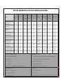
ISO hub specifications and wheel building information
Flange
>iÌiÀÊÀÛiÊ
Center to
-`iÊEÊ
>}iÊÀÛiÊ
ÀÛiÊ-`iÊ
Side (mm)
(mm)
Center to Flange
À>iÊÌÌ>V
iÌÊ Û>>LiÊ-«iÊ
ÀÛiÊ-`iÊ
Options
iÊÀ}
(mm)
33
1«}À>`iÊEÊ
Conversion
Options
Weight* (grams)
28, 32, 36
4
166
32, 36
4
164
£xÊ/
32, 36
5
197
ÓäÊ/
32, 36
5
207
Ó{Ê/
32, 36
5
240
33.9
+,É
28, 32, 36
1, 3
336
33.9
£äÉ£ÓÊ/
28, 32, 36
1, 3
320**
20.1
33.9
£ÓÊ/
28, 32, 36
1, 3
325
57.4
25.0
38.5
£äÉ£ÓÊ/
32, 36
3
336**
57.4
28.5
39.6
£äÉ£ÓÊ/
32, 36
3
338
157
57.4
28.5
39.6
£ÓÊ/
32, 36
3
344
135
57.4
32.3
31.0
+,É
28, 32, 36
411***
100
53.0
31.5
23.0
+,
32, 36
150
ÝiÊ/Þ«i
ÝiÊ7`Ì
Ê
(mm)
ISO front
two piece
100
57.4
31.3
22.2
+,
-"Ê£xÊ-ÊvÀÌ
one piece
100
57.4
31.3
22.2
£xÊ/
-"Ê£xÊÊvÀÌ
one piece
100
57.4
31.6
23.3
ISO 20mm front
one piece
110
57.4
31.6
23.3
ISO 24mm front
one piece
110
57.4
26.5
27.8
ISO 135 rear
one piece
135
57.4
20.1
-"Ê£ÎxÊÝÊ£äÉ£ÓÊÀi>À
one piece
135
57.4
20.1
-"Ê£{ÓÊÝÊ£ÓÊÀi>À
one piece
142
57.4
-"ʣʣxäÊÝÊ£äÉ£ÓÊÀi>À
one piece
150
-"ÊÓÊ£xäÊÝÊ£äÉ£ÓÊÀi>À
one piece
150
-"ÊÓÊ£xÇÊÝÊ£ÓÊÀi>À
one piece
ISO Single Speed rear
one piece
1ÛiÀÃ>ÊÃVÊvÀÌ
two piece
ÕLÊ/Þ«i
1ÛiÀÃ>ÊÃVÊÀi>À
one piece
135
53.0
21.0
34.0
+,É
32, 36
1, 3
282
1ÛiÀÃ>ÊÃVÊ-}iÊ-«ii`ÊÀi>À
one piece
135
53.0
32.0
34.2
+,É
32, 36
427***
1ÛiÀÃ>ÊÃVÊÀi>ÀÊÌ>`i
two piece
140
53.0
23.5
31.5
+,
32, 36
2, 3
284
1ÛiÀÃ>ÊÃVÊÀi>ÀÊÌ>`i
one piece
145
53.0
26.0
29.0
+,É
32, 36
3
366
1ÛiÀÃ>ÊÃVÊÀi>ÀÊÌ>`i
one piece
160
53.0
33.7
33.7
+,É
32, 36
3
388
£\ÊiiÀ>ÌÊ"iÊÊ-iÀ>ÊÊLi}ÃÊÜÌ
Ê££ä
1«}À>`iÊEÊ
ÛiÀÃÊ"«ÌÃ
Ó\ÊiiÀ>ÌÊ/ÜÊÊ-iÀ>ÊÊLi}ÃÊÜÌ
ÊÓ£ä
1:
ÛiÀÌLiÊÌÊ£ÎxÊ+,ÉÊ>Ýi]Ê£ÎxÊÝÊ£äÊ/]Ê£ÎxÊÝÊ£ÓÊ/]Ê£{ÓÊÝÊ£ÓÊ/]ÊÊ>`Ê£ÎxÊÌÜÊ«iViÊ+,Ê>Ýi
À>iÊÌÌ>V
iÌÊ"«ÌÃ
2:
ÛiÀÌLiÊÌÊ£Îä]Ê£Îx]Ê>`Ê£{äÊ>ÝiÊÜ`Ì
ÃÊÜ
iÊÕÃ}Ê>ÊÌÜÊ«iViÊ>Ýi
ÊÊ+,\ÊÊÊÊÊÊÊÊ+ÕVÊÀii>ÃiÊÞ
3:
Convertible to stainless steel driveshell
ÊÊ/\ÊÊÊÊÊÊÊÊÊ/
ÀÕ>ÝiÊÞÊ
4:
ÛiÀÌLiÊÌÊ+,Ê>`Ê£xÊÌ
ÀÕÊ>Ýi
5:
ÛiÀÌLiÊÌÊ£xÊ>`ÊÓäÊÌ
ÀÕÊ>Ýi]Ê>`ÊÓ{Ê>Ýi
ÊÊ+,É\ÊÊ+ÕVÊÀii>ÃiÊÀÊÕÌÃÊÕÌÃÊÞÊV«>ÌLiÊÜÌ
ÊÀi>ÀÊiÊ«iViÊ>Ýi®ÊÊÊ
7
iiÊÕ`}Ê-«iVwV>ÌÃ
Spoke Gauge:
13, 14, or 15 gauge
ÊÊ-«iÊ>V}Ê*>ÌÌiÀ\ÊÊÊÎÀÀiÊVÀÃÃ
ÊÊ-«iÊiÊ>iÌiÀ\ÊÊÊÓ°x
Small Parts Weights
ÊÊIÊÊÊÊ``Ê{n}ÊvÊ
ÕLÊvi>ÌÕÀiÃÊ>ÊÃÌ>iÃÃÊÃÌiiÊ`ÀÛiÃ
i
ÊÊIIÊÊÊ``Êx}ÊvÊÕÃ}Ê£äÊÌ
ÀÕÊ>Ýi
*** Weight includes 18t stainless steel cog (37g), single speed cog spacers (6g) singleiispeed cog lock ring {}®Ê>`ÊÕÌÃÊ{Ó}®
Classic abd BMX hub specifications and wheel building information
Hub Type
Axle Type
Axle Width
(mm)
Flange
Diameter
Drive Side
Flange
Diameter
Non-Drive
Side
Center to
Flange
Drive Side
(mm)
Center to
Frame
Flange nonAvailable Spoke
Attachment
Drive Side
Hole Drilling
Options
(mm)
Upgrade &
Conversion
Options
Weight* (grams)
Classic high flange front
two piece
100
53.0
53.0
34.3
Classic high flange 130 front
two piece
130
53.0
53.0
17.2
37.3
QR
28, 32, 36
1, 2, 3
276
Classic high flange 135 rear
one piece
135
53.0
53.0
21.0
33.5
QR/FB
28, 32, 36
1, 2, 3
302
Classic low flange front
two piece
100
40.0
40.0
34.0
34.0
QR
28, 32, 36
-
112
34.3
QR
28, 32, 36
-
136
Classic low flange 130 rear
two piece
130
53.0
44.0
18.5
38.5
QR
28, 32, 36
1, 2, 3
264
Classic low flange 135 rear
two piece
135
53.0
44.0
21.0
36.0
QR
28, 32, 36
1, 2, 3
266
Single Speed 130 rear
one piece
130
53.0
53.0
31.2
36.2
QR/FB
28, 32, 36
1
370a
34
Single Speed 135 rear
one piece
135
53.0
53.0
33.7
33.7
QR/FB
28, 32, 36
1
375a
BMX high flange front
one piece
100
53.0
53.0
34.3
34.3
BO
28, 32, 36
-
216b
BMX high flange rear
one piece
110
53.0
53.0
27.3
27.3
BO
28, 32, 36
-
388c
BMX low flange front
one piece
100
40.0
40.0
34.0
34.0
BO
28, 32, 36
-
194b
BMX low flange rear
one piece
110
53.0
44.0
27.0
30.0
BO
28, 32, 36
-
376c
Classic Tandem 140 rear
two piece
140
53.0
53.0
31.5
23.5
QR
28, 32, 36
1, 2, 3
282
Classic Tandem 145 rear
one piece
145
53.0
53.0
29.0
26.0
QR/FB
28, 32, 36
1, 2, 3
342d
Classic Tandem 160 rear
one piece
160
53.0
53.0
33.7
33.7
QR/FB
28, 32, 36
3
352d
G1: Generation One - Serial # begins with 1910
G2: Generation Two - Serial # begins with 2910
Upgrade & Conversion Options
1: Convertible to 135mm QR/FB axle, 135 x 10mm TA, 135 x 12mm TA, 142 x
12mm TA, and 135mm two piece QR axle
2: Convertible to 130mm, 135mm, and 140mm axle widths when using a two
piece axle
3: Convertible to stainless steel driveshell
4: Convertible to QR and 15mm thru axle
5: Convertible to 15mm and 20mm thru axle, and 24mm axle
Frame Attachment Options
QR:
Quick release only
TA:
Thru-axle only
QR/FB: Quick release or FunBolts (FunBolts only compatible with rear one piece axle)
Rev. 12/12-A
Wheel Building Specifications
Spoke Gauge:
13, 14, or 15 gauge
Spoke Lacing Pattern: 3-or-more cross
Spoke Hole Diameter: 2.5mm
Rev. 12/12-A
Small Parts Weights
* Add 48g if hub features a stainless steel driveshell
** Add 5g if using 10mm thru axle
*** Weight includes 18t stainless steel cog (37g), single speed cog spacers (6g) single
iiiiiiiii
iiiiiiiiiiispeed cog lock ring (4g) and FunBolts (42g)