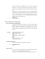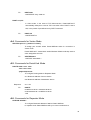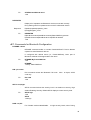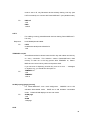
1
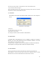
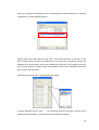
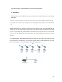
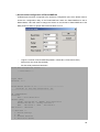
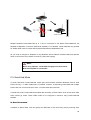
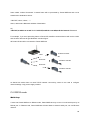
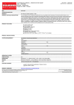
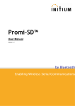
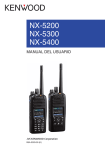
Parani-MSP100 For Wireless Multi-Serial Communications, based on Bluetooth Technology User Guide Version 1.0.2 2006-12-21 User Guide for the Parani-MSP100 Version 1.0.2 Firmware version 1.0.X Last revised on December 21, 2006 Printed in Korea Copyright Copyright 2006, Sena Technologies, Inc. All rights reserved. Sena Technologies reserves the right to make changes and improvements to its product without providing notice. Trademark Parani™ is a trademark of Sena Technologies, Inc. Windows® is a registered trademark of Microsoft Corporation. Ethernet® is a registered trademark of XEROX Corporation. Notice to Users Proper back-up systems and necessary safety devices should be utilized to protect against injury, death or property damage due to system failure. Such protection is the responsibility of the user. This device is not approved for use as a life-support or medical system. Any changes or modifications made to this device without the explicit approval or consent of Sena Technologies will void Sena Technologies of any liability or responsibility of injury or loss caused by any malfunction. Technical Support Sena Technologies, Inc. 210 Yangjae-dong, Seocho-gu Seoul 137-130, Korea Tel: (+82-2) 573-5422 Fax: (+82-2) 573-7710 E-Mail: [email protected] Website: http://www.sena.com 2 Contents 1. Introduction… … … … … … … … … … … … … … … … … … … … … … … … … … … … … … .5 1.1. Overview… … … .................................................................................................................... 5 1.2. Package Check List...............................................................................................................5 1.3. Product Specification............................................................................................................. 6 2. Getting Started… … … … … … … … … … … … … … … … … … … … … … … … … … … … … 8 2.1. External View........................................................................................................................9 2.2. LED Indicators.......................................................................................................................9 2.3. Connecting Parani-MSP100 to host .......................................................................................9 3. Installation… … … … … … … … … … … … … … … … … … … … … … … … … … … … … … .10 3.1. Network Settings ................................................................................................................. 10 3.2. LAN Access Profile.............................................................................................................. 14 3.3. Firmware Download ............................................................................................................ 14 3.3.1. Firmware Upgrade via TFTP...................................................................................... 14 3.3.2. Firmware Upgrade via Xmodem ................................................................................ 17 3.4. Serial Port… … … ................................................................................................................. 18 3.5. Reset/Reboot/Quit............................................................................................................... 19 4. Configuration… … … … … … … … … … … … … … … … … … … … … … … … … … … … … 20 4.1. Configuration via Parani-MSP100 Manager ......................................................................... 20 4.1.1. When Parani-MSP100 is connected to PC directly..................................................... 20 4.1.2. Log in Parani-MSP100 Manager................................................................................ 20 4.1.3. Operation Mode ........................................................................................................ 22 4.1.4. Bluetooth................................................................................................................... 30 4.1.5. Connection ................................................................................................................ 31 4.1.6. Neighborhoods .......................................................................................................... 32 4.1.7. Repeater ................................................................................................................... 33 4.2. Configuration via WEB ........................................................................................................ 34 4.2.1. Parani-MSP100 Configuration ................................................................................... 35 4.2.2. Operation Mode ........................................................................................................ 36 4.2.3. Network Setting ......................................................................................................... 37 4.2.4. Restore Factory Setting............................................................................................. 37 5. Approval Information… … … … … … … … … … … … … … … … … … … … … … … … … ..39 5.1. FCC… … .. ..................................................................… … … … … … … … … … … … … … … … ..39 5.1.1. FCC Compliance Statement ...................................................................................... 39 5.1.2. RF Exposure Statement ............................................................................................ 39 5.1.3. Do not ....................................................................................................................... 39 5.2. CE… … … .. .......................................................................................................................... 39 5.2.1. EC-R&TTE Directive.................................................................................................. 39 5.3. MIC… … … ........................................................................................................................... 39 5.4. Telec… … … ......................................................................................................................... 39 6. RF Information… … … … … … … … … … … … … … … … … … … … … … … … … … … … ..40 6.1. Radio Frequency Range...................................................................................................... 40 6.2. Number of Frequency Channel............................................................................................ 40 6.3. Transmission Method .......................................................................................................... 40 6.4. Modulation Method.............................................................................................................. 40 6.5. Radio Output Power ............................................................................................................ 40 6.6. Receiving Sensitivity ........................................................................................................... 40 6.7. Power Supply...................................................................................................................... 40 Appendix A: Control Command… … … … … … … … … … … … … … … … … … … … … .. 41 A.1. A.2. A.3. A.4. Basic Commands................................................................................................................ 42 Commands for Server Mode ............................................................................................... 43 Commands for Client Mode................................................................................................. 45 Commands for Vertex Mode................................................................................................ 46 3 A.5. A.6. A.7. A.8. Commands for Repeater Mode ........................................................................................... 46 Commands for Bluetooth Configuration ............................................................................... 47 Commands for Bluetooth Connection Management............................................................. 49 Other Commands................................................................................................................ 52 Appendix B: AT Commands… … … … … … … … … … … … … … … … … … … … … … … ..54 Appendix C: Operation Mode Information… … … … … … … … … … … … … … … … .. 58 C.1. Server Mode....................................................................................................................... 58 C.2. Client Mode ........................................................................................................................ 58 C.3. Vertex Mode ....................................................................................................................... 59 C.4. Repeater Mode................................................................................................................... 59 C.5. Serial Hub Mode................................................................................................................. 60 C.6. RS232 Mode ...................................................................................................................... 61 Appendix D: Using Parani-MSP100 with Serial/IP… … … … … … … … … … … … … . 64 D.1. Configuration when working with Serial/IP and Parani-MSP100 in Server Mode .................. 64 D.2. Configuration when working with Serial/IP and Parani-MSP100 in Client Mode ................... 67 Appendix E: Discovery Protocol… … … … … … … … … … … … … … … … … … … … … . 71 Appendix F: Warranty … … … … … … … ..… … … … … … … … … … … … … … … … … … . 73 F.1. GENERAL WARRANTY POLICY......................................................................................... 73 F.2. LIMITATION OF LIABILITY .................................................................................................. 73 F.3. HARDWARE PRODUCT WARRANTY DETAILS ................................................................. 73 F.4. SOFTWARE PRODUCT WARRANTY DETAILS .................................................................. 73 F.5. THIRD-PARTY SOFTWARE PRODUCT WARRANTY DETAILS .......................................... 73 4 1. Introduction 1.1. Overview The Parani-MSP100 enables multiple Bluetooth devices to connect to the Ethernet network simultaneously and without delay when they are within range. The Parani-MSP100 provides Class 1 Bluetooth wireless connectivity to Ethernet/Fast Ethernet. It supports all Bluetooth devices compatible with Bluetooth Profiles for the Serial Port, Dial-up Networking, LAN Access and PAN. Along with the Serial Port Profile support, the Parani-MSP100 is the ideal solution for the replacement of the wired serial port application. The Parani-MSP100 supports versatile host modes for various user applications, i.e. TCP Server and Client modes for TCP/IP-Bluetooth replay applications, Vertex mode for multicasting, Repeater mode, Serial Hub mode and RS232 mode. The Parani-MSP100 runs on embedded Linux operating system, with Flash memory for easy software upgrades, and built-in Web server and Web interface for quick installation, and remote configuration and management. The Parani-MSP100 uses the RADIUS protocol for user authentication. Typical application areas of the Parani-MSP100 include: • Truck/Bus monitoring system • Car Diagnostics • Wireless POS system • Wireless Factory monitoringPLC programming • Wireless machine (healthcare/industrial) monitoring • Wireless Printing • Wireless logistics Parani-SD Parani-MSP100 Fig. 1.1.1 Application Diagram 1.2. Package Check List - DC Power Adapter Quick Start Guide Serial Data Cable Ethernet Cross Cable Dipole antenna CD-ROM, including the Parani-MSP100 Manager Software, COM Port Redirector, Tips_Serial/IP Com Port Redirector and manual 5 1.3. Product Specification Ethernet Interface Parani-MSP100 10/100 Base-T Ethernet with RJ45 connector Supports Static IP and Dynamic IP address Bluetooth Interface Bluetooth v2.0 * Class 1 Level: 18dBm Frequency: 2.4GHz Profiles - Serial Port, LAN Access, PAN, Dial up Networking Working distance: Dipole–Default Antenna 150m Dipole–Dipole Antenna 200m Dipole–Patch Antenna 400m Patch–Patch Antenna 1000m Point to multi point MSP100 : Max. 7 Bluetooth links connectivity MSP100 + USB Dongle : Max. 14 Bluetooth links Network Protocols HTTP, TFTP, Telnet, DHCP Server/Client SNMP v1/v2/v3 PPP server and PPP tunneling RADIUS Configuration Parani-MSP100 Manager Web, Telnet, Serial Console Modem AT command set Diagnostic LED Power, Status, Error, EXT and INT Power Supply voltage: 5V DC Supply current - Minimum 2A Common Power supply options: Power via a standard AC-plug DC-adapter LAN 10/100 x2, Hardware Interface Inclusive Hub function. Ethernet/RS232C com. supported Built-in Bluetooth1 USB A-type port for USB extension dongle Environmental Operating temperature: 0 ~ 50 oC Storage temperature: -20 ~ 70 oC Humidity: 90% Non-condensing Physical properties Dimension (LxWxH) 147 x 112 x 32 (mm) 5.8 x 4.4 x 1.3 ( in.) Weight: 225g Approvals FCC, CE, MIC, Telec COM port redirector Serial/IP Software Warranty 3-year limited warranty 6 * Note : Bluetooth v2.0 supports improved AFH function. AFH function is to mitigate the interference between WiFi and Bluetooth radios by automatically avoiding the active WiFi channel from Bluetooth link. However, AFH does not provide a complete solution making WiFi and Bluetooth work together in harmony. It is highly recommended for users to test their wireless system enough before deployment since the overall system performance is affected by various environmental factors such as distance between them. 7 2. Getting Started 2.1. External View <Fig. 1.3.1> Parani-MSP100 external view (1) DIP Switch Users may select several different methods of data communication with the Host. Default setting is TCP/IP communication using no.4 RJ45 marked EXT, but if users need, data communication by no.3 RS232 Interface marked “IOIOI” is also possible. • If DIP switch is on the side of drawing , Parani-MSP100 communicates with Host via Ethernet line (TCP/IP), while the RS232 port will be used for configuration purposes only (In this case, DIP switch must be positioned on the side of drawing . Refer to Section 3.1 for more details on configuration). • If users want to use RS232 communication mode (data only), please change the direction of switch to the opposite direction. NOTE: If the DIP switch is switched to a new position the Parani -MSP100 will need to be powercycled to take effect. (2) Power Port: For Power Adapter connection (3) RS232 Interface marked “IOIOI”: For Parani-MSP100 network configuration via RS232 serial cable - One RS232 serial cable, both ends female DB-9 interfaces, are provided with the Parani-MSP100. This port can be used for both Configuration of Parani-MSP100 and Data communication with Host. (4) RJ45 marked EXT.: For connection to Host or HUB devices. For connection to PC, use a 8 Crossed cable; for connection to HUB, use Straight Ethernet cable. (5) RJ45 marked INT.: Hub port for connection to another Parani-MSP100. With this, ParaniMSP100s can be chained without network hub. This is for the better user experience of convenient installation. Use a straight cable for this purpose. 2.2. LED Indicators - POWER: POWER ON/OFF Status - STATUS: Parani-MSP100 Status - ERROR: Error Event Status - LINE/ACT1, LINE/ACT2: RJ45 connections Status STATUS LED ON Blinking ERROR LED OFF OFF OFF ON ON Blinking Flashing Flashing Description Normal Connecting to Station Parani-MSP100 (In Repeater Mode) Internal Bluetooth module operation malfunction LAN connection Error (Connecting to ADSL or waiting for DHCP server response) Upgrading Firmware DO NOT turn off Parani-MSP100 during firmware upgrade; turning off Parani -MSP100 during firmware update may cause malfunction. 2.3. Connecting Parani-MSP100 to host Step 1: Connect the power jack to the power connector of the Parani-MSP100 using DC power adapter included in the package. If power is properly supplied, the LEDs for ‘Power’and ‘Status’will maintain a solid green color. Step 2: Connect the one end of the Ethernet cable to the ‘EXT’port of the Parani-MSP100 and the other to the Ethernet network. If the cable is properly hooked up, the Parani-MSP100 will have a valid connection to the Ethernet network by indicating ‘EXT’LED becomes green and is blinking if there’s any corresponding packet traffic. Step 3: Only for 1st time installation, attach the serial console cable to the Parani-MSP100. You are ready to install the Parani-MSP100 using serial console. 9 3. Installation Parani -MSP100 Installation Configuration via serial cable TCP/IP mode Network Configuration Mode configuration RS232 Mode Serial Port Configuration Change of DIPswitch Connection from Bluetooth Terminal device (Parani-SD) 3.1. Network Settings (1) Parani-MSP100 power-up; ‘POWER’and ‘STATUS’LEDs display green (2) Parani-MSP100 network configuration: connect Parani-MSP100 to PC via RS232 cable(Position of DIP switch is on the side of drawing .) (3) Open HyperTerminal (4) Set PC COM port; Baud rate 115200 / 8 Data bit / non-parity / 1 stop bit / no hardware flow control (5) Press Enter key; the following information as is displayed on a HyperTerminal screen; If Parani-MSP100 prompts Login ID / password, default values are: Login: admin Password: admin 10 (6) Default Parani-MSP100 IP address factory setting is 192.168.1.10. Please revise settings to reflect the user’s appropriate networking environment IP address. (7) To revise Network Settings, Enter “1” as displayed below. (8) Network Settings sub menu will be displayed. (9) If No.1, Static IP, is selected, the following is displayed on screen: (10) Enter user Static IP address. In the example below, 192.168.0.3 is entered for the Parani-MSP100 IP address. Enter the user appropriate network IP address. 11 (11) Please enter your Netmask/Gateway/DNS information, as shown below: (12) Press Enter: Parani-MSP100 will prompt reboot request. Enter ‘Y’[Yes]; press Enter to reboot Parani-MSP100 to apply the revised Network Settings. (13) Enter Login ID and Password. Default ID: admin, Password: admin (14) Revised Network settings are displayed 12 <An example: Revised Network Settings> (15) Networking configuration is complete. The preceding example shows static IP assignment to Parani-MSP100. The user should select static, DHCP or PPPoE IP as needed. 3.2. LAN Access Profile Parani-MSP100 supports LAN Access Profile for Bluetooth networking Access Point. connection of Parani-MSP100 to ADSL, the internet is accessible via Bluetooth. By direct Select menu 2. LAP by entering ‘2’; Parani-MSP100 prompts for LAP profile enable/disable. ‘Y’[Yes] to enable or ‘N’[No] to disable LAP profile. Select 3.3. Firmware Download Parani-MSP100 enables users to upgrade the firmware. The SENA customer support team offers available firmware upgrades via Xmodem or TFTP user download; menu no. 3. Firmware Download. During Firmware download, STATUS and ERROR LEDs flash. DO NOT TURN OFF ParaniMSP100 during firmware download. Turning off Parani-MSP100 during firmware download may result in operation malfunction. There are two methods of firmware upgrade: 1. Xmodem 2. TFTP. 3.3.1 Firmware Upgrade via TFTP • Users may upgrade the firmware using TFTP via Crossed cable. 3. Firmware Download → 2.TFTP 13 • Then you will get following screen: TFTPd ready. Send firmware using TFTP. Windows 2000/XP: tftp –i 192.168.220.4 put <filename> * Here, a sample IP address, 192.168.220.4 has been assigned to Parani-MSP100. User must use your own IP address. User must put your own IP address. • Please keep this serial console connected. • After you save the Parani-MSP100 upgrade ROM file to your PC, please open COMMAND window as in below. • Users need to make sure that the upgrade ROM file is in the same location or users need to specify the exact location to send the ROM file to the connected Parani -MSP100 via Crossed Ethernet cable. • Below window is showing the procedure of sending ROM file named “parani.rom” to the connected Parani-MSP100 via TFTP. • Users will be able to check the status of firmware upgrade in Serial console. 14 • During upgrade, LEDs will flashing and users should NOT turn off Parani-MSP100 this time. If user cannot send the ROM file, please check the network connection status. • Once ROM file is delivered to the connected Parani-MSP100, the upgrade firmware will be recorded to memory. During this time both STATUS LED and ERROR LED will flashing speedily. NEVER turn off Parani-MSP100 during this firmware recording. • Once finished, please resupply power to Parani-MSP100 for applying. 15 3.3.2 Firmware Upgrade via Xmodem Users may upgrade the firmware using Xmodem protocol via RS232 serial cable. <Upgrade firmware via Xmodem> 3.4 Serial Port Serial port of Parani-MSP100 can be used for both Configuration and Data communication. For configuration, users need to change the DIPswitch of Parani-MSP100 to the right. Users may set configuration of serial port communication in this menu. Below figure is showing that ‘115200 bps 8-N-1 hardware’which means ‘115200 bps, 8 data bit, None parity, 1 stop bit, hardware flow control (RTS/CTS). 16 Configurable ranges: Baud rate 1200 ~ 115200 bps Character size 8, 7, 6, 5 bits Parity Check None / Even / Odd Stop Bit 1 bit or 2 bits Flow Control Hardware (RTS/CTS), Software (XOn/Off), None For applying changed configuration, please RESUPPLY the power, and then Parani-MSP100 will start to operate as RS232 mode. Advice: If you need to do data communication via RS232 port, you do not need to configure Network settings. 3.5 Reset/Reboot/Quit Entering no. 5, Parani-MSP100 RESET, in the main menu, restores all factory Default value settings. REBOOT restarts Parani-MSP100 for new configuration application. QUIT instantly aborts current processing. 17 4. Configuration Once users are finished configuring network settings using serial console. Users need to select the operation mode of Parani-MSP100. Following three (3) ways can be used for selection of operation mode: 1. Via Parani-MSP100 configuration software 2. Via Telnet (Control port) 3. Via Web browser (Internet Explorer, etc.) In this chapter, a guide on usage of the Parani-MSP100 configuration software will be introduced. How to configure via Telnet or Web browser will be introduced in the Appendix. 4.1. Configuration via Parani-MSP100 Manager 4.1.1. When Parani-MSP100 is connected to PC directly If users are going to connect Host PC and Parani-MSP100 directly using a crossed cable, network settings as in the chapter 3.1 will not be required. Parani-MSP100 has factory settings: Static IP 192.168.1.10 For communication with Parani-MSP100, set the IP of Host PC to have proper address. If you connected Parani-MSP100 to the Network, not to the Host PC, skip this chapter and go to next chapter 4.1.2. Open your Network Connections and see Property information of Local Network. Change your IP address to Static: IP: 192.168.1.11 Subnet: 255.255.255.0 Gateway: 192.168.1.1 These settings for direct communication only with Parani-MSP100 connected. 4.1.2. Log in Parani-MSP100 Manager For easier configuration and monitoring on a specific Parani-MSP100, which has been installed locally or remotely, users may use Parani-MSP100 software. Start Parani-MSP100 software, and press “Search” button on the left side. 18 Please select one Parani-MSP100 you would like to access and press “Connect” button.” You will need to enter UserID/Password: admin/admin 19 4.1.3. Operation Mode Parani-MSP100 may be set to different type of modes, so users may have to select one for its own application. There are 6 types of modes: Server, Client, Vertex, Repeater, Serial Hub, and RS232. • Operation Mode This shows current type of Mode. • Mode Change Users may change and select the type of Operation. • Search Users may search Parani-MSP100 on the network. Note: While Bluetooth devices are connected to Parani-MSP100, mode change is not possible. A) Server Mode In Sever Mode, Parani-MSP100 will operate as a Server on the network. Host PC will connect to Parani-MSP100 via TCP/IP Ethernet and Parani-MSP100 will recieve the connection. After connection, full duplexing is possible. Users need to select the Port number to standby to receive connection from Host PC. 20 <Configuration of Server Mode> • Default Data Port If unregistered device tries to connect to Parani-MSP100, Parani -MSP100 will assign the port number consecutively from Default Data port. • KeepAlive Timeout When TCP connection is stopped unexpectedly (Ex. Power off of Host PC), Parani-MSP100 will request NULL during KeepAlive Timeout (second). If there is no response during this Timeout, TCP connection will be finished. • Do not disconnect TCP socket In Server Mode, each TCP connection and Bluetooth connection will be matched as point-topoint. When new Bluetooth connection is established, new TCP connection will be established as well. So, if Bluetooth connection is stopped, TCP connection can be finished. To prevent this, users may use this option, so does not need to make TCP connection whenever Bluetooth connection is stopped. • Register Bluetooth Device: Shows the Bluetooth devices registered. • Add: Add Bluetooth device to register. • Delete: Remove Bluetooth device registered. • Modify: Modify Port of the selected device. B) Client Mode In Client Mode, Parani-MSP100 will act as a TCP client. When a Bluetooth device connects to Parani-MSP100, Parani-MSP100 will try to connect to the designated Host PC. So, Host PC 21 should be in standby status. In Client Mode, please select the IP address and port number of the Host PC to connect. <Configuration of IP address of Host> Select “Advanced Configuration”button. Here, users may configure which Bluetooth device will connect to which Host, as they need. Bluetooth device “00:0B:53:16:12:C7” will connect to Host “192.168.20.251”, port no. 5002. Bluetooth device “00:0B:53:16:12:74” will connect to Host “192.168.20.252”, port no. 5004. Bluetooth devices, which are not configured to connect to a specific Host, will connect to Default Host in Host information. <Configuration of Client Mode> • Host IP Address For network Host Server IP address entry • Host Port Number For Server Host port no. entry • Re-connect automatically if link is lost. 22 For Host connect retry, if failed. Retry frequency is set in the preceding function. • Try to Connect to Server every [] ms When Parani-MSP100 fails to open a data channel connecting to Host, enter the connection retry frequency. Entering 0 [zero] obtains retry abort. C) Vertex Mode Parani-MSP100 Vertex Mode avails Wireless RS485 multidrop service when assigned at this site. <Configuration of Vertex Mode> • Vertex Port For Parani-MSP100 Vertex port no. entry. • Max Number of Connections For entering the number of Hosts connectable to Parani-MSP100. D) Repeater Mode In Repeater Mode, Parani-MSP100 will act as a Repeater to expand the coverage of Bluetooth. Let’s call the Parani-MSP100 that will act as Repeater, “Repeater”, and call the Parani-MSP100 of normal operation as “Station”. In Repeater Mode, configuration required is only the Address of the Station Parani-MSP100. When Repeater is connecting the Station, Status LED of Repeater is blinking. E) Serial Hub Mode Users may transmit/receive data via Parani-MSP100 in Serial Hub mode (Serial Hub). Parani-MSP100 in serial hub mode relay the data from a Bluetooth device to another Bluetooth device connected to Parani-MSP100. No network host is involved. 23 Users may configure Parani-MSP100 how to handle data from Bluetooth devices in advanced configuration of Parani-MSP100 software. Routing table shows paths that data will follow. Arrow shows direction of data flow. In the above example, data coming from 00:0B:53:16:21:4C will be sent to 00:0B:53:12:09:F3 and 00:0B:53:16:11:CB and data coming from 00:0B:53:16:11:CB will be sent 00:0B:53:16:21:4C in the reverse direction, but data coming from 00:0B:53:12:09:F3 will be dismissed because it has no path in the route table. Press Add to add route entry. Following dialog will appear. To select Bluetooth device, press ‘… ’, then Bluetooth devices connected currently will be displayed in another dialog or enter bluetooth device address manually. 24 If you mark checkbox, opposite direction route will be also registered. F) RS232 Mode In RS232 Mode, Parani-MSP100 may communicate with other Bluetooth devices via a RS232 serial cable. User s can communicate point to multi point communication via Parani-MSP100 with Parani-SD. In this case, the master is the serial port of the Parani-MSP100 and slaves are the Parani-SD units. RS232 Mode works very similar to a 485 multi-drop connection, where the Parani-MSP100 is a master unit and each Parani-SD will act as the slaves. When data is transmitted to the serial port of the Parani-MSP100, Parani-MSP100 transmits the same data to each of the Parani-SD units. If one of the Parani-SD units transmit data, only Parani-MSP100 serial port will receive that data. In the RS232 Mode, Parani-MSP100 transmits the serial port data to all of the Parani-SD units at the same time. Consequently, if some slaves transmit data to Parani-MSP100 at the same time then serial data to the Parani-MSP100 will be blended together. 25 i) Set the serial configuration of Parani-MSP100 As RS232 port has been configured to be used as a Configuration port, which allows users to access the configuration utility of the Parani-MSP100. When the Parani-MSP100 is set to RS232 Mode, users will need to change the Switch on the left side of Parani-MSP100 to the Data position to allow for proper data communication to occur. - Login the console of Parani-MSP100 (Default: 115200-N-8-1-Flowcontrol None) - Select menu #4. Serial Port (RS232) - Set the serial parameters like below. Parani-MSP Configuration Console ----- Press Enter --- login: admin Password: ***** Parani-MSP100 Version v1.0.0 ----------------------------Copyright (C) 2006 Sena Technologies, Inc. ----------------------------------------------SN : MSP060900003 Bluetooth dev0 - 00:01:95:20:04:51 Network [dhcp] IPaddr 192.168.222.16 HWaddr 00:01:95:00:00:32 Netmask 255.255.0.0 Gateway 192.168.1.1 DNS1 168.126.63.1 DNS2 168.126.63.2 LAP profile : [disabled] --- Main Menu --1. Network Settings 2. LAP 3. Firmware Download 4. Serial Port (RS232) 26 5. 6. 7. 8. Reset Reboot Change password System Log q. Quit >> 4 --- Serial Port Configuration --AT command interface: Disabled 115200 bps 8-N-1 hardware 1. 2. 3. 4. 5. 6. Baudrate Character Size Parity Stopbit Flow Control AT command q. Quit >> - Logout the console (q.Quit) - To apply changes to the configuration, turn off the Parani-MSP100. - Users will need to move the Switch on the left side of Parani-MSP100 to right side position for Data communication. - Turn on the Parani-MSP100, and then Parani-MSP100 will start operating in RS232 mode. Please note that if you need to make use of data communication via RS232 port, you will not need to configure Network settings. ii) Set the Parani-SD configuration - Make connection from Parani-SD to the Parani -MSP100. 27 - Press [Disconnect] button in the connection window of Parani-SD Manager. - See the Device Setting window in the Parani-SD Manager and set operation mode as MODE1 like below. - For configuration of mulitple Parani-SD’s please use the connection techniques as described above. 4.1.4. Bluetooth In this page, users can find current status of Parani-MSP100. 28 You can see the process of command at the bottom of each page as in red circle above. TIP: For 14 connections in Parani-MSP100+USB Dongle, please change the MaxDT to 12 above, after installing USB extension dongle provided. TIP: It may take more then 5 minutes to be connected with MSP if SD are close by 1-ton relationship. 4.1.5. Connection In this page, users may MONITOR the connection status of devices to Parani-MSP100. Now, three Bluetooth devices have been connected for Wireless serial communications as below. 29 Left square shows quality of connection. Green square is good, red square is poor quality. If you want to disconnect a Bluetooth terminal, you can do the job using DICONNECT button on the left. 4.1.6. Neighborhoods This page is used to search nearby Bluetooth devices, configuration of search Interval, and the Length. < Neighborhoods> Bluetooth Friendly Name of devices that were connected previously will appear in the Bluetooth Friendly name box. 30 4.1.7. Repeater This page shows tree-structure how Repeater Parani-MSP100 and terminal devices are connected to the Station Parani-MSP100. If user’s Parani-MSP100 is in Repeater Mode, nothing will be showed. In the captured window below, Repeater Parani-MSP100 is connected to a Station Parani-MSP100 and a Parani-SD is connected Repeater (00:0B:53:20:04:51). 4.1.8. Parani-MSP100 information Users may see Parani-MSP100 information currently accessing. 31 Pressing ‘Log’button, system log messages will appear in notepad. System log is the source of invaluable information when the problems occur during operation. 4.2. Configuration via WEB Parani-MSP100 configuration access is available via Telnet or a local Web browser. SENA provides Web user interface to expedite Parani-MSP100 configure/manage and current status check functions. To access Parani-MSP100 via Web interface, open a web browser and enter the Parani-MSP100 IP address in the address area. Here is shown the 192.168.222.7 address assigned to Parani-MSP100 in the preceding configuration example. Enter the default ID: admin, Password: admin. 32 4.2.1. Parani-MSP100 Configuration • Basic Setting (1) Bluetooth name: For user Parani-MSP100 name revision (2) Maximum Connection: For configuring the maximum number of Bluetooth devices connectable to Parani-MSP100. Default maximum is 7. (3) Discoverable: When checked, Parani-MSP100 is in INQUIRY mode, discovering in-range Bluetooth devices. (4) Connectable: When checked, Parani-MSP100 is in PAGE mode, connecting to Bluetooth devices. (5) Pairable: For Pairing mode enable/disable. When in need of high security, set Pairable option to UNCHECKED, enabling High Security. When this option is NOT checked, other Bluetooth devices, except those previously connected to Parani-MSP100, cannot connect to Parani-MSP100, even via PIN code. (6) Control port: For control port number entry. Default value is 2525. • Buffering (1) Buffering: For Buffering function enable/disable * Firstly set Header and Trailer, secondly turn on Buffering option. (2) Header: For buffer frame header entry. Enter alphabet or HexaCode. (3) Trailer: For buffer frame trailer entry. Enter alphabet or HexaCode. • Security 33 (1) Pin code: For Bluetooth Pin code entry (2) Security: For security level entry 4.2.2. Operation Mode Parani-MSP100 accesses 3 types of operation modes. Select according to user requirement and application. • Server Mode (1) Base port: For Parani-MSP100 Server mode default port configuration (2) List: For assessment of currently connected Bluetooth devices (3) Bdaddr/btname: Enter address or preferred name of Bluetooth device/s to BIND. (4) Port no: Enter a specific port no. to assign to the Bluetooth device selected in no. 3. (5) vBIND buttons: Add/Delete/Clear To delete more than one device from the bound list, press Shift or Ctrl key while using the leftclick button on your computer mouse. • Client Mode In Client Mode, Parani-MSP100 operates as client; Host PC becomes a server. (1) IP: For network Host Server IP address entry (2) Port: For Server Host port no. entry (3) [] Try to connect to server every [] ms: When Parani-MSP100 fails to open a data channel connecting to Host, enter the connection retry frequency. Entering 0 [zero] obtains retry abort. 34 (4) [] Re-connect automatically if link is lost. For Host connect retry, if failed. Retry frequency is set in the preceding function. • Vertex Mode Parani-MSP100 Vertex Mode avails Wireless RS485 multidrop service when assigned at this site. (1) Vertex port: For Parani-MSP100 Vertex port no. entry. (2) Allow [] TCP connections to vertex port: For entering the number of Hosts connectable to Parani-MSP100. 4.2.3. Network Setting For user Parani-MSP100 network setting. (1) [] use DHCP: When checked, Parani-MSP100 receives IP address from DHCP server. (2) IP address/Network mask/Gateway/DNS: Enter appropriate data to assign static IP address for Parani-MSP100. (3) MAC: Displays MAC Parani-MSP100 address; non-user entry (4) [] use ADSL: Select this option when ADSL networking (5) User/Pass: Enter ID/password data for ADSL login. 4.2.4. Restore Factory Setting To reset to Parani-MSP100 default factory settings, click the ’Restore’button. 35 36 5. Approval Information 5.1. FCC 5.1.1. FCC Compliance Statement This device complies with part 15 of the FCC Rules. Operation is subject to the following two conditions: (1) This device may not cause harmful interference, and (2) This device must accept any interference received, Including interference that may cause undesired operation 5.1.2. RF Exposure Statement The equipment complies with FCC RF radiation exposure limits set forth for an uncontrolled environment. This device and its antenna must not be co-located or operation in conjunction with any other antenna or transmitter. 5.1.3. Do not Any changes or modifications to the equipment not expressly approved by the party responsible for compliance could void user’s authority to operate the equipment. 5.2. CE 5.2.1. EC-R&TTE Directive Directive 1999/5/EC. 5.3. MIC 5.4. Telec Construction Design Certification No. 006NYC0070 37 6. RF Information 6.1. Radio Frequency Range 2.402~2.480GHz 6.2. Number of Frequency Channel 79 channels 6.3. Transmission Method FHSS(Frequency Hopping Spread Spectrum) 6.4. Modulation Method GFSK(Gaussian-filtered Frequency Shift Keying) 6.5. Radio Output Power +18dBm 6.6. Receiving Sensitivity -88dBm 6.7. Power Supply DC5V 38 Appendix A: Control Commands Parani-MSP100 is configurable and controllable by Control commands through control TCP port. Prom-MSP software is the GUI version of Control commands for easy use by customers. As all of the control commands, in Parani-MSP100 software, are listed in the bottom window, it gives users insight how each commands work. Using control TCP port, users can make their own application control Parani-MSP100 by themselves. This means users do not need to equip expensive Bluetooth development kit but may develop Bluetooth solution to meet each needs by simple commands. Parani-MSP100™ is cost-effective and time-saving solution for users. By using telnet program, users may use Control commands easily. Rich-featured telnet software like “PuTTY”can be also useful. PuTTY Download: http://www.chiark.greenend.org.uk/~sgtatham/putty/download.html 39 Fig. 2.1.1 PuTTY Press ‘Open’, then following telnet session will be opened. Enter ‘user admin’and ‘pass admin’to access Parani-MSP100 via Control Commands. Every command responds with +OK if successful, otherwise –ERR. A.1. Basic Commands 40 USER <username> : Ex.: To enter Log in Name USER admin +OK Password required PASS <password> [new password] : To enter or change the Password for logging in. Below Example shows how to change Password from ‘admin’to ‘1234’ Ex: PASS admin +OK User Authenticated PASS admin 1234 +OK QUIT : Ex.: To quit the communication with Parani-MSP100 QUIT +OK Disconnected MODE [server|client|vertex|hub|repeater|rs232] : To check or change the current Operation MODE of Parani-MSP100. If any of Bluetooth devices are connected to Parani-MSP100, MODE change is not allowed. Before changing the MODE, please drop all of Bluetooth connections first. Ex.: MODE +OK Server Mode MODE CLIENT +OK Client Mode A.2. Commands for Server Mode PORT [port no.] : To configure default data port number of Server Mode Parani-MSP100. If a Bluetooth device, which is not pre-registered to Parani-MSP100, has connected to Parani-MSP100, port number will be assigned automatically by Parani-MSP100. Users may check the port numbers used by LIST command. 41 Ex.: PORT +OK PORT 5000 PORT 6000 +OK PORT 6000 BIND <bdaddr|name> <port> : A static port number may be assigned to a designated Bluetooth device using BIND command. A Bluetooth device can be specified by either friendly name or Bluetooth address. Response: Ex.: +OK index|name|bdaddr|port BIND 00:0B:53:00:00:01 8000 +OK BIND Parani-SD 8001 +OK BIND 0||00:0B:53:00:00:01|8000 1|Parani-SD||8000 +OK RELE <port no.> : If users do not need to use a bound port number, RELE command can be used to release the port number. Ex.: RELE 8000 +OK PRSV <on|off> : A TCP data port is opened as a Bluetooth connection is made. So, when Bluetooth connection is closed, the corresponding TCP port is also closed. If this behavior interferes with your usage scenario, this option will help. When this option is enabled, TCP connection remains regardless of Bluetooth connection. Users do not need to make TCP connection each time whenever Bluetooth connection is closed for a while. Ex.: PRSV on +OK KATO <time> <probe> <interval> : To configure ‘TCP Keep Alive Time’ When Host, which is communicating with Parani-MSP100 via network, is 42 stalled unintentionally, Parani-MSP100 cannot aware this unexpected disconnection. Accordingly, Parani-MSP100 sends beacon packets to monitor connection status when there is no data communication for certain time. When there is no data communication for <time>, Parani-MSP100 will send beacon packet <probe> times to monitor the connection, by each <interval>, before closing the connection. Below example means when there is no communication for 10 min., Parani-MSP100 will send beacon packets 3 times by 10 seconds interval. Ex.: KATO 600 3 10 +OK KATO 600 3 10 A.3. Commands for Client Mode SERV <IP Address:Port> [bdaddr|name] : To assign IP address and port number of server host where ParaniMSP100 will send connection request in client mode. If you enter either bluetooth address or friendly name of the Bluetooth device, you may configure different host addresses and port numbers for each Bluetooth devices. Response: Ex.: index|name|bdaddr|server_IP:port SERV 192.168.1.11:9000 +OK SERV 192.168.1.11:9001 Parani-SD +OK SERV 0|Parani-SD||192.168.1.11:9001 +OK 192.168.1.11:9000 DELSERV <bdaddr|name> : Ex.: To delete Host information stored by SERV command. DELSERV Parani-SD +OK REPT <interval> : When connection to Host is failed, users may configure Retrial period of connection. Unit: millisecond, Default value: 5000 ms If the value is ‘0’, Parani-MSP100 will try to recover connection only once. 43 Ex.: REPT 3000 +OK REPEAT every 3000 ms PSIST <on|off> : In Client mode, in the event of TCP disconnection, Parani-MSP100™ automatically attempts to recover TCP connection when PSIST is set to ON, in the period of pre-defined ms by REPT command. Ex.: PSIST ON +OK PERSIST on A.4. Commands for Vertex Mode VERTEX <port no.> [number of clients] : To assign port number where Parani-MSP100 waits for connection in Vertex mode. Parani-MSP100™ Vertex Mode avails Wireless RS485 multi-drop service when assigned at this site. Ex.: VERTEX 4000 1 +OK PORT 4000 MAX 1 A.5. Commands for Serial Hub Mode ROUTE <add> <src> <dst> <del> <src> <dst> <ptp|multi|manual> : To configure Routing table for Repeater Mode. src: Bluetooth address of source device dst: Bluetooth address of destination device Response: Ex.: src > dst ROUTE 00:0B:53:12:03:A8 > 00:00:00:00:00:00 00:00:00:00:00:00 > 00:0B:53:12:03:A8 +OK A.6. Commands for Repeater Mode STATION <bdaddr> : To configure Bluetooth address of station Parani-MSP100. In repeater mode Parani-MSP100 will try to connect to this device. 44 Ex.: STATION 00:0B:53:00:00:01 +OK REPEATER : Display all of repeaters and Bluetooth devices connected currently. Entry starting with R is repeater and one with P is Bluetooth device. Response: R|station|repeater|repeater_name P|msp|peer|peer_name Ex.: REPEATER R|00:0B:53:00:00:01|00:0B:53:00:00:02|Parani-MSP100_001002 P|00:0B:53:00:00:02|00:0B:53:00:00:10|PSDv3b-000010 +OK A.7. Commands for Bluetooth Configuration BTNAME <name> : BTNAME command audits or revises Parani-MSP100™ Device Names exposed to other Bluetooth devices. If configured with default name (i.e., Parani-MSP100), lower part of Bluetooth address will be appended to the name. Ex.: BTNAME My Parani-MSP100 +OK BTNAME +OK My Parani-MSP100 PIN <pin-code> : PIN command revises the Bluetooth PIN code. Max.: 16 bytes, ASCII code only. Ex.: PIN 1234 +OK SECU <low|high> : SECU command revises the security level. Low obtains no security; High obtains Enabling Security. Default SECU displays current security level. Ex.: SECU high +OK SECU +OK high PAIR <on|off> : For Pairable mode enable/disable. In High security levels, when Paring 45 mode is set to off, only Bluetooth devices already sharing Link Key (see LKEY command) can connect with Parani-MSP100™ (non-pairable mode) Ex.: PAIR off +OK PAIR +OK off LKEY : For auditing currently paired Bluetooth devices sharing Parani-MSP100™ . Link Key. Response: Ex.: local bdaddr|remote bdaddr LKEY 00:0B:53:20:00:63|00:08:1B:00:52:72 +OK TEMPKEY <on|off> : Some Bluetooth device doesn’t save their link key and makes new link key on every connection. This behavior causes Parani-MSP100’s flash memory to wear out in the long period. With TEMPKEY on, ParaniMSP100 won’t save link key neither and protects itself. If you see tons of ‘Replacing hci0 link key xx:xx:xx:xx:xx:xx … ’messages on System Log, you should turn this option on. Ex.: TEMPKEY on +OK TEMPKEY +OK on SCAN [inquiry] [page] [noscan] : For Parani-MSP100™ scan mode assignment. activates discoverable mode. INQUIRY set to ON PAGE set to ON activates connectable mode. Default SCAN displays current scan mode. Ex.: SCAN page +OK SCAN +OK page STAT 46 : Displays current Bluetooth device status If any background task running, it will show [PENDING]. Response: Ex.: idx|bdaddr|tx_byte|rx_byte|err_tx|err_rx STAT 0|00:0B:53:20:00:63|1710|3513|0|0 +OK AFH [channel] … : This command will activate 802.11b Wi-Fi Combo mode, in which ParaniMSP100 doesn’t make use of the ranges of frequencies where co-existing 802.11b Wi -Fi devices work. Specify channel 0(zero) to disable combo mode. When enabled, overall throughput will be reduced. Ex.: AFH 10 11 +OK AFH +OK AFH 10 11 AFH 0 +OK A.8. Commands for Bluetooth Connection Management LIST : To see connected Bluetooth device list. Higher link quality, better link status. Zero rssi means the most efficient RF condition (so called ‘Golden Range’). With link quality lower than 200, throughput may be affected or link may be lost. Response: Ex.: idx|dev_id|port|bdaddr|name|tx_byte|rx_byte|link_quality|rssi LIST 0|0|5000|00:0B:53:00:00:8A|SDv3b-00008A|0|0|255|0 +OK CONN <bdaddr> [channel] : Parani-MSP100 may try to CONNECT to Bluetooth devices. If you specify a channel, Parani-MSP100 will try connection directly skipping SDP (Service Discovery Protocol) process. Each device to connect should be in connectable mode. Ex.: CONN 00:0B:53:00:00:8A +OK 47 Note: Parani-MSP100 normally acts as an acceptor. Do not use CONN command in operating sequence as Parani-MSP100 will freeze during CONN operation. If using with Parani-SD, please configure Parani-SD as Mode 1 and make it initiate connection to Parani-MSP100. DISC <idx> : Parani-MSP100 may DISCONNECT forcibly by DISC command, giving INDEX value in LIST command. Ex.: LIST 0|0|5000|00:0B:53:00:00:8A|SDv3b-00008A|0|0 +OK DISC 0 +OK LIST +OK LINKTO <timeout> : When a Bluetooth device is disconnected by turning off its power, ParaniMSP100 has default time out of 20 seconds in finally closing the connection. You may assign the time out from 1 second up to 30 seconds. Ex.: LINKTO 20 +OK MAXDT <number of max. connections> : To assign maximum Bluetooth devices concurrently connectable to Parani-MSP100™ . Default value is 7. Each additional USB extension module adds up to 7 more Parani-MSP100™ connectable Bluetooth devices. Ex.: MAXDT 7 +OK PINQ <on|off> <interval> <length> <IAC> : If PINQ (periodic inquiry) is ON, Parani-MSP100 will inquire nearby Bl uetooth devices periodically, by each <interval> seconds, for <length> time. 48 Inquired result can be checked by NGBRH command. <IAC>: Inquiry Access Code. Users may inquire the device with same IAC code. In Bluetooth specification, there are General IAC (0x9E8B33) and Limited IAC (0x9E8B00). Ex.: PINQ on 20 5 0x9E8B33 +OK NGBRH : Response: Ex.: To see the inquired device list by PINQ command. bdaddr CoD name NGBRH 00:0B:53:00:00:E5 0x001f00 PSDv3b-0000E5 00:0B:53:20:00:79 0x020300 Parani-MSP100 +OK DTINFO <on|off> : The information of the corresponding data terminal is sent from ParaniMSP100 prior to any data transmission when TCP socket connected. It consists of Bluetooth address and name in fixed length with NULL padding following. Available in server mode or client mode. Response: bdaddr,name<null-padding> (64bytes fixed-length) 000B53123456,PSDv3b-123456 Ex.: DTINFO on +OK FWDT <tx_timeout> <rx_timeout> [init] : Reboot itself if no change in TX bytes for more than <tx> seconds, or in RX bytes for more than <rx> seconds after [init] seconds from booting. If init is not specified, timer won’t start till any data transaction. These values accept 0 for disabling each function. [init] can be just omitted to disable the function. Ex.: FWDT 0 10 +OK 49 A.9. Other Commands DUMP [idx] [bin] : This command shows data that flows between Host and Bluetooth devices. [idx]: To select a specific device to monitor. (255 means all of devices) [bin]: To display data in binary format. format: <dir:1><idx:1><length:2><timestamp:4><data… :length> timestamp: in milliseconds Ex.: DUMP > line 0 len 4 timestamp 1413986 61 62 63 64 < line 0 len 4 timestamp 1414056 4F 4B 0D 0A abcd OK.. +OK LOG [line] : LOG displays system logs. If line number specified, only latest <line> rows will be displayed. Ex.: LOG <30>Jan 1 00:00:09 msp: Parani-MSP100 ver 2.3 started <30>Jan 1 00:00:09 msp: Loading configurations… … +OK : HELP command displays all control commands available. HELP Ex.: HELP +OK VER : Ex.: To see software version no. of Parani-MSP100 VER +OK Ver 2.3 CTRL <port no.> : Control port default value is ‘2525’. port number. MSP100™ CTRL command assigns new control Revised control port number is effective after Parani- restart. Default CTRL displays current control port number 50 value. Ex.: CTRL 3500 +OK CANCEL : Ex.: To cancel current background operation. CANCEL +OK RSET : Ex.: To restore to factory settings. RSET +OK REBOOT : Ex.: To reboot Parani-MSP100 REBOOT +OK Rebooting… 51 Appendix B: AT Commands Parani-MSP100 supports user friendly AT commands. Make sure this feature enabled in configuration console in order to use AT commands. Most of them are compatible with Parani-SD but some have differences in their usage and some commands are appended for Parani-MSP100 exclusive use. Supported AT commands and their differences from AT command of Parani-SD are summarized as below. Please refer to Parani-SD userguide for more information. Command Description Example AT Check if the connection to host equipment is operating normally. The serial parameters of Parani-MSP100 must be same as those of host equipment. If not, the MSP will not respond or ‘ERROR’ message will appear or an abnormal sequence of strings will appear. ATZ This has the same effects as Powercycling the unit. This connected command Bluetooth disconnects device, and any stops 52 ongoing tasks. After rebooting, the status will be decided by the preset operation mode. Some AT commands require the ATZ command be run so that the commands can take effect. AT&F This has the same effect as initialization by pressing the factory reset button. All parameters are initialized to factory defaults. ATD Connectable up to 7 devices concurrently ATH Device to disconnect can be specified. ath000b53123456<cr> ATO Device to communicate can be specified. ato000b53123456<cr> Without specified device, lately communicated CONNECT 000B53123456 device will be selected. Parani-MSP100 responds with CONNECT. AT+BTSCAN Scan mode can be specified. at+btscan,3<cr> 1: Discoverable 2: Connectable 3: Discoverable and Connectable AT+BTINQ? The Bluetooth devices in Inquiry scan mode nearby are displayed with their BD addresses, Device names, and Class of device. Maximum 15 devices are scanned for 30 seconds. AT+BTINFO? The current Bluetooth settings are displayed including BD address, Device name, Operation mode, Operation status, Authentication, Data Encryption, and Hardware Flow Control. AT+BTNAME Parani-MSP100 can have a user friendly name for easy identification. The name allows up to 30 alpha- numeric characters. AT+BTKEY Pin code is a string, which allows up to 16 alpha-numeric characters. Based on this pin code, Parani-MSP100 generates a link key which is used in actual authentication process AT+UARTCONFIG The Serial parameters can be set or changed. AT+UARTCONFIG,9600,N,1,1 The factory default is 9600, N, 1. To take effect the ATZ command must be used or Powercycle the unit. AT+BTCANCEL This terminates a current executing task, such 53 as Inquiry scan and Page scan, then converts the operation status to ‘Standby’ AT+SETESC Escape sequence character set to ‘+’ by AT+SETESC,42 default is changeable. The parameter nn must be a printable character. AT+BTLAST? The Bluetooth device last connected to this Parani-MSP100 is displayed with its BD address. AT+BTSEC If the authentication is activated, the pin code must be set by AT+BTKEY command. Data encryption cannot authentication is be not used when enabled, i.e. Authentication=0 and Encryption=1 will not work properly. AT+BTSD? Once a connection is made with a pin code, Parani-MSP100 saves the Bluetooth device with its link key, generated by the pin code. The connection to a device listed in ParaniMSP100 can be made automatically without the authentication process. The maximum number kept on the list is 5. AT+BTCSD This clears the list of Bluetooth devices linked with the same key in flash memory. To take effect the ATZ command must be used or Powercycle the unit. AT+BTMODE When the operation status is ‘Pending’ currently, change the status to ‘Standby’ with AT+BTCANCEL prior to this command. To take effect the ATZ must be executed or Powercycle the unit. Support only Mode 1 and Mode 2. You can register Mode 1 devices by using AT+BTREG. ※ S-registers are not supported. Following commands are appended to Parani-MSP100. Command Description Example AT+BTCHAN? Show currently selected device. AT+BTCHAN? 54 AT+BTCONN? Parani- MSP100 only communicates with 000B53123456 selected device. OK Show all connected devices. AT+BTCONN? 000B53123456,PSDv3b-123456 000B53112233,PSDv3b-112233 OK AT+BTREG Register Mode 1 device. AT+BTREG,000b53123456 In Mode 1, all connections with registered devices will be recovered after power-up. AT+BTUNREG Remove registered Mode 1 device. AT+BTUNREG,000b53123456 AT+BTLIST? Show registered Mode 1 devices. AT+BTLIST? 000B53123456 000B53112233 OK Multi Serial Communication via RS232 interface Parani-MSP100 can communicate with Parani-SDs up to 14 devices via RS232 interface, while Parani-SD can be only used as 1:1 cable replacement. Even though Parani-MSP100 supports multiple serial connections, because RS232 interface is inherently 1:1 communication protocol, user should communicate with serial devices sequentially. Data coming from non-selected Parani-SD is buffered on Parani-MSP100 and retrieved when corresponding Parani-SD is selected by ATO command. If link is lost with currently selected device, one of connected devices will be selected arbitrarily. Accepting new incoming connection When incoming connection is established in command mode, Parani-MSP100 responds with CONNECT message and enters to online mode. When incoming connection is established in online mode, CONNECT message is not printed and selected device with which Parani-MSP100 communicates won’t be changed. You can check out all connected devices by AT+BTCONN? command in command mode. Disconnecting device You can disconnect Bluetooth device by ATH command in command mode. With specified device 55 address, any connected device, selected or not, can be disconnected. AT command usage example is provided below. OK AT+BTINFO? 000B2431FB14,Parani-MSP100,MODE0,STANDBY,0,0,HWFC OK ATD000B53000001 OK CONNECT 000B53000001 … ← connected to 000b53000001 +++ OK ATO CONNECT 000B53000001 +++ OK ATD000B53000002 ← making new connection to 000B53000002 OK while connected with 000B53000001 CONNECT 000b53000002 … ← connected and routed to 000B53000002 +++ OK AT+BTCONN? 000B53000001,PSDv3b-000001 000B53000002,PSDv3b-000002 OK ATO000B53000001 ← changing route back to 000B53000001 CONNECT 000b53000001 … ← communicating with 000B53000001 56 Appendix C: Operation Mode Information With Parani-MSP100™ , users may configure the mode of operation to meet each application. Total 6 kinds of different modes can be selected. By selecting the appropriate mode, users may minimize cost and time for developing new solution. C.1 Server Mode In Server Mode, Parani-MSP100 will act as TCP server. If a Bluetooth device is connected to ParaniMSP100, corresponding TCP port for the Bluetooth device will wait for connection for as Host. The Host may connect to the terminal via this port of Parani-MSP100. Please refer to the drawing below for your better understanding. Bluetooth Terminals <Fig. C.1> Server Mode If a Bluetooth device has been registered to Parani-MSP100, the Bluetooth device will communicate with client host via the designated port at Parani-MSP100. If not registered, Parani-MSP100 will assign arbitrary port number to connect. Pre-registered Bluetooth devices are distinguishable by the different port numbers at Parani-MSP100. C.2 Client Mode In a Client mode, Parani-MSP100™ will act as a “TCP client”. When a Bluetooth device connects to Parani-MSP100, Parani-MSP100 will send TCP connection request to the designated Host. Once TCP connection is established, Bluetooth devices and a Host may communicate via Parani-MSP100, same as in Server mode. Only difference from Server mode is that the initiator is now Parani-MSP100. Please refer to the drawing below for your better understanding. 57 Bluetooth Terminals Fig. C.2 Client Mode C.3 Vertex Mode Vertex Mode is similar to Server Mode. Only difference is that, in Vertex Mode, data from a Host are sent to all of connected Bluetooth devices, like Multi-drop. This mode can be a replacement of RS485/RS422 multi-drop. Bluetooth Terminals Fig. C.3Vertex Mode Default data port number in Vertex mode is 3000. If you need t o use other port number, please change the configuration using Parani-MSP100 software->Advanced configuration. C.4 Repeater Mode Parani-MSP100 in Repeater Mode can be used to function as a Repeater to extend the range of Bluetooth network or avoid obstacles between Parani-MSP100 and Bluetooth devices. Please refer to the drawing below. 58 Repeater MSP Station MSP Multiple Repeater Parani-MSP100s up to 7 can be connected to one Station Parani-MSP100, but Repeater-to-Repeater connection (Multi-level repeater) is not allowed. Parani-MSP100 may operate as “Station MSP”while it is either Server/Client/Vertex/Serial Hub/RS232 mode. All you need to configure in Repeater is only Bluetooth device address of Station MSP and repeater doesn’t need to have any network connectivity (Just power-supply). Note: When using repeater, overall data throughput can be lowered. Multi-level repeater is not allowed. C.5 Serial Hub Mode In Serial Hub Mode, Parani-MSP100 relays data communication between Bluetooth devices. With Parani-SD only 1:1 cable replacement is possible, however, incorporati ng Parani-MSP100 multiple Parani-SDs can communicate each other, 1:N multi-serial with Parani-SD. In Serial Hub mode, Parani-MSP100 handles data according to Route Table, which shows which data frame should go where. Route Table needs to be configured in advance using Parani-MSP100 software. In-Band Command In addition to Route Table, user can specify the destination of the frame they send by inserting extra 59 frame called ‘In-Band Command’. Inserted frame will be processed by Parani-MSP100 and not be transferred to destination device. **INI+DST,<dst1>,<dst2>,… ** where, dstX means Bluetooth address of destination. ex) **INI+DST,00:0B:53:10:00:8A**Hello**INI+DST,00:0B:53:10:00:8B,00:0B:53:10:00:8C**Bluetooth For example, if you send preceding frame to Parani-SD, 00:0B:53:10:00:8A device will receive ‘Hello’ and the other devices will get ‘Bluetooth’as below figure. All Parani-SD should be connected to Parani-MSP100. 00:0B:53:10:00:8A “Hello” “Bluetooth” 00:0B:53:10:00:8B “Bluetooth” 00:0B:53:10:00:8C As Serial Hub mode does not need TCP/IP network connectiv ity, users do not need to configure network settings. Only power-supply needed. C.6 RS232 mode Multi-drop If users set Parani-MSP100 to RS232 mode, Parani-MSP100 may act as 1:N multi-serial port by its RS232 port. In RS232 mode, Parani-MSP100 will send data to external serial port, not via Ethernet network. 60 In RS232 mode, Parani-MSP100 handles data in Multi-drop way, so data written to RS232 interface of Parani-MSP100 will be delivered to all of connected Bluetooth devices. So, in RS232 mode, “Polling” method- a master device schedules slave devices- is recommended to use. Users may configure Serial settings in configuration console or Advance configuration dialog of Parani-MSP100 software. Baudrate 1200 ~ 115200 bps Character size 5,6,7,8 bit Parity None, Odd, Even Stop bit 1 bit, 2 bits Flow Control None, XOn/Off, Hardware (CTS,RTS) DTR/DSR not used RI not used Auto probe not supported As default, RS232 interface of Parani-MSP100 is configured for configuration console. In order to use RS232 interface for the data communication purpose, user needs to change the Console switch to data mode. Changes will be effective after power-cycling of Parani-MSP100. Please restart ParaniMSP100. AT Commands AT command is very familiar with the legacy serial application developers. So, AT command interface of Parani-SD eases a lot of efforts to develop their own application from developers. So does ParaniMSP100. Moreover, AT commands of Parani-MSP100 are so similar to one of Parani-SD that developers who have experiences with Parani-SD can make use of multi-serial functionality in no time. By default, AT command parser is disabled. You can enable AT command feature on configuration console as below. 61 Please refer to AT command List for its usage. 62 Appendix D: Using Parani-MSP100 with Serial/IP The Parani-MSP100 supports the use of Serial/IP COM Port redirection software. The Serial/IP allows COM port based applications to be used with TCP/IP based networks. By using virtual COM ports created by the Serial/IP software, Com port based applications can use the Parani-MSP100’s network port or serial ports as if they were local serial ports. Serial/IP can be used with the Parani-MSP100’s server and client modes. However, Parani-MSP100 and Parani-SD should be connected in advance so that Serial/IP can be used. The following are examples of the Parani-MSP100 being used in-conjunction with Serial/IP: D.1 Configuration when working with Serial/IP and Parani-MSP100 in Server Mode Step1. Set the Operation Mode of Parani-MSP100 as “Server Mode” Step2. Set the Parani-MSP100 data port number and input the BD address of Parani-SD by clicking the “Advanced Configuration” button. 63 Step3. Connect the Parani -SD to Parani -MSP100 Go to the connection tab in the Parani-MSP100 Manager and make sure that Parani-SD and Parani-MSP100 are connected (The connection will be denoted by a solid green square). 64 Step4. Check the “Connect to Server”in Serial/IP. Step5. Set the IP address and Port number of the Parani-MSP100 in Serial/IP. Step6. Open the configuration wizard of Serial/IP. 65 Step7. Click on the [Start] button in the Configuration Wizard so that Virtual COM port will be created. D.2 Configuration when working with Serial/IP and Parani-MSP100 in Client Mode 66 Step1. Check the “Accept Connections”in Serial/IP Step2. Set Port number in Serial/IP. Step3. Set the operation mode of Parani-MSP100 as “Client Mode” Step4. Input the TCP Server’s (PC running Serial/IP) IP address and Port number (refer to Step2 for the Port number). 67 Step5. Connect the Parani-SD to Parani-MSP100 Go to the connection tab in the Parani-MSP100 Manager and make sure that Parani-SD and Parani-MSP100 are connected (The connection will be denoted by a solid green square). 68 69 Appendix E: Discovery Protocol UDP Broadcast on 9097 port Magic Number (4 bytes) Searching FA 05 21 EA 05 21 EF Response FA Format Magic Number (4bytes) Item # Item1 len Item2 … Item8 parameter Item list Item # length Parameter Example 0x01 Var. Product Name PARANI-MSP100 0x02 Var. Model Code 101 0x03 Var. Product Serial Number MSP030403287 0x04 4 IP Address C0 A8 01 0A 0x05 2 Control port (big endian) 09 DD 0x06 6 MAC address 00 0B 52 10 00 36 0x07 Var. Bluetooth Friendly Name Parani-MSP100 0x08 6 Bluetooth Address 21 04 00 52 0B 00 70 <An Example> 0 8 16 24 32 Magic1 (=FAh) Magic2 (=05h) Magic3 (=21h) Magic4 (=EFh) Item1(=01h) Len1(=09h) P R O M I - M S P Item2(=02h) Len2(=03h) 1 0 1 Item3(=03h) Len3(=0Ch) M S P 0 3 0 4 0 3 2 8 7 Item4(=04h) Len4(=04h) C0h A8h 01h 0Ah … 71 Appendix F: Warranty F.1. GENERAL WARRANTY POLICY Sena Technologies, Inc. (hereinafter referred to as SENA) warrants that the Product shall conform to and perform in accordance with published technical specifications and the accompanying written materials, and shall be free of defects in materials and workmanship, for the period of time herein indicated, such warranty period commencing upon receipt of the Product. This warranty is limited to the repair and/or replacement, at SENA’s discretion, of defective or nonconforming Product, and SENA shall not be responsible for the failure of the Product to perform specified functions, or any other non- conformance caused by or attributable to: (a) any misapplication or misuse of the Product; (b) failure of Customer to adhere to any of SENA’s specifications or instructions; (c) neglect of, abuse of, or accident to, the Product; or (d) any associated or complementary equipment or software not furnished by SENA. Limited warranty service may be obtained by delivering the Product to SENA or to the international distributor it was purchased through and providing proof of purchase or receipt date. Customer agrees to insure the Product or assume the risk of loss or damage in transit, to prepay shipping charges to SENA, and to use the original shipping container or equivalent. F.2. LIMITATION OF LIABILITY EXCEPT AS EXPRESSLY PROVIDED HEREIN, SENA MAKES NO WARRANTY OF ANY KIND, EXPRESSED OR IMPLIED, WITH RESPECT TO ANY EQUIPMENT, PARTS OR SERVICES PROVIDED PURSUANT TO THIS AGREEMENT, INCLUDING BUT NOT LIMITED TO THE IMPLIED WARRANTIES OF MERCHANTABILITY AND FITNESS FOR A PARTICULAR PURPOSE. NEITHER SENA NOR ITS DEALER SHALL BE LIABLE FOR ANY OTHER DAMAGES, INCLUDING BUT NOT LIMITED TO DIRECT, INDIRECT, INCIDENTAL, SPECIAL OR CONSEQUENTIAL DAMAGES, WHETHER IN AN ACTION IN CONTRACT OR TORT (INCLUDING NEGLIGENCE AND STRICT LIABILITY), SUCH AS, BUT NOT LIMITED TO, LOSS OF ANTICIPATED PROFITS OR BENEFITS RESULTING FROM, OR ARISING OUT OF, OR IN CONNECTION WITH THE USE OF FURNISHING OF EQUIPMENT, PARTS OR SERVICES HEREUNDER OR THE PERFORMANCE, USE OR INABILITY TO USE THE SAME, EVEN IF SENA OR ITS DEALER HAS BEEN ADVISED OF THE POSSIBILITY OF SUCH DAMAGES. IN NO EVENT WILL SENA OR ITS DEALERS TOTAL LIABILITY EXCEED THE PRICE PAID FOR THE PRODUCT. F.3. HARDWARE PRODUCT WARRANTY DETAILS 72 WARRANTY PERIOD: SENA warranties embedded hardware Product for a period of one (1) year, and external hardware Product for a period of three (3) or five (5) years according to the Product type. WARRANTY PROCEDURE: Upon return of the hardware Product SENA will, at its option, repair or replace Product at no additional charge, freight prepaid, except as set forth below. Repair parts and replacement Product will be furnished on an exchange basis and will be either reconditioned or new. All replaced Product and parts become the property of SENA. If SENA determines that the Product is not under warranty, it will, at the Customers option, repair the Product using current SENA standard rates for parts and labor, and return the Product at no charge in or out of warranty. WARRANTY EXCLUSIONS: Damages caused by - Accidents, falls, objects striking the SENA product, - Operating the Product in environments that exceed SENA's temperature and humidity specifications, - Power fluctuations, high voltage discharges, - Improper grounding, incorrect cabling, - Misuse, negligence by the customer or any other third party, - Failure to install or operate the product (s) in accordance to their SENA User Manual, - Failure caused by improper or inadequate maintenance by the customer or any other third party, - Floods, lightning, earthquakes, - Water spills, - Replacement of parts due to normal wear and tear, - Hardware has been altered in any way, - Product that has been exposed to repair attempts by a third party without SENA’s written consent, - Hardware hosting modified SENA Software, or non-SENA Software, unless modifications have been approved by SENA. - Battery component capacity degradation due to usage, aging, and with some chemistry, lack of maintenance. F.4. SOFTWARE PRODUCT WARRANTY DETAILS WARRANTY PERIOD: SENA warranties software Product for a period of one (1) year. WARRANTY COVERAGE: SENA warranty will be limited to providing a software bug fix or a software patch, at a reasonable time after the user notifies SENA of software non-conformance. F.5. THIRD-PARTY SOFTWARE PRODUCT WARRANTY DETAILS The warranty policy of the third-party software is conformed to the policy of the corresponding vendor 73