1
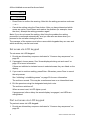
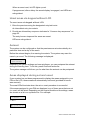
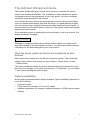
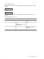
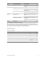
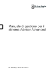
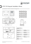
Advisor Advanced User Guide P/N 1068996 (EN) • REV F • ISS 29OCT14 Copyright Trademarks and patents © 2014 UTC Fire & Security Americas Corporation, Inc. All rights reserved. Interlogix, Advisor Advanced name and logo are trademarks of UTC Fire & Security. Other trade names used in this document may be trademarks or registered trademarks of the manufacturers or vendors of the respective products. Manufacturer UTC Fire & Security Americas Corporation, Inc. 3211 Progress Drive, Lincolnton, NC, 28092, USA Authorized EU manufacturing representative: UTC Fire & Security B.V. Kelvinstraat 7, 6003 DH Weert, Netherlands Version This document applies to the following Advisor Advanced firmware versions: ATSx000A(-IP): V024.024.128 ATSx500A(-IP): MR_1.0.27006 Certification Important: This product has not been designed to comply to EN 50134 and EN 54 norms. European Union directives UTC Fire & Security hereby declares that this device is in compliance with the applicable requirements and provisions of one or more of the Directives 1999/5/EC, 2014/30/EU and 2014/35/EU. For more information see www.utcfireandsecurity.com or www.interlogix.com. 2002/96/EC (WEEE directive): Products marked with this symbol cannot be disposed of as unsorted municipal waste in the European Union. For proper recycling, return this product to your local supplier upon the purchase of equivalent new equipment, or dispose of it at designated collection points. For more information see: www.recyclethis.info. Contact information Customer support www.utcfireandsecurity.com or www.interlogix.com www.utcfssecurityproducts.eu Content Important information iii Typographical conventions iii Important note iii Keypads and readers 1 Using your PIN and/or card to access the system 4 Duress 5 Door access 6 Set and unset the system 7 When to set 7 When to part set 7 When to unset 7 The time limit to leave the premises once set 7 The time limit when unset 8 Unset when there is an alarm 8 When you cannot set or unset 8 Set areas via LCD keypad 10 Part set areas via LCD keypad 10 Unset areas via LCD keypad 11 Set areas via keypad without LCD 11 Unset areas via keypad without LCD 12 Autoset 12 Areas displayed during set and unset 12 What to do when there is an alarm 14 What happens when there is an alarm 14 Who to contact when an alarm occurs 14 Viewing an alarm 15 Resetting an alarm 15 Acknowledging the alarm 15 Performing a walk test 15 Problems that can occur 16 The Advisor Advanced menu 17 How the menu option sections are organised in this manual 17 Option availability 17 Accessing menu 18 Advisor Advanced User Guide i Zones and fobs 19 Inhibiting / uninhibiting zones 20 Panel status 21 PIN 22 SMS and voice reporting 23 Service 24 Common key sequences 25 Common key sequences for LCD keypad 25 Common key sequences for keypad without LCD 26 Function keys 27 ii Advisor Advanced User Guide Important information This document includes an overview of the product and detailed instructions explaining how to use the Advisor Advanced system. To use this documentation effectively, you should have a basic knowledge of alarm systems. Read these instructions and all ancillary documentation entirely before operating this product. Typographical conventions This manual uses certain notational and typographical conventions to make it easier for you to identify important information. Table 1: Notational and typographical conventions Item Description Keys Capitalized, for example “press Enter”. Note Notes alert you to information that can save you time and effort. Caution Cautions identify conditions or practices that may result in damage to the equipment or other property. Check boxes let you indicate whether a particular option is available or not. The manager can provide details on the available options. Important note This manual provides information for all Advisor Advanced control panels in all variations. “Advisor Advanced control panel” refers to any variant of the Advisor Advanced, unless specifically stated otherwise. Table 2: List of ATSx000A(-IP) panel variants Model Enclosure Dimensions (mm) Weight (kg) ATS1000A-SM Metal 250 x 250 x 86 2.8 ATS1000A-MM Metal 315 x 388 x 85 5.2 ATS1000A-IP-MM Metal 315 x 388 x 85 5.2 ATS1000A-LP Plastic 257 x 400 x 112 2.6 ATS1000A-IP-LP Plastic 257 x 400 x 112 2.6 ATS2000A-MM Metal 315 x 388 x 85 5.2 ATS2000A-IP-MM Metal 315 x 388 x 85 5.2 Table 3: List of ATSx500A(-IP) panel variants Model Enclosure Dimensions (mm) Weight (kg) ATS1500A-SP Plastic 257 x 227 x 112 1.6 ATS1500A-IP-SP Plastic 257 x 227 x 112 1.6 ATS1500A-MM Metal 315 x 388 x 85 5.2 Advisor Advanced User Guide iii Model Enclosure Dimensions (mm) Weight (kg) ATS1500A-IP-MM Metal 315 x 388 x 85 5.2 ATS1500A-SM Metal 250 x 250 x 86 2.8 ATS1500A-IP-SM Metal 250 x 250 x 86 2.8 ATS1500A-LP Plastic 257 x 400 x 112 2.6 ATS1500A-IP-LP Plastic 257 x 400 x 112 2.6 ATS3500A-MM Metal 315 x 388 x 85 5.2 ATS3500A-IP-MM Metal 315 x 388 x 85 5.2 Notes • Not all variants may be available. • Weight does not include batteries. iv Advisor Advanced User Guide Keypads and readers Figure 1: ATS111xA keypad (1) Figure 2: ATS1135 keypad (2) !! (1) (3) (6) (4) (2) (10) (12) (25) (22) (13) (14) (21) (24) (6) (11) (9) (4) (3) 1 2 # (5) (6) (7) (8) (9) (10) A C (11) (12) (14) (17) (19) B 1 2 3 4 5 6 7 8 9 * 0 Menu Enter (13) (23) 1 .,’?! 2 abc 3 def 4 ghi 5 jkl 6 7 8 9 * 0 (16) (17)(15) tuv (19) (18) (7) (15) (16) # (18) 8 1 9 (20) 16 (1) AC mains LED Green on: AC mains supply on (2) Access LED Blue flashes: card read (3) Fault LED Yellow on: system fault active Yellow flashing: general alert (EN 50131) (4) Alarm LED Red on: alarm condition active (5) LCD display Displays messages (6) / Up Scroll up in the menus Change value Delete (7) ? / Help Show help Enable/disable word library Scroll text (ATS113x only) (8) Partset Part set an area Scroll text (ATS111x only) (9) F / Function Show active zones / faults Function key modifier Scroll text (ATS113x only) (10) On Full set an area (11) / Right Enter the selected menu Move cursor right (12) / Left Return to the previous menu Move cursor left (13) X / Clear Exit the current user function Volume control modifier (14) Off Unset an area Advisor Advanced User Guide 1 (15) / Down Scroll down in the menus Change value Backspace (16) Alphanumeric keys Keys 1 to 9, alphanumerical data (17) Menu, * Request entry to the menus (18) Enter, # Complete the step Enter the selected menu entry (19) 0 Key 0 Toggle selection (20) Area LEDs 1 to 16 On: area set Off: area unset Flashing: area alarm condition (21) Partset 1 Part set 1 of areas (22) Partset 2 Part set 2 of areas (23) A, B, C Programmable function keys (24) LED1 Programmable LED 1 (25) LED2 Programmable LED 2 Figure 3: ATS1190/ATS1192 readers Figure 4: ATS1197 reader with keypad (3) (1) (4) (5) (6) OFF ON (7) (8) (2) Figure 5: ATS1151/ATS1156 readers (3) (3) (6) (4) (5) (6) 1 2 3 1 2 3 4 5 6 4 5 6 7 8 9 7 8 9 * 0 # * 0 # (7) 2 (4) (5) (8) (7) (8) Advisor Advanced User Guide (1) Blue LED Access granted (2) Red LED On: area set Flashing: general alert (EN 50131) (3) Dual LED Green on: AC mains supply on Green flashing: AC mains supply off, or unlocked while unset Red on: all areas set Red flashing: unlocked while set (4) Yellow LED On: All zones are in normal state Flashing: general alert (EN 50131) (5) Red LED Flashing: alarm (6) Numeric keys Keys 0 to 9, numerical data (7) Off Unset an area (8) On Full set an area Advisor Advanced User Guide 3 Using your PIN and/or card to access the system You need a PIN and/or a card to use the Advisor Advanced system. A PIN is a unique number having between 4 and 10 digits. The manager of the security system has set up your user account with a PIN and/or card details. In addition, options have been assigned that allow you to perform specific tasks, such as set or unset the system. You can only access menu options that have been enabled for your user account. When you try to access an option that you are not authorised to access, you get the following error message: ERROR Access denied If you access the menu and do not press any key for three minutes, the system time out function automatically exits from the menu. It is good practice to exit the menu using the Clear button rather than using this time out facility. If someone else uses the menu before it times out, the option used is logged against your user account. 4 Advisor Advanced User Guide Duress The duress function activates a silent signal to alert security personnel. If you are asked, under threat, to breach your system security (for example, forced to unset the system), this function lets you do so while at the same time activating the system duress facility. However, your Advisor Advanced system must be programmed to use this function. You use a duress digit in conjunction with your PIN. There are three methods for entering a duress code. Table 4: Duress methods Option Description Example Increment last digit The duress code is your PIN with the last digit of your PIN incremented by one (1) Example: PIN = 1234, duress code = 1235. Available If the last digit of your PIN is 9, then the duress digit becomes 0. Example: PIN = 2349, duress code = 2340. Add last digit The duress code is a code Example: PIN = 1234, duress code with an additional digit “5” = 12345 at the end Add first digit The duress code is a code Example: PIN = 1234, duress code with an additional digit “5” = 51234 on the beginning To activate duress, provide an allowed key sequence indicated in “Common key sequences” on page 25. To reset the duress alarm, enter a valid PIN or card with PIN. Notes • If duress was activated under conditions that are no longer valid (a false alarm), and it has been reset, you must contact your central station company to ensure that they take no further action. • Using your PIN with the duress digit still activates the options configured for your user group. Advisor Advanced User Guide 5 Door access If programmed, it is possible to get access through a particular door using the keypad or the reader assigned to the door. Provide an allowed key sequence indicated in “Common key sequences” on page 25. 6 Advisor Advanced User Guide Set and unset the system When to set The security system should be set if you are the last person to leave the premises (or your area), for example at the end of the day. When set, any security device detecting intruders activates an alarm. When to part set In case you are still on the premises (or in your area) it is possible to perform a part set of it. For example, you can secure your garage using part set while you remain in the house. Notification to the central station may happen depending on system configuration settings. Contact your installer for more information. You can use part set for perimeter protection, for example when you secure your house at night but stay inside. You can move inside of the house, but if someone tries to enter without unset, this triggers an alarm. Notification to the central station may be sent depending on system configuration settings. Your installer can provide details. Depending on the keypad model, you may be prompted to choose an appropriate set to part set: 1>Part set 1 2 Part set 2 When to unset If the area you want to enter is set, you must first unset the alarm system before you can enter as otherwise you will trigger an alarm. Depending on system configuration you may be able to tell when an area is set because the LED on the keypad is lit red. If the armed display is enabled, only the Mains LED will be lit. Once a valid code is entered, the system status will be shown. In most cases an entry beeper sounds indicating that the system needs to be unset or an alarm will occur. The time limit to leave the premises once set Once you have set the system, you must leave the premises (or area) within a pre-set time (“exit time”) as otherwise you will set off the alarm. The manager of the system needs to inform everyone about this time limit. Normally, you will hear a beeper during the time allowed to leave the building. Make sure you know which route to take when leaving the premises. Advisor Advanced User Guide 7 The time limit when unset Once the system is set, you have to unset the area within a pre-set time (“entry time”) as otherwise you will set off the alarm. The manager of the system needs to inform everyone about this time limit. You will normally hear a beeper during the time allowed to unset. Note: There can be programmed an extended entry time. After the main entry time passes, the entry timer is extended for a programmed time period and a local alarm activates. See “Local alarm” on page 14 for more details. Unset when there is an alarm If there is an alarm condition while you are unsetting the system, the alarm is reset. You must then find out what caused the alarm and make sure it does not happen again. See “What to do when there is an alarm” on page 14. Unsetting while the system is in alarm is described in “Resetting an alarm” on page 15. When you cannot set or unset WARNING No access You might not be authorised to set/unset specific areas on the premises because: • Your keypad has been programmed to set/unset specific areas of the premises only. Make sure you know which keypad to use if there is more than one present of the premises. • Your PIN and/or card have been programmed to set/unset only specific areas of the premises. Make sure you know which areas you are authorised to set/unset. • Your alarm system might have more than one control panel. If so, each will have been programmed to set/unset only specific areas of the premises. Make sure you use the correct keypad for the areas you want to set/unset. Active zones You cannot set an area if it has a zone that is open, such as the magnetic contacts of a door or window. So, before setting, make sure that all doors and windows are properly closed. If a zone is open when you try to set, you get the message: CHECK SYSTEM Devices open 8 Advisor Advanced User Guide All the active zones are listed: 1 Zone active Zone 1 Setting the areas is now disallowed. If the indicated zones have to stay open (for example, you need to leave a window open), the problem may be resolved using one of the following methods: • Cancel the setting using the Clear button. Log on to the menu and inhibit the zone if it should remain active. See “Inhibiting / uninhibiting zones” on page 20 for more information. After active zone is inhibited, attempt the setting procedure again. • Inhibit the zone from the set menu. This is only allowed if you have the proper options available. It only works on zones that are allowed to inhibit. Press Off to inhibit. >1 Zone 1 ---------------Inhibited Alarms If any more zones are active, this step may be repeated. • Use forced set. You can activate forced set only if you have the proper options available. The system configuration also needs to include this option. Forced set is an automatic inhibiting of open zones and some faults. The conditions for inhibiting and uninhibiting items are configured in the system. The manager must inform users when they are allowed to use forced set. To activate forced set, press On. All open zones and faults are inhibited, and the appropriate warning is displayed. See “Inhibited zones and faults” below. Active faults CHECK SYSTEM Faults You cannot set an area if certain system faults are present. The list of faults preventing setting the system is defined by the installer. It is possible to temporarily disable these warnings in the same way as for active zones (see above). The manager must inform users whether or not they are authorized to disable faults in this way. Inhibited zones and faults If there are inhibited faults or zones, it is necessary to confirm information about it. WARNING Inhibited Advisor Advanced User Guide 9 All the inhibited zones and faults are listed: Inhibited Zone 1 Battery fault Inhibited • Press Enter to confirm the warning. After this the setting procedure continues. — or — • Cancel the setting using the Clear button. After you have determined which zones are active, check these and resolve the problem (for example, close the door). Attempt the setting procedure again. Note: If you do not cancel the setting, after fixing the problem the setting procedure is continued automatically, and you can raise an alarm when you proceed to the exit after closing the zone. The manager of the system must inform users which keypads they can use, and which areas they can set and unset. Set areas via LCD keypad To set areas via LCD keypad: 1. Provide an allowed key sequence indicated in “Common key sequences” on page 25. 2. If prompted, choose areas. See “Areas displayed during set and unset” on page 12 for more information. If there are inhibited or isolated zones in selected areas, they are listed on the display. 3. If you want to continue setting, press Enter. Otherwise, press Clear to cancel the set process. See “Inhibiting / uninhibiting zones” on page 20 for more information. The exit tone sounds. This may be a continuous tone or an intermittent tone. 4. Exit the premises using the designated entry/exit route. The exit tone switches off. When an area is set, its LED lights up red. If programmed, after a delay the armed display is engaged, and LEDs are extinguished. Part set areas via LCD keypad To part set areas via LCD keypad: 1. Provide an allowed key sequence indicated in “Common key sequences” on page 25. 10 Advisor Advanced User Guide 2. If prompted, choose the appropriate part set. 3. If prompted, choose areas. See “Areas displayed during set and unset” on page 12 for more information. If there are inhibited or isolated zones in selected areas, they are listed on the display. 4. If you want to continue setting, press Enter. Otherwise, press Clear to cancel the set process. See “Inhibiting / uninhibiting zones” on page 20 for more information. If programmed, the exit tone sounds. This may be a continuous tone or an intermittent tone. The exit tone switches off. When an area is partially set, its LED lights up red. If programmed, after a delay the armed display is engaged, and LEDs are extinguished. Unset areas via LCD keypad To unset areas via LCD keypad: 1. Enter the premises using the designated entry/exit route. An intermittent entry tone starts and the following prompt is displayed: Enter card/code to unset 2. Provide an allowed key sequence indicated in “Common key sequences” on page 25. 3. If prompted, choose areas. See “Areas displayed during set and unset” on page 12 for more information. The entry buzzer stops and the areas are unset. LEDs are extinguished, and the time and date is displayed. Set areas via keypad without LCD To set areas via keypad without LCD: 1. Provide an allowed key sequence indicated in “Common key sequences” on page 25. If the operation is not possible, the keypad beeps seven times. See “When you cannot set or unset” on page 8 for more information. The exit tone sounds. This may be a continuous tone or an intermittent tone. 2. Exit the premises using the designated entry/exit route. The exit tone switches off. Advisor Advanced User Guide 11 When an area is set, its LED lights up red. If programmed, after a delay the armed display is engaged, and LEDs are extinguished. Unset areas via keypad without LCD To unset areas via keypad without LCD: 1. Enter the premises using the designated entry/exit route. An intermittent entry tone starts. 2. Provide an allowed key sequence indicated in “Common key sequences” on page 25. The entry buzzer stops and the areas are unset. LEDs are extinguished. Autoset The system can be configured so that the premises are set automatically at a particular time and a day of the week. Before the autoset begins, the warning time starts. The system may warn the users by a sound. The following message is displayed: INFO Auto setting Depending on system settings and user privileges, you can postpone the autoset during the warning time. To do this, press Clear and authorize. The system manager will inform you for what time the autoset can be postponed. Areas displayed during set and unset If your system has not been programmed to display the areas assigned to your PIN on the LCD, those areas are automatically set/unset (provided all zones were normal). The area LEDs illuminate when the set or unset procedure is successful. If the areas assigned to your PIN are displayed, any of those areas that are set (or unset) will be listed. Depending on the keypad model and its settings, areas are shown as a list or a symbolic line. For example: 0> All 1 * Office — or — 1 2 3 4 5 6 7 8 █ [ ] √ x ? + + 12 Advisor Advanced User Guide Each area in the list has an indicator that describes its status. The following area statuses are available. Table 5: Area statuses and indicators for different keypads Area status List Symbolic line Ready to set Space √ Not ready to set ? ? Exit time x x Alarm ! Set * █ Part set 1 − [ Part set 2 = ] Selected + + (blinking) Depending on the type of the list, you now have the following options. Selecting areas in the list • To set or unset all areas, press 0, or select “0 All” from the list and press Enter. • To select or unselect an area, enter the area number, or select the area in the list and then press Enter or Right. • To set or unset the selected areas, press 0, or select “0+Selected” from the list and press Enter. • To cancel, press Clear. Selecting areas in the symbolic line All areas are selected by default. • To select or deselect all areas, press 0. • To select or unselect an area, enter the area number. • To set or unset the selected areas, press Enter. • To cancel, press Clear. Advisor Advanced User Guide 13 What to do when there is an alarm When there is an alarm, the LED of the area in alarm and the alarm LED flashes on the keypad. If the armed display is active, the LEDs start flashing when a user code has been entered. The time and date message is no longer displayed. An area can have several zones associated with it. When there is an alarm, it is important that you know exactly which zone is causing the alarm so that you can quickly deal with it. What happens when there is an alarm There are different types of alarm and they occur under different situations. Alarm An alarm is raised if: • The area is set and one of its zones has been activated. For example, a door lock has been forced open causing a siren to sound. • The area is unset and a 24 Hour zone was activated. Examples: a hold-up button is activated, or a tamper switch is open. The exact type of alarm signal depends on how the system has been programmed (strobes, sirens etc.) The LED on the keypad flashes quickly. The area LED on the panel identifies the location of the alarm. When programmed, the alarm is sent to the central station. Local alarm The alarm is only heard inside the premises and is dealt with locally. An internal siren activates. The area LED on keypad flashes (depending on how it has been programmed). The keypad beeps until someone acknowledges the alarm at the keypad. It occurs, for example, when a zone programmed as fire door has been activated. The central station does not need to be contacted. System alarm This alarm can occur at any time. The exact type of alarm signal depends on how the system has been programmed (strobes, sirens etc.) It occurs when the security equipment (such as the panel) has been tampered with, or detects a fault. You can only reset a system alarm if your PIN has been authorised to do so, and only after the fault is restored. When programmed, the central station is contacted automatically by the system. Who to contact when an alarm occurs Contact the manager of your security system when an alarm occurs. 14 Advisor Advanced User Guide Viewing an alarm After disarm, all the alarms are listed on the screen. Alarm Pending >0< Zone 1 Pending >0< The first screen shows the type of the alarm. The second shows the source of the alarm. The second line shows if there are more alarms for this source. Resetting an alarm To switch off sirens or bells, you must unset the appropriate area. If an alarm is active, the reset procedure is the same as for a standard unset. After the system is unset, you are prompted to acknowledge the alarms. This is possible only if the problem has been resolved. Acknowledging the alarm If you are permitted, you can acknowledge the alarm by pressing Off. The alarm cannot be acknowledged if its cause is still active, for example, if there is a zone tamper. The fault should be fixed prior to acknowledging the alarm caused by this fault. All alarms must be acknowledged. A counter during the alarm acknowledgement process indicates the number of outstanding alarms to still be acknowledged. If you don't acknowledge the alarms after the unset, you are prompted to do so before next set or after the next unset, until all alarms are acknowledged. Performing a walk test If the system is programmed for user walk tests, sometimes while setting the area, the system may ask you to perform the area walk test. To pass the walk test, you need to go to all the zones displayed. The system lists all zones still to be tested. The manager of the alarm system must inform users which zones must be tested to pass the walk test. The necessity of the walk test depends on: • System settings • Activity of the programmed zones in last 4 hours You can perform the walk test manually using “8.2 Walk test” menu (described on page 24). Advisor Advanced User Guide 15 Problems that can occur There is a faulty zone A faulty zone continues to cause an alarm until it is isolated from the system. Your manager is allowed to isolate the faulty zone if necessary. As soon as the faulty zone is isolated or the problem has been resolved, the alarm is reset automatically. Your PIN does not work when you try to acknowledge an alarm There are two possible reasons why your PIN may not work when you attempt to acknowledge an alarm: • You can only acknowledge an alarm for an area if your PIN is assigned to it. If it is not and you try to acknowledge an alarm, you might set/unset the area instead. • You cannot acknowledge a system alarm unless your PIN is authorised to do so. The keypad does not respond to key presses The keypad may not respond to key presses even when there is no fault in the system. The keypad is locked after a wrong PIN is entered three or more times. When you press a key on a locked keypad, it beeps seven times. After 2 minutes the keypad becomes available again. 16 Advisor Advanced User Guide The Advisor Advanced menu The Advisor Advanced system uses a menu structure to present the various options and commands available. The availability of these depends on system configuration and on the permissions in your user group. You may not always see all the items described in this manual. If you access the menu and do not press any key for three minutes, the system time out function automatically exits from the menu. It is good practice to make sure you exit the menu using the Clear button rather than this time out facility. If someone else uses the menu before it times out, the options used will be logged against your user account. If you attempt to select an option that is not authorised in your user account, the display shows the message: ERROR Access denied Although you might be authorised to access a menu option, you might not be allowed to access all the information it provides. You are only allowed to access information for the areas assigned to your user account. How the menu option sections are organised in this manual Menu options are numbered in the Advisor Advanced system. This numbering system is also used in this manual, so menu option 1 “Inhibit zones” is topic “1 Inhibit zones”. The menu number also refers to the key sequence that can be pressed to enter the menu. For example, if you want to enter menu “7.2 Walk test”, you can press 7, then 2 after entering the menu system. Option availability Not all options described below may be available. Option availability depends on one of the following: • • • Firmware version Panel model (for example, IP or non-IP model) Installed expansions (for example, wireless expander or GSM communication module) Advisor Advanced User Guide 17 Accessing menu Before commencing, ensure that the welcome or status screen is shown on the display. UTC F&S TUE 29 Apr 08:55 — or — 1 2 3 4 5 6 7 8 █ [ ] √ x ? + + Provide an allowed key sequence indicated in “Common key sequences” on page 25. From the display you can now: Option Action Result Change the selection Press Up or Down Select previous or next menu option Enter the menu option Enter menu option number — or — Press Enter or Right to enter the selected one Jump to a specific menu option Show help Press Help Display a description of the selected menu entry (if available) Exit a menu option Press Left or Clear Exit the menu option 18 Advisor Advanced User Guide Zones and fobs 1 Zones & Fobs 1>Inhibit zones 2 Camera menu The zones and fobs menu allows inhibiting zones and performing user operations on cameras. Advisor Advanced User Guide 19 Inhibiting / uninhibiting zones 1.1 Inhibit zones The Inhibit function is used to inhibit zones and exclude them from the security system until the next unset. There may be occasions when you want to inhibit a zone. For example, if you want to leave a window open when the system is set. By inhibiting the zone associated with the window, when you set the system you will not activate an alarm. Note: It is also possible to inhibit active zones while setting an area. See “Active zones” on page 8 for more information. Enter the “Inhibit zones” menu to inhibit or uninhibit zones. What happens next depends on whether or not there are active zones: All zones are normal You can inhibit normal zones if you know their zone number. 1>Zone 1 Uninhibited 1. Press Up or Down to scroll through the zones. 2. Press the zone number, or use Enter to select a zone. 3. Change the zone state using Up and Down. 4. Confirm the changes by pressing Enter. 5. Press Clear twice to exit programming. Active zones When one or more zones are active, the system displays: 1>Zone 1 Active The active zones are listed one by one. 1. Press the Up and Down buttons to scroll through the zones. 2. To inhibit the selected zone, press Enter. The confirmation is displayed: 1>Zone 1 Inhibited 3. If you do not have rights to inhibit the selected zone, the following warning is displayed: WARNING No access 4. Press Clear to exit programming. 20 Advisor Advanced User Guide Panel status 4 Panel status The "Panel status" function lists zones that are in alarm or tamper alarm, zones that are inhibited or active, plus system alarms. There are menu options that display each of these conditions separately. However, this option can be used to check on all zones that need attention. If you are allowed, you can see the panel current status using the “4 Panel status” menu. The following data can be viewed: Table 6: Panel status data Option Description 4.1 View open zones Displays zones that are not in normal state. The top line shows the zone that is not in normal state. The bottom line shows the zone status. 4.2 Alarms Displays and lets you to acknowledge pending alarms. 4.3 Faults Displays active faults. Advisor Advanced User Guide 21 PIN 5 Change PIN 1>PIN ********** If you are allowed, you can change your PIN using Change PIN menu. The PIN policy in the Advisor Advanced system can be configured in one of the following ways: • PINs are generated by the system. The user can request a new PIN generation, but PINs cannot be entered manually or edited. The PIN is generated when pressing Enter in this menu. Once generated the code is then displayed. • PINs are entered manually. If you are allowed to do it, you can enter the unique PIN you want to have. Pressing Enter lets you enter or edit a PIN. To confirm the PIN, enter it again. PINs must be unique. A PIN cannot be assigned to more than one user. The system does accept entry of PINs that are already in use. 22 Advisor Advanced User Guide SMS and voice reporting 6 SMS and Voice 1>User phone None The SMS and Voice menu contains configuration menus for SMS and voice reporting. This menu allows you to change only your own settings. 6.1 User phone 1 User phone > < The User phone menu allows you to set your personal phone number. 6.2 SMS reporting 2 SMS reporting Off The SMS reporting menu allows you to enable or disable SMS reporting to you. This option is editable only if you belong to a user group that has SMS reporting privilege enabled. 6.3 SMS control 3 SMS control Disable The SMS control menu allows you to see whether you have a possibility to send SMS commands. System manager will provide you with the list of SMS commands you can use. Advisor Advanced User Guide 23 Service 8 Service menu The Service menu allows performing the maintenance tasks described below. 8.2 Walk test Walk test in progress Walk test allows the user to test all detectors in the selected areas. To perform the walk test: 1. Enter the menu. Next, you are prompted to choose between total and reduced walk test. Walktest scope >Total< The following options are available: - Total: Standard walk test. All appropriate zones are tested. - Reduced: Reduced walk test. This test is limited only zones that were not active recently, during last 4 hours, or since the last set. Choose a walk test scope and press Enter. The display lists all zones to be tested. 1>Zone 1 Need Active 2. Walk along all detection points and make sure the detector is activated either by walking in front of it or by opening a door or window. Each activated zone is removed from the list on the display. 3. Return to the keypad and verify the result. If the test is passed, the following message is displayed: Walk test OK Press Enter Otherwise, there still is a list of untested zones. Contact the installer if you are unable to pass the walk test. See also “Performing a walk test” on page 15 for more information. 24 Advisor Advanced User Guide Common key sequences See “Set and unset the system” on page 7. The authorization method depends on system settings. Your manager can inform you what method should be used for authorization. Common key sequences for LCD keypad Table 7: Common key sequences for LCD keypad Action Programmed method Key sequence [1] Set Set with key On Set with PIN On, PIN, Enter PIN, On Card On, card 3 x card On, card, PIN, Enter Card, PIN, On Off, PIN, Enter Set with card Set with card and PIN Unset Unset with PIN PIN Unset with card Unset with card and PIN PIN, Off Card Off, card Off, card, PIN, Enter Card, PIN, Off Card, PIN Part set Part set with key Partset Part set with PIN Partset, PIN, Enter PIN, Partset Card Partset, card 3 x card Partset, card, PIN, Enter Card, PIN, Partset Door access with PIN PIN, Fnter Door access with card Card Door access with card and PIN Card, PIN, Enter Part set with card Part set with card and PIN Door access Advisor Advanced User Guide 25 Action Programmed method Key sequence [1] Menu access Menu access with PIN Menu, PIN, Enter PIN, Menu Menu access with card Menu, card Menu access with card and PIN Menu, card, PIN, Enter Card, PIN, Menu Any set key (On / Off / Partset), duress code, Enter Duress code, any set key Any set key (On / Off / Partset), duress code, card, Enter Card, duress code, any set key Increase volume X + Right Decrease volume X + Left Panic Panic alarm 1+3 Fault list Display fault list Function, Function Alarm list Display alarm list Enter, Enter Duress Duress with PIN Duress with card and PIN Change keypad buzzer volume [1] Availability must be defined by the manager. See also “Areas displayed during set and unset” on page 12. Common key sequences for keypad without LCD Table 8: Common key sequences for keypad without LCD Action Programmed method Key sequence [1] Set Set with PIN On, PIN, On Set with card Card On, card 3 x card On, card, PIN, On Card, PIN, On Off, PIN, On PIN PIN, Off Card Off, card Off, card, PIN, On Card, PIN, Off Set with card and PIN Unset Unset with PIN Unset with card Unset with card and PIN Card, PIN 26 Advisor Advanced User Guide Action Programmed method Key sequence [1] Part set Part set with card Card 3 x card Door access with PIN Any digit, PIN, On Door access with card Card Any digit, card Any digit, card, PIN, On Card, PIN, On Any set key (On / Off), duress code, Enter Duress code, any set key Any set key (On / Off), duress code, card, Enter Card, duress code, any set key 1+3 Door access Door access with card and PIN Duress Duress with PIN Duress with card and PIN Panic Panic alarm [1] Availability must be defined by the manager. When a PIN can be entered, the keypad beeps twice and flashes the red and green LEDs. When an operation fails the keypad beeps seven times. See “When you cannot set or unset” on page 8 for more information. Function keys Table 9: Function keys Action [1] Key [1] A B C F1 (F + 1) F2 (F + 2) F3 (F + 3) F4 (F + 4) [1] Functionality and availability must be defined by the manager. Advisor Advanced User Guide 27 28 Advisor Advanced User Guide