1
User Guide
Broadcom NetXtreme 57XX
November 2012
BROADCOM NETLINK®/NETXTREME® 57XX USER GUIDE
•
•
Introduction
•
Functionality and Features
•
Virtual LANs
•
Teaming
Installing the Driver Software
•
Windows Driver Software
•
NDIS2 Driver Software
•
ODI Driver Software
•
Broadcom Boot Agent Driver Software
•
Linux Driver Software
•
Installing Management Applications
•
Using Broadcom Advanced Control Suite
•
Specifications
•
Regulatory Information
•
User Diagnostics
•
Troubleshooting
Information in this document is subject to change without notice.
© 2012 Broadcom Corporation. All rights reserved.
This document is protected by copyright and is distributed under licenses restricting its use, copying, distribution, and
decompilation. No part of this document may be reproduced in any form by any means without prior written authorization of
Broadcom Corporation. Documentation is provided as is without warranty of any kind, either express or implied, including
any kind of implied or express warranty of non-infringement or the implied warranties of merchantability or fitness for a
particular purpose.
Broadcom Corporation reserves the right to make changes without further notice to any products or data herein to improve
reliability, function, or design. Information furnished by Broadcom Corporation is believed to be accurate and reliable.
However, Broadcom Corporation does not assume any liability arising out of the application or use of this information, nor
the application or use of any product or circuit described herein, neither does it convey any license under its patent rights or
the rights of others.
Broadcom, the pulse logo, Connecting everything, the Connecting everything logo, NetLink, NetXtreme,
Ethernet@Wirespeed, LiveLink, and Smart Load Balancing are among the trademarks of Broadcom Corporation and/or its
affiliates in the United States, certain other countries, and/or the EU. Microsoft and Windows are trademarks of Microsoft
Corporation. Linux is a trademark of Linus Torvalds. NetWare is a trademark of Novell Corporation. Intel is a trademark of
Intel Corporation. Magic Packet is a trademark of Advanced Micro Devices, Inc. Red Hat is a trademark of Red Hat, Inc. PCI
Bro adco m Co rp or atio n
Document
INGDTM154-CDUM100-R
Page 1
Broadcom NetXtreme 57XX
User Guide
November 2012
Express is a trademark of PCI-SIG. Any other trademarks or trade names mentioned are the property of their respective
owners.
Last revised: November 2012
INGDTM154-CDUM100-R
Bro adco m C orp or atio n
Page 2
Document
INGDTM154-CDUM100-R
User Guide
Broadcom NetXtreme 57XX
November 2012
F u nc t i o na li t y a n d F e a tu r e s : B ro a d c o m
Ne tLink ® / N e tX t r e m e ® 5 7X X Use r Gu i de
•
Functionality and Features
•
Supported Operating Systems
•
Network Link and Activity Indication
FUNCTIONALITY AND FEATURES
FUNCTIONAL DESCRIPTION
Broadcom NetXtreme® Gigabit Ethernet adapters connect a PCI Express™ compliant computer to a Gigabit Ethernet
network. The network adapter incorporate a technology that transfers data at a maximum rate of 1 gigabit per second—10
times the rate of Fast Ethernet adapters.
FEATURES
The following is a list of the Broadcom network adapter features for all supported operating systems. For features specific
to your NetLink/NetXtreme network adapter, see Table 1.
•
Gigabit Ethernet (IEEE Std 802.3-1999)
•
Logical Link Control (IEEE Std 802.2)
•
Flow Control (IEEE Std 802.3x)
•
Standard Ethernet frame size (1518 bytes)
•
Layer-2 Priority Encoding (IEEE 802.1p)
•
High-speed on-chip RISC processor
•
Adaptive interrupt frequency
•
Up to four classes of service (CoS)
•
Up to four send rings and receive rings
•
Integrated 96 KB frame buffer memory
•
GMI/MII management interface
•
Statistics for SNMP MIB II, Ethernet-like MIB, and Ethernet MIB (IEEE Std 802.3z, Clause 30)
•
Four unique MAC unicast addresses
•
Support for multicast addresses via 128 bits hashing hardware function
•
Serial EEPROM or serial NVRAM flash memory
•
Supports PXE 2.1 specification (Linux Red Hat PXE Server, Windows Server 2003, Intel APITEST, DOS UNDI)
•
JTAG support
•
PCI Power Management Interface (v1.1)
•
PCI Express™ v1.0A, x1 or greater
Bro adco m Co rp or atio n
Document
INGDTM154-CDUM100-R
Functionality and Features: Broadcom NetLink®/NetXtreme® 57XX User Guide
Page 3
Broadcom NetXtreme 57XX
User Guide
November 2012
•
ACPI and Wake on LAN support
•
64-bit BAR support
•
EM64T processor support
•
3.3 V/1.8 V CMOS with 5V tolerant I/Os
•
Self boot
•
Receive Side Scaling (RSS)
Bro adco m C orp or atio n
Page 4
Functionality and Features
Document
INGDTM154-CDUM100-R
User Guide
Broadcom NetXtreme 57XX
November 2012
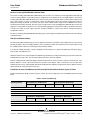
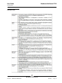
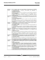
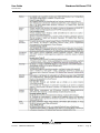
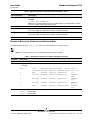
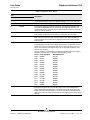
Table 1: Feature vs. Network Adapter Family
Feature
NetLink
NetXtreme
Base Drivers
Flow Control
X
X
Jumbo Frames
—
X
PCI Hot Plug
Xb
X
Unattended Install
X
X
Auto-Negotiate
X
X
802.1p (priority encoding)
X
X
Wake on LAN (WOL)
X
X
LSO IPv4
LSO IPv6
a
UDP/IP Checksum Offload IPv4 (tx and rx)
a
UDP/IP Checksum Offload IPv6 (tx only)
TCP/IP Checksum Offload IPv4 (tx and rx)
X
X
X
X
X
X
X
X
X
X
X
X
IPsec Task Offload
—
X
TPM 1.1b
—
Xc
TPM 1.2
—
X
—
X
TCP/IP Checksum Offload IPv6 (tx
only)a
Broadcom Advanced Control Suite (BACS)
Power Management
Vital Sign
—
X
Diagnostics
X
X
Cable Diagnostic
—
X
Selective Teaming
—
X
Teaming Configuration
—
X
Teaming Statistics
—
X
Statistics
—
X
Network Test
—
X
—
X
Broadcom Advanced Server Program (BASP)
SLB
Generic Trunking
—
X
Link Aggregation
—
X
Failover
—
X
LSO
—
X
Probe Packets
—
X
VLANs
—
X
Clockrun
—
X
Receive Side Scaling (RSS)
—
X
Self Boot
X
X
Miscellaneous
Bro adco m Co rp or atio n
Document
INGDTM154-CDUM100-R
Functionality and Features
Page 5
Broadcom NetXtreme 57XX
User Guide
November 2012
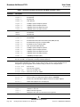
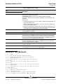
Table 1: Feature vs. Network Adapter Family
Feature
NetLink
NetXtreme
Alert Standard Format (ASF) 1.0
—
X
Alert Standard Format (ASF) 2.0
—
X
TruManage™
—
X
UMP
—
X
IPMI Passthrough
—
X
a.Not on all NetLink and NetXtreme network adapters.
b.Not on all NetLink network adapters.
c.Not on all NetXtreme network adapters.
Power Management
Wake on LAN (Magic Packet, Wake Up Frame, specific pattern) is supported at 10/100 Mbps operation only.
Note: Adapter speed connection when the system is down waiting for a wake-up signal is either 10 Mbps or 100
Mbps, but can return to 1000 Mbps when the system is up and running if connected to a 1000 Mbps capable switch.
Systems intending to use Wake on LAN (WOL) should be connected to a switch capable of both 1000 and 10/100
Mbps speeds.
Adaptive Interrupt Frequency
The adapter driver intelligently adjusts host interrupt frequency based on traffic conditions, to increase overall application
throughput. When traffic is light, the adapter driver interrupts the host for each received packet, minimizing latency. When
traffic is heavy, the adapter issues one host interrupt for multiple, back-to-back incoming packets, preserving host CPU
cycles.
Dual DMA Channels
The PCI interface on Broadcom NetXtreme Gigabit Ethernet adapters contains two independent DMA channels for
simultaneous read and write operations.
32-Bit or 64-Bit PCI Bus Master
Compliant with PCI Local Bus Rev 2.3, the PCI interface on Broadcom NetXtreme Gigabit Ethernet adapters is compatible
with both 32-bit and 64-bit PCI buses. As a bus master, the adapter requests access to the PCI bus, instead of waiting to be
polled.
ASIC with Embedded RISC Processor
The core control for Broadcom NetXtreme Gigabit Ethernet adapters resides in a tightly integrated, high-performance ASIC.
The ASIC includes a RISC processor. This provides the flexibility to add new features to the card and adapt it to future
network requirements through software downloads. This also enables the adapter drivers to exploit the built-in host offload
functions on the adapter as host operating systems are enhanced to take advantage of these functions.
Bro adco m C orp or atio n
Page 6
Functionality and Features
Document
INGDTM154-CDUM100-R
User Guide
Broadcom NetXtreme 57XX
November 2012
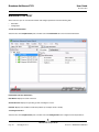
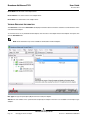
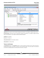
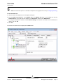
Broadcom Advanced Control Suite
Broadcom Advanced Control Suite (BACS) is an integrated utility that provides useful information about each network
adapter that is installed in your system. The BACS utility also enables you to perform detailed tests, diagnostics, and analysis
on each adapter, as well as to modify property values and view traffic statistics for each adapter. See “Using Broadcom
Advanced Control Suite for detailed information and instructions.
SUPPORTED OPERATING SYSTEMS
Broadcom NetXtreme Gigabit Ethernet adapters have software support for the following operating systems:
•
Microsoft® Windows® XP Family
•
Microsoft® Windows® Vista™ Family
•
Microsoft® Windows® 7 Family
•
Microsoft® Windows® 8 Family
•
Linux® (32-bit and 64-bit extended)
•
MS-DOS®
•
NetWare®
NETWORK LINK AND ACTIVITY INDICATION
The state of the network link and activity is indicated by the port LEDs adjacent to the RJ-45 connector, as described in
Table 2. Broadcom Advanced Control Suite also provides information about the status of the network link and activity (see
“Vital Sign”).
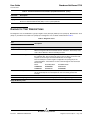
Table 2: Network Link and Activity Indicated by the Port LEDs
Port LED
LED Appearance
Network State
Link LED
Off
No link (cable disconnected)
Continuously illuminated
Link
Off
No network activity
Illuminated and blinking
Network activity
Activity LED
Bro adco m Co rp or atio n
Document
INGDTM154-CDUM100-R
Supported Operating Systems
Page 7
Broadcom NetXtreme 57XX
User Guide
November 2012
Bro adco m C orp or atio n
Page 8
Network Link and Activity Indication
Document
INGDTM154-CDUM100-R
User Guide
Broadcom NetXtreme 57XX
November 2012
Te ami n g: Broa dc om NetL in k ® /N etXtrem e ® 5 7 X X
U s e r G ui de
•
Broadcom Advanced Server Program Overview
•
Load Balancing and Fault Tolerance
BROADCOM ADVANCED SERVER PROGRAM OVERVIEW
Adapter teaming allows you to group any available network adapters together to function as a team, the benefit of which
enables membership to VLANs on different subnets. You also can add virtual LANs (VLANs) to a team, which enables you
to add multiple virtual adapters that are on different subnets. The benefit of adding VLANs to a team, is that each virtual
adapter can belong to multiple subnets. With a VLAN, you can couple the functionality of load balancing for the load balance
members, and with the capability of employing a failover adapter.
Broadcom Advanced Server Program (BASP) is the Broadcom teaming software for Windows Server 2003, Windows 8,
Windows 7, Vista, Windows XP, and NetWare operating systems. For Windows operating systems, BASP runs within the
BACS utility. For NetWare operating systems, teams are configured by loading BASP with all the necessary frames for the
team (see “Configuring Teaming”).
Note: BASP is not supported on all Broadcom network adapters.
BASP supports four types of load balancing teams:
•
Smart Load Balancing™ and Failover
•
Link Aggregation (802.3ad)
•
Generic Trunking (FEC/GEC)/802.3ad-Draft Static
•
SLB (Auto-Fallback Disable)
Note: Enabling Windows Server 2003 built-in bridging is not advisable when you are using teaming software.
LOAD BALANCING AND FAULT TOLERANCE
Teaming provides traffic load balancing and fault tolerance (redundant adapter operation in the event that a network
connection fails). When multiple adapters are installed in the same system, they can be grouped into teams, creating a virtual
adapter.
A team can consist of one to eight network interfaces, and each interface can be designated as a primary interface or a
standby interface (standby interfaces can be used only in a Smart Load Balancing™ and Failover (SLB) or SLB (AutoFallback Disabled) type of team, and only one standby interface can be designated per SLB team). If traffic is not identified
on any of the adapter team member connections due to failure of the adapter, cable, switch port, or switch (where the teamed
adapters are attached to separate switches), the load distribution is reevaluated and reassigned among the remaining team
Bro adco m Co rp or atio n
Document
INGDTM154-CDUM100-R
Teaming: Broadcom NetLink®/NetXtreme® 57XX User Guide
Page 9
Broadcom NetXtreme 57XX
User Guide
November 2012
members. In the event that all of the primary adapters are down, the hot standby adapter becomes active. Existing sessions
are maintained and there is no impact on the user.
Types of Teams
The available types of teams for the supported operating systems are shown in the following table:
Table 1: Types of Teams
Operating System
Available Types of Teams
Windows Server 2003
Windows 8
Windows 7
Windows XP
Windows Vista
Smart Load Balancing and Failover
Link Aggregation (802.3ad)
Generic Trunking (FEC/GEC)/802.3ad-Draft Static
SLB (Auto-Fallback Disable)
Linux
Team adapters using the bonding kernel module and a
channel bonding interface: Information on channel bonding
can be found at http://www.redhat.com/docs/manuals/
enterprise/RHEL-3-Manual/ref-guide/s1-modulesethernet.html.
NetWare
Smart Load Balancing
Link Aggregation (802.3ad)
Generic Trunking
Smart Load Balancing™ and Failover
Smart Load Balancing™ and Failover is the Broadcom implementation of load balancing based on IP flow. This feature
supports balancing IP traffic across multiple adapters (team members) in a bidirectional manner. This type of team provides
automatic fault detection and dynamic failover to other team member or to a hot standby member. This is done independently
of layer 3 protocol (IP, IPX, NetBEUI); rather, it works with existing layer 2 and layer 3 switches. No switch configuration
(such as trunk, link aggregation) is necessary for this type of team to work.
Notes:
•
If you do not enable LiveLink™ when configuring teams, disabling Spanning Tree Protocol (STP) at the switch
is recommended. This minimizes the downtime due to spanning tree loop determination when failing over.
LiveLink mitigates such issues.
•
IPX balances only on the transmit side of the team; other protocols are limited to the primary adapter.
•
If a team member is linked at 1000 Mbit/s and another team member is linked at 100 Mbit/s, most of the traffic
is handled by the 1000 Mbit/s team member.
Link Aggregation (802.3ad)
This mode supports link aggregation and conforms to the IEEE 802.3ad (LACP) specification. Configuration software allows
you to dynamically configure which adapters you want to participate in a given team. If the link partner is not correctly
configured for 802.3ad link configuration, errors are detected and noted. With this mode, all adapters in the team are
configured to receive packets for the same MAC address. The outbound load-balancing scheme is determined by our BASP
driver. The team link partner determines the load-balancing scheme for inbound packets. In this mode, at least one of the
link partners must be in active mode.
Bro adco m C orp or atio n
Page 10
Teaming: Broadcom NetLink®/NetXtreme® 57XX User Guide
Document
INGDTM154-CDUM100-R
User Guide
Broadcom NetXtreme 57XX
November 2012
Generic Trunking (FEC/GEC)/802.3ad-Draft Static
The Generic Trunking (FEC/GEC)/802.3ad-Draft Static type of team is very similar to the Link Aggregation (802.3ad) type
of team in that all adapters in the team need to be configured to receive packets for the same MAC address. The Generic
Trunking (FEC/GEC)/802.3ad-Draft Static) type of team, however, does not provide LACP or marker protocol support. This
type of team supports a variety of environments in which the adapter link partners are statically configured to support a
proprietary trunking mechanism. For instance, this type of team could be used to support Lucent's OpenTrunk or Cisco's
Fast EtherChannel (FEC). Basically, this type of team is a light version of the Link Aggregation (802.3ad) type of team. This
approach is much simpler, in that there is not a formalized link aggregation control protocol (LACP). As with the other types
of teams, the creation of teams and the allocation of physical adapters to various teams is done statically through user
configuration software.
The Generic Trunking (FEC/GEC/802.3ad-Draft Static) type of team supports load balancing and failover for both outbound
and inbound traffic.
SLB (Auto-Fallback Disable)
The SLB (Auto-Fallback Disable) type of team is identical to the Smart Load Balance and Fail Over type of team, with the
following exception—when the standby member is active, if a primary member comes back on line, the team continues using
the standby member, rather than switching back to the primary member.
If any primary adapter assigned to a team is disabled, the team functions as a Smart Load Balancing and Failover type of
team in which auto-fallback occurs.
All primary interfaces in a team participate in load-balancing operations by sending and receiving a portion of the total traffic.
Standby interfaces take over in the event that all primary interfaces have lost their links.
Failover teaming provides redundant adapter operation (fault tolerance) in the event that a network connection fails. If the
primary adapter in a team is disconnected because of failure of the adapter, cable, or switch port, the secondary team
member becomes active, redirecting both inbound and outbound traffic originally assigned to the primary adapter. Sessions
will be maintained, causing no impact to the user.
Limitations of Smart Load Balance and Fail Over/SLB (Auto-Fallback Disable) Types of Teams
Smart Load Balancing™ (SLB) is a protocol-specific scheme. The level of support for IP, IPX, and NetBEUI protocols is listed
below.
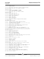
Table 2: Smart Load Balancing
Operating System
Windows Server 2003
Failover/Fallback—All Broadcom
Failover/Fallback—Multivendor
IP
IPX
NetBEUI
IP
IPX
NetBEUI
Y
Y
N/S
Y
N
N/S
Windows XP
Y
Y
Y
Y
N
N
NetWare 5.1/6.5
Y
Y
N/S
Y
N
N/S
Red Hat Linux 3 and 4
Y
N/S
N/S
Y
N/S
N/S
Load Balance—All Broadcom
Load Balance—Multivendor
IP
IPX
NetBEUI
IP
IPX
NetBEUI
Windows Server 2003
Y
Y
N/S
Y
N
N/S
Windows XP
Y
Y
Y
Y
N
N
Bro adco m Co rp or atio n
Document
INGDTM154-CDUM100-R
Teaming: Broadcom NetLink®/NetXtreme® 57XX User Guide
Page 11
Broadcom NetXtreme 57XX
User Guide
November 2012
Table 2: Smart Load Balancing
Operating System
Failover/Fallback—All Broadcom
Failover/Fallback—Multivendor
NetWare 5.1/6.5
Y
Y
N/S
Y
Y
N/S
Red Hat Linux 3 and 4
Y
N/S
N/S
Y
N/S
N/S
Legend:
Y = yes
N = no
N/S = not supported
Drivers for third-party network adapters must be Netware Event Service Layer (NESL) compliant for NetWare to be faulttolerant and load-balanced in a multivendor team.
The Smart Load Balancing type of team works with all Ethernet switches without having to configure the switch ports to any
special trunking mode. Only IP traffic is load-balanced in both inbound and outbound directions. IPX traffic is load-balanced
in the outbound direction only. Other protocol packets are sent and received through one primary interface only. Failover for
non-IP traffic is supported only for Broadcom network adapters. The Generic Trunking type of team requires the Ethernet
switch to support some form of port trunking mode (for example, Cisco's Gigabit EtherChannel or other switch vendor's Link
Aggregation mode). The Generic Trunking type of team is protocol-independent, and all traffic should be load-balanced and
fault-tolerant.
Note: If you do not enable LiveLink™ when configuring teams, disabling Spanning Tree Protocol (STP) at the
switch is recommended. This minimizes the downtime due to the spanning tree loop determination when failing
over. LiveLink mitigates such issues.
LiveLink™ Functionality
LiveLink™ functionality is a feature of BASP that is available only for the Smart Load Balancing™ and Failover type of
teaming. The purpose of LiveLink is to detect link loss beyond the switch and to route traffic only through team members that
have a live link. This function is accomplished though the teaming software. The teaming software periodically probes
(issues a link packet from each team member) one or more specified target network device(s). The probe target(s) responds
when it receives the link packet. If a team member does not detect a response within a specified amount of time after a
specified number of retries, the teaming software discontinues passing traffic through that team member. Later, if that team
member begins to detect a response from a probe target, this indicates that the link has been restored, and the teaming
software automatically resumes passing traffic through that team member. LiveLink works only with TCP/IP.
LiveLink™ functionality is supported in both 32-bit and 64-bit Windows operating systems, but is not supported in NetWare
systems. See the Channel Bonding documentation for similar functionality in Linux Channel Bonding (see http://
www.redhat.com/docs/manuals/enterprise/RHEL-3-Manual/ref-guide/s1-modules-ethernet.html).
Teaming and Large Send Offload/Checksum Offload Support
Large Send Offload (LSO) and Checksum Offload are automatically enabled for a team only if LSO and Checksum Offload
are supported and configured on all members of a team.
Bro adco m C orp or atio n
Page 12
Teaming: Broadcom NetLink®/NetXtreme® 57XX User Guide
Document
INGDTM154-CDUM100-R
User Guide
Broadcom NetXtreme 57XX
November 2012
Vir t ua l L AN s: Broa dc om NetL i nk ® /NetXtre me ®
5 7X X Use r Gu i de
•
VLAN Overview
•
Adding VLANs to Teams
VLAN OVERVIEW
Virtual LANs (VLANs) allow you to split your physical LAN into logical parts, to create logical segmentation of workgroups,
and to enforce security policies for each logical segment. Each defined VLAN behaves as its own separate network with its
traffic and broadcasts isolated from the others, increasing bandwidth efficiency within each logical group. Up to 64 VLANs
(63 tagged and 1 untagged) can be defined for each Broadcom adapter on your system, depending on the amount of
memory available in your system.
Note: VLANs are not supported on all Broadcom network adapters.
VLANs can be added to a team to allow multiple VLANs with different VLAN IDs. A virtual adapter is created for each VLAN
added.
Although VLANs are commonly used to create individual broadcast domains and/or separate IP subnets, it is sometimes
useful for a server to have a presence on more than one VLAN simultaneously. Broadcom adapters support multiple VLANs
on a per-port or per-team basis, allowing very flexible network configurations.
Bro adco m Co rp or atio n
Document
INGDTM154-CDUM100-R
Virtual LANs: Broadcom NetLink®/NetXtreme® 57XX User Guide
Page 13
Broadcom NetXtreme 57XX
User Guide
November 2012
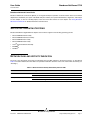
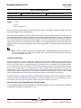
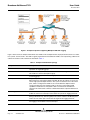
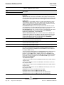
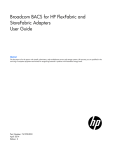
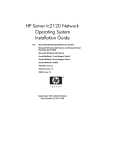
Figure 1: Example of Systems Supporting Multiple VLANs with Tagging
Figure 1 above shows an example network that uses VLANs. In this example network, the physical LAN consists of a switch,
two systems, and five clients. The LAN is logically organized into three different VLANs, each representing a different IP
subnet. The features of this network are described in Table 1:
Table 1: Example VLAN Network Topology
Component
Description
VLAN #1
An IP subnet consisting of the Main System, PC #3, and PC #5. This subnet
represents an engineering group.
VLAN #2
Includes the Main System, PCs #1 and #2 via shared media segment, and PC #5.
This VLAN is a software development group.
VLAN #3
Includes the Main System, the Accounting System and PC #4. This VLAN is an
accounting group.
Main System
A high-use system that needs to be accessed from all VLANs and IP subnets. The
Main System has a Broadcom adapter installed. All three IP subnets are accessed
via the single physical adapter interface. The system is attached to one of the switch
ports, which is configured for VLANs #1, #2, and #3. Both the adapter and the
connected switch port have tagging turned on. Because of the tagging VLAN
capabilities of both devices, the system is able to communicate on all three IP
subnets in this network, but continues to maintain broadcast separation between all
of them.
Accounting System
Available to VLAN #3 only. The Accounting System is isolated from all traffic on
VLANs #1 and #2. The switch port connected to the system has tagging turned off.
PCs #1 and #2
Attached to a shared media hub that is then connected to the switch. PCs #1 and #2
belong to VLAN #2 only, and are logically in the same IP subnet as the Main System
and PC #5. The switch port connected to this segment has tagging turned off.
PC #3
A member of VLAN #1, PC #3 can communicate only with the Main System and PC
#5. Tagging is not enabled on PC #3 switch port.
Bro adco m C orp or atio n
Page 14
VLAN Overview
Document
INGDTM154-CDUM100-R
User Guide
Broadcom NetXtreme 57XX
November 2012
Table 1: Example VLAN Network Topology
Component
Description
PC #4
A member of VLAN #3, PC #4 can only communicate with the systems. Tagging is
not enabled on PC #4 switch port.
PC #5
A member of both VLANs #1 and #2, PC #5 has an Broadcom adapter installed. It is
connected to switch port #10. Both the adapter and the switch port are configured for
VLANs #1 and #2 and have tagging enabled.
Note: VLAN tagging is only required to be enabled on switch ports that create trunk links to other switches, or on
ports connected to tag-capable end-stations, such as systems or workstations with Broadcom adapters.
ADDING VLANS TO TEAMS
Each team supports up to 64 VLANs (63 tagged and 1 untagged). Note that Broadcom adapters can be part of a team with
VLANs. With multiple VLANs on an adapter, a server with a single adapter can have a logical presence on multiple IP
subnets. With multiple VLANs in a team, a system can have a logical presence on multiple IP subnets and benefit from load
balancing and failover. For instructions on adding a VLAN to a team, see Adding VLANs to Teams for Windows operating
systems.
Note: Adapters that are members of a failover team can also be configured to support VLANs.
Bro adco m Co rp or atio n
Document
INGDTM154-CDUM100-R
VLAN Overview
Page 15
Broadcom NetXtreme 57XX
User Guide
November 2012
Bro adco m C orp or atio n
Page 16
VLAN Overview
Document
INGDTM154-CDUM100-R
User Guide
Broadcom NetXtreme 57XX
November 2012
W i ndow s Drive r Softwar e: B roadcom NetLink ® /
Ne tXtr eme ® 5 7X X Use r Gu i de
•
Installing the Driver Software
•
Updating the Driver Software
•
Removing the Driver Software
•
Viewing or Changing the Properties of the Controller
•
Setting Power Management Options
INSTALLING THE DRIVER SOFTWARE
Notes:
•
These instructions are based on the assumption that your Broadcom NetXtreme Gigabit Ethernet Controller
was not factory installed. If your adapter was installed at the factory, the driver software has been installed for
you.
•
For Vista systems, the driver software has been installed for you. To ensure your machine has the latest driver,
see Updating the Driver Software.
When Windows first starts after a hardware device (such as a Broadcom NetXtreme 57XX Gigabit Ethernet Controller) has
been installed, or after the existing device driver has been removed, the operating system automatically detects the
hardware and prompts you to install the driver software for that device.
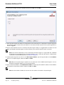
Both a graphical interactive installation mode (see Using the Driver Installer) and a command-line silent mode for unattended
installation (see Using Silent Installation) are available.
Notes:
•
Before installing the driver software, verify that the Windows operating system has been upgraded to the latest
version with the latest service pack applied.
•
A network device driver must be installed before the Broadcom NetXtreme 57XX Gigabit Ethernet Controller
can be used with your Windows operating system. Drivers are located on the installation CD as well as the
Broadcom website at http://www.broadcom.com/support/ethernet_nic/downloaddrivers.php.
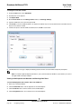
Using the Driver Installer
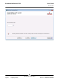
1. When the Found New Hardware Wizard appears, click Cancel.
2. Insert the installation CD into the CD or DVD drive.
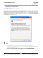
3. On the installation CD, open the folder containing the driver installer program (Setup.exe), and then double-click
Setup.exe to launch the InstallShield® Wizard.
Note: If you have a standard account on a Vista system, you will receive the User Account Control dialog box. Verify
Bro adco m Co rp or atio n
INGDTM154-CDUM100-R
Windows Driver Software: Broadcom NetLink®/NetXtreme® 57XX User Guide
Page 17
Broadcom NetXtreme 57XX
User Guide
November 2012
the presented information and select Continue.
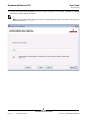
4. Click Next to continue.
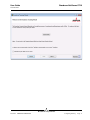
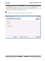
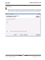
5. After you review the license agreement, click I accept the terms in the license agreement, and then click Next to
continue.
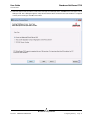
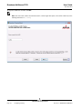
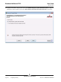
6. Click Install.
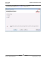
7. Click Finish to close the wizard.
Using Silent Installation
For silent installation, run commands at the command prompt.
Notes:
•
All commands are case sensitive.
•
The Command Prompt must be “Run as Adminstrator” when using “msiexec” for “silent” install/uninstall(s).
•
For more detailed instructions and information about unattended installs, refer to the Silent.txt file in the
Tools\DrvInst\ia32 folder.
To perform a silent install from within the installer source folder
Type the following:
setup /s /v/qn
or
msiexec /i "BDrvInst.msi" /qn
To perform a silent upgrade from within the installer source folder
Type the following:
setup /s /v/qn
To perform a silent uninstall from within the installer source folder
Type the following:
msiexec /x "BDrvInst.msi" /qn
To perform a silent uninstall from any folder
Type the following:
msiexec /x "{B7F54262-AB66-44B3-88BF-9FC69941B643}" /qn
To perform a silent reinstall of the same installer
Type the following:
setup /s /v"/qn REINSTALL=ALL"
To perform a GUI reinstall of the same installer
Bro adco m C orp or atio n
Page 18
Windows Driver Software: Broadcom NetLink®/NetXtreme® 57XX User Guide
Document
INGDTM154-CDUM100-R
User Guide
Broadcom NetXtreme 57XX
November 2012
Type the following:
setup /V"REINSTALL=ALL"
Using the Found New Hardware Wizard
These instructions are based on the assumption that you are using Windows XP Service Pack 2.
1. When the Found New Hardware Wizard opens, click No, not this time, and then click Next.
2. Click Install from a list or specific location (Advanced), and then click Next.
3. Click Include this location in the search, browse to the folder on the installation CD where the drivers for Windows XP
are located, and then click Next.
4. Click Finish to close the wizard.
UPDATING THE DRIVER SOFTWARE
To update the driver software
You must have administrative rights to update the driver software. If you have a standard account on Windows Vista, you
will receive the User Account Control dialog box. Verify the presented information and select Continue.
1. Start Windows and log on.
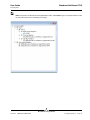
2. In Control Panel, click System to view System Properties.
3. Click the Hardware tab, and then click Device Manager.
4. Right-click the name of the Broadcom NetXtreme 57XX Gigabit Ethernet Controller and click Update Driver.
5. Click Include this location in the search, browse to the folder on the installation CD where the drivers are located, and
then click Next.
6. Click Finish to close the wizard.
REMOVING THE DRIVER SOFTWARE
You must have administrative rights to update the driver software. If you have a standard account on Windows Vista, you
will receive the User Account Control dialog box. Verify the presented information and select Continue.
1. In Control Panel, double-click Add or Remove Programs.
2. Click Broadcom Gigabit Integrated Controller, and then click Remove.
3. Click Yes to remove the drivers.
4. Click OK.
Note: You can also remove the device drivers by running the InstallShield installer again and clicking Remove.
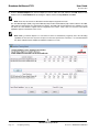
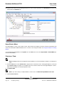
VIEWING OR CHANGING THE PROPERTIES OF THE CONTROLLER
To view or change the properties of the Broadcom NetXtreme 57XX Gigabit Ethernet Controller
1. In Control Panel, click (or double-click) Broadcom Control Suite.
2. Click the Advanced tab.
Bro adco m Co rp or atio n
INGDTM154-CDUM100-R
Windows Driver Software: Broadcom NetLink®/NetXtreme® 57XX User Guide
Page 19
Broadcom NetXtreme 57XX
User Guide
November 2012
3. See Setting Adapter Properties for a detailed description of the available properties as well as for instructions for viewing
and changing the value of a particular property.
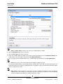
SETTING POWER MANAGEMENT OPTIONS
You can set Power Management options to allow the operating system to turn off the adapter to save power or to allow the
adapter to wake up the system. If the device is busy doing something (servicing a call, for example) however, the operating
system will not shut down the device. The operating system attempts to shut down every possible device only when the
system attempts to go into hibernation. To have the adapter stay on at all times, do not click the Allow the computer to
turn off the device to save power check box.
Notes:
•
The Power Management tab is available only for systems that support power management.
•
To enable Wake on LAN (WOL) when the system is on standby, select the Allow the device to bring the
computer out of standby check box.
•
If you select Only allow management stations to bring the computer out of standby, the system can be
brought out of standby only by Magic Packet, regardless of the settings in Wake Up Capabilities.
Bro adco m C orp or atio n
Page 20
Windows Driver Software: Broadcom NetLink®/NetXtreme® 57XX User Guide
Document
INGDTM154-CDUM100-R
User Guide
Broadcom NetXtreme 57XX
November 2012
NDIS2 Dr iv er Softwar e: Broadcom NetLink ® /
Ne tXtr eme ® 5 7X X Use r Gu i de
•
Preinstallation Requirements
•
Installing the NDIS2 Driver Software for Use on MS-DOS Platforms
•
Configuring the NDIS2 Driver Software
PREINSTALLATION REQUIREMENTS
Before you can successfully install the NDIS2 driver software, the Broadcom NetXtreme Gigabit Ethernet adapter must be
physically installed in the system. Networking software that is appropriate to the operating system (such as Microsoft LAN
Manager 2.2 for MS-DOS) must already be running on your system.
INSTALLING THE NDIS2 DRIVER SOFTWARE FOR USE ON MS-DOS PLATFORMS
The NDIS2 driver software can be run from an MS-DOS startup disk using Microsoft Network Client 3.0 or from the hard disk
using Microsoft LAN Manager 2.2.
Creating a Startup Disk to Run Microsoft Network Client
To perform this installation you must have the following items:
•
Windows NT Server 4.0 CD-ROM
•
A blank MS-DOS system disk (3.5" high-density floppy disk)
•
Access to the Broadcom NDIS2 driver file (B57.dos). This file is located on the installation CD.
Notes:
•
Windows NT Server 4.0 users. When running Setup for Microsoft Network Client v3.0 for MS-DOS, click
any network card from the list (NE2000 Compatible, for example) to create the startup disk.
•
After creating the startup disk, follow the instructions in Modifying the Startup Disk.
To create a startup disk
1. Create a folder called NCADMIN in the root of the C drive.
2. Copy the NCADMIN.CN_, NCADMIN.EX_, and NCADMIN.HL_ files from the I386 folder on the Windows NT Server 4.0
CD-ROM.
3. Open a command prompt window and change the directory to C:\NCADMIN.
4. Type expand -r ncadmin.* and press ENTER.
5. Close the command prompt window by typing exit and then pressing ENTER.
6. Start Windows Explorer.
7. Open the NCADMIN folder and double-click ncadmin.exe.
8. Follow the on-screen instructions to make the network startup disk (choose NE2000 Compatible from the list of
adapters).
Bro adco m Co rp or atio n
Document
INGDTM154-CDUM100-R
NDIS2 Driver Software: Broadcom NetLink®/NetXtreme® 57XX User Guide
Page 21
Broadcom NetXtreme 57XX
User Guide
November 2012
Modifying the Startup Disk
To modify the startup disk
1. Edit A:\Net\Protocol.ini with Notepad or a similar text editor.
a. Change DriverName=$ to DriverName=B57$.
b. Remove all other parameter entries under the [MS$NE2CLONE] or equivalent section such as IOBASE=0x300 or
INTERRUPT=3, and so on.
Example: Protocol.ini file for IP
[network.setup]
version=0x3110
netcard=ms$ne2clone,1,MS$NE2CLONE,1
transport=tcpip,TCPIP
lana0=ms$ne2clone,1,tcpip
[MS$NE2CLONE]
DriverName=B57$
[protman]
DriverName=PROTMAN$
PRIORITY=MS$NDISHLP
[tcpip]
NBSessions=6
DefaultGateway=0
SubNetMask=255 0 0 0
IPAddress=192 168 0 1
DisableDHCP=0
DriverName=TCPIP$
BINDINGS=MS$NE2CLONE
LANABASE=0
Example: Protocol.ini file for IPX
[network.setup]
version=0x3110
netcard=ms$ne2clone,1,MS$NE2CLONE,1
transport=ms$ndishlp,MS$NDISHLP
transport=ms$nwlink,MS$NWLINK
lana0=ms$ne2clone,1,ms$nwlink
lana1=ms$ne2clone,1,ms$ndishlp
[MS$NE2CLONE]
DriverName=B57$
[protman]
DriverName=PROTMAN$
PRIORITY=MS$NDISHLP
[MS$NDISHLP]
DriverName=ndishlp$
BINDINGS=ms$ne2clone
[ms$nwlink]
DriverName=nwlink$
FRAME=Ethernet_802.2
BINDINGS=MS$NE2CLONE
LANABASE=0
Example: Protocol.ini file for NetBEUI
[network.setup]
version=0x3110
netcard=ms$ne2clone,1,MS$NE2CLONE,1
transport=ms$ndishlp,MS$NDISHLP
Bro adco m C orp or atio n
Page 22
NDIS2 Driver Software: Broadcom NetLink®/NetXtreme® 57XX User Guide
Document
INGDTM154-CDUM100-R
User Guide
Broadcom NetXtreme 57XX
November 2012
transport=ms$netbeui,MS$NETBEUI
lana0=ms$ne2clone,1,ms$ndishlp
lana1=ms$ne2clone,1,ms$netbeui
[MS$NE2CLONE]
DriverName=B57$
[protman]
DriverName=PROTMAN$
PRIORITY=MS$NDISHLP
[MS$NDISHLP]
DriverName=ndishlp$
BINDINGS=MS$NE2CLONE
[MS$NETBEUI]
DriverName=netbeui$
SESSIONS=10
NCBS=12
BINDINGS=MS$NE2CLONE
LANABASE=0
2. Edit A:\Net\System.ini.
a. Change netcard= to netcard=b57.dos.
b. Check for references to C:\NET and change C:\NET to A:\NET if necessary.
Example: System.ini file
[network]
sizworkbuf=1498
filesharing=no
printsharing=no
autologon=yes
computername=MYPC
lanroot=A:\NET
username=USER1
workgroup=WORKGROUP
reconnect=yes
dospophotkey=N
lmlogon=0
logondomain=
preferredredir=basic
autostart=basic
maxconnections=8
[network drivers]
netcard=B57.dos
transport=ndishlp.sys,*netbeui
devdir=A:\NET
LoadRMDrivers=yes
3. Copy B57.dos to A:\Net.
4. Create the appropriate Autoexec.bat file in drive A for the chosen protocol as shown below.
For TCP/IP
path=a:\net
a:\net\net initialize
a:\net\netbind.com
a:\net\umb.com
a:\net\tcptsr.exe
a:\net\tinyrfc.exe
a:\net\nmtsr.exe
a:\net\emsbfr.exe
Bro adco m Co rp or atio n
Document
INGDTM154-CDUM100-R
NDIS2 Driver Software: Broadcom NetLink®/NetXtreme® 57XX User Guide
Page 23
Broadcom NetXtreme 57XX
User Guide
November 2012
a:\net\net start basic
net use z: \\SERVERNAME\SHARENAME
For IPX
SET PATH=A:\NET
A:\NET\net initialize
A:\NET\nwlink
A:\NET\NET START BASIC
net use z: \\SERVERNAME\SHARENAME
For NetBEUI
SET PATH=A:\NET
A:\NET\NET START BASIC
net use z: \\SERVERNAME\SHARENAME
5. Create a Config.sys file on the startup disk in drive A as shown below.
files=30
device=a:\net\ifshlp.sys
lastdrive=z
Installing the DOS NDIS2 Driver Software on the Hard Disk
To install the DOS NDIS2 Driver Software on the hard disk
1. Verify that the system has Microsoft LAN Manager 2.2 installed, with a protocol such as NetBEUI configured.
2. Create a folder on your hard disk to store the NDIS 2.01 driver.
Example: C:\LANMAN
3. Copy the B57.dos file to this folder.
4. Edit the Config.sys file by adding the following lines:
DEVICE = C:\LANMAN\PROTMAN.DOS
DEVICE = C:\LANMAN\B57.DOS
DEVICE = C:\LANMAN\NETBEUI.DOS
5. Edit the Autoexec.bat file by adding the following lines:
C:\LANMAN\NETBIND.EXE
C:\LANMAN\NET START WORKSTATION
C:\LANMAN\NET USE drive letter: \\server name\resource name
6. Edit the Protocol.ini file (located in C:\LANMAN) to configure the driver to bind with NetBEUI or any other protocols.
Example:
PROTOCOL MANAGER]
DriverName = PROTMAN$
NETBEUI_XIF]
DriverName = netbeui$
BINDINGS = B57
B57]
DriverName = "B57$"
7. Restart the computer to complete the installation.
Note: The driver loads during system configuration and displays the Broadcom banner, controller name, MAC
address, IRQ number, detected line speed, and the controller BusNum and DevNum. If the driver fails to load, an
initialization fail message is displayed.
Bro adco m C orp or atio n
Page 24
NDIS2 Driver Software: Broadcom NetLink®/NetXtreme® 57XX User Guide
Document
INGDTM154-CDUM100-R
User Guide
Broadcom NetXtreme 57XX
November 2012
CONFIGURING THE NDIS2 DRIVER SOFTWARE
The NDIS2 driver software can be configured by adding specific optional keywords to the Protocol.ini file. If multiple (or
multiport) Broadcom NetXtreme Gigabit Ethernet adapters are installed in a system, the NDIS2 driver software loads by
default on the adapter/port that has a good link. If 2 or more adapters have a good link, the NDIS2 driver software loads on
the adapter having the latest Device ID. If 2 or more adapters that have a good link have the same Device ID, the NDIS2
driver software loads on the adapter that is located in the slot having the lowest bus number.
NOTE: On MS-DOS platforms, it is not recommended to load the NDIS2 driver software on more than 1 adapter; the required
NDIS2 protocol manager that supports multiple binds is not available in the MS-DOS environment.
If it is necessary to have the NDIS2 driver load on certain adapters in a certain order, the BusNum, DevNum, and FuncNum
keywords can be used. Do not use these keywords unless you know how to configure PCI devices.
The BusNum keyword value, which represents the PCI bus number in which the adapter is located, is a decimal number
ranging from 0 to 255.
The FuncNum keyword value, which represents the function (port) number of a multiport adapter, is a decimal number, with
0 representing the first port, and 1 representing the second port.
The DevNum keyword value, which represents the assigned device number, is a decimal number ranging from 0 to 31.
NOTE: At the end of the NDIS2 driver software installation process, note the BusNum and DevNum values that are
displayed. Alternatively, use Broadcom Advanced Control Suite to view the bus number, function (port) number, and device
number assigned to each adapter (Windows users only).
Example BusNum, DevNum, and FuncNum keyword entries for loading the NDIS2 driver on multiple adapters in a certain
order are shown below:
[B57]
DRIVERNAME =
BUSNUM = 3
DEVNUM = 10
[B57_2]
DRIVERNAME =
BUSNUM 3
DEVNUM 11
[B57_3]
DRIVERNAME =
BUSNUM 3
DEVNUM 12
[B57_4]
DRIVERNAME =
BUSNUM 3
DEVNUM 13
B57$
B572$
B573$
B574$
The LineSpeed keyword is used to force the speed of the network connection. The LineSpeed keyword requires a decimal
number and of either 10, 100, or 1000. Technically, a line speed of 1000 Mbit/s cannot be forced and can be achieved only
through auto-negotiation. For the sake of simplicity, the driver performs auto-negotiation when the line speed is set to a value
of 1000. Forced 1000 Mbit/s speed is not needed for copper links; auto-negotiation is the proper supported configuration
under the IEEE Ethernet specification.
Bro adco m Co rp or atio n
Document
INGDTM154-CDUM100-R
NDIS2 Driver Software: Broadcom NetLink®/NetXtreme® 57XX User Guide
Page 25
Broadcom NetXtreme 57XX
User Guide
November 2012
The Duplex keyword is used to force the duplex mode of the adapter. The Duplex keyword requires a text string of either
HALF or FULL. When the Duplex keyword is used, the LineSpeed keyword must also be used. If neither keyword is used,
the network adapter defaults to auto-negotiation mode.
The NodeAddress keyword specifies the network address used by the adapter. If a multicast address or a broadcast address
is specified, the adapter uses the default MAC address.
The FixCheckSumOff keyword turns off the driver workaround for the TCP/IP stack to recognize the ones complement
version of the checksum.
Example entries for the LineSpeed, Duplex, and NodeAddress keywords are shown below:
[B57]
DRIVERNAME = B57$
BUSNUM = 3
DEVNUM = 10
PORTNUM = 0
LINESPEED = 100
DUPLEX = FULL
NODEADDRESS = ì001020304050î
Bro adco m C orp or atio n
Page 26
NDIS2 Driver Software: Broadcom NetLink®/NetXtreme® 57XX User Guide
Document
INGDTM154-CDUM100-R
User Guide
Broadcom NetXtreme 57XX
November 2012
O D I D r i v e r S o f t w a r e : B roa dc om N e t Li n k ® /
Ne tXtr eme ® 5 7X X Use r Gu i de
•
Installing the Driver Software
•
Configuring the Driver Software
The Open Data-Link Interface (ODI) driver software allows LAN drivers to work together irrespective of differences between
the hardware and/or the protocol stacks of communicating computers. An intervening layer, called the link support layer
(LSL), is responsible for routing different packet types between LAN drivers and protocol stacks.
INSTALLING THE DRIVER SOFTWARE
Installing the ODI driver software involves the following steps:
1. Verifying that the MS-DOS operating system files are installed on your system hard disk or are available on a removable
storage device.
2. Installing the ODI driver software in the MS-DOS environment.
3. If necessary, reconfiguring the driver software after installation.
Preinstallation Requirements
Verify that the Broadcom NetXtreme Gigabit Ethernet adapter driver software has been installed on your system. If it has
not, install it (see Installing the Driver Software). Otherwise, you cannot use a Broadcom NetXtreme Gigabit Ethernet adapter
in the MS-DOS environment.
Note: To successfully install the adapter driver for MS-DOS, the adapter must be installed before you install the
adapter driver.
Installing the Novell NetWare Client32 Driver for MS-DOS
1. Extract the dw271.zip file to a temporary directory on the hard disk.
2. Double-click the dw271e.exe file.
3. Type y and then press ENTER when you are prompted for a response.
4. Restart your system in MS-DOS mode.
5. Change to the directory where the extracted files are located.
6. Type install, and then press ENTER.
7. Read the agreement, and then press ENTER to accept the agreement.
8. Using the UP ARROW or DOWN ARROW key as necessary, highlight Novell Client for DOS (required), and then press
F10 to save and continue.
9. Highlight 32-bit LAN Drivers, and then press F10 to save and continue.
10. Insert the floppy disk containing the Broadcom 32-bit LAN driver files into the floppy disk drive.
11. Highlight USER SPECIFIED 32-BIT DRIVER, and then press ENTER.
12. Press ENTER.
Bro adco m Co rp or atio n
Document
INGDTM154-CDUM100-R
ODI Driver Software: Broadcom NetLink®/NetXtreme® 57XX User Guide
Page 27
Broadcom NetXtreme 57XX
User Guide
November 2012
13. Highlight NetXtreme Gigabit Ethernet Driver, and then press ENTER.
14. Press ENTER.
15. Select Receive Buffers, type 32 for the value, and then press F10 to save and continue.
Note: Do not change the default settings for any of the other items in the Installation Configuration Summary.
16. Press F10 to save and continue. The B57.LAN and B57.ldi files are copied to the directory.
17. Restart the system to complete the install.
18. As the files are being loaded, the system attempts to attach to a Netware system using the frame types specified in
Net.cfg. If the connection is successful, a dialog box is displayed. Change to drive F and log on to the NetWare system.
Note: The driver loads during system configuration, and the Broadcom banner, the adapter name, the MAC
address, the IRQ number, the detected line speed, and the bus number (BusNum) and device number (DevNum)
of the adapter are displayed. If the driver fails to load, an initialization fail message appears.
Installing the Novell NetWare ODI Client16 Driver for MS-DOS
1. Extract each of the 6 vlm121_*.exe files to a temporary common directory on the hard disk.
2. Type y and then press ENTER each time you are prompted for a response.
3. Restart your system in MS-DOS mode.
4. Change to the directory where the extracted files are located.
5. Type install, and then press ENTER.
6. Using the UP ARROW or DOWN ARROW key as necessary, highlight Highlight here and press <Enter> to see the list
below item 5, and then press ENTER.
7. Do not change the default settings for items 1 through 4. Insert the floppy disk containing the Broadcom ODI 16-bit driver
files into the floppy disk drive.
8. Highlight Other Drivers, and then press ENTER.
9. Press ENTER.
10. Highlight Broadcom Ethernet DOS ODI, and then press ENTER.
11. Highlight Frame Type, and then press ENTER.
12. Highlight Ethernet 802.2, and then press ENTER.
13. Press F10 to save and continue.
14. Highlight Highlight here and press <Enter> to install, and then press ENTER.
15. The B57.com and B57.ins files are copied to the directory.
16. Restart the system to complete the install.
17. As the files are being loaded, the system attempts to attach to a Netware system using the frame types specified in
Net.cfg. If the connection is successful, a dialog box is displayed.
18. Change to drive F and log on to the NetWare system.
Note: The driver loads during system configuration, and the Broadcom banner, the adapter name, the MAC
address, the IRQ number, the detected line speed, and the bus number (BusNum) and device number (DevNum)
assigned to the adapter are displayed. If the driver fails to load, an initialization fail message is displayed.
Bro adco m C orp or atio n
Page 28
ODI Driver Software: Broadcom NetLink®/NetXtreme® 57XX User Guide
Document
INGDTM154-CDUM100-R
User Guide
Broadcom NetXtreme 57XX
November 2012
CONFIGURING THE DRIVER SOFTWARE
The ODI driver software can be configured by adding specific optional keywords to the Net.cfg file.
If multiple (or multiport) Broadcom NetXtreme Gigabit Ethernet adapters are installed in a system, the ODI driver software
loads by default on the adapter/port that has a good link. If 2 or more adapters have a good link, the ODI driver software
loads on the adapter having the latest Device ID. If 2 or more adapters that have a good link have the same Device ID, the
ODI driver software loads on the adapter that is located in the slot having the lowest bus number. If it is necessary to have
the ODI driver load on certain adapters in a certain order, the BusNum, DevNum, and FuncNum keywords can be used.
Do not use these keywords unless you know how to configure PCI devices.
The BusNum keyword value, which represents the PCI bus number in which the adapter is located, is a hexadecimal
number ranging from 0 to 255.
The FuncNum keyword value, which represents the function (port) number of a multiport adapter, is a hexadecimal number
with 0 representing the first port and 1 representing the second port.
The DevNum keyword value, which represents the assigned device number, is a hexadecimal number ranging from 0 to 31.
Notes:
•
At the end of the ODI driver software installation process, note the BusNum and DevNum values that are
displayed. Alternatively, use Broadcom Advanced Control Suite to view the bus number, function (port) number,
and device number assigned to each adapter (Windows users only).
•
The values for the BusNum, DevNum, and FuncNum keywords are displayed in hexadecimal notation when the
driver loads on the adapter.
For example, BusNum, DevNum, and FuncNum keyword entries for loading the ODI driver on multiple adapters in a
certain order are shown below:
PROTOCOL <protocol name>
BIND B57
BIND B57
LINK DRIVER B57
BUSNUM 1
DEVNUM 9
FRAME <frame #1 name>
LINK DRIVER B57
BUSNUM 1
DEVNUM A
FRAME <frame #2 name>
The LineSpeed keyword is used to force the speed of the network connection. The LineSpeed keyword requires a decimal
number and of either 10, 100, or 1000. Technically, a line speed of 1000 Mbit/s cannot be forced and can be achieved only
through auto-negotiation. For the sake of simplicity, the driver performs auto-negotiation when the line speed is set to a value
of 1000. Forced 1000 Mbit/s speed is not needed for copper links; auto-negotiation is the proper supported configuration
under the IEEE Ethernet specification.
The Duplex keyword is used to force the duplex mode of the adapter. The Duplex keyword requires a text string of either
HALF or FULL. When the Duplex keyword is used, the LineSpeed keyword must also be used. If neither keyword is used,
the network adapter defaults to auto-negotiation mode.
Example keyword entries for the LineSpeed, and Duplex keywords are shown below:
Bro adco m Co rp or atio n
Document
INGDTM154-CDUM100-R
ODI Driver Software: Broadcom NetLink®/NetXtreme® 57XX User Guide
Page 29
Broadcom NetXtreme 57XX
User Guide
November 2012
LINK DRIVER B57
LINESPEED 100
DUPLEX FULL
Bro adco m C orp or atio n
Page 30
ODI Driver Software: Broadcom NetLink®/NetXtreme® 57XX User Guide
Document
INGDTM154-CDUM100-R
User Guide
Broadcom NetXtreme 57XX
November 2012
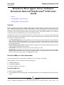
B ro adc om B oo t A g en t D ri ver S o f t wa re:
Broadcom NetLink ® /NetXtre me ® 5 7X X Use r
G ui de
•
Overview
•
Setting Up MBA in a Client Environment
•
Setting Up MBA in a System Environment
OVERVIEW
Broadcom NetXtreme Gigabit Ethernet adapters support Preboot Execution Environment (PXE), Remote Program Load
(RPL), and Bootstrap Protocol (BootP). Multi-Boot Agent (MBA) is a software module that allows your networked system to
boot with the images provided by remote systems across the network. The Broadcom MBA driver complies with the PXE 2.1
specification and is released with both monolithic and split binary images. This provides flexibility to users in different
environments where the motherboard may or may not have built-in base code.
The MBA module operates in a client/system environment. A network consists of one or more boot systems that provide
boot images to multiple systems through the network. The Broadcom implementation of the MBA module has been tested
successfully in the following environments:
Linux® Red Hat® PXE Server. Broadcom PXE clients are able to remotely boot and use network resources (NFS mount,
and so forth) and to perform Linux installations. In the case of a remote boot, the Linux universal driver binds seamlessly
with the Broadcom Universal Network Driver Interface (UNDI) and provides a network interface in the Linux remotelybooted client environment.
Microsoft® Windows Server 2003. Using Windows Remote Installation Services (RIS), Broadcom PXE clients are able
to perform remote installations from the network.
Intel® APITEST. The Broadcom PXE driver passes all API compliance test suites.
MS-DOS UNDI. The MS-DOS Universal Network Driver Interface (UNDI) seamlessly binds with the Broadcom UNDI to
provide a network device driver interface specification (NDIS2) interface to the upper layer protocol stack. This allows
systems to connect to network resources in an MS-DOS environment.
SETTING UP MBA IN A CLIENT ENVIRONMENT
Use the following procedure for add-in NICs. For LOMs, refer to your computer’s system guide.
Setting up MBA in a client environment involves the following steps:
1. Enabling the MBA driver.
2. Configuring the MBA driver.
3. Setting up the BIOS for the boot order.
Enabling the MBA Driver
To enable or disable the MBA driver:
1. Insert an MS-DOS 6.22 bootable floppy disk containing the B57udiag.exe file in the floppy disk drive and power up your
system.
Bro adco m Co rp or atio n
Document
INGDTM154-CDUM100-RBroadcom Boot Agent Driver Software: Broadcom NetLink®/NetXtreme® 57XX User Guide
Page
Broadcom NetXtreme 57XX
User Guide
November 2012
2. Type:
drive:\dos\utility
where
drive is the drive letter of the CD-ROM drive.
3. Type:
b57udiag -mba [ 0-disable | 1-enable ] -c devnum
where
devnum is the specific device(s) number (0,1,2,…) to be programmed.
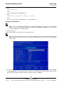
Configuring the MBA Driver
Note: You can use the MBA Configuration Menu to configure the MBA driver one adapter at a time as described
below, or you can use the Broadcom NetXtreme User Diagnostics MS-DOS based application to simultaneously
configure the MBA driver for multiple adapters.
1. Restart your system.
2. Press CTRL+S within 4 seconds after you are prompted to do so.
Note: The message prompting you to press CTRL+S is displayed once for each Broadcom NetXtreme Gigabit
Ethernet adapter you have in your system. The messages are displayed in the same order as the assigned adapter
device number.
3. Use the UP ARROW and DOWN ARROW keys to move to the Boot Protocol menu item. Then use the RIGHT ARROW
or LEFT ARROW key to select the boot protocol of choice. The available boot protocols include Preboot Execution
Environment (PXE), Remote Program Load (RPL), and Bootstrap Protocol (BOOTP).
Bro adco m C orp or atio n
Page 32
Broadcom Boot Agent Driver Software: Broadcom NetLink®/NetXtreme® 57XX User Guide
Document
INGDTM154-
User Guide
Broadcom NetXtreme 57XX
November 2012
Note: If you have multiple adapters in your system and you are unsure which adapter you are configuring, press
CTRL+F6, which causes the port LEDs on the adapter to start blinking.
4. Use the UP ARROW, DOWN ARROW, LEFT ARROW, and RIGHT ARROW keys to move to and change the values for
other menu items, as desired.
5. Press F4 to save your settings.
6. Press ESC when you are finished.
Setting Up the BIOS
To boot from the network with the MBA, make the MBA enabled adapter the first bootable device under the BIOS. This
procedure depends on the system BIOS implementation. Refer to the user manual for the system for instructions.
SETTING UP MBA IN A SYSTEM ENVIRONMENT
Linux Red Hat PXE Server
The Red Hat Linux 8.0 (or later) distribution has PXE Server support. It allows users to remotely perform a complete Linux
installation over the network. The distribution comes with the boot images boot kernel (vmlinuz) and initial ram disk (initrd),
which are located on the Red Hat disk#1:
/images/pxeboot/vmlinuz
/images/pxeboot/initrd.img
Refer to the Red Hat documentation for instructions on how to install PXE Server on Linux.
The Initrd.img file distributed with Red Hat 8.0, however, does not have a Linux network driver for the Broadcom NetXtreme
Gigabit Ethernet adapter.
This version requires drivers that are not part of the standard distribution. You can create a driver disk for the Broadcom
NetXtreme Gigabit Ethernet adapter using files obtained from the support website. You can create a driver disk for the
Broadcom NetXtreme 57XX Gigabit Ethernet Controller from the image distributed with the installation CD. Refer to the Linux
Readme.txt file for more information.
A remote boot does not require a standard Linux network driver for the Broadcom NetXtreme Gigabit Ethernet adapter. After
the PXE client downloads the Linux kernel and initial ram disk, the Linux universal driver that came with the Linux distribution
binds with the UNDI code of the PXE to form a Linux network driver.
Note: Refer to the Distrib.txt file on the installation CD for a list of the specific Linux distributions on which the driver
has been tested.
Windows Server 2003/Windows XP
The current version of Windows Server 2003/Windows XP does not include the latest released network driver for the
Broadcom NetXtreme Gigabit Ethernet adapter. You can create a driver disk for the adapter using files obtained from the
support website. To perform remote installations with PXE, include a network driver for the NetXtreme Gigabit Ethernet
adapter as a part of the client installation image on the server. Refer to Microsoft Knowledge Base Article, "How to Add ThirdParty OEM Network Adapters to RIS Installations." See also Troubleshooting for details.
Bro adco m Co rp or atio n
Document
INGDTM154-CDUM100-RBroadcom Boot Agent Driver Software: Broadcom NetLink®/NetXtreme® 57XX User Guide
Page
Broadcom NetXtreme 57XX
User Guide
November 2012
DOS UNDI/Intel APITEST
To boot in DOS mode and connect to a network for the DOS environment, download the Intel PXE PDK from the Intel
website. This PXE PDK comes with a TFTP/ProxyDHCP/Boot server. The PXE PDK can be downloaded from Intel at http:/
/downloadcenter.intel.com/detail_desc.aspx?agr=Y&DwnldID=6100&ProductID=412.
Bro adco m C orp or atio n
Page 34
Broadcom Boot Agent Driver Software: Broadcom NetLink®/NetXtreme® 57XX User Guide
Document
INGDTM154-
User Guide
Broadcom NetXtreme 57XX
November 2012
L inu x D r iv e r S o f tw a r e : B ro a d c o m N e t L i nk ® /
N e t X t r e m e ® 5 7XX User Guide
•
Limitations
•
Packaging
•
Installing TG3 Driver Software
•
Network Installations
•
Patching PCI Files (Optional)
•
Unloading/Removing the TG3 Driver
•
Driver Messages
LIMITATIONS
The current version of the adapter driver has been tested on the latest Red Hat, SuSE, and other Linux distributions for i386,
ia64, and x86_64 CPU architectures using 2.4.x and 2.6.x kernels. The driver has been tested up to kernel version 2.4.33
and 2.6.13. The driver should work on other little endian or big endian CPU architectures, but only very limited testing has
been done on some of these machines. The Makefile may have to be modified to include architecture-specific compile
switches, and some minor changes in the source files may also be required. On these machines, patching the driver into the
kernel is recommended.
PACKAGING
The Linux TG3 driver is released in the following packaging formats (file names):
•
Source RPM (tg3-version.src.rpm)
•
Supplemental (tg3_sup-version.tar.gz)
•
Compressed tar (tg3-version.tar.gz)
Identical source files to build the driver are included in both RPM and TAR source packages. The tar file contains additional
utilities such as patches and driver disk images for network installation.
INSTALLING TG3 DRIVER SOFTWARE
•
Installing the Source RPM Package
Bro adco m Co rp or atio n
Document
INGDTM154-CDUM100-R
Linux Driver Software: Broadcom NetLink®/NetXtreme® 57XX User Guide
Page 35
Broadcom NetXtreme 57XX
User Guide
November 2012
•
Building the Driver from the Source TAR File
INSTALLING THE SOURCE RPM PACKAGE
1. Install the source RPM package.
rpm -ivh tg3-version.src.rpm
2. Change the directory to the RPM path and build the binary driver for your kernel (the RPM path is different for different
Linux distributions).
cd /usr/src/redhat,OpenLinux,turbo,packages,rpm …
rpm -bb SPECS/tg3.spec or rpmbuild -bb SPECS/tg3.spec
rpmbuild -bb SPECS/tg3.spec (for RPM version 4.x.x)
NOTE: During your attempt to install a source RPM package, the following message may be displayed:
error: cannot create %sourcedir /usr/src/redhat/SOURCE
The most likely cause of the error is that the rpm-build package has not been installed. Locate the rpm-build package on
the Linux installation media and install it using the following command:
rpm -ivh rpm-build-version.i386.rpm
Complete the installation of the source RPM.
3. Install the newly-built package (driver and man page).
rpm -ivh RPMS/i386/tg3-version.i386.rpm
Depending on the kernel, the driver is installed to one of the following paths:
2.4.x kernels:
/lib/modules/kernel_version/kernel/drivers/net/tg3.o
2.4.x kernels with the tg3 driver patched in:
/lib/modules/kernel_version/kernel/drivers/addon/tg3/tg3.o
2.6.x kernels:
/lib/modules/kernel_version/kernel/drivers/net/tg3.ko
4. Load the driver.
modprobe tg3
To configure the network protocol and address, refer to the Linux version-specific documentation.
BUILDING THE DRIVER FROM THE SOURCE TAR FILE
1. Create a directory (tg3-version) and extract the TAR files to the directory.
tar xvzf tg3-version.tgz
2. Build the driver tg3.o as a loadable module for the running kernel.
CD tg3-version
make clean
make; make install
3. Test the driver by loading it.
rmmod tg3
modprobe tg3
No message should be returned if this command runs properly.
Bro adco m C orp or atio n
Page 36
Installing TG3 Driver Software
Document
INGDTM154-CDUM100-R
User Guide
Broadcom NetXtreme 57XX
November 2012
NOTE: See the RPM instructions above for the location of the installed driver.
4. To configure network protocol and address, refer to the manuals supplied with your operating system.
NETWORK INSTALLATIONS
For network installations through NFS, FTP, or HTTP (using a network boot disk or PXE), a driver disk that contains the tg3
driver may be needed. The driver disk images for the most recent Red Hat versions are included. Boot drivers for other Linux
versions can be compiled by modifying the Makefile and the make environment. Further information is available from the
Red Hat website, http://www.redhat.com.
To create the driver disk, select the appropriate image file (located in tg3_sup-version.tar.gz) and type the following:
dd if=<version>.dd.img of=/dev/fd0
PATCHING PCI FILES (OPTIONAL)
For hardware detection utilities such as Red Hat kudzu to properly identify tg3 supported devices, a number of files
containing PCI vendor and device information may need to be updated.
Apply the updates by running the scripts provided in the Supplemental tar file. For example, on Red Hat Enterprise Linux,
apply the updates by doing the following:
./patch_pcitbl.sh
/usr/share/hwdata/pcitable pci.updates /usr/share/hwdata/pcitable.new
./patch_pciids.sh /usr/share/hwdata/pci.ids pci.updates /usr/share/hwdata/pci.ids.new
Next, the old files can be backed up and the new files can be renamed for use.
cp /usr/share/hwdata/pci.ids /usr/share/hwdata/old.pci.ids
cp /usr/share/hwdata/pci.ids.new /usr/share/hwdata/pci.ids
cp /usr/share/hwdata/pcitable /usr/share/hwdata/old.pcitable
cp /usr/share/hwdata/pcitable.new /usr/share/hwdata/pcitable
NOTE: The paths above are for Red Hat distributions. These paths may be different on other distributions.
UNLOADING/REMOVING THE TG3 DRIVER
•
Unloading/Removing the Driver from an RPM Installation
•
Removing the Driver from a TAR Installation
Bro adco m Co rp or atio n
Document
INGDTM154-CDUM100-R
Network Installations
Page 37
Broadcom NetXtreme 57XX
User Guide
November 2012
UNLOADING/REMOVING THE DRIVER FROM AN RPM INSTALLATION
To unload the driver, use ifconfig to bring down all ethX interfaces opened by the driver, and then type the following:
rmmod tg3
If the driver was installed using rpm, do the following to remove it:
rpm -e tg3-<version>
REMOVING THE DRIVER FROM A TAR INSTALLATION
If the driver was installed using make install from the tar file, the tg3.o driver file has to be manually deleted from the operating
system. See Installing the Source RPM Package for the location of the installed driver.
If there is an interface configuration that is related to the tg3 driver, then bring the interface down first by using ifconfig ethx
down and then rmod tg3.
DRIVER MESSAGES
The following are the most common sample messages that may be logged in the /var/log/messages file. Use dmesg -nlevel
to control the level at which messages appear on the console. Most systems are set to level 6 by default.
Driver Signon
tg3.c:version (date)
NIC Detected
eth#: Tigon3 [partno (BCM95xxx) rev 4202 PHY (57xx) (PCI Express) 10/100/1000BaseT
Ethernet :00:xx:xx:xx:xx:xx
eth#: RXcsums [1] LinkChg REG [0] MIirq [0] ASF [0] Split [0] Wirespeed [1]TSOcap [1]
eth#: dma_rwctrl [76180000]
ACPI : PCI interrupt 0000:02:02.0 [A] -> GSI 26 (level,low) -> IRQ 233
Flow Control
tg3: eth#: Flow control is configured for TX and for RX.
Link Up and Speed Indication
tg3: eth#: Link is up at 1000 Mbps, full duplex.
Link Down Indication
tg3: eth#: Link is down.
Bro adco m C orp or atio n
Page 38
Driver Messages
Document
INGDTM154-CDUM100-R
User Guide
Broadcom NetXtreme 57XX
November 2012
I ns t a l li n g M a n ag e m e n t A pp li c a t io n s : B roa dc om
Ne tLink ® / N e tX t r e m e ® 5 7X X Use r Gu i de
•
Installing Broadcom Advanced Control Suite and Related Management Applications
•
Updating Broadcom Advanced Control Suite
•
Removing Broadcom Advanced Control Suite
INSTALLING BROADCOM ADVANCED CONTROL SUITE AND RELATED
MANAGEMENT APPLICATIONS
The Broadcom Advanced Control Suite (BACS) software and related management applications can be installed from the
installation CD. Both a graphical interactive installation mode (see Using the Installer) and a command-line silent mode for
unattended installation (see Using Silent Installation) are available.
If available, the following are installed when running the installer:
•
Control Suite. Broadcom Advanced Control Suite (BACS).
•
OOB Mgmt Config. Installs OOB Management Configuration.
•
BASP. Installs Broadcom Advanced Server Program.
•
SNMP. Installs the Simple Network Management Protocol subagent.
•
CIM Provider. Installs the Common Information Model provider.
•
Management Agent. Installs Management Agent for remote monitoring.
Notes:
•
Do not install the BACS software until after you have installed the Broadcom NetXtreme Gigabit Ethernet
adapter(s).
•
Before you begin the installation, close all applications, windows, or dialog boxes.
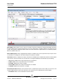
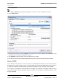
USING THE INSTALLER
To install the management applications
1. Insert the installation CD into the CD or DVD drive.
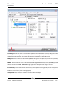
2. Open the folder on the installation CD that contains the BACS Setup.exe file and then double-click Setup.exe to open
the InstallShield Wizard.
Note: If you have a standard account on a Vista system, you will receive the User Account Control dialog box. Verify
the presented information and select Continue.
3. Click Next to continue.
4. After you review the license agreement, click I accept the terms in the license agreement and then click Next to
Bro adco m Co rp or atio n
Document
INGDTM154-CDUM100-RInstalling Management Applications: Broadcom NetLink®/NetXtreme® 57XX User Guide Page 39
Broadcom NetXtreme 57XX
User Guide
November 2012
continue.
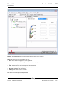
5. Select the features you want installed.
Note: Microsoft SNMP Service must be running for the SNMP subagent to function properly.
6. Click Next.
7. Click Install.
8. Click Finish to close the wizard.
USING SILENT INSTALLATION
To perform a silent installation, see Silent.txt on the installation CD in the BACS directory for your operating system.
UPDATING BROADCOM ADVANCED CONTROL SUITE
Note: Before you begin the update, close all applications, windows, or dialog boxes.
Follow the instructions for Installing Broadcom Advanced Control Suite and Related Management Applications.
REMOVING BROADCOM ADVANCED CONTROL SUITE
1. In Control Panel, click Add or Remove Programs.
2. Click Broadcom Advanced Control Suite and click Change/Remove.
3. In InstallShield Wizard, click Remove, and then click Next.
Note: If you have a standard account on a Vista system, you will receive the User Account Control dialog box. Verify
the presented information and select Continue.
4. Click OK to remove the application and all of its features.
5. Click OK.
6. Restart your computer.
Bro adco m C orp or atio n
Page 40
Updating Broadcom Advanced Control Suite
Document
INGDTM154-CDUM100-R
User Guide
Broadcom NetXtreme 57XX
November 2012
Us in g Broa dc om A dva nc ed Co n t rol Sui t e 4:
Broadcom NetLink ® /NetXtre me ® 5 7X X Use r
G ui de
•
Broadcom Advanced Control Suite Overview
•
Starting Broadcom Advanced Control Suite
•
Using Broadcom Advanced Control Suite
•
Configuring Teaming
BROADCOM ADVANCED CONTROL SUITE OVERVIEW
Broadcom Advanced Control Suite (BACS) is an integrated utility that provides useful information about each network
adapter that is installed in your system. BACS also enables you to perform detailed tests, diagnostics, and analyses on each
adapter, as well as to view and modify property values and view traffic statistics for each adapter.
Broadcom Advanced Server Program (BASP), which runs within Broadcom Advanced Control Suite, is used to configure
teams for load balancing, fault tolerance, and virtual local area networks (VLANs). BASP functionality is available only on
systems that use at least one Broadcom network adapter.
Bro adco m Co rp or atio n
Document
INGDTM154-CDUM100-RUsing Broadcom Advanced Control Suite 4: Broadcom NetLink®/NetXtreme® 57XX User Guide
Broadcom NetXtreme 57XX
User Guide
November 2012
STARTING BROADCOM ADVANCED CONTROL SUITE
In Control Panel, click Broadcom Control Suite 4, or click the BACS icon in the taskbar located at the bottom of the
Windows desktop.
USING BROADCOM ADVANCED CONTROL SUITE
Start BACS. Click the tab that provides the information of interest or from which to perform a desired test, diagnostic,
analysis, or set adapter properties. To create a team, see Configuring Teaming.
BACS INTERFACE
The BACS interface is comprised of the following regions:
•
Explorer View pane
•
Context View selector
•
Context View pane
•
Menu bar
•
Description pane
By default, the Explorer View pane is docked and pinned on the left side of the main window, the Context View pane on the
right, the Context View selector below the menu bar, and the Description pane below the Context View pane. Drag the splitter
between any two panes to vary the size of the panes.
Bro adco m C orp or atio n
Page 42
Starting Broadcom Advanced Control Suite
Document
INGDTM154-CDUM100-R
User Guide
Broadcom NetXtreme 57XX
November 2012
Bro adco m Co rp or atio n
Document
INGDTM154-CDUM100-R
BACS Interface
Page 43
Broadcom NetXtreme 57XX
User Guide
November 2012
EXPLORER VIEW PANE
You can dock and pin the Explorer View pane on the left side, right side, top, or bottom of the main window.
The Explorer View pane lists the objects that can be viewed, analyzed, tested, or configured by BACS. When an item is
selected in the Explorer View pane, the tabs showing the information and options that are available for the item appear in
the Context View pane.
The organization of this panel is designed to present the manageable objects in the same hierarchical manner as drivers
and its subcomponents. This simplifies the management of various elements of the network interface controller (NIC). The
top level of the hierarchy is the Host container, which lists all hosts managed by BACS. Below the hosts are the installed
network adapters, with the manageable elements, such as physical port, VBD, and NDIS below the adapters.
The icon next to each device in the Explorer View pane shows its status. An icon next to a device name that appears normal
means the device is connected and working.
•
X. A red “X” that appears on the device’s icon indicates the device is currently not connected to the network.
•
Greyed out. A device icon that appears greyed out indicates the device is currently disabled.
CONTEXT VIEW SELECTOR
The Context View selector appears below the menu bar and includes the filter and tab categories. Although you can expand
and collapse the categories that appear on tabs in the Context View pane, you can alternatively display a category by
selecting the box next to the category name.
Filter View
In a multiple-host environment using several network adapters, there can be a large number of manageable elements per
adapter that can be difficult and cumbersome to view, configure, and manage all elements. Use the filter to select a particular
device function. Possible filter views include:
•
All
•
Team view
•
NDIS view
•
iSCSI view
•
FCoE view
•
iSCSI Target view
•
FCoE Target view
CONTEXT VIEW PANE
The Context View pane displays all the parameters that you can view for the object selected in the Explorer View pane. The
parameters are grouped by tabs and categories, depending on the parameter type. The available tabs are Information,
Configuration, Diagnostics, and Statistics. Because the BACS interface is context-sensitive, only the parameters that apply
to the selected object can be viewed or configured in the Context View pane.
Bro adco m C orp or atio n
Page 44
BACS Interface
Document
INGDTM154-CDUM100-R
User Guide
Broadcom NetXtreme 57XX
November 2012
MENU BAR
The following appear on the menu bar, but because the menu items are context-sensitive, not all items will be available at
all times:
File menu
•
Team Save As: saves the current team configurations to a file
•
Team Restore: restores any saved team configuration from a file
Action menu
•
Remove Host: removes the selected host
•
Refresh Host: refreshes the information for the selected host
View menu
•
Explorer View: displays/hides the Explorer View pane
•
Tool Bar: displays/hides the tool bar
•
Status Bar: displays/hides the status bar
•
Broadcom Logo: displays/hides the Broadcom Logo on BACS to optimize the maximum viewable space
Tools menu
•
Options: used for configuring BACS preferences
Teams
•
Create Teams: creates new teams with either the Teaming Wizard or in Advanced mode
•
Manage Teams: manages existing teams with either the Teaming Wizard or in Advanced mode
DESCRIPTION PANE
The Description pane provides information, configuration instructions, and options for the selected parameter in the Context
View pane.
Bro adco m Co rp or atio n
Document
INGDTM154-CDUM100-R
BACS Interface
Page 45
Broadcom NetXtreme 57XX
User Guide
November 2012
CONFIGURING PREFERENCES
To enable or disable the BACS tray icon
BACS places an icon in the Windows taskbar when the program is installed. Use the Options window to turn this icon on or
off.
1. From the Tools menu, select Options.
2. Select or clear Enable BACSTray (the option is enabled by default).
3. Click OK.
Setting the teaming mode
1. From the Tools menu, select Options.
2. Select Expert Mode if you do not need the assistance of the teaming wizard to create teams; otherwise, select Wizard
Mode.
3. Click OK.
Setting the Explorer View refresh time
1. From the Tools menu, select Options.
2. Select Auto to set the Explorer View refresh time to 5 seconds. Otherwise, select Custom and select a time, in seconds.
3. Click OK.
Bro adco m C orp or atio n
Page 46
Configuring Preferences
Document
INGDTM154-CDUM100-R
User Guide
Broadcom NetXtreme 57XX
November 2012
CONNECTING TO A HOST
You can add one or more Windows or Linux hosts to manage from BACS.
To add a local host
1. From the Action menu, click Add Host.
2. For both Windows and Linux hosts, do not change the default settings. The User name and Password are not required
while connecting to the local host.
3. Select Persist if you want BACS to save the information for this host.
4. Click Ok. BACS can now be used to view information and manage the host.
To add a remote host
1. From the Action menu, click Add Host.
2. Type the remote host’s name or IP address in the Host box.
3. Select the protocol from the Protocol list. The protocol options for Windows are WMI, WinRM, or Try All. The protocol
options for Linux are CimXML, WinRM, or Try All. The Try All option forces the GUI client to try all options.
4. Select the HTTP scheme, or the HTTPS scheme for added security.
5. Type the Port Number value you used to configure the host, if it is different than the default value of 5985.
6. Type the User name and Password.
7. Select Persist if you want BACS to save the information for this host. The host will appear in the Explorer Pane whenever
you reopen BACS, and you will not need to enter the host IP address or host name when connecting to the host. For
security reasons, you must enter the User name and Password every time.
8. Click OK.
Bro adco m Co rp or atio n
Document
INGDTM154-CDUM100-R
Connecting to a Host
Page 47
Broadcom NetXtreme 57XX
User Guide
November 2012
MANAGING THE HOST
At the host level, you can view host information and configure parameters from the following tabs:
•
Information
•
Configuration
To view host information
Select the host in the Explorer View pane, and then select the Information tab to view host-level information.
Information Tab: Host Information
Host Name. Displays the name of the host.
OS Version Info. Displays the operating system, including the version.
Platform. Displays the hardware architecture platform (for example, 32-bit or 64-bit)
To configure the host
Select the host in the Explorer View pane, and then select the Configuration tab to configure host-level parameters.
Bro adco m C orp or atio n
Page 48
Managing the Host
Document
INGDTM154-CDUM100-R
User Guide
Broadcom NetXtreme 57XX
November 2012
Configuration Tab: System Management
Chimney Offload State. Enable or disable chimney offload at the host level, rather than at the device level, and then click
Apply.
MANAGING THE NETWORK ADAPTER
The installed network adapters appear one level below the host in the hierarchical tree in the Explorer View pane. At the
adapter level, you can view information and configure parameters from the following tabs:
•
Information
•
Configuration
VIEWING ADAPTER INFORMATION
The Vital Signs section of the Information tab has useful information about the network adapters that are installed in your
system, such as the link status of the adapter and general network connectivity.
Select the network adapter in the Explorer View pane, and then select the Information tab to view adapter-level
information.
Bro adco m Co rp or atio n
Document
INGDTM154-CDUM100-R
Managing the Network Adapter
Page 49
Broadcom NetXtreme 57XX
User Guide
November 2012
NOTES:
•
Information about Broadcom network adapters may be more comprehensive than information about network
adapters made by others.
•
Some information may not be available for all Broadcom network adapters.
MAC Address. A physical MAC (media access control) address that is assigned to the adapter by the manufacturer. The
physical address is never all 0s.
Permanent MAC Address. The unique hardware address assigned to the network adapter.
IP Address. The network address associated with the adapter. If the IP address is all 0s, the associated driver has not been
bound with Internet Protocol (IP).
Link Status. The status of the network link.
•
Up. A link is established.
•
Down. A link is not established.
Duplex. The adapter is operating in the indicated duplex mode.
Speed (in Mbps). The link speed of the adapter, in megabits per second.
Bro adco m C orp or atio n
Page 50
Managing the Network Adapter
Document
INGDTM154-CDUM100-R
User Guide
Broadcom NetXtreme 57XX
November 2012
Offload Capabilities. The offload capabilities supported by the adapter.
This information is only available for Broadcom NetXtreme adapters.
•
LSO. Large Send Offload (LSO) prevents an upper level protocol such as TCP from breaking a large data packet into a
series of smaller packets with headers appended to them.
•
CO. Checksum Offload (CO) allows the TCP/IP/UDP checksums for send and receive traffic to be calculated by the
adapter hardware rather than by the host CPU.
LiveLink IP Address. The network address of the LiveLink enabled adapter.
VIEWING DRIVER INFORMATION
The Driver Information section of the Information tab displays data about the driver for the selected network adapter.
To view Driver Information for any installed network adapter, click the name of the adapter listed in the Explorer View pane,
then click the Information tab.
Driver Status. The status of the adapter driver.
•
Loaded. Normal operating mode. The adapter driver has been loaded by Windows and is functioning.
•
Not Loaded. The driver associated with the adapter has not been loaded by Windows.
•
Information Not Available. The value is not obtainable from the driver that is associated with the adapter.
Bro adco m Co rp or atio n
Document
INGDTM154-CDUM100-R
Managing the Network Adapter
Page 51
Broadcom NetXtreme 57XX
User Guide
November 2012
Driver Name. The file name of the adapter driver.
Driver Version. The current version of the adapter driver.
Driver Date. The creation date of the adapter driver.
VIEWING RESOURCE INFORMATION
The Resources section of the Information tab displays information about connections and other essential functions for the
selected network adapter.
To view Resources for any installed network adapter, click the name of the adapter listed in the Explorer View pane, then
click the Information tab.
Note: Some information may not be available for all Broadcom network adapters.
Bus Type. The type of input/output (I/O) interconnect used by the adapter.
Slot No. The slot number on the system board occupied by the adapter. This item is not available for PCI Express type
adapters.
Bro adco m C orp or atio n
Page 52
Managing the Network Adapter
Document
INGDTM154-CDUM100-R
User Guide
Broadcom NetXtreme 57XX
November 2012
Bus Speed (MHz). The bus clock signal frequency used by the adapter. This item is not available for PCI Express type
adapters.
Bus Width (bit). The number of bits that the bus can transfer at a single time to and from the adapter. This item is not
available for PCI Express type adapters.
Bus No. Indicates the number of the bus where the adapter is installed.
Device No. The number assigned to the adapter by the operating system.
Function No. The port number of the adapter. For a single-port adapter, the function number is 0. For a two-port adapter,
the function number for the first port is 0, and the function number for the second port is 1.
Interrupt Request. The interrupt line number that is associated with the adapter. Valid numbers range from 2 to 25.
Memory Address. The memory mapped address that is assigned to the adapter. This value can never be 0.
VIEWING HARDWARE INFORMATION
The Hardware section of the Information tab displays information about the hardware settings for the selected network
adapter.
To view Hardware for any installed network adapter, click the name of the adapter listed in the Explorer View pane, then
click the Information tab.
Note: Some information may not be available for all Broadcom network adapters.
Bro adco m Co rp or atio n
Document
INGDTM154-CDUM100-R
Managing the Network Adapter
Page 53
Broadcom NetXtreme 57XX
User Guide
November 2012
ASIC Version. The chip version of the Broadcom adapter (this information is not available for adapters made by others).
Firmware Version. The firmware version of the Broadcom adapter (this information is not available for adapters made by
others). This information is only available for Broadcom NetXtreme adapters.
Vendor ID. The vendor ID.
Device ID. The adapter ID.
Subsystem Vendor ID. The subsystem vendor ID.
Subsystem ID. The subsystem ID.
TESTING THE NETWORK
The Network Test option on the Diagnostics tab lets you verify IP network connectivity. This test verifies if the driver is
installed correctly and tests connectivity to a gateway or other specified IP address on the same subnet. The network test
uses TCP/IP to send ICMP packets to remote systems, then waits for a response.
Bro adco m C orp or atio n
Page 54
Managing the Network Adapter
Document
INGDTM154-CDUM100-R
User Guide
Broadcom NetXtreme 57XX
November 2012
Note: The network test option is not available on adapters that are grouped into a team (see Configuring Teaming).
To run the network test
1. Click the name of the adapter to test in the Explorer View pane.
2. From the Select a test to run list, select Network Test. If the Network Test option is not available, then from the
Context View tab on the right side of the window, select Diagnostics and then select Network Test.
3. To change the destination IP address, select IP address to ping. In the Network Test window, enter a Destination IP
address, then click OK.
4. Click Test.
The results of the network test are displayed in the Status field.
Bro adco m Co rp or atio n
Document
INGDTM154-CDUM100-R
Managing the Network Adapter
Page 55
Broadcom NetXtreme 57XX
User Guide
November 2012
RUNNING DIAGNOSTIC TESTS
The Diagnostic Tests option on the Diagnostics tab lets you check the state of the physical components on a Broadcom
network adapter. You can trigger the tests manually, or choose to have BACS 3 continuously perform them. If the test are
performed continuously, then the number of passes and fails in the Result field for each test increments every time the tests
are performed. For example, if a test is performed four times and there are no fails, the value in the Result field for that test
is 4/0. However, if there were 3 passes and 1 fail, the value in the Result field is 3/1.
NOTES:
•
You must have administrator privileges to run diagnostic tests.
•
The network connection is temporarily lost while these tests are running.
•
Some tests are not supported on all Broadcom adapters.
To run the diagnostic tests once
1. Click the name of the adapter to test in the Explorer View pane and select the Diagnostics tab.
2. From the Select a test to run list, select Diagnostic Tests.
3. Select the diagnostic tests you want to run. Click Select All to select all tests or Clear All to clear all test selections.
4. Select the number of times to run the tests from Number of loops.
5. Click Run test(s).
6. In the error message window that warns of the network connection being temporarily interrupted, click Yes. The results
are displayed in the Result field for each test.
Bro adco m C orp or atio n
Page 56
Managing the Network Adapter
Document
INGDTM154-CDUM100-R
User Guide
Broadcom NetXtreme 57XX
November 2012
Control Registers. This test verifies the read and write capabilities of the network adapter registers by writing various values
to the registers and verifying the results. The adapter driver uses these registers to perform network functions such as
sending and receiving information. A test failure indicates that the adapter may not be working properly.
MII Registers. This test verifies the read and write capabilities of the registers of the physical layer (PHY). The physical layer
is used to control the electrical signals on the wire and to configure network speeds such as 1000 Mbit/s.
EEPROM. This test verifies the content of the electrically erasable programmable read-only memory (EEPROM) by reading
a portion of the EEPROM and computing the checksum. The test fails if the computed checksum is different from the
checksum stored in the EEPROM. An EEPROM image upgrade does not require a code change for this test.
Internal Memory. This test verifies that the internal memory of the adapter is functioning properly. The test writes patterned
values to the memory and reads back the results. The test fails if an erroneous value is read back. The adapter cannot
function if its internal memory is not functioning properly.
On-Chip CPU. This test verifies the operation of the internal CPUs in the adapter.
Bro adco m Co rp or atio n
Document
INGDTM154-CDUM100-R
Managing the Network Adapter
Page 57
Broadcom NetXtreme 57XX
User Guide
November 2012
Interrupt. This test verifies that the Network Device Driver Interface Specification (NDIS) driver is able to receive interrupts
from the adapter.
LoopBack MAC. This test verifies that the NDIS driver is able to send packets to and receive packets from the adapter.
LoopBack PHY. This test verifies that the NDIS driver is able to send packets to and receive packets from the adapter.
Test LED. This test causes all of the port LEDs to blink 5 times for the purpose of identifying the adapter.
ANALYZING CABLES
The Cable Analysis option on the Diagnostics tab lets you monitor the conditions of each wire pair in an Ethernet Category
5 cable connection within an Ethernet network. The analysis measures the cable quality and compares it against the IEEE
802.3ab specification for compliance.
•
You must have administrator privileges to run the cable analysis test.
•
The network connection is temporarily lost during an analysis.
•
For Broadcom NetXtreme adapters, the cable analysis test can only run for gigabit link speed connections and
when there is no connection.
•
This option is not available for all Broadcom network adapters.
To run a cable analysis
1. Connect the cable to a port on a switch where the port is set to Auto and the Speed & Duplex driver settings are also
set to Auto.
2. Click the name of the adapter to test in the Explorer View pane.
3. From the Select a test to run list, select Cable Analysis. If the Cable Analysis option is not available, then from the
Context View tab on the right side of the window, select Diagnostics and then select Cable Analysis.
4. Click Run.
5. In the error message window that warns of the network connection being temporarily interrupted, click Yes.
Bro adco m C orp or atio n
Page 58
Managing the Network Adapter
Document
INGDTM154-CDUM100-R
User Guide
Broadcom NetXtreme 57XX
November 2012
Distance. The valid cable distance in meters (except when the Noise result is returned).
Status. This shows the type of link on this cable pair.
•
Good. Good cable/PCB signal paths, but no gigabit link.
•
Crossed. Pin short or crosstalk along two or more cable/PCB signal paths.
•
Open. One or both pins are open for a twisted pair.
•
Short. Two pins from the same twisted pair are shorted together.
•
Noise. Persistent noise present (most likely caused by Forced 10/100).
•
GB Link. Gigabit link is up and running.
•
N/A. Algorithm failed to reach a conclusion.
Link. The link connection speed and duplex mode.
Bro adco m Co rp or atio n
Document
INGDTM154-CDUM100-R
Managing the Network Adapter
Page 59
Broadcom NetXtreme 57XX
User Guide
November 2012
Status. The status after the test is run, either completed or failed.
There are several factors that could have an effect on the test results:
•
Link partner. Various switch and hub manufacturers implement different PHYs. Some PHYs are not IEEE compliant.
•
Cable quality. Category 3, 4, 5, and 6 may affect the test results.
•
Electrical interference. The testing environment may affect the test results.
SETTING ADAPTER PROPERTIES
Advanced on the Configurations tab allow you to view and change the values of the available properties of the selected
adapter. The potentially available properties and their respective settings are described below.
NOTES:
•
You must have administrator privileges to change the values for a property.
•
The list of available properties for your particular adapter may be different.
•
Some properties may not be available for all Broadcom network adapters.
To set adapter properties
1. Click the name of the adapter in the Explorer View pane, and click the Configurations tab.
2. From the Advanced section, select the property you want to set.
3. To change the value of a property, select an item from the property’s list or type a new value, as appropriate (selection
options are different for different properties).
4. Click Apply to confirm the changes to all properties. Click Reset to return the properties to their original values.
Bro adco m C orp or atio n
Page 60
Managing the Network Adapter
Document
INGDTM154-CDUM100-R
User Guide
Broadcom NetXtreme 57XX
November 2012
802.1p QOS. Enables quality of service, which is an Institute of Electrical and Electronics Engineering (IEEE) specification
that treats different types of network traffic diversely to ensure required levels or reliability and latency according to the type
of traffic. This property is disabled by default. Unless the network infrastructure supports QoS, do not enable this property.
Otherwise, problems may occur.
Ethernet@Wirespeed. Enables a Gigabit Ethernet adapter to establish a link at a lower speed when only two pairs of wires
are available in the cabling plant. The default setting for this property is Enabled.
Flow Control. Enables or disables the receipt or transmission of PAUSE frames. PAUSE frames allow the network adapter
and a switch to control the transmit rate. The side that is receiving the PAUSE frame momentarily stops transmitting.
•
Auto (default). PAUSE frame receipt and transmission are optimized.
•
Disable. PAUSE frame receipt and transmission are disabled.
•
Rx PAUSE. PAUSE frame receipt is enabled.
•
Rx/Tx PAUSE. PAUSE frame receipt and transmission are enabled.
•
Tx PAUSE. PAUSE frame transmission is enabled.
IPv4 Checksum Offload. Normally, the checksum function is computed by the protocol stack. When you select one of the
Checksum Offload property values (other than None), the checksum can be computed by the network adapter.
•
Rx Enabled. Enables receive TCP/IP/UDP checksum offload.
Bro adco m Co rp or atio n
Document
INGDTM154-CDUM100-R
Managing the Network Adapter
Page 61
Broadcom NetXtreme 57XX
User Guide
November 2012
•
Tx Enabled. Enables transmit TCP/IP/UDP checksum offload.
•
Tx/Rx Enabled (default). Enables transmit and receive TCP/IP/UDP checksum offload.
•
None. Disables checksum offload.
IPv4 Large Send Offload. Normally, the TCP segmentation is done by the protocol stack. When you enable the Large Send
Offload property, the TCP segmentation can be done by the network adapter. The default setting for this property is Enabled.
Jumbo MTU. Enables the network adapter to transmit and receive oversized Ethernet frames that are greater than 1514
bytes, but less than or equal to 9000 bytes in length (9600 bytes for network adapters that operate at 10 Gbps). This property
requires the presence of a switch that is able to process jumbo frames.
Frame size is set at 1500 bytes by default. To increase the size of the received frames, raise the byte quantity in 500-byte
increments.
Locally Administered Address. The Locally Administered Address is a user-defined MAC address that is used in place of
the MAC address originally assigned to the network adapter. Every adapter in the network must have its own unique MAC
address. This locally administered address consists of a 12-digit hexadecimal number.
•
Value. Assigns a unique node address for the adapter.
•
Not Present (default). Uses the factory-assigned node address on the adapter.
The appropriate assigned ranges and exceptions for the locally administered address include the following:
•
The range is 00:00:00:00:00:01 to FF:FF:FF:FF:FF:FD.
•
Do not use a multicast address (least significant bit of the high byte = 1).
•
Do not use all 0s or all Fs.
Receive Side Scaling. Allows configuring network load balancing across multiple CPUs. The default setting for this property
is Enabled.
Speed & Duplex. The Speed & Duplex property sets the connection speed and mode to that of the network. Note that FullDuplex mode allows the adapter to transmit and receive network data simultaneously.
•
10 Mb Full. Sets the speed at 10 Mbit/s and the mode to Full-Duplex.
•
10 Mb Half. Sets the speed at 10 Mbit/s and the mode to Half-Duplex.
•
100 Mb Full. Sets the speed at 100 Mbit/s and the mode to Full-Duplex.
•
100 Mb Half. Sets the speed at 100 Mbit/s and the mode to Half-Duplex.
•
Auto (default). Sets the speed and mode for optimum network connection (recommended).
NOTES:
•
Auto is the recommended setting. This setting allows the network adapter to dynamically detect the line speed
of the network. Whenever the network capability changes, the network adapter automatically detects and
adjusts to the new line speed and duplex mode. A speed of 1 Gbit/s is enabled by selecting Auto, when that
speed is supported.
•
1 Gb Full Auto must be attached to a link partner that is also capable of a 1 Gb connection. Since the connection
is limited to a 1 Gb connection only, the Ethernet@Wirespeed feature will be disabled. If the link partner
supports a 1 Gb connection only, the Wake on LAN feature may not work. Additionally, management traffic
(IPMI or UMP) in the absence of an operating system may also be affected.
•
10 Mb Half and 100 Mb Half settings force the network adapter to connect to the network in Half-Duplex mode.
Note that the network adapter may not function if the network is not configured to operate at the same mode.
•
10 Mb Full and 100 Mb Full settings force the network adapter to connect to the network in Full-Duplex mode.
Bro adco m C orp or atio n
Page 62
Managing the Network Adapter
Document
INGDTM154-CDUM100-R
User Guide
Broadcom NetXtreme 57XX
November 2012
The network adapter may not function if the network is not configured to operate at the same mode.
Wake Up Capabilities. Enables the network adapter to wake up from a low-power mode when it receives a network wakeup frame. Two types of wake-up frames are possible: Magic Packet and Wake Up Frame.
This property is only available for Broadcom NetXtreme adapters.
•
Both (default). Selects both Magic Packet and Wake Up Frame as wake-up frames.
•
Magic Packet. Selects Magic Packet as the wake-up frame.
•
None. Selects no wake-up frame.
•
Wake Up Frame. Selects Wake Up Frame as the wake-up frame and allows the network adapter to wake the system
when an event such as a ping or an Address Resolution Protocol (ARP) request is received. This option works in
conjunction with the operating system power mode saving and does not work if the Power Save setting does not enable
WOL.
WOL Speed. Sets the speed at which the network adapter connects to the network while the network adapter is in Wake on
LAN mode. By default, the WOL Speed property is set to Auto.
This property is only available for Broadcom NetXtreme adapters.
•
10 Mb. Sets the speed to 10 Mbit/s. This is the network speed when the system is in a standby mode awaiting a wakeup frame.
•
100 Mb. Sets the speed to 100 Mbit/s.
•
Auto (default). Sets the speed for optimum network connection.
NOTES:
•
Wake on LAN is supported at 10 Mbit/s or 100 Mbit/s.
•
Wake on LAN is supported on only one adapter in the system at a time.
Large Send Offload (IPv4). Normally the TCP segmentation is done by the protocol stack. When you enable the Large
Send Offload property, the TCP segmentation can be done by the network adapter.
TCP/UDP Checksum Offload (IPv4). Allows configuring checksum offload for the IPv4 protocol.
•
Disable. Disables checksum offload.
•
Rx Enabled. Enables receive TCP/IP/UDP checksum offload.
•
Tx Enabled. Enables transmit TCP/IP/UDP checksum offload.
•
TX & Rx Enabled (default). Enables transmit and receive TCP/IP/UDP checksum offload.
Priority & VLAN. Allows enabling both the prioritization of network traffic and VLAN tagging. VLAN tagging only occurs
when the VLAN ID setting is configured with a value other than 0 (zero).
•
Priority & VLAN Enabled (default). Allows for packet prioritization and VLAN tagging.
•
Priority & VLAN Disabled. Prevents packet prioritization and VLAN tagging.
•
Priority Enabled. Allows packet prioritization only.
•
VLAN Enabled. Allows VLAN tagging only.
Note: If an intermediate driver is managing the network adapter for VLAN tagging, the Priority & VLAN Disabled
and Priority Enabled settings should not be used. Use the Priority & VLAN Enabled setting and change the
VLAN ID to 0 (zero).
Bro adco m Co rp or atio n
Document
INGDTM154-CDUM100-R
Managing the Network Adapter
Page 63
Broadcom NetXtreme 57XX
User Guide
November 2012
VLAN ID. Enables VLAN tagging and configures the VLAN ID when Priority & VLAN Enabled is selected as the Priority
& VLAN setting. The range for the VLAN ID is 1 to 4094 and must match the VLAN tag value on the connected switch. A
value of 0 (default) in this field disables VLAN tagging.
Risk Assessment of VLAN Tagging through the NDIS Miniport Driver
Broadcom's NDIS 6.0 miniport driver provides the means to allow a system containing a Broadcom adapter to connect
to a tagged VLAN. Unlike BASP, however, the NDIS 6 driver's support for VLAN participation is only for a single VLAN ID.
Also unlike BASP, the NDIS 6.0 driver only provides VLAN tagging of the outbound packet, but does not provide filtering
of incoming packets based on VLAN ID membership. This is the default behavior of all miniport drivers. While the lack
of filtering packets based on VLAN membership may present a security issue, the following provides a risk assessment
based on this driver limitation for an IPv4 network:
A properly configured network that has multiple VLANs should maintain separate IP segments for each VLAN. This
is necessary since outbound traffic relies on the routing table to identify which adapter (virtual or physical) to pass
traffic through and does not determine which adapter based on VLAN membership.
Since support for VLAN tagging on Broadcom's NDIS 6.0 driver is limited to transmit (Tx) traffic only, there is a risk
of inbound traffic (Rx) from a different VLAN being passed up to the operating system. However, based on the
premise of a properly configured network above, the IP segmentation and/or the switch VLAN configuration may
provide additional filtration to limit the risk.
In a back-to-back connection scenario, two computers on the same IP segment may be able to communicate
regardless of their VLAN configuration since no filtration of VLAN membership is occurring. However, this scenario
assumes that the security may already be breached since this connection type is not typical in a VLAN environment.
If the risk above is not desirable and filtering of VLAN ID membership is required, then support through an intermediate
driver would be necessary.
Bro adco m C orp or atio n
Page 64
Managing the Network Adapter
Document
INGDTM154-CDUM100-R
User Guide
Broadcom NetXtreme 57XX
November 2012
VIEWING STATISTICS
The information provided on the Statistics tab allows you to view traffic statistics for both Broadcom network adapters and
network adapters made by others. Statistical information and coverage are more comprehensive for Broadcom adapters.
To view Statistics information for any installed network adapter, click the name of the adapter listed in the Explorer View
pane, then click the Statistics tab.
Click Refresh to get the most recent values for each statistic. Click Reset to change all values to zero.
NOTES:
•
Team statistics are not compiled for a Broadcom network adapter if it is disabled.
•
Some statistics may not be available for all Broadcom network adapters.
Bro adco m Co rp or atio n
Document
INGDTM154-CDUM100-R
Viewing Statistics
Page 65
Broadcom NetXtreme 57XX
User Guide
November 2012
General Statistics
General Statistics show the transmitted and received statistics to and from the adapter.
Frames Tx OK. A count of the frames that were successfully transmitted. This counter is incremented when the transmit
status is reported as Transmit OK.
Frames Rx OK. A count of the frames that were successfully received. This does not include frames received with frametoo-long, frame check sequence (FCS), length, or alignment errors, nor frames lost due to internal MAC sublayer errors. This
counter is incremented when the receive status is reported as Receive OK.
Directed Frames Tx. A count of directed data frames that were successfully transmitted.
Multicast Frames Tx. A count of frames that were successfully transmitted (as indicated by the status value Transmit OK)
to a group destination address other than a broadcast address.
Bro adco m C orp or atio n
Page 66
Viewing Statistics
Document
INGDTM154-CDUM100-R
User Guide
Broadcom NetXtreme 57XX
November 2012
Broadcast Frames Tx. A count of frames that were successfully transmitted (as indicated by the transmit status Transmit
OK) to the broadcast address. Frames transmitted to multicast addresses are not broadcast frames and are excluded.
Directed Frames Rx. A count of directed data frames that were successfully received.
Multicast Frames Rx. A count of frames that were successfully received and are directed to an active nonbroadcast group
address. This does not include frames received with frame-too-long, FCS, length, or alignment errors, nor frames lost
because of internal MAC sublayer errors. This counter is incremented as indicated by the Receive OK status.
Broadcast Frames Rx. A count of frames that were successfully received and are directed to a broadcast group address.
This count does not include frames received with frame-too-long, FCS, length, or alignment errors, nor frames lost because
of internal MAC sublayer errors. This counter is incremented as indicated by the Receive OK status.
Frames Rx with CRC Error. The number of frames received with CRC errors.
The total number of offloaded TCP connections.
Bro adco m Co rp or atio n
Document
INGDTM154-CDUM100-R
Viewing Statistics
Page 67
Broadcom NetXtreme 57XX
User Guide
November 2012
CONFIGURING TEAMING
The teaming function allows you to group any available network adapters together to function as a team. Teaming is a
method of creating a virtual NIC (a group of multiple adapters that functions as a single adapter). The benefit of this approach
is that it enables load balancing and failover. Teaming is done through the Broadcom Advanced Server Program (BASP)
software. For a comprehensive description of the technology and implementation considerations of the teaming software,
refer to the "Broadcom Gigabit Ethernet Teaming Services" section of your Broadcom network adapter user guide.
Teaming can be accomplished by either of the following methods:
•
Using the Broadcom Teaming Wizard
•
Using Expert Mode
NOTES:
•
For further information regarding teaming protocols, see “Teaming” in your Broadcom network adapter user
guide.
•
If you do not enable LiveLink™ when configuring teams, disabling Spanning Tree Protocol (STP) at the switch
is recommended. This minimizes the downtime due to spanning tree loop determination when failing over.
LiveLink mitigates such issues.
•
BASP is available only if a system has one or more Broadcom network adapters installed.
•
The Large Send Offload (LSO) and Checksum Offload properties are enabled for a team only when all of the
members support and are configured for the feature.
•
You must have administrator privileges to create or modify a team.
•
The load balance algorithm in a team environment in which members are connected at different speeds favors
members connected with a Gigabit Ethernet link over members connected at lower speed links (100 Mbps or
10 Mbps) until a threshold is met. This is normal behavior.
•
Wake on LAN (WOL) is a feature that allows a system to be awakened from a sleep state by the arrival of a
specific packet over the Ethernet interface. Because a virtual adapter is implemented as a software only device,
it lacks the hardware features to implement WOL and cannot be enabled to wake the system from a sleeping
state via the virtual adapter. The physical adapters, however, support this property, even when the adapter is
part of a team.
Bro adco m C orp or atio n
Page 68
Configuring Teaming
Document
INGDTM154-CDUM100-R
User Guide
Broadcom NetXtreme 57XX
November 2012
TEAM TYPES
You can create four types of load balance teams:
•
Smart Load Balance and Failover
•
Link Aggregation (802.3ad)
•
Generic Trunking (FEC/GEC)/802.3ad-Draft Static
•
SLB (Auto-Fallback Disable) – The Auto-Fallback Disable feature is configured for Smart Load Balance and Failover
type teams in the Teaming Wizard.
Smart Load Balance and Failover
In this type of team, a standby member handles the traffic if all of the load balance members fail (a failover event). All load
balance members have to fail before the standby member takes over. When one or more of the load balance members is
restored (fallback), the restored team member(s) resumes the handling of the traffic. The LiveLink feature is supported for
this type of team.
Link Aggregation (802.3ad)
In this type of team, you can dynamically configure the network adapters that have been selected to participate in a given
team. If the link partner is not correctly configured for IEEE 802.3ad link configuration, errors are detected and noted. All
adapters in the team are configured to receive packets for the same MAC address. The outbound load balancing scheme is
determined by the BASP driver. The link partner of the team determines the load balancing scheme for inbound packets. In
this mode, at least one of the link partners must be in active mode.
Generic Trunking (FEC/GEC)/802.3ad-Draft Static
This type of team is very similar to the link aggregation type, in that all adapters in the team must be configured to receive
packets for the same MAC address. This mode does not provide link aggregation control protocol (LACP) or marker protocol
support. This mode supports a variety of environments where the link partners are statically configured to support a
proprietary trunking mechanism. Trunking supports load balancing and failover for both outbound and inbound traffic.
SLB (Auto-Fallback Disable)
This team is identical to Smart Load Balance and Failover, with the following exception: when the standby member is active,
if a primary member comes back online, the team continues using the standby member rather than switching back to the
primary member. This type of team is supported only for situations in which the network cable is disconnected and
reconnected to the network adapter. It is not supported for situations in which the adapter is removed/installed through
Device Manager or Hot-Plug PCI. If any primary adapter assigned to a team is disabled, the team functions as a Smart Load
Balancing and Failover type of team in which auto-fallback occurs. The LiveLink feature is supported for this type of team.
Bro adco m Co rp or atio n
Document
INGDTM154-CDUM100-R
Configuring Teaming
Page 69
Broadcom NetXtreme 57XX
User Guide
November 2012
STANDBY TEAM MEMBER AND AUTO-FALLBACK DISABLE MODE
You can designate one team member in an SLB type of team to be the standby member. The standby member does not
actively send and receive normal network traffic while other adapters on the team are active. If all of the active adapters on
the team fail or are disconnected, the standby member takes over the handling of the network activities.
In Auto-Fallback Disable mode, if a load balance member returns on line, the team continues using the standby member
rather than switching back to using the load balance member. Consequently, the adapter that was initially designated a load
balance member remains in an inactive state and becomes the new standby member.
LIVELINK
LiveLink is a feature of BASP that is available for the Smart Load Balancing (SLB) and SLB (Auto-Fallback Disable) type of
teaming. The purpose of LiveLink is to detect link loss beyond the switch and to route traffic only through team members that
have a live link.
USING THE BROADCOM TEAMING WIZARD
You can use the Broadcom Teaming Wizard to create a team, configure an existing team if a team has already been created,
or create a VLAN.
1. Create or edit a team:
To create a new team, select Create a Team from the Team menu, or right-click one of the devices in the “Unassigned
Adapters” section and select Create a Team. This option is not available if there are no devices listed in the “Unassigned
Adapters” sections, which means all adapters are already assigned to teams.
To configure an existing team, right-click one of the teams in the list and select Edit Team. This option is only available
if a team has already been created and is listed in the Team Management pane.
Note: If you prefer to work without the wizard for now, click Expert Mode. If you want to always use Expert Mode
to create a team, select Default to Expert Mode on next start. See Using Expert Mode.
2. To continue using the wizard, click Next.
Bro adco m C orp or atio n
Page 70
Configuring Teaming
Document
INGDTM154-CDUM100-R
User Guide
Broadcom NetXtreme 57XX
November 2012
Bro adco m Co rp or atio n
Document
INGDTM154-CDUM100-R
Configuring Teaming
Page 71
Broadcom NetXtreme 57XX
User Guide
November 2012
3. Type the team name and then click Next. If you want to review or change any of your settings, click Back. Click Cancel
to discard your settings and exit the wizard.
Note: The team name cannot exceed 39 characters, cannot begin with spaces, and cannot contain any of the
following characters: & \ / : * ? < > |
Bro adco m C orp or atio n
Page 72
Configuring Teaming
Document
INGDTM154-CDUM100-R
User Guide
Broadcom NetXtreme 57XX
November 2012
4. Select the type of team you want to create. If the team type is an SLB type team, click Next. If the team type is not an
SLB type team, then a dialog box appears. Verify that the network switch connected to the team members is configured
correctly for the team type, click OK, and continue.
Bro adco m Co rp or atio n
Document
INGDTM154-CDUM100-R
Configuring Teaming
Page 73
Broadcom NetXtreme 57XX
User Guide
November 2012
5. From the Available Adapters list, click the adapter you want to add to the team and then click Add. Remove team
members from the Team Members list by clicking the adapter and then clicking Remove. Click Next.
Note: There must be at least one Broadcom network adapter assigned to the team.
The TCP Offload Engine (TOE), Large Send Offload (LSO) and Checksum Offload (CO) columns indicate if the TOE,
LSO, and/or the CO properties are supported for the adapter. The TOE, LSO, and CO properties are enabled for a team
only when all of the members support and are configured for the feature. If this is the case, then the team offload
capabilities appear on the bottom of the screen.
Note: Adding a network adapter to a team where its driver is disabled may negatively affect the offloading
capabilities of the team. This may have an impact on the team’s performance. Therefore, it is recommended that
only driver-enabled network adapters be added as members to a team.
Bro adco m C orp or atio n
Page 74
Configuring Teaming
Document
INGDTM154-CDUM100-R
User Guide
Broadcom NetXtreme 57XX
November 2012
6. If you want to designate one of the adapters as a standby member (optional), select Use the following member as a
standby member, then choose the standby member from the list of adapters.
7. The Auto-Fallback Disable mode feature allows the team to continue using the standby member rather than switching
back to the primary member if the primary member comes back online. To enable this feature, select Enable AutoFallback Disable mode. Click Next.
Bro adco m Co rp or atio n
Document
INGDTM154-CDUM100-R
Configuring Teaming
Page 75
Broadcom NetXtreme 57XX
User Guide
November 2012
8. If you want to configure LiveLink, select Yes, otherwise select No, then click Next.
9. Select the probe interval (the number of seconds between each retransmission of a link packet to the probe target) and
the maximum number of probe retries (the number of consecutively missed responses from a probe target before a
failover is triggered).
10. Set the Probe VLAN ID to allow for connectivity with probe targets residing on a tagged VLAN. The number set must
match the VLAN ID of the probe targets as well as the port(s) on the switch to which the team is connected.
Note: Each LiveLink enabled team can only communicate with Probe Targets on a single VLAN. Also, VLAN ID 0
is equivalent to an untagged network. If the Probe VLAN ID is set to a value other than 0, then a VLAN must be
created with an identical VLAN tag value (see Step 16. on page 79).
11. Click the probe target at the top of the list, click Edit Target IP Address, type the target IP address in the IP Address
box for one or all probe targets, and then click OK. Click Next.
Note: Only the first probe target is required. You can specify up to three additional probe targets to serve as
backups by assigning IP addresses to the other probe targets.
12. Select a listed team member, click Edit Member IP Address, and then type the member IP address in the IP Address
box. Repeat for all listed team members and then click OK. Click Next.
Note: All of the member IP addresses must be in the same subnet as the subnet of the probe targets.
Bro adco m C orp or atio n
Page 76
Configuring Teaming
Document
INGDTM154-CDUM100-R
User Guide
Broadcom NetXtreme 57XX
November 2012
13. If you want to create a VLAN on the team, select Add VLAN, or if you want to change the settings of an existing VLAN,
select Edit VLAN, then click Next. If you do not want to create or edit a VLAN, select Skip Manage VLAN, then click
Next, and continue with the wizard from the Finish screen (see Step 18. on page 82 of this procedure).
VLANs enable you to add multiple virtual adapters that are on different subnets. The benefit of this is that your system
can have one network adapter that can belong to multiple subnets.
Note: VLANs can only be created when all team members are Broadcom adapters.
Bro adco m Co rp or atio n
Document
INGDTM154-CDUM100-R
Configuring Teaming
Page 77
Broadcom NetXtreme 57XX
User Guide
November 2012
14. Type the VLAN name and then click Next.
Note: The team name cannot exceed 39 characters, cannot begin with spaces, and cannot contain any of the
following characters: & \ / : * ? < > |
Bro adco m C orp or atio n
Page 78
Configuring Teaming
Document
INGDTM154-CDUM100-R
User Guide
Broadcom NetXtreme 57XX
November 2012
15. To tag the VLAN, select Tagged and then click Next. Otherwise, click Untagged, click Next, and continue with the
wizard to add additional VLANs (see Step 17. on page 81 of this procedure).
16. Type the VLAN tag value and then click Next. The value must be between 1 and 4094.
Bro adco m Co rp or atio n
Document
INGDTM154-CDUM100-R
Configuring Teaming
Page 79
Broadcom NetXtreme 57XX
User Guide
November 2012
Bro adco m C orp or atio n
Page 80
Configuring Teaming
Document
INGDTM154-CDUM100-R
User Guide
Broadcom NetXtreme 57XX
November 2012
17. Select Yes to add or manage another VLAN and then click Next. Repeat until you do not want to add or manage any
additional VLANs.
Note: You can define up to 64 VLANs per team (63 VLANs that are tagged and 1 VLAN that is not tagged). Adding
several VLANS may slow down the reaction time of the Windows interface due to memory and processor time
usage for each VLAN. The degree to which Windows performance may suffer depends on system configuration.
Bro adco m Co rp or atio n
Document
INGDTM154-CDUM100-R
Configuring Teaming
Page 81
Broadcom NetXtreme 57XX
User Guide
November 2012
18. To apply and commit the changes to the team, select Commit changes to system and Exit the wizard. To apply your
changes but continue using the wizard, select Save changes and continue to manage more teams. Click Finish.
Bro adco m C orp or atio n
Page 82
Configuring Teaming
Document
INGDTM154-CDUM100-R
User Guide
Broadcom NetXtreme 57XX
November 2012
Note: At any point in the Broadcom Teaming Wizard procedure, click Preview to get a visual representation of what
the team will look like before committing any changes.
Bro adco m Co rp or atio n
Document
INGDTM154-CDUM100-R
Configuring Teaming
Page 83
Broadcom NetXtreme 57XX
User Guide
November 2012
19. Click the team name in the Team Management pane to view the team's properties in the Information tab, transfer and
receive data in the Statistics tab.
USING EXPERT MODE
Use Expert Mode to create a team, modify a team, add a VLAN, and configure LiveLink for a Smart Load Balance and
Failover and SLB (Auto-Fallback Disable) team. To create a team using the wizard, see Using the Broadcom Teaming
Wizard.
To set the default Teaming Mode, select Options from the Tools menu, then select Expert Mode or Wizard Mode (the
default is Wizard Mode).
CREATING A TEAM
Note: Enabling Dynamic Host Configuration Protocol (DHCP) is not recommended for members of an SLB type of
team.
1. From the Teams menu, select Create Team, or right-click one of the devices in the “Unassigned Adapters” section and
select Create a Team. This option is not available if there are no devices listed in the “Unassigned Adapters” sections,
which means all adapters are already assigned to teams.
2. Click Expert Mode.
Note: If you want to always use Expert Mode to create a team, click Default to Expert Mode on next start.
3. Click the Create Team tab.
Bro adco m C orp or atio n
Page 84
Configuring Teaming
Document
INGDTM154-CDUM100-R
User Guide
Broadcom NetXtreme 57XX
November 2012
Note: The Create Team tab appears only if there are teamable adapters available.
4. Click the Team Name field to enter a team name.
5. Click the Team Type field to select a team type.
6. Assign any available adapter or adapters to the team by selecting the adapter from the Load Balance Members list.
There must be at least one adapter selected in the Load Balance Members list.
7. You can assign any other available adapter to be a standby member by selecting it from the Standby Member list.
Note: There must be at least one Broadcom network adapter assigned to the team.
The Large Send Offload (LSO), Checksum Offload (CO), and RSS indicate if the LSO, CO, and/or RSS properties are
supported for the team. The LSO, CO, and RSS properties are enabled for a team only when all of the members support
and are configured for the feature.
Note: Adding a network adapter to a team where its driver is disabled may negatively affect the offloading
capabilities of the team. This may have an impact on the team’s performance. Therefore, it is recommended that
only driver-enabled network adapters be added as members to a team.
Bro adco m Co rp or atio n
Document
INGDTM154-CDUM100-R
Configuring Teaming
Page 85
Broadcom NetXtreme 57XX
User Guide
November 2012
8. Type the value for Team MTU.
9. Click Create to save the team information.
10. Repeat steps 4. through 9. to define additional teams. As teams are defined, they can be selected from the team list, but
they have not yet been created. Click the Preview tab to view the team structure before applying the changes.
11. Click Apply/Exit to create all the teams you have defined and exit the Manage Teams window.
12. Click Yes when the message is displayed indicating that the network connection will be temporarily interrupted.
NOTES:
•
The team name cannot exceed 39 characters, cannot begin with spaces, and cannot contain any of the
following characters: & \ / : * ? < > |
•
Team names must be unique. If you attempt to use a team name more than once, an error message is displayed
indicating that the name already exists.
•
The maximum number of team members is 8.
•
When team configuration has been correctly performed, a virtual team adapter driver is created for each
configured team.
•
If you disable a virtual team and later want to reenable it, you must first disable and reenable all team members
before you reenable the virtual team.
•
When you create Generic Trunking and Link Aggregation teams, you cannot designate a standby member.
Standby members work only with Smart Load Balancing and Failover and SLB (Auto-Fallback Disable) types
of teams.
•
For an SLB (Auto-Fallback Disable) team, to restore traffic to the load balance members from the standby
member, click the Fallback button on the Team Properties tab.
•
When configuring an SLB team, although connecting team members to a hub is supported for testing, it is
recommended to connect team members to a switch.
•
Not all network adapters made by others are supported or fully certified for teaming.
13. Configure the team IP address.
a. From Control Panel, double-click Network Connections.
b. Right-click the name of the team to be configured, and then click Properties.
c. On the General tab, click Internet Protocol (TCP/IP), and then click Properties.
d. Configure the IP address and any other necessary TCP/IP configuration for the team, and then click OK when
finished.
MODIFYING A TEAM
After you have created a team, you can modify the team in the following ways:
•
Change the type of team
•
Change the members assigned to the team
•
Add a VLAN
•
Modify a VLAN (using Expert Mode)
•
Remove a team or a VLAN (using Expert Mode)
To modify a team
1. From the Team menu, click Edit Team, or right-click one of the teams in the list and select Edit Team. This option is
only available if a team has already been created and is listed in the Team Management pane.
2. The wizard Welcome screen appears. Click Next to continue modifying a team using the wizard or click Expert Mode to
Bro adco m C orp or atio n
Page 86
Configuring Teaming
Document
INGDTM154-CDUM100-R
User Guide
Broadcom NetXtreme 57XX
November 2012
work in Expert Mode.
Note: The Edit Team tab in Expert Mode appears only if there are teams configured on the system.
3. Click the Edit Team tab.
4. Make the desired changes, and then click Update. The changes have not yet been applied; click the Preview tab to view
the updated team structure before applying the changes.
5. Click Apply/Exit to apply the updates and exit the Manage Teams window.
6. Click Yes when the message is displayed indicating that the network connection will be temporarily interrupted.
ADDING A VLAN
You can add virtual LANs (VLANs) to a team. This enables you to add multiple virtual adapters that are on different subnets.
The benefit of this is that your system can have one network adapter that can belong to multiple subnets. With a VLAN, you
can couple the functionality of load balancing for the load balance members, and you can employ a failover adapter.
You can define up to 64 VLANs per team (63 VLANs that are tagged and 1 VLAN that is not tagged). VLANs can only be
created when all teams members are Broadcom adapters. If you try to create a VLAN with a non-Broadcom adapter, an error
message is displayed.
Bro adco m Co rp or atio n
Document
INGDTM154-CDUM100-R
Configuring Teaming
Page 87
Broadcom NetXtreme 57XX
User Guide
November 2012
To configure a team with a VLAN
1. From the Teams menu, select Add VLAN.
2. The Welcome screen appears.
3. Click Expert Mode.
4. On the Create Team tab of the Manage Teams window, click Manage VLAN(s).
5. Type the VLAN name, then select the type and ID.
6. Click Create to save the VLAN information. As VLANs are defined, they can be selected from the Team Name list, but
they have not yet been created.
7. Continue this process until all VLANs are defined, then click OK to create them.
8. Click Yes when the message is displayed indicating that the network connection will be temporarily interrupted.
Note: To maintain optimum adapter performance, your system should have 64 MB of system memory for each of
the eight VLANs created per adapter.
Viewing VLAN Properties and Statistics and Running VLAN Tests
To view VLAN properties and statistics and to run VLAN tests
1. Select one of the listed VLANs.
2. Click the Information tab to view the properties of the VLAN adapter.
3. Click the Statistics tab to view the statistics for the VLAN adapter.
4. Click the Diagnostics tab to run a network test on the VLAN adapter.
Bro adco m C orp or atio n
Page 88
Configuring Teaming
Document
INGDTM154-CDUM100-R
User Guide
Broadcom NetXtreme 57XX
November 2012
Deleting a VLAN
The procedure below applies when you are in Expert Mode.
To delete a VLAN
1. Select the VLAN to delete.
2. From the Teams menu, select Remove VLAN.
3. Click Apply.
4. Click Yes when the message is displayed indicating that the network connection will be temporarily interrupted.
Note: If you delete a team, any VLANs configured for that team are also deleted.
Configuring LiveLink for a Smart Load Balancing and Failover and SLB (Auto-Fallback Disable) Team
LiveLink is a feature of BASP that is available for the Smart Load Balancing (SLB) and SLB (Auto-Fallback Disable) type of
teaming. The purpose of LiveLink is to detect link loss beyond the switch and to route traffic only through team members that
have a live link.
Read the following notes before you attempt to configure LiveLink.
NOTES:
•
Before you begin configuring LiveLink™, review the description of LiveLink. Also verify that each probe target
you plan to specify is available and working. If the IP address of the probe target changes for any reason,
LiveLink must be reconfigured. If the MAC address of the probe target changes for any reason, you must restart
the team (see “Troubleshooting”).
•
A probe target must be on the same subnet as the team, have a valid (not a broadcast, multicast, or unicast),
statically-assigned IP address, and be highly available (always on).
•
To ensure network connectivity to the probe target, ping the probe target from the team.
•
You can specify up to four probe targets.
•
The IP address assigned to either a probe target or team member cannot have a zero as the first or last octet.
To configure LiveLink
1. From the Teams menu, select Edit Team.
2. Click Expert Mode (to configure LiveLink using the Teaming Wizard, see Using the Broadcom Teaming Wizard).
3. In the Manage Members window, click the Edit Team tab.
4. Select Enable LiveLink. The LiveLink Configuration options appear below.
5. It is recommended to accept the default values for Probe interval (the number of seconds between each retransmission
of a link packet to the probe target) and Probe maximum retries (the number of consecutively missed responses from
a probe target before a failover is triggered). To specify different values, click the desired probe interval in the Probe
interval (seconds) list and click the desired maximum number of probe retries in the Probe maximum retries list.
6. Set the Probe VLAN ID to correspond with the VLAN where the probe target(s) resides. This will apply the appropriate
VLAN tag to the link packet based on the shared configuration of the attached switch port(s).
Note: Each LiveLink enabled team can only communicate with Probe Targets on a single VLAN. Also, VLAN ID 0
Bro adco m Co rp or atio n
Document
INGDTM154-CDUM100-R
Configuring Teaming
Page 89
Broadcom NetXtreme 57XX
User Guide
November 2012
is equivalent to an untagged network.
7. Select Probe Target 1 and type the target IP address for one or all probe targets.
Note: Only the first probe target is required. You can specify up to 3 additional probe targets to serve as backups
by assigning IP addresses to the other probe targets.
8. Select one of the listed team members and type the member IP address.
Note: All of the member IP addresses must be in the same subnet as the probe targets.
9. Click Update. Repeat these steps for each of the other listed team members.
10. Click Apply/Exit.
Saving and Restoring a Configuration
To save a configuration
1. From the File menu, select Team Save As.
2. Type the path and file name of the new configuration file, and then click Save (a .bcg extension is added).
The configuration file is a text file that can be viewed by any text editor. The file contains information about both the
adapter and the team configuration.
To restore a configuration
1. From the File menu, select Team Restore.
2. Click the name of the file to be restored, and then click Open.
Note: If necessary, go to the folder where the file is located.
3. Click Apply.
4. Click Yes when the message is displayed indicating that the network connection will be temporarily interrupted.
5. If a configuration is already loaded, a message is displayed that asks if you want to save your current configuration. Click
Yes to save the current configuration. Otherwise, the configuration data that is currently loaded is lost.
Note: The team may take a very long time to restore if the team is configured with many VLANs and a static IP
address.
VIEWING BASP STATISTICS
The Statistics section shows performance information about the network adapters that are on a team.
To view BASP Statistics information for any team member adapter or the team as a whole, click the name of the adapter or
team listed in the Team Management pane, then click the Statistics tab.
Click Refresh to get the most recent values for each statistic. Click Reset to change all values to zero.
Tx. Packet. This is the number of packets transmitted.
Bro adco m C orp or atio n
Page 90
Configuring Teaming
Document
INGDTM154-CDUM100-R
User Guide
Broadcom NetXtreme 57XX
November 2012
Tx. Packet Discarded. This is the number of packets discarded.
Tx. Packet Queued. This is the number of packets queued.
Rx. Packet. This is the number of packets received.
Rx. Packet Discarded. This is the number of packets discarded.
Probes Retried. This is the number of consecutively missed responses from a probe target before a failover is triggered.
Bro adco m Co rp or atio n
Document
INGDTM154-CDUM100-R
Configuring Teaming
Page 91
Broadcom NetXtreme 57XX
User Guide
November 2012
Bro adco m C orp or atio n
Page 92
Configuring Teaming
Document
INGDTM154-CDUM100-R
User Guide
Broadcom NetXtreme 57XX
November 2012
S pe c i f ic a t i on s : B ro a d c o m N e t L i nk ® /
Ne tXtr eme ® 5 7X X Use r Gu i de
•
10/100/1000BASE-T Cable Specifications
•
Performance Specifications
•
Environmental Specifications
10/100/1000BASE-T CABLE SPECIFICATIONS
Port Type
Connector
Media
Maximum Distance
10BASE-T
RJ-45
Category 3, 4, or 5
unshielded twisted pairs
(UTP)
100m (328 ft)
100/1000BASE-T1
RJ-45
Category 52 UTP
100m (328 ft)
11000BASE-T signaling requires 4 twisted pairs of Category 5 balanced cabling,
as specified in ISO/IEC 11801:1995 and
ANSI/EIA/TIA-568-A (1995) and tested for additional performance using testing procedures defined in TIA/EIA TSB95.
2Category
5 is the minimum requirement. Category 5e and Category 6 are fully supported.
PERFORMANCE SPECIFICATIONS
Feature
Specification
PCI Type Controllers (Single-Port BCM570X Controllers)
PCI Clock
66 MHz maximum
PCI-X Clock
133 MHz
PCI/PCI-X Data/Address
32-bit and 64-bit
PCI-X Data Burst Transfer Rate
400 Mbit/s (32-bit bus at 100 MHz)
800 Mbit/s (64-bit bus at 100 MHz)
600 Mbit/s (32-bit bus at 100 MHz) - BCM5701/BCM5703 only
1024 Mbit/s (64-bit bus at 100 MHz) - BCM5701/BCM5703 only
PCI Data Burst Transfer Rate
132 Mbit/s (32-bit bus)
264 Mbit/s (64-bit bus)
528 Mbit/s (64-bit bus at 66 MHz)
PCI Modes
Master/slave
PCI Express™ Type Controllers (BCM57XX Controllers)
PCI Express Interface
x1 link width
PCI Express Aggregated Bandwidth (Transmit and
receive)
2.5 Gbps
10/100/1000BASE-T
10/100/1000 Mbps (full-duplex)
Bro adco m Co rp or atio n
Document
INGDTM154-CDUM100-R
Specifications: Broadcom NetLink®/NetXtreme® 57XX User Guide
Page 93
Broadcom NetXtreme 57XX
User Guide
November 2012
ENVIRONMENTAL SPECIFICATIONS
Condition
Operating Specification
Storage Specification
Temperature
0°C to 55°C (+32°F to +131°F)
–40°C to +85°C (–40°F to +185°F)
Relative humidity
5% to 85% (non-condensing)
40°C, 16 hour dwells at extremes
5% to 95% (non-condensing)
10°C/hour
Altitude
Up to 10,000 ft.
Up to 35,000 ft.
Shock
10g, 1/2 sine wave, 11 msec
60g, 1/2 sine wave, 11 msec
Vibration, peak to peak
displacement
0.005 in. max (5 Hz to 32 Hz)
0.1 in. max (5 Hz to 17 Hz)
Vibration, peak acceleration
0.25g (5 Hz to 500 Hz)
(Sweep Rate = 1 octave/min.)
0.25g (5 Hz to 500 Hz)
(Sweep Rate = 1 octave/min.)
Bro adco m C orp or atio n
Page 94
Environmental Specifications
Document
INGDTM154-CDUM100-R
User Guide
Broadcom NetXtreme 57XX
November 2012
R e gu l a t or y I n fo r m a t i on : B ro a d c o m N e t L in k ® /
Ne tXtr eme ® 5 7X X Use r Gu i de
•
FCC Class B Notice
•
VCCI Class B Notice
•
CE Notice
•
Canadian Regulatory Information (Canada Only)
FCC CLASS B NOTICE
The equipment complies with Part 15 of the FCC Rules. Operation is subject to the following two conditions: 1) The device
may not cause harmful interference, and 2) This equipment must accept any interference received, including interference
that may cause undesired operation.
The equipment has been tested and found to comply with the limits for a Class B digital device, pursuant to Part 15 of the
FCC Rules. These limits are designed to provide reasonable protection against harmful interference in a residential
installation. The equipment generates, uses and can radiate radio-frequency energy and, if not installed and used in
accordance with the instructions, may cause harmful interference to radio communications. However, there is no guarantee
that interference will not occur in a particular installation. If the equipment does cause harmful interference to radio or
television reception, which can be determined by turning the equipment off and on, the user is encouraged to try to correct
the interference by one or more of the following measures:
•
Reorient or relocate the receiving antenna.
•
Increase the separation between the equipment and the receiver.
•
Connect the equipment into an outlet on a circuit different from that to which the receiver is connected.
•
Consult the dealer or an experienced radio/TV technician for assistance.
Do not make mechanical or electrical modifications to the equipment.
Note: If the device is changed or modified without permission of Broadcom, the user may void his or her authority
to operate the equipment.
Broadcom Corporation
190 Mathilda Place
Sunnyvale, California 94086 USA
Bro adco m Co rp or atio n
Document
INGDTM154-CDUM100-R
Regulatory Information: Broadcom NetLink®/NetXtreme® 57XX User Guide
Page 95
Broadcom NetXtreme 57XX
User Guide
November 2012
VCCI CLASS B NOTICE
The equipment is a Class B product based on the standard of the Voluntary Control Council for Interference from Information
Technology Equipment (VCCI). If used near a radio or television receiver in a domestic environment, it may cause radio
interference. Install and use the equipment according to the instruction manual.
Caution! The potential exists for this equipment to become impaired in the presence of conducted radio frequency energy
between the frequency range of 59–66 MHz. Normal operation will return upon removal of the RF energy source.
Bro adco m C orp or atio n
Page 96
VCCI Class B Notice
Document
INGDTM154-CDUM100-R
User Guide
Broadcom NetXtreme 57XX
November 2012
CE NOTICE
Bro adco m Co rp or atio n
Document
INGDTM154-CDUM100-R
CE Notice
Page 97
Broadcom NetXtreme 57XX
User Guide
November 2012
Bro adco m C orp or atio n
Page 98
CE Notice
Document
INGDTM154-CDUM100-R
User Guide
Broadcom NetXtreme 57XX
November 2012
Bro adco m Co rp or atio n
Document
INGDTM154-CDUM100-R
CE Notice
Page 99
Broadcom NetXtreme 57XX
User Guide
November 2012
CANADIAN REGULATORY INFORMATION (CANADA ONLY)
INDUSTRY CANADA, CLASS B
This Class B digital apparatus complies with Canadian ICES-003.
Notice: The Industry Canada regulations provide that changes or modifications not expressly approved by Broadcom could
void your authority to operate this equipment.
INDUSTRY CANADA, CLASSE B
Cet appareil numérique de la classe B est conforme à la norme NMB-003 du Canada.
Avis : Dans le cadre des réglementations d'Industry Canada, vos droits d'utilisation de cet équipement peuvent être annulés
si des changements ou modifications non expressément approuvés par Broadcom y sont apportés.
Bro adco m C orp or atio n
Page 100
Canadian Regulatory Information (Canada Only)
Document
INGDTM154-CDUM100-R
User Guide
Broadcom NetXtreme 57XX
November 2012
U ser D iag no sti cs : Broa dc om Ne tLi n k ® /
Ne tXtr eme ® 5 7X X Use r Gu i de
•
Introduction
•
System Requirements
•
Running Broadcom NetXtreme User Diagnostics
•
Diagnostic Test Descriptions
•
Diagnostic Test Messages
INTRODUCTION
Broadcom NetXtreme User Diagnostics is an MS-DOS based application that runs a series of diagnostic tests (see Table 1)
on the Broadcom NetXtreme Gigabit Ethernet adapters in your system. Broadcom NetXtreme User Diagnostics also allows
you to update device firmware and to view and change settings for available adapter properties. Broadcom NetXtreme User
Diagnostics can be run in either of the following modes:
•
MS-DOS Command Prompt mode
•
Broadcom Command Line Interface (CLI) mode
In either mode, you can view the version of the adapter software and specify which adapter to test and which tests to perform.
The MS-DOS Command Prompt mode is useful for viewing and changing the settings for available properties, updating and
loading device firmware, viewing the version of and printing the error log (if any) to a file. The Broadcom CLI mode is useful
for enabling/disabling available properties and enabling/disabling/selecting and setting the speed and duplex mode of
available protocols.
To run Broadcom NetXtreme User Diagnostics, create an MS-DOS 6.22 bootable floppy disk containing the B57udiag.exe
file. Next, start the system with the boot disk in the floppy disk drive. See either Running in MS-DOS Command Prompt Mode
or Running in Broadcom Command Line Interface Mode for further instructions.
Note: The B57udiag.exe file is on the installation CD.
SYSTEM REQUIREMENTS
Operating System: MS-DOS 6.22
Software: B57udiag.exe
Bro adco m Co rp or atio n
Document
INGDTM154-CDUM100-R
User Diagnostics: Broadcom NetLink®/NetXtreme® 57XX User Guide
Page 101
Broadcom NetXtreme 57XX
User Guide
November 2012
RUNNING BROADCOM NETXTREME USER DIAGNOSTICS
RUNNING IN MS-DOS COMMAND PROMPT MODE
At the MS-DOS prompt, type b57udiag using the command options as shown in Table 1.
Note: In MS-DOS Command Prompt mode, you must include b57udiag at the beginning of the command string
each time you type a command.
Table 1: MS-DOS Command Prompt Mode Command Options
Command Options
Description
b57udiag
Performs all of the tests on all of the Broadcom NetXtreme Gigabit Ethernet adapters in
your system.
b57udiag -c <num>
Specifies the adapter to test, or the adapter on which to update the firmware or to view or
change the settings for available properties.
b57udiag -cmd
Changes to the Broadcom CLI mode.
b57udiag -w <value>
Enables/disables the Wake on LAN (WOL) property.
1 = Enable
0 = Disable
b57udiag -mba <value>
Enables/disables Multi-Boot Agent (MBA) protocol.
1 = Enable
0 = Disable
b57udiag -mbap <value>
Selects the specific MBA protocol.
0 = Preboot Execution Environment (PXE)
1 = Remote Program Load (RPL)
2 = Bootstrap Protocol (BOOTP)
b57udiag -mbas <value>
Selects the MBA speed and duplex mode.
0 = Auto
1 = 10 Mbps speed, half-duplex operation
2 = 10 Mbps speed, full-duplex operation
3 = 100 Mbps speed, half-duplex operation
4 = 100 Mbps speed, full-duplex operation
6 = 1000 Mbps speed, full-duplex (fiber)
b57udiag -firm <file>
Updates the EEPROM of the selected adapter based on the match between the existing
image file name and the new image <file name>.
Examples:
b57udiag -firm ee5751c3.40a
b57udiag -firm ee5721c3.40a
b57udiag -firmall <file>
Updates the EEPROM of all of the adapters based on the <file name> image match.
b57udiag -ver
Displays the version of the software/eeprom.bin file.
Bro adco m C orp or atio n
Page 102
Running Broadcom NetXtreme User Diagnostics
Document
INGDTM154-CDUM100-R
User Guide
Broadcom NetXtreme 57XX
November 2012
Table 1: MS-DOS Command Prompt Mode Command Options (Cont.)
Command Options
Description
b57udiag -pxe <file>
Loads the Preboot Execution Environment (PXE) firmware from a file.
Example:
b57udiag -pxe b57mmba.nic
Note: This command should be used only for add-in adapters. For LOM adapters, the PXE
firmware is loaded automatically during startup.
b57udiag -elog <file>
Prints the error log to a file.
b57udiag -pipmi <file>
Loads the Intelligent Platform Management Interface (IPMI) from a file.
Do not use. IPMI is not supported on desktop and mobile platforms.
b57udiag -ipmi <value>
Enables/disables IPMI.
Do not use. IPMI is not supported on desktop and mobile platforms.
b57udiag -help
Displays this table of MS-DOS Command Prompt Mode Command Options.
RUNNING IN BROADCOM COMMAND LINE INTERFACE MODE
At the MS-DOS prompt, type b57udiag -cmd, and use the command options as shown in Table 2
Note: The values for settings are in decimal notation unless otherwise indicated.
Table 2: Broadcom Command Line Interface (CLI) Mode Commands
Command
Description
upgfrm
Updates the PXE or Boot Code from a file
dir
Displays the file directory in NVRAM.
Example:
Entry
setwol
Type
SRAM Addr EEP Offset Length
Boot Code
08003000
00000200
000011B0 CPUA(2
Execute Version
5705-v3.27
0
PXE
00010000
000013B0
0000C854 No
7.0.1
1
ASF CFG
00000000
0001027C
000001D4 No
ASFIPMIc
V2.15
2
ASF CPUB
C0034000
00010450
00002654 No
ASFIPMIc
V2.15
3
ASF CPUA
08000000
00012AA4
000035B4 No
ASFIPMIc
V2.15
4
INIT
C0034000
00016058
00001A94 CPUB
ASFIPMIc
V2.15
Enables/disables the Wake on LAN (WOL) property
setwol e = Enable WOL
setwol d = Disable WOL
Bro adco m Co rp or atio n
Document
INGDTM154-CDUM100-R
Running Broadcom NetXtreme User Diagnostics
Page 103
Broadcom NetXtreme 57XX
User Guide
November 2012
Table 2: Broadcom Command Line Interface (CLI) Mode Commands (Cont.)
Command
Description
setpxe
Enables/disables Preboot Exchange Environment (PXE) and sets PXE speed
setasf
setmba
setipmi
setpxe e
= Enable PXE
setpxe d
= Disable PXE
setpxe s 0
= Auto (default)
setpxe s 1
= 10 Mbps speed, half-duplex operation
setpxe s 2
= 10 Mbps speed, full-duplex operation
setpxe s 3
= 100 Mbps speed, half-duplex operation
setpxe s 4
= 100 Mbps speed, full-duplex operation
Enables/disables Alert Standard Format (ASF)
setasf e
= Enable ASF
setasf d
= Disable ASF
Enables/disables Multi Boot Agent (MBA) and selects the MBA protocol.
setmba d
= Disable MBA
setmba e 0
= Enable Preboot Execution Environment (PXE) MBA (default)
setmba e 1
= Enable Remote Program Load (RPL) MBA
setmba e 2
= Enable Boot Protocol (BootP) MBA
setmba s 0
= Auto speed and duplex (default)
setmba s 1
= 10 Mbps speed, half-duplex operation
setmba s 2
= 10 Mbps speed, full-duplex operation
setmba s 3
= 100 Mbps speed, half-duplex operation
setmba s 4
= 100 Mbps speed, full-duplex operation
setmba s 6
= 1000 Mbps full-duplex (fiber)
Enables/disables Intelligent Platform Management Interface (IPMI).
Do not use. IPMI is not supported on desktop and mobile platforms.
nictest
Runs the specified diagnostic tests
Specify which individual test(s) within a group or which group(s) of tests to run by including the test
designation or group designation in the command string, as shown in the examples below:
nictest abcd
= Run all tests
nictest b
= Run all tests in group B
nictest a3b1
= Run tests A3 and B1 only
nictest a124b2 = Run tests A1, A2, A4, and B2
exit
Changes from the Broadcom CLI mode to the MS-DOS command prompt mode
device
Selects the device (adapter)
device <n>
= Device number in hexadecimal notation (default = 00000000)
device r
= Remove all current Broadcom adapters and rescan available adapters
device s
= Silent mode (adapters are not displayed)
version
Displays the version of the adapter software
help
Displays this list of commands
reset
Resets the Broadcom NetXtreme Gigabit Ethernet chip
reset c
= Simulate a cold reset
reset w
= Wait for firmware signature
reset t
= Display the time from reset to firmware invert signature
Bro adco m C orp or atio n
Page 104
Running Broadcom NetXtreme User Diagnostics
Document
INGDTM154-CDUM100-R
User Guide
Broadcom NetXtreme 57XX
November 2012
Table 2: Broadcom Command Line Interface (CLI) Mode Commands (Cont.)
Command
Description
cls
Clears the screen
asfprg
Loads Alert Standard Format (ASF) into NVRAM
Do not use. Alert Standard Format (ASF) is not for system platforms.
DIAGNOSTIC TEST DESCRIPTIONS
The diagnostic tests are divided into 4 groups: Register Tests (Group A), Memory Tests (Group B), Miscellaneous Tests
(Group C), and Driver Associated Tests (Group D). The diagnostic tests are listed and described in Table 3.
Table 3: Diagnostic Tests
Test
Description
Number
Name
Group A: Register Tests
A1
Indirect Register
This test uses an indirect addressing method to write an increment of data to the
MAC hash register table and read back data for verification. The memory read/
write is done 100 times while incrementing test data.
A2
Control Register
Each register specified in the configuration content defines the read-only bit and
the read/write bits. The test writes 0s and 1s to the test bits to ensure the readonly bits are not changed, and that read/write bits are changed.
This test attempts to read the register configuration file (Ctrlreg.txt) for the
register definitions. If the file does not exist, a default register offset and mask
bits are used.
Offset
Read-Only Mask
Read/Write Mask
0x00000400
0x00000000
0x007FFF8C
0x00000404
0x03800107
0x00000000
A3
Interrupt
This test verifies the interrupt functionality. It enables an interrupt and waits 500
ms for the interrupt to occur and reports an error if it cannot generate the
interrupt.
A4
Built-In Self-Test
This is the hardware built-in self-test (BIST).
A5
PCI Cfg Register
This test verifies the access integrity of the PCI configuration registers.
Group B: Memory Tests
Bro adco m Co rp or atio n
Document
INGDTM154-CDUM100-R
Diagnostic Test Descriptions
Page 105
Broadcom NetXtreme 57XX
User Guide
November 2012
Table 3: Diagnostic Tests (Cont.)
Test
Description
Number
Name
B1
Scratch Pad
This test tests the onboard scratchpad SRAM. The following tests are
performed:
Address Test: This test writes each address with a unique increment of data
and reads back data to ensure data is correct. After filling the entire address with
the unique data, the program reads back the data again to ensure that the data
is still correct.
Walking bit. For each address, data one is written and read back for testing.
Then it shifts the data left one bit, so the data becomes two and repeats the
same test. It repeats the test 32 times until the test bit is shifted out of the test
address. The same test is repeated for entire test range.
Pseudo-Random Data. A precalculated pseudo-random data set is used to
write unique data to each test RAM. After passing the test, the program reads
back the data one more time to ensure that the data is still correct.
Data Read/Write Test: This test writes test data to the SRAM and reads it back
to ensure that the data is correct. The test data used is 0x00000000,
0xFFFFFFFF, 0xAA55AA55, and 0x55AA55AA.
Alternate Data Pattern Test: This test writes test data into the SRAM, writes
complement test data to the next address, and reads back both to ensure the
data is correct. After the test, the program reads back data one more time to
ensure that the data is still correct. The test data used is 0x00000000,
0xFFFFFFFF, 0xAA55AA55, and 0x55AA55AA.
B2
BD SRAM
This test tests the Buffer Descriptor (BD) SRAM. This test performs in the same
way as the Scratch Pad Test described in B1.
B3
DMA SRAM
This test tests the direct memory access (DMA) SRAM by performing the
Scratch Pad Test described in test B1.
B4
MBUF SRAM
This test tests the memory access buffer (MBUF) SRAM by performing the
Scratch Pad Test described in test B1.
B5
MBUF SRAM via DMA
This test uses 8 data test patterns. A 0x1000-sized data buffer is used for this
test. Before each pattern test, the buffer is initialized and filled with the test
pattern. It then performs a 0x1000-sized transmit DMA from the host buffer to
the adapter MBUF memory.
The test verifies the data integrity in the adapter MBUF memory against the host
memory and repeats the DMA for the entire MBUF buffer. Then, the test
performs a receive DMA from the adapter to the host. The 0x1000-byte test
buffer is cleared to 0 before each receive DMA. After the test verifies the integrity
of the data, the test is repeated for the entire MBUF SRAM range. The 8 test
patterns are described below.
Test Pattern Description
16 00s and 16 FF'sFills the entire host DMA buffer with 16 bytes of 00s and then
16 bytes of FF's.
16 FF's and 16 00sFills the entire host DMA buffer with 16 bytes of FF's and
then 16 bytes of 00s.
32 00s and 32 FF'sFills the entire host DMA buffer with 32 bytes of 00s and then
32 bytes of FF's.
32 FF's and 32 00s Fills the entire host DMA buffer with 32 bytes of FF's and
then 32 bytes of 00s.
00000000 Fills the entire host DMA buffer with all 00s.
FFFFFFFF Fills the entire host DMA buffer with all FF's.
AA55AA55 Fills the entire host DMA buffer with data 0xAA55AA55.
55AA55AA Fills the entire host DMA buffer with data 0x55AA55AA.
Bro adco m C orp or atio n
Page 106
Diagnostic Test Descriptions
Document
INGDTM154-CDUM100-R
User Guide
Broadcom NetXtreme 57XX
November 2012
Table 3: Diagnostic Tests (Cont.)
Test
Description
Number
Name
B7
CPU GPR
This test tests the CPU General Purpose registers and performs in the same way
as the Scratch Pad Test (B1) over 3 different voltages (1.1V, 1.2V, and 1.3V).
Group C: Miscellaneous Tests
C1
NVRAM
Incremental test data is used in the electrically erasable programmable readonly memory (EEPROM) test. The test fills the test range with test data and
reads the data back to verify the content. Afterwards, the test fills the test range
with 0s to clear the memory.
C2
CPU
This test opens the Cpu.bin file. If the file exists and content is good, the test
loads code to the RX CPU and TX CPU and verifies the CPU execution.
C3
DMA
This test tests both high-priority direct memory access (DMA) and low-priority
DMA. The test moves data from the host memory to the adapter SRAM and
verifies the data. The test then moves data back to the host memory to again
verify the data.
C4
MII
The medium independent interface (MII) test function is identical to that of the
Control Register Test (A2). Each register specified in the configuration contents
defines the read-only and read/write bits. The test writes 0s and 1s to the test
bits to ensure that the read-only bit values are not changed and that the read/
write bits are changed.
The test attempts to read the register configuration file (Miireg.txt) for the register
definitions. If the file does not exist, the following table is used:
Offset Read-Only Mask
Read/Write Mask
0x00
0x0000
0x7180
0x02
0xFFFF
0x0000
0x03
0xFFFF
0x0000
0x04
0x0000
0xFFFF
0x05
0xEFFF
0x0000
0x06
0x0001
0x0000
0x07
0x0800
0xB7FF
0x08
0xFFFF
0x0000
0x09
0x0000
0xFF00
0x0A
0x7C00
0x0000
0x10
0x0000
0xFFBF
0x11
0x7C00
0x0000
0x19
0x7C00
0x0000
0x1E
0x0000
0xFFFF
0x1F
0x0000
0xFFFF
C5
VPD
The VPD test first saves the contents of the vital product data (VPD) memory
before performing the test. The test then writes 1 of the 5 test data patterns
(0xFF, 0xAA, 0x55, increment data, or decrement data) into VPD memory. By
default, an incremental data pattern is used. The test writes and reads back the
data for the entire test range, and then restores the original contents of the VPD
memory.
Bro adco m Co rp or atio n
Document
INGDTM154-CDUM100-R
Diagnostic Test Descriptions
Page 107
Broadcom NetXtreme 57XX
User Guide
November 2012
Table 3: Diagnostic Tests (Cont.)
Test
Description
Number
Name
C6
ASF Hardware
Reset Test. This test sets the reset bit and polls for self-clearing bits. This test
verifies the reset value of the registers.
Event Mapping Test. This test sets the SMB_ATTN bit. By changing
ASF_ATTN_ LOC bits, the test verifies the mapping bits in TX_CPU or RX_CPU
event bits.
Counter Test
• Clears WG_TO, HB_TO, PA_TO, PL_TO, RT_TO bits (by setting the bits) and
ensures that the bits clear.
• Clears the timestamp counter. Writes a 1 to each of the PL, PA, HB, WG, RT
counters. Sets the TSC_EN bit.
• Polls each PA_TO bit and counts up to 50. Checks if the PL_TO bit is set at the
end of the count to 50. Continues to count up to 200. Checks if all other TO bits
are set and verifies if the timestamp counter is incremented.
C7
Expansion ROM
This test tests the ability to enable, disable, and access the expansion read-only
memory (ROM) on the adapter.
Group D: Driver Associated Tests
D1
MAC Loopback
This test is an internal loopback data transmit/receive test. It initializes the
medium access control (MAC) into an internal loopback mode and transmits 100
packets. The data should be routed back to the receive channel and received by
the receive routine, which verifies the integrity of data. A 100-Mbit/s data rate is
used for this test unless Gigabit Ethernet is enabled.
D2
PHY Loopback
This test is same as the MAC loopback test (D1), except that the data is routed
back via a physical layer device (PHY). A 100-Mbit/s data rate is used for this
test unless Gigabit Ethernet is enabled.
D5
MII Miscellaneous
This test tests the autopolling and PHY interrupt capabilities. These are
functions of the PHY.
D6
MSI
This test tests the message signal interrupt (MSI) capability of the adapter. Refer
to PCI Specification, version 2.3, for the MSI definition.
DIAGNOSTIC TEST MESSAGES
/* 0 */ "PASS",
/* 1 */ "Got 0x%08X @ 0x%08X. Expected 0x%08X",
/* 2 */ "Cannot perform task while chip is running",
/* 3 */ "Invalid NIC device",
/* 4 */ "Read-only bit %s got changed after writing zero at
offset 0x%X",
/* 5 */ "Read-only bit %s got changed after writing one at
offset 0x%X",
/* 6 */ "Read/Write bit %s did not get cleared after writing
zero at offset 0x%X",
/* 7 */ "Read/Write bit %s did not get set after writing one
at offset 0x%X",
/* 8 */ "BIST failed",
/* 9 */ "Could not generate interrupt",
/* 10 */ "Aborted by user",
/* 11 */ "TX DMA:Got 0x%08X @ 0x%08X. Expected 0x%08X",
/* 12 */ "Rx DMA:Got 0x%08X @ 0x%08X. Expected 0x%08X",
Bro adco m C orp or atio n
Page 108
Diagnostic Test Messages
Document
INGDTM154-CDUM100-R
User Guide
Broadcom NetXtreme 57XX
November 2012
/* 13 */ "TX DMA failed",
/* 14 */ "Rx DMA failed",
/* 15 */ "Data error, got 0x%08X at 0x%08X, expected 0x%08X",
/* 16 */ "Second read error, got 0x%08X at 0x%08X,
expected 0x%08X",
/* 17 */ "Failed writing EEPROM at 0x%04X",
/* 18 */ "Failed reading EEPROM at 0x%04X",
/* 19 */ "EEPROM data error, got 0x08X at 0x04X,
expected 0x%08X",
/* 20 */ "Cannot open file %s",
/* 21 */ "Invalid CPU image file %s",
/* 22 */ "Invalid CPU image size %d",
/* 23 */ "Cannot allocate memory",
/* 24 */ "Cannot reset CPU",
/* 25 */ "Cannot release CPU",
/* 26 */ "CPU test failed",
/* 27 */ "Invalid Test Address Range\nValid NIC address
is 0x%08X-0x%08X
and exclude 0x%08X-0x%08X",
/* 28 */ "DMA:Got 0x%08X @ 0x%08X. Expected 0x%08X",
/* 29 */ "Unsupported PhyId %04X:%04X",
/* 30 */ "Too many registers specified in the file, max is %d",
/* 31 */ "Cannot write to VPD memory",
/* 32 */ "VPD data error, got %08X @ 0x04X, expected %08X",
/* 33 */ "No good link! Check Loopback plug",
/* 34 */ "Cannot TX Packet!",
/* 35 */ "Requested to TX %d. Only %d is transmitted",
/* 36 */"Expected %d packets. Only %d good packet(s) have been
received\n%d unknown packets have been received.\n%d bad packets
have been received.",
/* 37 */ "%c%d is an invalid Test",
/* 38 */ "EEPROM checksum error",
/* 39 */ "Error in reading WOL/PXE",
/* 40 */ "Error in writing WOL/PXE",
/* 41 */ "No external memory detected",
/* 42 */ "DMA buffer %04X is large, size must be less than %04X",
/* 43 */ "File size %d is too big, max is %d",
/* 44 */ "Invalid %s",
/* 45 */ "Failed writing 0x%x to 0x%x",
/* 46 */ "",
/* 47 */ "Ambiguous command",
/* 48 */ "Unknown command",
/* 49 */ "Invalid option",
/* 50 */ "Cannot perform task while chip is not running.
(need driver)",
/* 51 */ "Cannot open register define file or content is bad",
/* 52 */ "ASF Reset bit did not self-clear",
/* 53 */ "ATTN_LOC %d cannot be mapped to %cX CPU event bit %d",
/* 54 */ "%s Register is not cleared to zero after reset",
/* 55 */ "Cannot start poll_ASF Timer",
/* 56 */ "poll_ASF bit did not get reset after acknowledged",
/* 57 */ "Timestamp Counter is not counting",
/* 58 */ "%s Timer is not working",
/* 59 */ "Cannot clear bit %s in %cx CPU event register",
/* 60 */ "Invalid "EEPROM_FILENAME" file size, expected %d
but only can read %d bytes",
Bro adco m Co rp or atio n
Document
INGDTM154-CDUM100-R
Diagnostic Test Messages
Page 109
Broadcom NetXtreme 57XX
User Guide
November 2012
/* 61 */ "Invalid magic value in %s, expected %08x but found %08x",
/* 62 */ "Invalid manufacture revision, expected %c but found %c",
/* 63 */ "Invalid Boot Code revision, expected %d.%d but found %d.%d",
/* 64 */ "Cannot write to EEPROM",
/* 65 */ "Cannot read from EEPROM",
/* 66 */ "Invalid Checksum",
/* 67 */ "Invalid Magic Value",
/* 68 */ "Invalid MAC address, expected %02X-%02X-%02X-%02X-%02X-%02X",
/* 69 */ "Slot error, expected an UUT to be found at location
%02X:%02X:00",
/* 70 */ "Adjacent memory has been corrupted while testing block
0x%08x-0x%08x\nGot 0x%08x @ address 0x%08x. Expected 0x%08x",
/* 71 */ "The function is not Supported in this chip",
/* 72 */ "Packets received with CRC error",
/* 73 */ "MII error bits set: %04x",
/* 74 */ "CPU does not initialize MAC address register correctly",
/* 75 */ "Invalid firmware file format",
/* 76 */ "Resetting TX CPU Failed",
/* 77 */ "Resetting RX CPU Failed",
/* 78 */ "Invalid MAC address",
/* 79 */ "Mac address registers are not initialized correctly",
/* 80 */ "EEPROM Bootstrap checksum error",
Bro adco m C orp or atio n
Page 110
Diagnostic Test Messages
Document
INGDTM154-CDUM100-R
User Guide
Broadcom NetXtreme 57XX
November 2012
Tro uble sh oo t in g : Broa dc om Ne tLi n k ® /
Ne tXtr eme ® 5 7X X Use r Gu i de
•
Hardware Diagnostics
•
Checking for Network Link and Activity
•
Checking if Current Drivers are Loaded
•
Running a Cable Length Test
•
Testing Network Connectivity
•
Software Problems and Solutions
Note: For additional information, go to Broadcom Ethernet NIC Frequently Asked Questions at http://
www.broadcom.com/drivers/faq_drivers.php.
HARDWARE DIAGNOSTICS
Loopback diagnostic tests are available for testing the adapter hardware. These tests provide access to the adapter internal/
external diagnostics, where packet information is transmitted across the physical link (for instructions and information on
running tests in an MS-DOS environment, see User Diagnostics; for Windows environments, see Running Diagnostic Tests
in Broadcom Advanced Control Suite).
CHECKING FOR NETWORK LINK AND ACTIVITY
See Testing the Network or Viewing Adapter Information to check the state of the network link and activity as indicated by
the port LEDs.
CHECKING IF CURRENT DRIVERS ARE LOADED
Linux
To verify that the tg3 driver is loaded properly, run:
lsmod
If the driver is loaded, a line similar to the one below is displayed, where size is the size of the driver in bytes, and n is the
number of adapters configured.
Table 1: Linux
Module
Size
Used by
TG3
size
n
Bro adco m Co rp or atio n
Document
INGDTM154-CDUM100-R
Troubleshooting: Broadcom NetLink®/NetXtreme® 57XX User Guide
Page 111
Broadcom NetXtreme 57XX
User Guide
November 2012
RUNNING A CABLE LENGTH TEST
In Windows environments, a cable test is run. See Analyzing Cables for information about running a cable length test.
TESTING NETWORK CONNECTIVITY
Note: When using forced link speeds, verify that both the adapter and the switch are forced to the same speed, or
that at least one link partner is configured for auto-negotiation.
Linux
To verify that the Ethernet interface is up and running, run ifconfig to check the status of the Ethernet interface. It is possible
to use netstat -i to check the statistics on the Ethernet interface. Go to Linux Driver Software for information on ifconfig and
netstat.
Ping an IP host on the network to verify connection has been established:
From the command line, type ping IP address, and then press ENTER.
The ping statistics that are displayed indicate whether the network connection is working or not.
SOFTWARE PROBLEMS AND SOLUTIONS
Problem: The following message is received when attempting to deploy a RIPREP image through Remote Installation
Services (RIS): "The operating system image you selected does not contain the necessary drivers for your network adapter.
Try selecting a different operating system image. If the problem persists, contact your administrator. Setup cannot continue.
Press any key to exit."
Solution: This problem is not isolated to the Broadcom adapter. However, based on several inquiries, we are publishing the
following instructions based on other customers successfully working around this issue:
1. Place the Broadcom driver files in the original image folder (the image folder created when risetup.exe was executed for
the first time).
Example:
i:\RemoteInstall\Setup\English\Images\(Original Image)
2. Place the Broadcom driver files in the i386 subfolder under the original image folder.
Example:
i:\RemoteInstall\Setup\English\Images\(Original Image)\i386
3. Place the Broadcom driver files for the network adapter in the RIPREP Image folder.
Example:
i:\RemoteInstall\Setup\English\Images\(RIPREP Image)
4. Place the Broadcom adapter drivers in the i386 subfolder where the RIPREP Image is located.
Example:
i:\RemoteInstall\Setup\English\Images\(RIPREP Image)\i386
The Microsoft Knowledge base articles listed below were used as a reference for the following instructions:
Bro adco m C orp or atio n
Page 112
Troubleshooting: Broadcom NetLink®/NetXtreme® 57XX User Guide
Document
INGDTM154-CDUM100-R
User Guide
Broadcom NetXtreme 57XX
November 2012
http://support.microsoft.com/default.aspx?scid=kb;EN-US;254078
http://support.microsoft.com/default.aspx?scid=kb;EN-US;246184
5. Create the following path and place all Broadcom driver files in ..\(RIPREP Image)\$oem$\$1\Drivers\network
6. Edit the riprep.sif file located in ..\(RIPREP Image)\i386\Template to include the following information under the
[Unattend] section:
OemPreinstall = yes
OemPnPDriversPath = "Drivers\network"
DriverSigningPolicy = Ignore
7. Create the following path and place all Broadcom driver files in ..\(Original Image)\$oem$\$1\Drivers\nic
8. Edit the ristndrd.sif file located in ..\(Original Image)\i386\templates to include the following information under the
[Unattend] section:
OemPreinstall = yes
OemPnPDriversPath = "Drivers\nic"
DriverSigningPolicy = Ignore
9. Restart the Remote Installation service. This can be performed from a command line with the following commands:
net stop binlsvc
net start binlsvc
Using the System Preparation Tool
Problem: I want to be sure that my Broadcom NetXtreme adapter works properly if I use the System Preparation utility
(Sysprep.exe) to install an existing configuration on my system.
Solution: On the Sysprep.inf file, modify the [Unattend] header as shown below:
[Unattend]
OemPnPDriversPath=Drivers\Net
OemPreinstall = Yes
The driver files for the Broadcom NetXtreme adapter must reside in this folder, which is located on the system drive (where
the operating system resides). If other drivers are to be loaded, then Drivers\Net can be appended to the paths listed and
separated by a semicolon:
Example:
OemPnpDriversPath=Drivers\Video;Drivers\Net
For Windows XP, the driver files to be included are B57win32.inf, B57win32.cat, and B57xp32.sys.
The Sysprep utility must run with the –pnp switch, which enables the system to rescan for new devices that can be added
during the mini-setup.
A Sample Sysprep.inf file for Windows XP is shown below.
-----------------------------------------------------------------------;SetupMgrTag
[Unattended]
OemSkipEula=Yes
OemPreinstall=Yes
TargetPath=\Windows
UnattendedInstall=Yes
OemPnpDriversPath=Drivers\Net
[GuiUnattended]
Bro adco m Co rp or atio n
Document
INGDTM154-CDUM100-R
Troubleshooting: Broadcom NetLink®/NetXtreme® 57XX User Guide
Page 113
Broadcom NetXtreme 57XX
User Guide
November 2012
AdminPassword="password"
EncryptedAdminPassword=NO
AutoLogon=Yes
AutoLogonCount=99
OEMSkipRegional=1
OEMDuplicatorstring="XP System"
TimeZone=4
OemSkipWelcome=1
[UserData]
FullName="User"
OrgName="Organization"
ComputerName=*
[SetupMgr]
DistFolder=C:\sysprep\i386
DistShare=whistlerdist
[Identification]
JoinDomain=workgroup
[Networking]
InstallDefaultComponents=Yes
------------------------------------------------------------------------
Broadcom Boot Agent
Problem:
Unable to obtain network settings through DHCP using PXE.
Answer:
For proper operation make sure that the Spanning Tree Protocol (STP) is disabled or that portfast mode
(for Cisco) is enabled on the port to which the PXE client is connected. For instance, set spantree
portfast 4/12 enable.
Miscellaneous
Table 2: Miscellaneous
Problem
Solution
When uninstalling BACS, the following warning message
appears: "The setup must update files or services that
cannot be updated while the system is running. If you
choose to continue, a reboot will be required to complete
the setup.
The warning message appears when some components
are still being used by the system and cannot be removed.
Reboot the system to complete the uninstall.
Large Send Offload (LSO) stopped working since updating
the 32-bit Windows XP operating system to Service Pack 2.
Microsoft’s implementation of the Windows Firewall feature
included in Service Pack 2 appears to cause LSO to stop
working correctly. Microsoft provide the solution to this
problem in Knowledge Base article 842264. If the problem
persists, you may need to run the latest Windows update in
order for this feature to begin working again. Specifically,
the security update available at the following link should reactivate the LSO capability of our adapter: http://
www.microsoft.com/downloads/
details.aspx?FamilyID=81049a86-6f39-4a27-a643391262785cf3&DisplayLang=en.
Bro adco m C orp or atio n
Page 114
Troubleshooting: Broadcom NetLink®/NetXtreme® 57XX User Guide
Document
INGDTM154-CDUM100-R