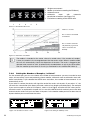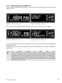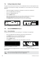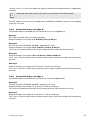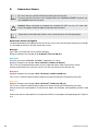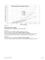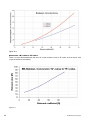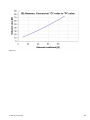
1
Operating Instructions Made in Switzerland ... more than 50 years of know-how you can measure! Proceq SA Ringstrasse 2 Postfach 336 CH - 8603 Schwerzenbach Switzerland Tel.: +41 ( 0 )43 355 38 00 Fax: +41 ( 0 )43 355 38 12 E - Mail: [email protected] Proceq USA, Inc. 117 Corporation Drive Aliquippa, PA 15001 Phone +1 724 512 0330 Fax +1 724 512 0331 E - Mail: [email protected] Proceq Asia Pte Ltd 12 New Industrial Road #02 - 02A Morningstar Centre Singapore 536202 Phone +65 - 6382 - 3966 Fax +65 - 6382 - 3307 E - Mail: [email protected] www.proceq.com Subject to change without notice. Copyright © 2007 by Proceq SA, Schwerzenbach 2 820 34 101E ver 04 2008 © 2007 by Proceq SA Table of Contents 1 Safety 5 1.1 1.2 1.3 1.3.1 1.4 General information Liability Safety Instructions General information Standards and Regulations Applied 5 5 5 5 6 2 Product description 7 2.1 2.2 What is new in the SilverSchmidt, compared to the Classic Schmidt Hammer? Product family 7 9 3 Components of the SilverSchmidt 10 4 The Display Window 12 5 Operation Modes of the SilverSchmidt 13 5.1 5.2 Checking the current Settings Single Impact Mode - Performing a RESET 13 14 6 The User-Interface of the SilverSchmidt 6.1 6.2. 6.3 6.4 Philosophy of the User-Interface Accessing the SELECTOR Working with the Selector Scrolling Between Icons and Selecting Menus 16 17 17 18 7 Setting the Parameters One by One 19 7.1 7.2 7.2.1 7.2.2 7.3 7.3.1 7.3.2 7.3.3 7.4 7.5 7.5.1 7.5.2 7.5.3 7.5.4 7.6 Select “UNITS” Working with “PRESETS” Recalling PRESETS Programming / Customizing PRESETS Select “STATISTICS” Selecting an Averaging Mode Setting the Number of Samples, “n-Select” Measuring with the ASTM norm Setting Carbonation Depth Select CONVERSION Curves Curve Selection Conversion Curves for Type N Conversion Curves for Type L Notes to Conversion Curves Select FORM FACTORS © 2007 by Proceq SA 16 19 20 20 20 21 21 22 23 24 24 24 25 25 26 26 3 4 8 Acquiring a Series of Measurements 8.1 8.2 8.3 8.4 8.5 8.6 Averaging and Converting to Compressive Strength Acquiring the Data Manual Cancellation of Outliers Termination of the Series and Averaging Exiting Averaging Mode REVIEW Mode 9 Maintenance 9.1 9.2 9.3 Function Check Cleaning and Maintenance Hints on How to Obtain Consistent Results 28 28 28 29 30 31 31 33 33 33 34 10 Alerts and What to do 35 10.1 Charging the SilverSchmidt 36 11 Technical Data of the SilverSchmidt 11.1 11.2 11.3 Mechanical Data Electrical Data Useful Ranges 12 Units, Components and Accessories 12.1 12.2 12.3 12.4 Units Components Standard Accessories Accessories (Optional) 13 Appendixes A B C D Operating Modes Menu Structure Considering Carbonation Depth Conversion Curves 14 Product Registration 37 37 37 37 38 38 38 38 38 39 39 40 41 42 46 © 2007 by Proceq SA 1 Safety 1.1 General information The concrete test hammer SilverSchmidt is designed according to state-of-the-art technology and recognized safety regulations. Please read through these operating instructions carefully before initial start-up. They contain important information about safety, use and maintenance of the concrete test hammer. 1.2 Liability Our "General Terms and Conditions of Sale and Delivery" apply in all cases. Warranty and liability claims arising from personal injury and damage to property cannot be upheld if they are due to one or more of the following causes: ○ Failure to use the concrete test hammer in accordance with its designated use. ○ Incorrect performance check, operation and maintenance of the concrete test hammer. ○ Failure to adhere to the sections of the operating instructions dealing with the performance check, operation and maintenance of the concrete test hammer. ○ Unauthorized structural modifications to the concrete test hammer. ○ Serious damage resulting from the effects of foreign bodies, accidents, vandalism and force majeure. All information contained in this documentation is presented in good faith and believed to be correct. Proceq SA makes no warranties and excludes all liability as to the completeness and/or accuracy of the information. For the use and application of any product manufactured and/or sold by Proceq SA explicit reference is made to the particular applicable operating instructions. 1.3 Safety Instructions 1.3.1 General information ○ Perform the prescribed maintenance work on schedule. ○ Carry out a performance check once the maintenance work has been completed. ○ Handle and dispose of lubricants and cleaning agents responsibly. 1.3.2 Unauthorized operators The concrete test hammer is not allowed to be operated by children or anyone under the influence of alcohol, drugs or pharmaceutical preparations. Anyone who is not familiar with the operating instructions must be supervised when using the concrete test hammer. 1.3.3 Labelling in the manual The following icons are used in conjunction with all important safety notes in these operating instructions. ! Danger! This note indicates a risk of serious or fatal injury in the event that certain rules of behaviour are disregarded ! Warning! This note warns you about the risk of material damage, financial loss and legal penalties (e.g. loss of warranty rights, liability cases, etc.) © 2007 by Proceq SA 5 ! i 1.4 6 Caution! Dangers that can lead to major injuries or substantial damage to property This denotes important information Standards and Regulations Applied ○ ISO/DIS 8045 International ○ EN 12 504-2 Europe ○ ENV 20 Europe ○ BS 1881, part 202 Great Britain ○ DIN 1048, part 2 Germany ○ ASTM C 805 USA ○ ASTM D 5873 (Rock) USA ○ NFP 18-417 France ○ B 15-22 5 Belgium ○ JGJ/ T 23-2001 China ○ JJG 817-1993 China © 2007 by Proceq SA 2 Product description 2.1 What is new in the SilverSchmidt, compared to the Classic Schmidt Hammer? The SilverSchmidt is an integrated electronic Schmidt hammer, featuring greater ease of use and extended range. The readings are displayed and can be automatically converted into compressive strength, considering the user settings like different conversion curves, corrections for carbonation and specimen size and shape (form factor). Robust Measurement System – The New "Q"-value The SilverSchmidt measures the true rebound coefficient, the so-called “Q”-value. It represents the physical rebound coefficient: Q = 100 ⋅ Energyrestored Energyinput The SilverSchmidt measures the velocity of impact and of rebound, immediately before and after the impact, computing the fraction of energy restored by the specimen under test. The “Q”-value is virtually free of error sources inherent in traditional concrete test hammers measuring the “R”-value, which is the mechanical travel of the mallet on rebound. The “Q”-value is therefore less dependent on friction on the guide rod, the influence of gravity during the travel of the drag pointer and the relative velocity between unit and specimen. The “Q”-value, respectively the velocity of impact and rebound, is measured optically. This makes the use of a drag pointer, which is affected by friction, redundant. The “Q”-scale differs slightly from the traditional “R” scale. However the SilverSchmidt has a conversion implemented that allows the user to work with the traditional “R”-value. The “Q“-value allows for an extended conversion range, at both ends of the scale. At the high end, the strength vs. “R”-value function gets very steep. The mechanical hammer has difficulties differentiating at “R”-values above 60. At the low end of the scale, friction and gravity often approach the same value as the restored energy, therefore errors can be larger. Angle Independent Operation The “Q”-value needs no correction for the impact direction. There is no need to refer to impact direction conversion curves as required with all other concrete test hammers. © 2007 by Proceq SA 7 Extended Conversion Range The “Q”-value allows an extended conversion range, at both ends of the scale. Curves descri-bing modern concrete mixtures are stored in the unit. Compliance with Industry Standards Data collection and statistical evaluation are user-selectable in accordance with major industrial standards. All measurements are stored in memory and can be reviewed. All Readings Qualified Actual impact energy is measured in Nm, i.e. every reading is qualified whether in range or not. The impact energy is monitored and a warning is displayed when it is out of range. User Interface The SilverSchmidt features an icon based, language independent user interface that allows you to control the unit by a single button and by tilting it sideways to scroll between the menu items. Ease of Operation The result of the measurement is directly displayed on the LCD screen in N/mm2, kg/cm2, “R”, “Q” or psi. Custom presets of test parameters for various testing scenarios can be stored and later recalled. Low Power Consumption The SilverSchmidt features automatic wake-up and sleep modes keeping its power consumption to a minimum. The lithium polymer accumulator in the unit will last for many years without replacement. A single charge will last for over 1’000 impacts. Charging is accomplished via a standard USB cable. Extended Lifetime The unit is tightly sealed all-around to ensure an extended lifetime. All mechanical parts are coated or tempered to high standards. ! 8 Caution! Do not open the unit, be careful when changing the plunger and do not lubricate. © 2007 by Proceq SA 2.2 Product family There are two major versions of SilverSchmidt B and U. The "B" version is the basic version and the "U" version has extended memory and the capability to communicate with a PC via the USB port. It is also supplied with the Hammerlink software which allows further processing of the collected data. Each type B and U is available with the standard imact energy and a low impact energy. This gives the four models currently available. BN Basic version with normal impact energy . UN PC communication version with normal impact energy. BL Basic version with low impact energy. UL PC communication version with low impact energy. The features described in this manual apply to both the B and U types. The additional PC communication features possible with the U version are described in the separate Hammerlink Operating Instruction Manual. © 2007 by Proceq SA 9 3 Components of the SilverSchmidt Full electronic module Housing Full mechanical module type N Figure 3-1.1 Major components of the SilverSchmidt 10 © 2007 by Proceq SA Parts 1 SELECT button 7.1 Battery board incl. battery 2 Cover for USB port 8 Mechanical module complete 4 Plunger complete 9 Hammer guide bar and guide disc 5 Guide sleeve complete 10 Impact spring 6 Housing 11 Loading spring holder complete 7 Electronic module complete 12 Loading spring 13 Hammer mass Turn guide sleeve to the stop Figure 3-1.2 Complete part list of the SilverSchmidt 4 5 2 6 3 1 Figure 3-2 Accessible parts of the SilverSchmidt 1. SELECT button 2. USB port © 2007 by Proceq SA 3. LCD display 4. Plunger 5. Guide sleeve (cap) 6. Housing 11 4 The Display Window ZERO MARKER ANALOG SCALE “50” MARKER UNIT ALERT SYMBOL “Q” VALUE IMPACT COUNTER SINGLE IMPACT OR TOTALIZER OR SERIES OF “n” Figure 4-1 The display window of the SilverSchmidt A typical display after an impact shows: ○ The actual “Q”-value with a two and a half digit number ○ A pseudo-analog scale mimicking the mechanical drag pointer. ○ A counter either displaying the last two digits of the 4 digit totalizer or the actual number of valid impacts in a series of measurements. Throughout this manual you will come across all kinds of display contents. You will learn the graphical user interface that allows you to control the SilverSchmidt unit in a quick and intuitive way. 12 © 2007 by Proceq SA 5 Operation Modes of the SilverSchmidt The SilverSchmidt unit distinguishes three modes of operation: Impact mode: Used for acquiring a single rebound value or a series of consecutive rebound values. There are two impact modes. ○ Single impact ○ Measurement series Set-up mode: Used to enter settings to convert a series of consecutive rebound values to compressive strength. It can also be used to save the current settings as user definable presets. Review mode: Used to recall the last 20 results of either single impacts or measurement series. i 5.1 The structure of the operation modes is shown in Appendix A and in the Quick Reference Guide. Checking the current Settings The current settings will be displayed when you apply the end of the plunger against the concrete (or any firm) surface and slightly push (TIP). You can review the settings at any time – they are displayed momentarily and will not affect any current testing or settings. The display format is shown in Figure 5-1. Units Preset if any... Statistics mode and number Carbonation depth Conversion curve Form factor F i g u re 5 - 1 Display showing all 6 settings In chapter 7 you will learn how to program the settings of your SilverSchmidt to give you a read-out in the way that best suits your application. © 2007 by Proceq SA 13 5.2 Single Impact Mode - Performing a RESET This chapter addresses the use of the SilverSchmidt as a classical hammer, to provide a single rebound value for a quick estimate. More advanced features are described in chapter 7. The SilverSchmidt can be reset by performing an impact while the SELECT button is pressed. The display is set to “Q” and all conversion parameters are reset. To indicate the RESET status, the display will look as shown in Figure 5-2: with the serial number of the unit, the “Q”-value and the last two digits of the totalizer. Figure 5-2 Display after RESET Figure 5-3 SETTINGS after RESET Now check the settings again by depressing the plunger against any surface. The default settings as illustrated in Figure 5-3 will appear on your display. The SilverSchmidt is now programmed to work in the “Single Impact” mode. The following parameters have been set: Unit (Q), Preset (..., none), Statistics Mode (..., single measurement), Carbonation (0.0 no carbonation), Conversion Curve (pqb, Proceq-B-Curve), form Factor (1.0, for Curve ISO 150 mm). The totalizer keeps track of all impacts and is never zeroed. The RESET procedure described here need only be done once (or in the rare case of a system error). As long as your SilverSchmidt displays a ”Q”, a value and two dots (meaning individual impacts) as well as the two digit counter you are in “Single Impact” mode. This display format is maintained for 5 impacts following a RESET. This feature will let you verify the number of impacts your SilverSchmidt has done along with the “Q”-value. After 5 impacts following RESET the display will change to the format which includes a pseudo analog scale for the “Q”-value unless it exceeds 70. 14 © 2007 by Proceq SA Figure 5-4 Display after RESET and first impact Figure 5-5 Measuring in “Q” on concrete i The SilverSchmidt has a resolution of 0.5 on individual “Q” readings. The totalizer advances in increments of one and is displayed in full (4 digits). A typical result taken in “Single Impact” mode looks like that illustrated in Figure 5-5: (Please note that the scale above the number is animated, indicating that there are still some components moving internally). If registering “Q”-values is all that is required, please proceed to chapter 9. However, if the advanced features are of interest, please continue reading. i Note ! Performing a reset with the U-version will display the USB symbol during the boot-up. © 2007 by Proceq SA 15 6 The User-Interface of the SilverSchmidt 6.1 Philosophy of the User-Interface The user-interface of the SilverSchmidt is based on a straightforward menu structure. Each menu item has its own descriptive ICON making it language independent. i The complete menu structure can be found in the appendix B. There are five ways in which the user can interact with the SilverSchmidt ○ TILT – Tilting the device means that you raise the left side (plunger side) of the device to scroll to the icons to the left of the “centered” icon or you raise the right side of the device (SELECTOR button side) to scroll to the icons to the right of the “centered” icon. ○ ROLL – Rolling the device means that the device remains in the horizontal position, but the display is rolled away from you or towards you. ○ SELECT - Press the SELECT button. ○ TIP – Depress the plunger a short distance, but not enough to trigger it. ○ IMPACT – Depress the plunger until it triggers. These simple actions are all that is required to navigate around the menu, set-up the SilverSchmidt, perform measurements and review results and settings. How this is done precisely is described in the following chapters. Click the SELECT button, and a new window will appear on the display. Now tilt the unit sideways (or in certain cases roll it towards and away from you), and the display will respond either by moving the list of icons or by a scrolling bar. i As the symbols lock into the center position their shade reverts to indicate their selection. Center the desired icon – or move the scroll bar to the value of choice, click the SELECT button for a second time, and the desired menu or parameter will be selected. In the next menu continue with your selection and choose it by clicking SELECT. i 16 • Doing an impact will always take precedence, i.e. the SilverSchmidt will acquire the next rebound value. • Once you have made your selection you will return to the SELECTOR. © 2007 by Proceq SA 6.2. Accessing the SELECTOR t ○ From Single impact mode press the SELECT button to access the SELECTOR. ○ From measurement series mode press the SELECT button. This will take you to the STATISTICS Dialog menu. Scroll to the SELECTOR icon and press SELECT again (Figure 6-0). Figure 6-0 Selector icon ○ From review mode – Roll the device away from you to scroll down to the selector icon and click SELECT to return to the SELECTOR. If you have entered a menu inadvertently, the SilverSchmidt will automatically revert to the SELECTOR, after approximately 5 seconds if no further action is taken. The concept will be further explained in chapter 7 where you will be taken through the steps of selecting various parameters. 6.3 Working with the Selector Apply the principle of the user-interface described above to configure the SilverSchmidt for an advanced measuring task (i.e. to give you a read-out in compressive strength, considering a set of parameters or to do a series of measurements with statistics): Figure 6-1 Controlling the SilverSchmidt with the single button interface with gloves ○ Hold the SilverSchmidt horizontally in front of you as shown in Figure 6-1. ○ Enter Set-up mode by clicking the SELECT button. ○ The SELECTOR will appear on the display (see Figure 6-2). The portion of the list of icons visible at first is the central section of the complete list as shown in Figure 6-4. Scroll and click SELECT on the desired icon as described in detail below. © 2007 by Proceq SA 17 i Please thoroughly familiarize yourself with this process (as this user interface principle is used throughout the operation of this instrument. Figure 6-2 Portion of “selector”, initially visible Figure 6-3 entering set-up mode Form Factors Conversion Carbonation Review Statistics Presets Units In the left window the REVIEW icon is centered – the right window illustrates the transition to the STATISTICS icon. Figure 6-4 The Selector The left group of icons (1 to 3) and the right group (5 to 7) refer to mathematical or physical properties, the center icon (4) allows a review of the last 20 results. 6.4 Scrolling Between Icons and Selecting Menus When you first click the SELECT button, the display will look as shown in Figure 6-2, i.e. with the “REVIEW” icon in the middle and cropped on either side. Tilt the unit to the left and the icons will scroll to the right (see note below). Through this mechanism you will be able to position the desired icon, e.g. “CARBONATION” to the center of the display. Click the SELECT button a second time and you enter the “CARBONATION” menu. In the same way you can select any of the other menus or parameters. 18 i Tilt to the left here means dropping the left side and raising the right side to move to the icons to the right of the centered position. i When entering into any menu, the icon that is initially “centered” is always the last one that was selected. © 2007 by Proceq SA 7 Setting the Parameters One by One We will now explain each icon and it’s associated menus from left to right. This sequence has been chosen for the sake of instruction - you can program the features according to your needs, in any order or you can bypass the sequence altogether by recalling one of the user-definable presets (see chapter 7.2) 7.1 Select “UNITS” Your SilverSchmidt will convert from „Q“-values to compressive strength at the end of every measurement series if you select the appropriate unit (N/mm2, kg/cm2 or psi). If you do not specify the units after a RESET, the SilverSchmidt will automatically give you a reading in Q. There is the possibility to work in “R” but it is more effective to switch to “Q”. i ○ Access the SELECTOR (see chapter 6.2) ○ Scroll to the leftmost icon by tilting the unit to the right and letting the “UNITS” icon float to the center of the display (see Figure 7-1). ○ Click the SELECT button again to enter the “UNITS” menu. Figure 7-1 SELECTOR with “UNIT” icon centeredFigure 7-2 Menu ”UNIT” centered on N/mm2 The symbols in Figure 7-2 mean the following: ○ ○ ○ ○ ○ R Q N/ k/ P/ i Rebound value “Q”-value N/mm2 (Please note: N/mm2 is the same as Mpa) kg/cm2 psi (Please note: when psi is set as the unit then carbonation and form factor will be in inches.) The square symbol stands for “area”. Scroll to the desired unit (in the case shown in Figure 7-2 it is “N/mm2”) and click the SELECT button. The desired unit is stored and you are back in the SELECTOR. i Whenever you set a different unit this will take effect for the following samples only, the previous results, stored in the memory stack, are not affected by changing the units or any other change of settings. © 2007 by Proceq SA 19 7.2 Working with “PRESETS” 7.2.1 Recalling PRESETS Figure 7-3 “PRESETS” icon centered Figure 7-4 Menu ”PRESETS” centered on F0 The “PRESETS” menu allows you to recall customized settings of all parameters, giving you a shortcut to your most frequently used configurations of the SilverSchmidt unit. ○ Access the SELECTOR (see chapter 6.2) ○ Scroll to the PRESET icon by tilting the unit to the right until it floats to the center of the display. ○ Click SELECT button to enter the PRESETS menu. ○ Scroll to the desired preset. ○ Click SELECT a second time. The desired preset is loaded and you are back in the SELECTOR. Remember you can verify your current settings at any time by depressing the plunger thereby recalling the SETTINGS display (e.g. see Figures 5-1 or 5-3). i F0 Preset - Factory Preset (Read only): This set of parameters reflects the standard of the territory you work in if it is known. In Europe it corresponds to the set called for by the European standard 12504/2 (median, minimum number of impacts = 9, 20% criteria) N/mm2, Proceq-B curve adapted to “Q”-value, Cube 150 x 150 x 150mm, Carbonation acc. actual situation. In the US it corresponds to ASTM C805. If the local standard is not known then F0 will be set to the European standard. C1, C2, C3: Customer Presets (can be customized) i If you proceed to change a parameter, you are not in the preset anymore. So if you often use the territory standard but with, for example, another number of impacts, choose F0 change the number of impacts as explained in chapter 7.3.1 and save this in one of the presets C1, C2 or C3. 7.2.2 Programming / Customizing PRESETS The principle behind this option is very simple: Once you have put together a set of parameters that suit your task, assign them to a custom preset in C1, C2 or C3 so they are memorized and can be recalled whenever needed. To save a set of parameters after you have already worked with them, the sequence for programming is as follows: ○ 20 Access the SELECTOR as above and scroll to center the presets icon. © 2007 by Proceq SA ○ Press the SELECT button for approximately two seconds to enter the “PRESETS” menu in the programming mode. This means you are writing data into the location of your choice, overwriting what was previously programmed. If this is not what you want to do, wait for five seconds without doing anything and you will return to the SELECTOR. ○ Scroll to desired preset location C1, C2 or C3, and click the SELECT button. For example in Figure 7-5 below C1 in the center of the display is the desired preset location. i F0 is a read only location and cannot be changed. i There is no alert to confirm if you really want to overwrite the parameters previously stored in the preset locations. t Figure 7-5 PRESET menu: Writing the current settings into C1. C1 is in the center of the display Locations C1 to C3 are inverted to alert you that you are in write mode. 7.3 Select “STATISTICS” Figure 7-6 Selector with „STATISTICS“ icon centered The “STATISTICS” sub menu is a little more involved than the previous ones, since it allows you to choose two sets of parameters. Unless you choose to work in Single impact mode or the ASTM mode, the menu consists of two layers. 7.3.1 Selecting an Averaging Mode The first layer lets you choose the averaging mode. You can choose between five different averaging modes: The statistics menu will ask you for your choice with the following window. Center the desired icon and click the SELECT button. © 2007 by Proceq SA 21 1. 2. 3. 4. Single measurement Median (evaluation according the EN Norm) Arithmetic mean Arithmetic mean with automatic cancellation of outliers (see Figure 7-8) 5. Evaluation according to the ASTM norm 1 2 3 4 5 Figure 7-7 Averaging mode menu Total nos. of series Nos. of values considered for Statistics Nos. of outliers automatically deleted (e.g. from 16 values 2x2 outliers are deleted). Figure 7-8 Automatic cancellation i 7.3.2 The median is intended as the center value of a sorted series. If the number of samples is even, the median is the average between the two center values. When in median mode the unit will automatically check the dispersion of the data. The result is flagged to be rejected when more than 20% (mathematically rounded down or up) of the values differ from the median by more then ±6.5 units (as mentioned in the standard EN 12504-2). Setting the Number of Samples, “n-Select” On the second layer you can now choose the number of measurements you want to make for one series, of course only if you have previously chosen median, arithmetic mean or arithmetic mean with outlier cancellation. If you selected the ASTM norm evaluation, the number of measurements is set automatically to 10. If you select a number, the device will signal the end of the series at that point. If you select “n”, the unit waits for a termination (this allows you to do a series of any length up to 99 impacts). For example if you want to acquire a series of 15 impacts, select n=16 or higher and after the 15th value you terminate the series as explained in chapter 8.4. In case of the ASTM statistic method, you are not able to terminate the series until you have done 10 impacts. In the median mode you have to do at least 9 impacts before you can terminate the series. Figure 7-9 “Scroll bar n-select”: n=16 22 Figure 7-10 setting an arbitrary series © 2007 by Proceq SA 7.3.3 Measuring with the ASTM norm If you choose the ASTM norm evaluation, at the end of your measurement series you will get the following screen. Figure 7-11 Summary screen one Figure 7-12 Summary screen two If the norm cannot be fulfilled with the measurement series, the screens will look as follows: Figure 7-13 Summary screen one Figure 7-14 Summary screen two Screen one indicates that more than 2 values (20% from 10 values) vary by more than is allowed from the arithmetic mean. The second screen shows the calculated mean in Q, the standard deviation in Q and the corresponding PSI value. i The evaluation according the ASTM C805 norm: First the arithmetic mean from all ten measurements will be calculated. Then each measurement is checked to see if it varies by more than 6R-values (resp. 6.5 Q-values) from the arithmetic mean. From the remaining values the arithmetic mean is calculated again. If more than 20% were cancelled, the whole series is deemed invalid. This is indicated on the SilverSchmidt by the >20% symbol, but nevertheless the PSI value is calculated and displayed on the next screen. © 2007 by Proceq SA 23 7.4 Setting Carbonation Depth The age of the concrete and the thickness of the carbonated surface can lead to significant overestimations of the compressive strength. Two methods are in use to correct the “Q“-value (see Appendix C). ○ Determine the depth of carbonation (in millimeters or inches) with an indicator kit. ○ Access the SELECTOR (see chapter 6.2) ○ Select the “CARBONATION” icon. ○ Click the SELECT button. ○ When entering the Carbonation menu the scroll bar will point to the last value set. (Scroll to the appropriate value (in increments of 0.5 mm, 2/100 in). ○ Click SELECT again after positioning the scroll bar to the desired depth. Figure 7-15 “CARBONATION” icon centered Figure 7-16 Sub-menu ”CARBONATION” 7.5 Select CONVERSION Curves 7.5.1 Curve Selection To select any of the conversion curves (see Figure 7-17 and Figure 7-18 respectively): ○ Access the SELECTOR (see chapter 6.2) and center the conversion icon. ○ Click SELECT button to enter the CONVERSION menu. ○ Scroll sideways by tilting unit and center your choice. ○ Click the SELECT button. ○ Click SELECT a second time when your choice appears in the center. Figure 7-17 “CONVERSION” icon centered Figure 7-18 Menu “CONVERSION” on Proceq Curve “C” The SilverSchmidt comes programmed with a variety of conversion curves. This applies for the two types N and L. i 24 All curves are only valid for Portland cement types of concrete. The curves with all the details are shown in Appendix D. © 2007 by Proceq SA The new curves L, C and H (see below) are based on extensive tests performed by an independent institution. i Information on the derivation of the curves can be found on the Proceq website. For each type the classical curves Proceq B from the ORIGINAL SCHMIDT hammer are also adapted to the new “Q”-value. 7.5.2 Conversion Curves for Type N The SilverSchmidt N is provided with four conversion curves (see Appendix D). Proceq L (only when measured with the mushroom plunger) Range of compressive strength: 5 to 30 N/mm2 (725 to 4’400 psi) Proceq B Classical curve from ORIGINAL SCHMIDT adapted to “Q”-value Range of compressive strength: 10 to 70 N/mm2 (1’450 to 10’200 psi) This curve was established more than 50 years ago and shows rather conservative values. Proceq C Range of compressive strength: 10 to 110 N/mm2 (1’450 to 16’000 psi) This curve is valid for wide range of Portland cement type of concrete including self compacting concrete. Proceq H Range of compressive strength: 70 to 170 N/mm2 (10’200 to 24.650 psi) This curve is valid for a wide range of Portland cement type of concrete including self compacting concrete. 7.5.3 Conversion Curves for Type L The SilverSchmidt L is provided with two conversion curves (see Appendix D). Proceq B Classical curve from ORIGINAL SCHMIDT adapted to “Q”-value Range of compressive strength: 18 to 70 N/mm2 (2’600 to 10’200 psi) This curve was established more then 50 years ago and shows rather conservative values. Proceq C Range of compressive strength: 8 to 110 N/mm2 (1'160 to 16’000 psi) This curve is valid for wide range of Portland cement type of concrete including self compacting concrete. © 2007 by Proceq SA 25 7.5.4 i ! 7.6 Notes to Conversion Curves All conversion curves are referenced to a 150 x 150 x 150 mm cube. Therefore you must select the appropriate form factor (see chapter 7.6) when referring to other shapes of test specimens. Warning! The conversion curves are established according to the best practices available. However, it is recognised that many parameters (concrete mixture, age of the concrete, carbonation depth, etc.) can strongly affect the conversion. In critical cases it is therefore necessary to: ○ generate your own conversion curves ○ verify the measurements by extracting a sample probe. Select FORM FACTORS Figure 7-19 “FORM FACTOR” icon centered Figure 7-20 Menu “FORM FACTOR” on 150 mm cube By means of the form factor, it is possible to convert strength values for a particular specimen form to those of a different form/dimension. In countries where the 28 day strength is not determined on concrete cubes with 150 mm edge length, our table values have to be multiplied by this form factor in order to obtain comparable results. The same form factor would have to be applied when for instance, the test specification prescribes cubes with 150 mm edge length but the effective test in the compressive testing machine is carried out with different specimen forms. The SilverSchmidt unit uses a 150 x 150 x150 mm cube as standard reference to convert from the averaged “Q”-factor to compressive strength. Since, depending on your application you may make reference to different dimensions and geometry; a variety of shapes are selectable for your conversion. To set a specific form factor proceed as follows (7-19, respectively Figure 7-20): 26 ○ Access the SELECTOR and center the “FORM FACTOR” icon. ○ Click the SELECT button and scroll to the appropriate value. Seven values are offered. 1.0 (for cube 150x150x150 mm) is in the center initially. In addition, the form factor is displayed in numbers on the right. ○ Click the SELECT button again when the desired factor is centered. © 2007 by Proceq SA Drilled core Cube 0,95 Ø 50 x 56 mm dia 2 x 2.2 in Ø 100 x 100 mm dia 4 x 4 in Cylinder 100 x 100 x 100 mm 1,03 4 x 4 x 4 in 200 x 200 x 200 mm 1,04 1,02 8 x 8 x 8 in 1,00 0,86 0,81 Ø 100 x 200 mm dia 4 x 8 in Ø 150 x 300 mm dia 6 x 12 in 150 x 150 x150 mm 6 x 6 x 6 in Ø 150 x 150 mm dia 6 x 6 in 1,00 0,95 Ø 200 x 200 mm dia 8 x 8 in 0,86 Form factors 300 x 300 x 300 mm 12 x 12 x 12 in Figure 7-21 Form factors © 2007 by Proceq SA 27 8 Acquiring a Series of Measurements 8.1 Averaging and Converting to Compressive Strength The SilverSchmidt will conveniently give you a conversion once you have programmed the various settings as described in the previous chapter. Once the various parameters (unit / number and mode of samples to be averaged / carbonation depth / conversion curve / form factor) are set the SilverSchmidt will keep them memorized until you make a change (even when the unit goes into sleep mode). i 8.2 Work with presets as described in chapter 7.2. instead of setting the parameters before every task. In fact only parameters you want to change must be set prior to an individual measuring task. Acquiring the Data As with the Single impact mode, press the SilverSchmidt against the surface to be tested (TIP). When you depress on the plunger the settings will temporarily be displayed (Figure 5-1). Apply pressure until the impact is released and your first measurement will be recorded (Figure 8-1). i Individual impacts will be registered as “Q“-values. The conversion to compressive strength is done only after completion of the series. Figure 8-1 Acquiring the first sample of a series Figure 8-2 Acquiring the second sample of a series The letter “n” indicates that the counter is keeping track of the number of samples acquired in the current series. 28 © 2007 by Proceq SA 8.3 Manual Cancellation of Outliers Individual readings that are obvious outliers, as the might occur by hitting a soft spot, a hole or a pebble can be eliminated. Proceed at a pace that allows you to monitor the display while measuring. Please note that only the most recent reading can be canceled. i If the most recent reading (Figure 8-3) is clearly out of range: ○ Click SELECT to enter to the “STATISTICS DIALOG WINDOW” (Figure 8-4.) ○ It appears with the Sum symbol centered; Tilt the unit to center the “TRASH” icon (Figure 8-5). ○ Click SELECT to cancel the last reading. The display responds by wiping out the reading (Figure 8-6) indicating that the cancellation has occurred; at the same time the counter has been decreased by one. Single Impact Sum Trash Selector Figure 8-3 Outlier - to be cancelled manually Figure 8-4 Stat dialog Box on “Average” (Sum) symbol Figure 8-5 Stat dialog Box on “Cancel” (trash can) symbol © 2007 by Proceq SA Figure 8-6 Display after cancellation of outlier 29 After having cancelled a result, proceed normally with your impacts until you have acquired the specified number of valid samples. If you wish to shorten the length of your series you can click on “Sum” after entering the Statistics dialog box at any time – this allows you to make a series of any arbitrary length. The SilverSchmidt will keep track of the number of valid impacts and it will alert you when you are ready to average and convert. For example, if your test series required a series of 20 impacts; having reached this number the “n” symbol will be inverted suggesting that the buffer is full (Figure 8-7). i If you make additional impacts the unit will not register them. i The impact totalizer will register all impacts since its scope is to give you information about the wear of the unit. Figure 8-7 Display of last value in series of 20 Figure 8.4 8-8 Stat (Sum) symbol dialog Box on “Average” Termination of the Series and Averaging This section describes how to terminate a measurement series and how the results are represented. ○ Click SELECT to enter to the “STATISTICS DIALOG WINDOW” (Figure 8-8) ○ Click on the “Sum” symbol (unless the actual reading is an outlier in which case you delete it as described above). The result will appear as in Figure 8-9 and Figure 8-10 respectively. Figure 8-9 Display of median after a series of Figure 8-10 Arithmetic mean after a series of impacts; compressive strength expressed in N/mm2 impacts; compressive strength expressed in psi 30 © 2007 by Proceq SA If you are interested to see additional information tilt the unit and the display as shown in Figure 8-11 will appear. Figure 8-11 Status after series is completed 8.5 Exiting Averaging Mode If, after having completed a series, you want to perform a new one, simply make another impact and the SilverSchmidt will start the new series with the counter reset to one. If you wish to change the parameters for your next series click SELECT, scroll to the SELECTOR icon and click SELECT a second time (Figure 8-12). Should you want to revert to making single measurements a shortcut symbolized “1 1” is provided (Figure 8-13). Figure 8-12 Statistics Dialog Window with icons Figure 8-13 to proceed in Single impact mode centered to return to SELECTOR or… 8.6 REVIEW Mode The SilverSchmidt features a REVIEW mode that visualizes the last 20 readings. Readings can be single values or averages. To enter the “REVIEW” mode access the SELECTOR, scroll to the middle icon and click SELECT from the SELECTOR. Figure 8-14 “REVIEW” in center of display Figure 8-15 Bottom of Review stack Upon entering the “REVIEW” mode, you will see the last series or individual readings in the middle row of the display as illustrated in Figure 8-15. The most recent value is at the bottom of the stack. Still below is a row containing the list of SELECTOR icons, it allows you to return to the SELECTOR. To visualize more readings, roll the SilverSchmidt towards you, and the different rows will scroll from bottom to top. Figure 8-16 shows more sections of the result stack. © 2007 by Proceq SA 31 The SilverSchmidt lets you review the last 20 readings. When you reach the top of the stack, the SELECTOR icons are displayed (Figure 8-16 top). A scroll bar on the right side points to the part of the stack displayed in the window. 1.) 2.) 3.) The vertical scroll bar on the right indicates the position of the row in the list. If you are in Single impact mode, the list will contain individual impacts in Q or R. To the left is the value of the totalizer at the beginning of each series or single impact. side Figure 8-17 Zoom into the middle row (#2187) Figure 8-16 Top, middle and bottom of stack If you have acquired a series of values applying statistics, the stack will show the averaged value in the unit you have chosen. You can “zoom into” the middle row by pressing the SELECT button and the display will show the values stored and already shown at the completion of that measuring series (Figure 8-17). From here further information about this series can be accessed by tilting the unit as described in section 8.4. Click the SELECT to return to the review stack (Figure 8-16). To leave the REVIEW mode, either trigger an impact (you’re back in acquisition mode), or scroll to a row of icons and jump back to the SELECTOR 32 © 2007 by Proceq SA 9 Maintenance 9.1 Function Check The functional check of your SilverSchmidt is based on two main tests. Permanent Monitoring of the Impact Energy The SilverSchmidt measures the impact energy with every impact. If the impact energy is under a defined level an error message is displayed. In this case the hammer has to be serviced and should be sent back to the service point. This test gives you an immediate warning if the SilverSchmidt isn’t working correctly. Figure 9-1 Impact Energy Consistency Check The SilverSchmidt can be checked for proper operation by the aid of a test anvil. If you are already in possession of a corresponding test anvil, perform a measurement series of more than nine impacts with your new and calibrated SilverSchmidt. Note the result for comparison against future consistency checks. Alternatively a new and precalibrated test anvil can be ordered from PROCEQ. Please contact PROCEQ or your sales contact for further information. A consistency check should be carried out after every 500 impacts to ensure accurate readings. If the mean value differs by more than +/- 3Q from the initial value, the hammer has to be serviced and should be sent back to the service point. i 9.2 Because of the new design of the SilverSchmidt, both types N & L behave differently than the Original Schmidt Hammer on some test anvils. Cleaning and Maintenance Your SilverSchmidt unit has been designed to give effective results for several 1’000 impacts. After use, clean the external parts, in particular wipe any dust off the plunger and display window, being careful not to scratch the glass. Be careful when taking off the plunger (to exchange it for a different type) to prevent dirt from entering the unit. © 2007 by Proceq SA 33 9.3 Hints on How to Obtain Consistent Results Use the grinding stone to smoothen the test surface. Perform a few test impacts with the concrete test hammer on this smooth, hard surface before taking any measurements which you are going to evaluate. Perform a consistency check on the test anvil. Figure 9-2 Preparing the test surface Ensure all settings are correctly done as described in chapter 7. Each test surface should be tested with at least ten impacts. The individual impact points must be spaced at least 25 mm apart. You may use the template (accessory from PROCEQ) either to mark the impact points on the surface or fix it to the surface and hit the surface within the holes of the template. Figure 9-3 Positioning the SilverSchmidt Figure 9-4 Triggering an impact Position the concrete test hammer perpendicular to and against the test surface (Figure 9-3). Push the concrete test hammer against the test surface at moderate speed until the impact is triggered (see Figure 9-4). ! 34 Warning! The plunger generates a recoil when it deploys. Always hold the concrete test hammer in both hands, perpendicular to the test surface, before you trigger the impact! © 2007 by Proceq SA 10 Alerts and What to do 1 2 3 4 5 6 7 Figure 10-1 “Low Battery” Figure 10-2 Alerts Figure 10-1 Typical Alert: “Low Battery” in the space between the “Q” symbol and the rebound value. i If there is more than one alert, they will alternate Figure 10-2 Alerts (from left to right): 1 Low battery: Battery will last for approximately another two hours (see also chapter 10.1) 2 Battery full: Is indicated for a few seconds 3 Charging: Is displayed for a few seconds once the USB cable is connected. 4 Unsteady operation: Hold the unit steady and push slowly to avoid excessive motion. 5 Low impact energy: refer to the repair service 6 Optical encoder obstructed: Refer to the repair service 7 Excessive friction: Refer to the repair service The symbols 1 to 3 referring to the battery are self explanatory. Symbols 5 to 7 are alerts that help you identify a problem. The alert will be useful when communicating with the repair service (or in trying to repair the unit yourself) Alerts 4, 5 6, and 7 are indicated after an impact only, thus as shown in Figure 10-1. Alerts 1, 2 and 3 are shown at any time when appropriate. They will be seen at the same position but alone without any other informationon the display. © 2007 by Proceq SA 35 10.1 Charging the SilverSchmidt The SilverSchmidt uses a built-in Lithium Polymer accumulator. In case of a low battery alert, you can still record up to 100 impacts. But be sure to recharge the unit after use or prior to the next session. When the display indicates a low battery, connect the SilverSchmidt to the charger or an “active” (not in standby mode) personal computer. The USB link will supply 100 mA, therefore 90 minutes of charging will bring your SilverSchmidt to its full capacity. The SilverSchmidt has a sophisticated charging circuit so you can either recharge at the end of each working day, having reached low battery indication, or once a week as required. Should your instrument be fully discharged, start with a “RESET” (chapter 5.2) after you have charged it again. i The custom presets are not affected by this “RESET” operation. Battery Status For the battery status three alerts can be displayed. ○ Low battery (see 1 in Figure 10-2) ○ Battery fully charged (see 2 in Figure 10-2) ○ Connected power supply (see 3 in Figure 10-2) In measuring mode these symbols will be displayed at the place for alerts and will start flashing. In all other cases larger symbols will be displayed once for about two seconds on the full display. 36 © 2007 by Proceq SA 11 Technical Data of the SilverSchmidt 11.1 Mechanical Data Impact energy* Hammer mass Spring constant* Spring extension* N–Type 2.207 Nm 115 g 0.79 N/mm 75 mm Dimensions of housing Dimensions (plunger visible part) Weight 55 x 55 x 250 mm (340mm to tip of plunger) 105 x ø15 mm / radius of spherical tip 25mm 600 gram 11.2 Electrical Data Display Power consumption Accumulator duty Charger connection Accumulator capacity 11.3 L–Type 0.735 Nm 115 g 0.26 N/mm 75 mm 17 x 71 pixel; graphic ~13mA measuring, ~4 mA setup and review, ~0.02 mA idle >1000 impacts (before recharging) USB type B (5V, 100 mA) ~150mAh Useful Ranges Operating temperature Storage temperature 0 to 50 °C -10 to 70 °C (*as in Original Schmidt) © 2007 by Proceq SA 37 12 Units, Components and Accessories 12.1 Units Type BN 341 10 000 SilverSchmidt BN UNIT consisting of: SilverSchmidt BN, standard accessories (battery charger with USB-cable, data carrier, carrying strap, grinding stone, chalk, documentation) and carrying case 341 10 001 SilverSchmidt BN consisting of: Housing, electronic and mechanical module Type BL 341 20 000 SilverSchmidt BL UNIT consisting of: SilverSchmidt BL, standard accessories (battery charger with USB-cable, data carrier, carrying strap, grinding stone, chalk, documentation) and carrying case 341 20 001 SilverSchmidt BL consisting of: Housing, electronic and mechanical module Type UN 341 11 000 SilverSchmidt UN UNIT consisting of: SilverSchmidt UN, Hammerlink software, standard accessories (battery charger with USB-cable, data carrier, carrying strip, grinding stone, chalk, documentation) and carrying case 341 11 001 SilverSchmidt UN consisting of: Housing, electronic and mechanical module. Type UL 341 21 000 SilverSchmidt UL UNIT consisting of: SilverSchmidt UL, Hammerlink software, standard accessories (battery charger with USB-cable, data carrier, carrying strip, grinding stone, chalk, documentation) and carrying case 341 21 001 SilverSchmidt UL consisting of: Housing, electronic and mechanical module. 12.2 Components Type N and L 341 10 113 Cover for USB port 341 10 310 Plunger complete 341 10 100 Housing 341 10 200 Electronic module complete 341 10 202 Battery board, incl. battery 341 10 300 Mechanical module complete N 341 20 300 Mechanical module complete L 341 10 320 Hammer guide bar and guide disc 341 10 351 Impact spring type N 341 20 351 Impact spring type L 341 10 355 Guide sleeve type N, complete 341 20 355 Guide sleeve type L, complete 12.3 38 Accessories 340 10 400 SilverSchmidt Anvil 341 80 100 Carrying case complete 351 90 018 USB cable 1.8 m long (6 ft) 341 80 112 USB Charger, global 341 80 208 Data carrier with SilverSchmidt documentation 341 80 203 Carrying strap (loop) 341 80 205 Grinding stone in plastic box 325 34 018 Chalk 341 90 001 Mushroom plunger (for softer material) © 2007 by Proceq SA © 2007 by Proceq SA MEASUREMENT SERIES 4 TIPPING ON THE PLUNGER TEMPORARILY DISPLAYS THE SETTINGS DOING AN IMPACT WILL ACQUIRE THE NEXT SAMPLE, LEAVING THE SETTINGS UNCHANGED 8.5 NUMBERS ARE REFERRING TO THE CHAPTERS OF THE OPERATION INSTRUCTIONS 3 WHEN DOING A SERIES OF MEASUREMENTS “SELECT” GETS YOU TO THE “STAT DIALOG WINDOW” 2 END OF THE SERIES WHEN ACQUIRING SINGLE DATA “SELECT” GETS YOU TO THE SET-UP VIA THE SELECTOR TIP SELECT 8.5 1 2 3 4 5 6 7 LOW BATTERY BATTERY FULL CHARGING UNSTEADY OPERATION LOW IMPACT ENERGY DIRTY ENCODER EXCESSIVE FRICTION 10 ALERTS CANCEL LAST READING DECREMENT COUNTER BY 1 SELECT IMPACT START NEXT SERIES OPENS STAT. DIALOG WINDOW 8.4 IMPACT IMPACT IMPACT IMPACT IMPACT IMPACT IMPACT IMPACT IMPACT 8.2 SELECT 1 IMPACT SELECT SETTINGS (TEMPORARY) TIP FOR DETAILS SEE MENU STRUCTURE 4 CARBONATION CURVES FORM FACTOR SET PARAMETERS 2 JUMP TO SELECTOR 1 2 3 4 5 6 7 RESULT DISPLAY SERIES VALUE SELECT 8.6 & CONVERSION 8.5 STAT. DIALOG SELECT 8.3 SELECT Operating Modes 3 IMPACT 1 SELECT SHORTCUT TO SINGLE IMPACT REVIEW MODE A SELECT SELECT SINGLE IMPACT IMPACT MODE Appendixes UNITS PRESETS STATISTICS SCROLL BY TILTING SET-UP MODE 13 39 B Menu Structure REVIEW MODE SET-UP MODE 8.6 List contains results of series or single measurements. No detail view is possible (and necessary) on single measurements. S C R O L L SETTINGS (TEMPORARY) U P When tipping on plunger SETTINGS are displayed for about 5 seconds. 4 PRESETS (PROGRAM) SELECT SCROLL LEFT OR RIGHT 5 Shows details of series in the row in the middle. D O W N TIP 7.2.2 SELECT O R SELECT SELECT LONG CLICK A click on SELECT the icon list gets you back to SELECTOR IMPACT MODE (see Set-up Mode for series) SELECTOR IMPACT -> change to IMPACT MODE with current settings SELECT SCROLL OROR RIGHT SCROLLLEFT LEFT RIGHT 7.1 R: Classical “R”-value Q: True rebound coefficient N/ : N/mm² K/ : kg/cm² P/ : psi UNIT SELECT 6.2 SELECT 7.6 SCROLL LEFT OR RIGHT SCROLL LEFT OR RIGHT 5 SELECT SELECT SELECT SELECT PRESET RECALL Fo: Factory setting C1 / C 2 / C 3 : Customer settings CONVERSION CURVE SELECT SELECT SCROLL LEFT OR RIGHT 5 SELECT 5 PL: low strength (young concrete, only with mushroom plunger) PB: classical curve PC: new Proceq C curve with extended range PH: high strength concrete 7.4 STATISTICS (METHOD) CARBONATION DEPTH SCROLL LEFT OR RIGHT SCROLL LEFT OR RIGHT 5 SELECT 7.3.2 to program else timeout -> settings remain unchanged STATISTICS (SELECT n) SELECT 5 5 PARAMETERS ARE ONLY CHANGED BY CLICKING SELECT WITHIN 5 SECONDS. OTHERWISE DISPLAY RETURNS TO SELECTOR AND LEAVES PARAMETERS UNCHANGED. SCROLL LEFT OR RIGHT 5 SCROLL LEFT OR RIGHT SELECT 7.3.1 If "1,1" or xASTM has been selected program jumps to SELECTOR Else number of impacts must be specified 5 7.5 7.2.1 40 FORM FACTOR SELECT SELECT SELECT to program else timeout -> settings remain unchanged TRIGGERING AN IMPACT LEAVES PARAMETER UNCHANGED. © 2007 by Proceq SA C Considering Carbonation Depth Method by Measuring on Carbonated and non-carbonated Concrete It is possible to obtain accurate values for the effective strength by removing the hard, carbo-nateimpregnated surface layer using a grinding machine over a surface area of about Ø 120 mm and performing the measurement on the non-carbonated concrete. The time coefficient, i.e. the amount of reduction due to the increased values Q, can be obtained by taking measurements on the same spot on the carbonate-impregnated surface prior to the grinding (formula for time factor see below). Time coefficient: Zf = fc n.c. / fc carb. fc n.c. : Average fc measured on non-carbonate-impregnated concrete surface fc carb.: Average fc measured on carbonate-impregnated concrete surface Time factor Carbonation depth [%] [mm] [1/100 “] 100 0 0 97 0.5 2 93 1 4 89 1.5 6 85 2 8 81 2.5 10 79 3 12 76 3.5 14 73 4 16 71 4.5 18 68 5 20 65 5.5 22 62 6 24 Figure C-1 Carbonation depth and time factor Method based on Standard JGJ/ 23-2001 (China) Another possibility to account for carbonation is given by the Chinese standard JGJ/T 23-2001. In Table A of the standard JGJ/T 23-2001, compressive strengths for rebound values from 20 to 60 R (in steps of 0.2 R) and for carbonation depths from 0 to 6 mm (in steps of 0.5 mm) are shown. For carbonation depths higher than 6 mm, the values for 6 mm apply (no further changes). The values in the table are based on extensive tests performed on concrete of different places of origin and of different ages. Based on this, Proceq has developed reduction curves as a function of rebound value and carbonation depth. These factors can now be applied. SilverSchmidt calculates with the average reduction function, see Figure C-1. In case the time factor is known it can be entered by setting the carbonation depth to the corresponding value of Figure C-1 (e.g. for time factor 0.85 the depth must be set to 2 mm). For concrete without carbonation, like fresh or young concrete, keep the scroll bar to the left to set 0.0 mm carbonation depth. . © 2007 by Proceq SA 41 D Conversion Curves i ! i All curves are only valid for Portland cement types of concrete. For each type the classical curves Proceq-B from the ORIGINALSCHMIDT hammer are also adapted to the new Q-value. Caution! When converting to compressive strength DO NOT use any “R”-value and curves that apply to other models of concrete test hammers. Information on the derivation of the curves can be found on the Proceq website. Conversion Curves for Type N The SilverSchmidt N is provided with four conversion curves. An estimate of the compressive strength is calculated on the basis of these conversion curves. Proceq L (only when measured with the mushroom plunger) Range of compressive strength: 5 to 30 N/mm2 (725 to 4’400 psi) Proceq B Classical curve from ORIGINAL SCHMIDT adapted to “Q”-value Range of compressive strength: 10 to 70 N/mm2 (1’450 to 10’200 psi) This curve was established more then 50 years ago and shows rather conservative values. Proceq recommends the use of this curve if you are not certain of the concrete mix. Proceq C Range of compressive strength: 10 to 110 N/mm2 (1’450 to 16’000 psi) This curve is valid for Portland cement type of concrete including self compacting concrete. Proceq H Range of compressive strength: 70 to 170 N/mm2 (1’450 to 24.700 psi) This curve is valid for Portland cement type of concrete including self compacting concrete. Please note that the descriptions on the pictures below are examples corresponding to either Type N or L. Please note that the descriptions on the pictures below are examples corresponding to the Types N or L. 42 © 2007 by Proceq SA Figure D-1 Conversion Curves for Type L The SilverSchmidt L is provided with two conversion curves Proceq B Classical curve from ORIGINAL SCHMIDT adapted to “Q”-value Range of compressive strength: 18 to 70 N/mm2 (2’600 to 10’200 psi) This curve was established more then 50 years ago and shows rather conservative values. Proceq recommends the use of this curve if you are not certain of the concrete mix. Proceq C Range of compressive strength: 8 to 110 N/mm2 (1160 to 16’000 psi) This curve is valid for Portland cement type of concrete including self compacting concrete. © 2007 by Proceq SA 43 Figure D-2 Conversion “Q”-value to “R”-value There is a clear relation between the new “Q”-value and the classical “R”-value, thus for the N- and L-type of hammer (see below). Figure D-3 44 © 2007 by Proceq SA Figure D-4 © 2007 by Proceq SA 45 14 Product Registration Warranty Card Product Instrument type: SilverSchmidt . . . . . . . . . . . . . . . . . . . . . . . . . . . . . . Instrument no.: . . . . . . . . . . . . . . . . . . . . . . . . . . . . . . . . . . . . . . . Purchasing date: . . . . . . . . . . . . . . . . . . . . . . . . . . . . . . . . . . . . . . . Purchased from (Proceq Agent): . . . . . . . . . . . . . . . . . . . . . . . . . . . . . . Location: . . . . . . . . . . . . . . . . . . . . . . . . . . . . . . . . . . . . . . . . . . . Customer Info Name: . . . . . . . . . . . . . . . . . . . . . . . . . . . . . . . . . . . . . . . . . . . . . Address: . . . . . . . . . . . . . . . . . . . . . . . . . . . . . . . . . . . . . . . . . . . Location: . . . . . . . . . . . . . . . . . . . . . . . . . . . . . . . . . . . . . . . . . . . Phone: . . . . . . . . . . . . . . . . . . . . . . . . . . . . . . . . . . . . . . . . . . . . E-mail: . . . . . . . . . . . . . . . . . . . . . . . . . . . . . . . . . . . . . . . . . . . . Fax it to Proceq: Proceq Europe: Proceq USA, Inc.: Proceq Asia Pte Ltd: Fax +41-(0)43-355-38-12 Fax +1-724-512-0331 Fax +65-6382-3307 Online Registration: Link to Online Registration: www.proceq.com · Use the Link “Register” 46 © 2007 by Proceq SA © 2007 by Proceq SA 47