1
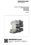
® Power Transmission Installation and Operating Instructions for RINGSPANN Clamping System RTM 608 E 03.639e Schaberweg 30-34 61348 Bad Homburg Germany Telephone +49 6172 275-0 Telefax +49 6172 275-275 www.ringspann.com [email protected] Installation and Operating Instructions for RINGSPANN Clamping System RTM 608 E 03.639e (with RINGSPANN Cone Clamping Element RLK 200) issue: 06.10.2014 Version: 6 drawn: BAHS checked: EISF Pages: 8 Page: 2 IMPORTANT Please read these instructions carefully before installing and operating the product. Your particular attention is drawn to the notes on safety. These installation and operating instructions are valid on condition that the product meets the selection criteria for its proper use. Selection and design of the product is not the subject of these installation and operating instructions. Disregarding or misinterpreting these installation and operating instructions invalidates any product liability or warranty by RINGSPANN; the same applies if the product is taken apart or changed. These installation and operating instructions should be kept in a safe place and should accompany the product if it is passed on to others -either on its own or as part of a machine- to make it accessible to the user. SAFETY NOTICE Installation and operation of this product should only be carried out by skilled personnel. Repairs may only be carried out by the manufacturer or accredited RINGSPANN agents. If a malfunction is indicated, the product or the machine into which it is installed, should be stopped immediately and either RINGSPANN or an accredited RINGSPANN agent should be informed. Switch off the power supply before commencing work on electrical components. Rotating machine elements must be protected by the purchaser to prevent accidental contact. Supplies abroad are subject to the safety laws prevailing in those countries. Installation and Operating Instructions for RINGSPANN Clamping System RTM 608 E 03.639e (with RINGSPANN Cone Clamping Element RLK 200) issue: 06.10.2014 Version: 6 drawn: BAHS Contents 1. General Introduction 2. Design and function 2.1 RLK 608 2.2 Centring bushing with RLK 200 cone clamping element 3. Condition on delivery 4. Installing the RINGSPANN RTM 608 Clamping System 4.1 Mounting the centering bushing on the shaft end 4.1.1 Pre-assembly of the RLK 608 shrink disc 4.1.2 Pre-assembly of the centering bushing on the shaft 4.1.3 Mounting RLK 200 cone clamping element 4.1.4 Mounting RLK 608 shrink disc 4.2 Mounting the motor to the RTM 608 Clamping System 5. Maintenance and dismantling 5.1 Maintenance 5.2 Dismantling the RTM 608 Clamping System 5.2.1 Removing the motor 5.2.2 Dismantling of the RLK 608 shrink disc 5.2.3 Dismantling of the RLK 200 cone clamping element 5.2.4 Dismantling of the centering bushing checked: EISF Pages: 8 Page: 3 Installation and Operating Instructions for RINGSPANN Clamping System RTM 608 E 03.639e (with RINGSPANN Cone Clamping Element RLK 200) issue: 06.10.2014 1. Version: 6 drawn: BAHS checked: EISF Pages: 8 Page: 4 General Introduction The RINGSPANN RTM 608 Clamping System is used to connect an electric motor (with hollowbore rotor) to a shaft. The RTM 608 Clamping System consists of an RLK 608 shrink disc and a centring bushing with a built-in RLK 200 cone clamping element. The RLK 608 shrink disc builds compression between the centring bushing and the shaft, generating torque transmission between the shaft and the electric motor. The centring bushing with RLK 200 supports and stabilizes the motor in order to prevent unacceptable wobbling of the electric motor with torque support during operation. 2. Design and function 2.1 RLK 608: The stepped tapered ring (2) is clamped flush to the stepped tapered bushing (1) with screws (3). The radial forces generated by this configuration ensure friction-tight transmission of power between the shaft and the centring bushing (4). The shrink disc is loosened by loosening the screws (3) and pressed off with the aid of the screws (3). 2.2 Centring bushing with RLK 200 cone clamping element: The centring bushing (4) with RLK 200 (5) centres and supports the electric motor at two points on the shaft. The electric motor is mounted with fastening screws (6) to the centring bushing (4). The RLK 200 cone clamping element (5) prevents rotational bending from producing contact rust at this point. RTM 608- Part number 4224- Design as shown in Fig Clamping screws (3) Distance Min. dist. “Z“ for “B“ for removal of installation screws (3) RLK 608 [mm] [mm] Press-off thread Removal thread „A“ „G“ 050 050000-040230 2.1 8 x M8x20 DIN 933-12.9 11 26 3 x M12 4 x M12 080 080000-060235 2.1 7 26 3 x M12 4 x M12 080 080000-065130 2.1 10 x M10x25 DIN EN ISO 4017-12.9 10 x M10x25 DIN EN ISO 4017-12.9 7 26 3 x M12 4 x M12 Table 2.1 Installation and Operating Instructions for RINGSPANN Clamping System RTM 608 E 03.639e (with RINGSPANN Cone Clamping Element RLK 200) issue: 06.10.2014 Version: 6 drawn: BAHS checked: EISF Pages: 8 Page: 5 Fig. 2.1 3. Condition on delivery The clamping system RTM 608 is delivered as follows: Centering bushing 12 mounting screws supplied loose (6) a loosely enclosed shrink disc RLK 608 a loosely enclosed cone clamping element RLK 200 4. Installing the RINGSPANN RTM 608 Clamping System 4.1 Mounting the centring bushing on the shaft end 4.1.1 Pre-assembly of the RLK 608 shrink disc Grease the seat of the stepped tapered bushing (1) on the centring bushing (4) lightly. Push the RLK 608 shrink disc (1, 2 and 3) onto the centring bushing (4). Do not tighten the screws (3) at this time. 4.1.2 Pre-assembly of the centering bushing on the shaft Push the centring bushing (4) with the RLK 608 shrink disc (1, 2 and 3) onto the end of the shaft. Ensure that the axial distance “Z” (for removal of the screws (3)) from the machine is maintained. Caution! The shaft and the bore in the centring bushing (4) in the vicinity of the stepped tapered ring (1) must be free of grease in order to achieve full torque transmission (computed for a friction coefficient of 0.15). Installation and Operating Instructions for RINGSPANN Clamping System RTM 608 E 03.639e (with RINGSPANN Cone Clamping Element RLK 200) issue: 06.10.2014 Version: 6 drawn: BAHS checked: EISF Pages: 8 Page: 6 4.1.3 Mounting the RLK 200 cone clamping element Apply a light coat of oil to the RLK 200 cone clamping element (5). Do not use grease or oil containing MoS2 or high-pressure additives. Push the RLK 200 cone clamping element (5) into the threaded bore in the centring bushing (4) to the axial stop point. Tighten the clamping screws for the RLK 200 cone clamping element (5) by hand in a crosswise sequence. Tighten the clamping screws for the RLK 200 cone clamping element (5) with a torque spanner to one-half of the torque indicated in Table 2.1 in a crosswise sequence. Tighten the clamping screws for the RLK 200 cone clamping element (5) one by one in a clockwise sequence to one half of the torque indicated in Table 2.1. Tighten the clamping screws for the RLK 200 (5) incrementally one by one in a clockwise sequence until the full torque indicated in Table 2.1 is reached. The tightening procedure is complete when none of the screws can be turned further. RTM 608- Part number 4224- Design as shown in Fig. 050 080 080 050000-040230 080000-060235 080000-065130 2.1 2.1 2.1 Cone Clamping Element RLK 200 (5) dxD [mm] 40 x 65 60 x 90 65 x 95 Clamping screws RLK 200 Tightening Torque for clamping screws RLK 200 M6 M8 M8 16 Nm 36 Nm 36 Nm Table 4.1 4.1.4 Mounting the RLK 608 shrink disc Position the stepped tapered bushing (1) to the position indicated as dimension “B” (Table 2.1). Tighten the clamping screws (3) by hand at first. Turn all screws (3) clockwise (not crosswise) by one-quarter turn each. Please note! When working with shrink discs with slotted stepped tapered bushing, turn the screws to the left and right of the slot one after the other and the other screws uniformly in several increments. aufs führen! Tighten the clamping screws (3) in several successive increments by one-quarter turn each time until the stepped tapered ring (2) and the stepped tapered bushing (1) are flush against the screw-side face (stepped tapered ring and stepped tapered bushing are block tightened. The screws cannot be tightened further). Installation and Operating Instructions for RINGSPANN Clamping System RTM 608 E 03.639e (with RINGSPANN Cone Clamping Element RLK 200) issue: 06.10.2014 Version: 6 drawn: BAHS checked: EISF Pages: 8 Page: 7 Please note! The mounting process is path-controlled. It is not necessary to use a torque spanner. aufs führen! 4.2 Mounting the motor to the RTM 608 Clamping System Push the electric motor with the aid of a lifting device to the axial stop point on the centring ring of the centring bushing (4). Oil the fastening screws (6). Mount the fastening screws (6) and tighten them to the torque indicated in Table 4.2. Ensure that the motor is aligned parallel to the shaft. RTM 608- Part number 4224- Design as shown in Fig. Fastening screws (6) Tightening Torque for fastening screws (6) 050 050000-040230 2.1 123 Nm 080 080000-060235 2.1 080 080000-065130 2.1 12 x M12x30 DIN EN ISO 4762-10.9 12 x M12x30 DIN EN ISO 4762-10.9 12 x M12x30 DIN EN ISO 4762-10.9 123 Nm 123 Nm Table 4.2 5. Maintenance and Dismantling 5.1 Maintenance The RTM 608 Clamping System requires no maintenance as long as it is not disassembled and reinstalled. The following procedures must be performed prior to re-installation: Clean the stepped tapered bushing (1) and the stepped tapered ring (1) after disassembly and lubricate the threads of the screws and the undersurface of the screw heads with a paste containing MoS2 , e. g. „gleitmo 100“ from Fa. FUCHS LUBRITECH (www.fuchs-lubritech.de). Lubricate the tapered surfaces of the cone ring with a thin layer of MoS2 paste „gleitmo 100“ from Fa. FUCHS LUBRITEC ( www. fuchs-lubritec.de) or a molybdenum-sulphide lubricant of equivalent quality. Caution! Use only screws of quality grade 12.9 when replacing clamping screws, otherwise screws may break. Installation and Operating Instructions for RINGSPANN Clamping System RTM 608 E 03.639e (with RINGSPANN Cone Clamping Element RLK 200) issue: 06.10.2014 Version: 6 drawn: BAHS checked: EISF Pages: 8 Page: 8 5.2 Dismantling the RTM 608 Clamping System 5.2.1 Removing the motor Loosen the fastening screws (6). Pull the electric motor off of the RTM 608 Clamping System. Use press-off threading “A” (see Fig. 2.1 and Table 2.1) to facilitate the procedure if necessary. 5.2.2 Dismantling the RLK 608 shrink disc Loosen the clamping screws (3) one by one in several increments of one-quarter turn each. This helps prevent screw breakage and clamping surface tilting. Caution! Do no turn screws completely out of the threaded bore, as this will pose the danger of accidents. If the rings (1 and 2) are not loosened automatically, - loosen the same number of screws (3) as press-off threadings and - turn them into the press-off theadings of the stepped tapered bushing (1) and - then turn them into the press-off threadings uniformly until the stepped tapered ring (2) is forced off of the stepped tapered bushing. 5.2.3 Dismantling the RLK 200 cone clamping element Normally, the RLK 200 cone clamping element will be released automatically when the clamping screws are loosened incrementally in a crosswise sequence. Loosen the clamping screws incrementally in a crosswise sequence. pounding lightly on the clamping screws with an soft face hammer. Remove the RLK 200 cone clamping element and set it to the side. 5.2.4 Dismantling the centring bushing Pull the centring bushing (4) off of the shaft. Use press-off threading “G” (see Fig. 2.1 and Table 2.1) to facilitate the procedure if necessary.