1
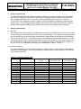
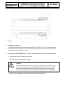
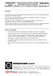
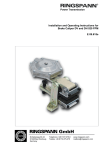
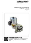
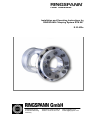
® Power Transmission Installation and Operating Instructions for RINGSPANN Clamping System RTM 607 E 03.632e Schaberweg 30-34 61348 Bad Homburg Germany Telephone +49 6172 275-0 Telefax +49 6172 275-275 www.ringspann.com [email protected] Installation and Operating Instructions for RINGSPANN Clamping System RTM 607 (and Cone Clamping Element RLK 607) issue: 03.06.2014 Version :11 drawn: Su checked: Su E 03.632e Pages: 8 Page: 2 IMPORTANT Please read these instructions carefully before installing and operating the product. Your particular attention is drawn to the notes on safety. These installation and operating instructions are valid on condition that the product meets the selection criteria for its proper use. Selection and design of the product is not the subject of these installation and operating instructions. Disregarding or misinterpreting these installation and operating instructions invalidates any product liability or warranty by RINGSPANN; the same applies if the product is taken apart or changed. These installation and operating instructions should be kept in a safe place and should accompany the product if it is passed on to others -either on its own or as part of a machine- to make it accessible to the user. SAFETY NOTICE Installation and operation of this product should only be carried out by skilled personnel. Repairs may only be carried out by the manufacturer or accredited RINGSPANN agents. If a malfunction is indicated, the product or the machine into which it is installed, should be stopped immediately and either RINGSPANN or an accredited RINGSPANN agent should be informed. Switch off the power supply before commencing work on electrical components. Rotating machine elements must be protected by the purchaser to prevent accidental contact. Supplies abroad are subject to the safety laws prevailing in those countries. Installation and Operating Instructions for RINGSPANN Clamping System RTM 607 (and Cone Clamping Element RLK 607) issue: 03.06.2014 Version :11 drawn: Su checked: Su E 03.632e Pages: 8 Page: 3 Contents 1. General Introduction 2. Design and function / Parts list 2.1 RLK 607 2.2 Centering bushing 3. Condition on delivery 4. Installing the RINGSPANN Cone Clamping Element RLK 607 and the centering bushing 5. Maintenance and dismantling Installation and Operating Instructions for RINGSPANN Clamping System RTM 607 (and Cone Clamping Element RLK 607) issue: 03.06.2014 1. Version :11 drawn: Su checked: Su E 03.632e Pages: 8 Page: 4 General Introduction The RINGSPANN RTM 607 clamping system is used to connect an electric motor (with hollowbore rotor) to a shaft or hollow shaft. The RTM 607 clamping system consists of an RLK 607 cone clamping element ( pos. 1 to 6) and a centring bushing (pos.7) see fig. 2.1 and 2.2. The RLK 607 cone clamping element supports torque transmission between the shaft and the electric motor. The centring bushing supports the motor on side facing the RLK 607 in order to prevent unacceptable wobbling of the electric motor with torque support during operation. 2. Design and function 2.1 RLK 607 The multiple-slot cone bushing (1) is affixed with screws (4) to the hollow-bore rotor of the motor. The cone ring (2) is fitted with screws (3) to the cone bushing (1). The radial forces generated by this configuration ensure friction-tight transmission of power between the shaft (or hollow shaft) and the cone bushing (1). The clamp connection is released by loosening the screws (3). In the event that the cone ring (2) does not separate from the cone bushing (1), the cone ring (2) can be released with the aid of the screws (5). The constructive design of the RLK 607 is shown in Fig. 2.1 or Fig. 2.2, depending upon the type, as indicated in Table 2.1 and 2.2. 2.2 Centering bushing The centring bushing (7) centres and supports the electric motor on the left-hand side towards the shaft (or hollow shaft). The centring bushing is axially fixed by a step (diameter 153) and the cone clamping element. Table 2.1 Clamping System RTM RTM 607- Part number 60/153g7 65/153g7 70/153g7 75/153g7 80/153g7 90/153g7 100/153g7 110/153g7 125/153g7 180/153g7 200/153g7 220/153g7 4220-060000-… 4220-065000-… 4220-0700004220-075000-… 4220-080000-… 4220-090000-… 4220-100000-… 4200-110000-… 4220-125000-… 4220-180000-… 4220-200000-… 4220-220000-… Design as shown in Fig. 2.1 2.1 2.1 2.1 2.1 2.1 2.1 2.2 2.2 2.2 2.2 2.2 Tightening torque for screws (3) 84 Nm 84 Nm 84 Nm 84 Nm 84 Nm 84 Nm 84 Nm 123 Nm 123 Nm 123 Nm 123 Nm 123 Nm Tightening torque for screws (4) 84 Nm 84 Nm 84 Nm 84 Nm 84 Nm 84 Nm 84 Nm 84 Nm 84 Nm 84 Nm 84 Nm 84 Nm Installation and Operating Instructions for RINGSPANN Clamping System RTM 607 (and Cone Clamping Element RLK 607) issue: 03.06.2014 Version :11 drawn: Su checked: Su E 03.632e Pages: 8 Page: 5 Table 2.2 Cone Clampimg Element RLK RLK 60760/153g7 65/153g7 70/153g7 75/153g7 80/153g7 85/153g7 90/153g7 100/153g7 105/153g7 110/153g7 125/153g7 135/153g7 Fig. 2.1 Part number 4200-060707-… 4200-065707-… 4200-070707-… 4200-075707-… 4200-080707-… 4200-085707-… 4200-090707-… 4200-100707-… 4200-105707-… 4200-110707-… 4200-125707-… 4200-135707-… Design as shown in Fig. 2.1 2.1 2.1 2.1 2.1 2.1 2.1 2.1 2.1 2.2 2.2 2.2 Tightening torque for screws (3) 84 Nm 84 Nm 84 Nm 84 Nm 84 Nm 84 Nm 84 Nm 84 Nm 84 Nm 123 Nm 123 Nm 123 Nm Tightening torque for screws (4) 84 Nm 84 Nm 84 Nm 84 Nm 84 Nm 84 Nm 84 Nm 84 Nm 84 Nm 84 Nm 84 Nm 84 Nm Installation and Operating Instructions for RINGSPANN Clamping System RTM 607 (and Cone Clamping Element RLK 607) issue: 03.06.2014 Version :11 drawn: Su checked: Su E 03.632e Pages: 8 Page: 6 Fig. 2.2 3. Condition on delivery The RTM 607 clamping systemis delivered as shown in Fig. 2.1 or Fig. 2.2. represented with centring bushing. On supplies of the Cone Clamping Element RLK 607 the centring bushing does not belong to the scope of supply. 4. Installing the RINGSPANN RLK 607 Cone Clamping Element and the centring bushing Remove the screws (3) and lay them aside. Pull off the cone ring (2) and lay it aside. Caution! Please ensure that the cone ring (2) and the cone bushing (1) are oiled only. friction-reducing lubricants for example with MoS2 may not be used, as such lubricants can seep through the slots in the cone bushing (1) into the gap between the shaft and the cone bushing (1) and reduce torque transmission. Push the centring bushing (7) into the bored hole in the electric motor. Installation and Operating Instructions for RINGSPANN Clamping System RTM 607 (and Cone Clamping Element RLK 607) issue: 03.06.2014 Version :11 drawn: Su checked: Su E 03.632e Pages: 8 Page: 7 Attach the cone bushing (1) to the rotor with the screws (4). Tighten the screws with a torque spanner to the torque indicated in Table 2.1. Please note! A hole ( 10.5 mm) has been bored through the diameter of the cone bushing (1). The unit comprising the cone bushing and the motor rotor can be secured in proper alignment using this hole and a suitable tool (pin wrench). Push the cone ring (2) onto the cone bushing (1) and turn the screws (3) to the point at which a gap of 1 ... 3 mm remains between the screw heads and the cone ring (2). Make sure that the cone ring (2) sits loosely on the cone bushing and does not exert clamping pressure on it. Install the electric motor with the RLK 607 cone clamping element and centring bushing at the prescribed position on the shaft (or hollow shaft). Now clamp the cone ring (2) tightly to the cone bushing (1) with the screws (3). Tighten all screws crosswise by hand at first (torque approx. ca. 5 ... 8 Nm). Check for concentric run between the shaft and the motor. Radial run-out deviation can be corrected by tightening the screws (3) accordingly. Please note! Excessive tightening of one of the screws (3) “lifts“ the electric motor away from the shaft at that point. aufs führ aufs führen Tighten the screws (3) one by one in clockwise manner with a torque spanner. Each screw may be tightened by no more than a quarter turn at once. Repeat this procedure with the torque spanner set at the torque value indicated in Table 2.1 until none of the screws turns. Check for concentric run between the shaft and the electric motor. If radial run-out deviation is excessive, loosen the screws (3) and repeat the tightening procedure, checking concentric run frequently as tightening progresses and correcting deviations by tightening the screws (3) accordingly. Please note! Excessive tightening of one of the screws (3) “lifts“ the electric motor away from the shaft at that point. If you get no good result by doing this, you have to ensure that the motor is centered to the shaft before tightening the screws (3). Installation and Operating Instructions for RINGSPANN Clamping System RTM 607 (and Cone Clamping Element RLK 607) issue: 03.06.2014 Version :11 drawn: Su checked: Su E 03.632e Pages: 8 Page: 8 Caution! After installation, inspect the gap between the cone bushing (1) and the cone ring (2). The gap must measure at least 0.1 mm around the entire circumference (and between the cone bushing and the mounting screws (5) as well). If this minimum gap is not maintained, the RLK 607 clamping element may not not perform ist function reliably! Possible causes of insufficient gap include: insufficient shaft or hollow shaft diameter, insufficient hollow shaft wall thickness (resulting in excessive deformation of the hollow shaft). 5. Maintenance and dismantling The RLK 607 cone clamping element and the centring bushing are maintenance-free components. If the cone ring (2) does not separate from the cone bushing (1) after removing the screws (3) during dismantling of the RLK cone clamping element, please proceed as follows: Loosen the nuts (6) and turn them until they touch the head of the screws (5). Tighten the screws (5) until they touch the cone bushing. Tighten the screws (5) one by one in increments of one quarter turn until the cone ring (2) is released.