1
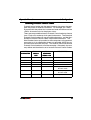
CL4xxe-2A Printers
Operation Manual
Issued December 2000
SATO Group of Companies
www.satoworldwide.com
SATO INTERNATIONAL PTE LTD
SATO EUROPE NV
438A Alexandra Road #05-01/ 02,
Leuvensesteenweg 369,
Alexandra Technopark,
1932 Sint-Stevens-Woluwe, Brussels,
Singapore 119967
Belgium
Tel: 65-6271-2122
Tel: 32 (0)-2-788-80-00
Fax: 65-6271-2151
Fax: 32 (0)-2-788-80-80
Email: [email protected]
Email: [email protected]
SATO UK LTD
SATO DEUTSCHLAND GMBH
Valley Road, Harwich, Essex England
Schaberweg 28, 61348
Co12 4RR, United Kingdom
Bad Homburg, Germany
Tel: 44-1255-240000
Tel: 49 (0)-6-1726-8180
Fax: 44-1255-240111
Fax: 49 (0)-6-1726-818-199
Email: [email protected]
Email: [email protected]
SATO POLSKA SP Z O.O.
SATO FRANCE S.A.
Ul Okolna 2, 50-422 Wroclaw
Parc d'activités - rue Jacques Messager
Poland
59175 TEMPLEMARS, France
Tel: 48-71-335-23-20
Tel: +33 (0)3 20 62 96 40
Fax: 48-71-335-23-25
Fax: +33 (0)3 20 62 96 55
Email: [email protected]
Email: [email protected]
SATO AMERICA INC.
SATO ASIA PACIFIC PTE LTD
10350 Nations Ford Road Suite A,
438A Alexandra Road #05-01/02,
Charlotte, NC 28273, USA
Alexandra Technopark, Singapore 119967
Tel: 1-704-644-1650
Tel: 65-6271-5300
Fax: 1-704-644-1662
Fax: 65-6273-6011
Email: [email protected]
Email: [email protected]
Warning: This equipment complies with the requirements in Part 15 of FCC rules for a
Class A computing device. Operation of this equipment in a residential area may cause
unacceptable interference to radio and television reception requiring the operator to take
whatever steps necessary to correct the interference.
All rights reserved. This document, nor any part of it, may be reproduced or issued to
third parties in any form without the express permission of SATO Europe. The material in
this document is provided for general information only and is subject to change without
notice. SATO Europe does not assume responsibility for any errors or omissions.
Warning
It is essential that the safety and operating procedures contained
within this manual be brought to the attention of, and are used by,
all personnel likely to operate this printer/product.
This printer/product must only be used for the purpose for which it
was designed.
This is a Class A product. In a domestic environment this product
may cause radio interference in which case the user may be
required to take adequate measures.
Electrostatic discharges on the connector pins and on the memory
card may damage the printer.
In the case of fire, water must not be used on the product to extinguish the fire, and the appropriate type of fire extinguisher should
be readily available.
No modifications, either mechanical or electrical, should be made
to this printer/product or accessory without the written consent of
SATO Europe N.V. Any modifications made without this consent
may invalidate guarantee claims.
Other manuals relating to this printer include additional information
relating to other aspects of the safe operation of the printer, and are
available from your SATO supplier.
All consumable waste, such as the label backing paper and used
carbon ribbon must be disposed of carefully, and in a manner that
will cause the minimum of environmental pollution.
Should you have any doubts regarding the setting, operating or any
safety aspects of this printer/product, please contact your SATO
supplier.
SATO Europe N.V. makes no guarantee that all the features
described in this manual are available in all models, and, due to
SATO’s policy of continuous development and improvement, specifications are liable to change, without notice.
Consumables
Always use SATO carbon ribbons or equivalent. The use of incorrect materials may cause malfunctions of the printer and void the
warranty.
Conventions
Text that appears bold italic and all in capitals such as LABEL
refers to a key or an LED on the operation panel.
Text that appears enclosed in brackets such as <ESC> refers to an
Escape sequence of a data string.
Text that appears bold italic such as On-Line refers to a function or
to a result.
Text that appears in bold such as VR1 refers to electrical components like pins, resistors connectors and so on.
Warranty and Copyright
SATO Europe N.V. makes no guarantee of any kind with regard to
this material, including, but not limited to, the implied guaranties of
merchantability and fitness for a particular purpose.
SATO Europe N.V. shall not be liable for errors contained herein or
for any incidental consequential damages in connection with the
furnishing, performance, or use of this material.
This document contains proprietary information which is protected
by copyright.
All rights are reserved.
No part of this document may be reproduced or issued to third parties in any form whatsoever without the express permission of
SATO Europe N.V.
The information in this document is subject to change without
notice.
© Copyright 2000 SATO Europe N.V.
Contents
1. Specifications ................................................................................. 1
2. Introduction .................................................................................... 3
2.1
Installation Considerations ................................................. 3
2.2
Ribbon ................................................................................ 3
2.3
Dimensions ......................................................................... 4
2.4
Component Designations ................................................... 5
2.5
Interface Connections, Input And Output Panel ................. 6
2.6
Switches And Sensors ........................................................ 7
2.7
Computer Connections ..................................................... 10
2.7.1 Bi-directional parallel interface ............................... 10
2.7.2 Optional interface (RS232C) ...................................11
2.7.3 Optional Interface (USB) ........................................ 12
2.7.4 Optional Interface (LAN) ......................................... 12
3. Printer Configuration .................................................................... 13
3.1
DIP Switch Settings .......................................................... 13
3.1.1 RS232 Transmit/Receive Setting ........................... 14
3.1.2 External Connector PIN Assignments .................... 21
3.1.3 External Output Signal Types ................................. 23
3.2
Default Settings ................................................................ 24
3.3
Printer Adjustments .......................................................... 25
3.3.1 Normal Mode .......................................................... 25
3.3.2 User Mode .............................................................. 25
3.3.3 Print Darkness Setting ............................................ 26
3.3.4 Print Speed Adjustment .......................................... 26
3.3.5 Pitch Offset and Direction ....................................... 27
3.3.6 Cancel print Job ..................................................... 27
3.3.7 Advanced Settings ................................................. 28
4. Media Loading ............................................................................. 29
4.1
Loading Labels ................................................................. 29
4.1.1 Label rolls ............................................................... 29
4.1.2 Fanfold Labels ........................................................ 33
4.2
Loading the Ribbon .......................................................... 37
i
5. Troubleshooting ........................................................................... 41
5.1
Print Quality Problems ...................................................... 41
6. Cleaning and Maintenance .......................................................... 45
6.1
Cleaning the Print Head .................................................... 46
6.1.1 Cleaning the Print Head using Print Head Cleaner 46
6.1.2 Cleaning the Print Head using the Lapping Film .... 47
6.2
Cleaning the Platen and Rollers ....................................... 48
Appendix A Advanced Settings ......................................................... 49
Appendix B Declaration of Conformity .............................................. 53
ii
Operation Manual
1.
1. Specifications
Specifications
The major difference in the CL408e
e and the CL412e
e printers is the
resolution of the head. The CL408e
e with its 203 dpi head provides
an economical labeling solution for most applications. The CL412e
e
provides a higher print resolution, 305 dpi, to give laser quality
printing. It is useful when higher resolution is needed for detailed
graphic images.
CL408e
CL412e
Print Type
Direct Thermal, Thermal Transfer
Resolution
0,125 mm (8dot/mm, 203dpi)
0,083 mm (12dot/mm, 305dpi)
Speed
User selectable from 50 mm/sec to
150 mm/sec
User selectable from 50 mm/sec to
100 mm/sec
Darkness
5 steps; selectable by printer driver (<ESC> code) or via display
Print Area
Pitch
178mm
356mm
1249mm
Width
104mm
104mm
104mm
Standard
<AX>
Option <EX>
Pitch
178mm
356mm
830mm
Width
104mm
104mm
104mm
Standard
<AX>
Option <EX>
Media Width
22~128 mm (25~131 mm incl. Backing paper)
Media Length
and Calliper
Batch:
Dispense:
Cutter:
Tear-Off:
Label Roll
Maximum Roll Diameter: 220 mm (face in)
Label Inner Core Diameter: 38-76 mm
Media Types
Die-cut label; Continuous Material; Tag Material, Roll Type - face-in, Fan-Fold
Type, Fabric.
Carbon Ribbon
450 metre long, face in, I.D. 25,4 mm, thickness: 4.5 micron, black and
coloured
Bar-Codes
UPC A/E; EAN 8 & 13; Code 39; Code 128; UCC/EAN 128; Interleaved 2 of 5;
Industrial 2 of 5; Matrix 2 of 5; NM-7; MSI; Bookland; Postnet
06~178
17~178
17~178
17~178
(09~181
(18~181
(18~181
(18~181
mm
mm
mm
mm
incl.
incl.
incl.
incl.
backing
backing
backing
backing
paper)
paper)
paper)
paper)
0,08~0,21
0,08~0,18
0,08~0,21
0,08~0,21
mm
mm
mm
mm
Bar-Code Ratios 1:2, 1:3, 2:5
Bar-Code Sizes
Height: 4 dots to 600 dots; width – user definable
Rotational
Capability
90° steps
2-D Codes
Data Matrix, Maxicode, PDF 417, QR-Code
CL408e
CL408e/412e
/412e
1
1. Specifications
Operation Manual
Fonts
U; S; M; WB; WL; XU; XS; XM; XB; XL; OCR-A/B; Outline Font (50-999)
Rasterizer Font Triumvirate & Times (08 – 99 points or 16 – 999 dots)
Label Sensing
Reflective Sensor (eye-mark) bottom reading, movable
See-through Sensor (Gap), movable
CPU
32 bit SH3 RISC Processor/ 117MHz
Memory
Capacity
16MB SDRAM; 2,9MB Input Buffer; 2MB Flash Memory Intern (standard)
Memory Expansion Optional - Internal: 4MB Flash Memory SIM Card
- External: up to 4MB S-RAM Card or up to 16MB Flash Card
Interfaces
ECP Parallel (IEEE 1284)
Centronics Parallel
RS232C Standard (2400 – 19.200 Baud)
RS232C Highspeed (9600 – 57.600 Baud)
USB (12Mbit/s)
LAN (TCP/IP protocol 10/100 Base T)
Twinax/Coax
RS422 / 485
Front Panel
Operation Switches
Setting Switches
LED
LCD
Dimensions
Height: 324,9 mm Width: 278 mm Depth: 429,4 mm
Weight
13 kg (standard)
Power
110 - 240V +/- 10%, 50/60 Hz, 130W
Environmental
Conditions
Operating: +5 ~ +40°C, humidity 30 ~ 80% RH non-condensing
Storage:
-5 ~ +60°C, humidity 30 ~ 90% RH non-condensing
Approvals
Options
2
Online Key, Feed Key
2 x Dip-Switches
Status
Menu Controlled Printer Configuration and Error Messages
Supported Languages:
English (default), German, French, Spanish, Italian,
Portuguese
UL, CSA, TÜV-GS, CE
Guillotine Cutter, Dispenser with Internal Backing Paper Rewinder,
External Label Rewinder R400, Memory Expansion, Smart Keyboard
CL408e
CL408e/412e
/412e
Operation Manual
2.
2. Introduction
Introduction
The SATO CL408e/412e Printer Operation Manual provides information for installing and maintaining the SATO CL408e/412e printers. Step-by-step maintenance instructions are included in this
manual with typical problems and solutions. It is recommended
that you become familiar with each section in this manual before
installing and maintaining the printer. This manual is divided into
the following six sections:
• Chapter 1 - Specification
• Chapter 2 - Introduction
• Chapter 3 - Printer Configuration
• Chapter 4 - Media Loading
• Chapter 5 - Troubleshooting
• Chapter 6 - Cleaning and Maintenance
• Appendix
2.1 Installation Considerations
Printer operation can be affected by the printer environment. The
location of the printer should be free from dust, humidity, and sudden vibrations. To obtain optimum results from the printer, avoid
locations influenced by:
• Direct or bright sunlight since bright light will make the label sensor less responsive and may cause the label to be sensed incorrectly.
• Warm temperatures which can cause electrical problems within
the printer.
2.2 Ribbon
Use only SATO thermal transfer ribbons which were formulated
expressly for use in all SATO printers. Use of other than approved
ribbons may result in unsatisfactory print quality and/or damage to
the print head and may void your warranty.
CL408e/412e
3
2. Introduction
Operation Manual
2.3 Dimensions
Width
278 mm
Depth
429.4 mm
Height
324.9 mm
Depth
Width
Height
4
CL408e/412e
Operation Manual
2. Introduction
2.4 Component Designations
OPERATION PANEL
DISPLAY
OPTIONAL
CUTTER
ASSEMBLY
RIBBON REWIND
SHAFT
RIBBON UNWIND
SHAFT
DIP SWITCH
CONFIGURATION
TABLE
PRINT HEAD
MAIN PC BOARD
PLATEN ROLLER
KB PC BOARD
POWER
SUPPLY UNIT
TIMING
BELTS
STEPPER MOTOR
CL408e/412e
5
2. Introduction
Operation Manual
2.5 Interface Connections, Input And Output Panel
FRONT OF UNIT
ELECTRONICS SIDE: Contains Main Logic Power
Supply, Stepper Motor, Main Circuit Board.
DISPLAY
PANEL
OPERATION
PANEL
MEDIA
OUTPUT
REAR OF UNIT
6
MECHANICAL SIDE
CONTAINS RIBBON,
MEDIA, SENSORS
Boards are supplied with the following connectors:
PARALLEL
PARALL EL CONNECTOR:
For printer using parallel
communication connection.
RS232 CONNECTOR:
For printer using serial
communication connection.
TWINAX/COAX, USB, LAN:
For printer operating in a
mini/mainframe/network
environment.
MEMORY CARD SLOT:
Optional connectors for use
with PCMCIA Memory Card.
EXT. CONNECTOR:
This is an external signal
connector.
POWER ON/OFF SWITCH:
To turn power On or Off
AC FUSE:
To protect the machine from
abnormal power input. Type
3A/250V
AC INPUT CONNECTOR:
To input 220V 50/60 Hz. Use
power cable provided.
CL408e/412e
Operation Manual
2. Introduction
2.6 Switches And Sensors
COVER OPEN SENSOR: When this
sensor is activated, the printer will not
and Cover Open message will be displayed
on display panel.
HEAD OPEN LEVER: When the print head is opened, this
switch is activated and the printer will stop printing or is
not ready to print.
INTERLOCK TAB: The front cover is fitted with a micro switch.
When the cover is opened, the cover open sensor is activated
and the printer will stop printing or is not ready to print.
CL408e/412e
7
2. Introduction
Operation Manual
RIBBON SENSOR: This sensor is a motion detector that
signals the printer when the ribbon supply is turning. This
sensor is used for both the ribbon end and ribbon near end
(approximately 45 feet) sensing.
LABEL SENSOR: Both the “I”-mark (reflective) and
Gap(transmissive) sensors on the CL408/412 can be adjuste
over a limited range. They are both located in the label
sensor unit. The assembly can be adjusted by loosening the
green sensor adjust knob located underneath the label
transport assembly and sliding the label sensor unit to the
desired position. The gap sensor can be adjusted from a
minimum of 0.67 in (17mm) to a maximum of 2.5 in. (64 mm)
and the “I”-mark from a minimum of 0.25 in. (6 mm) to a
maximum of 2.1 in. (53 mm) from the fixed position, “inside
label guide”.
Sensor unit
SENSOR
ADJUST
KNOB
I-mark
8
Gap
CL408e/412e
Operation Manual
2. Introduction
FEED Key: Momentary switch. Pressing
this key feeds one blank label through the
printer when it is off-line. When the printer
is on-line, another copy of the last label will
be printed if “Reprint w\Feed is selected in
The printer menu.
L INE Key: Momentary switch. Pressing
this key toggles the printer between the online and off-line mode. When the printer is
on-line, it is ready to receive data from the
host. This key acts as a pause during a
print job by taking the printer off-line. It can
also be used as a pause function key to
stop the printer during the printing process.
PITCH Potentiometer: Adjusts home
position of the label(+/- 3.75mm).
Affects stop position of label feed, print
position, and dispense position.
Larger adjustments should be made
using the Pitch Offset function.
Function Indicator: When Cutter
or Dispenser is used.
OFFSET Potentiometer: To adjust back/forward
feed for dispenser (+/- 3.75mm).
PRINT Potentiometer: To adjust print darkness (fine adjustment).
DSW2 & 3: DIP Switches to set operational parameters of printer.
NOTE: Optional RS232 Communication Card contains DSW1
switches which are configured when supplied with the printer.
Status LED
OFF:
Green:
Flashing Green:
Orange:
Red:
CL408e/412e
Offline
Online
Data receiving or input buffer near full
Data compiling
Error condition
9
2. Introduction
Operation Manual
2.7 Computer Connections
2.7.1 Bi-directional parallel interface
1. Turn off the power of the printer. Using an interface cable connect the computer to the bi-directional parallel interface connector at the rear panel of the printer.
2. Be sure to use a IEEE1284 compatible cable.
Connector: 36 PIN Amp
Max. Cable length: 1,8 m Centronic
5 m IEEE1284
Wire Connection Table for IEEE1284 compatible cable:
Host
1
2
3
4
5
6
7
8
9
10
11
12
13
10
Printer
1
D0
2
D1
3
D2
4
D3
5
D4
6
D5
7
D6
8
D7
9
AKN
10
Busy
11
PE
12
Select
13
Strobe
Host
14
15
16
17
18
19
20
21
22
23
24
25
Shield
LF
Error
Init
Select in
GND
GND
GND
GND
GND
GND
GND
GND
Printer
14
32
31
36
33
19
21
23
25
27
29
30
Shield
CL408e/412e
Operation Manual
2. Introduction
2.7.2 Optional interface (RS232C)
Connecting the printer to your computer.
1. Turn off the power of the printer. Using an interface cable connect the computer to the optional interface connector at the rear
panel of the printer.
2. Interface Cable
The wire connection varies depending on the communication
product.
Prepare an appropriate cable for the communication protocol.
Connector: DSUB-25S.
Cable length: Less than 5 meters.
ER Control
1
1
2
2
3
3
4
4
5
5
6
6
7
7
20
20
CL408e/412e
Status 3/4
1
1
2
2
3
3
4
4
5
5
6
6
7
7
20
20
11
2. Introduction
Operation Manual
2.7.3 Optional Interface (USB)
Connecting the printer to your computer.
1. Turn off the power of the printer. Using an interface cable connect the computer to the optional interface connector at the rear
panel of the printer.
2. Interface Cable
USB connector for a printer is specified as a Type B Receptacle.
Please use a Type B cable when you connect it with the printer.
2.7.4 Optional Interface (LAN)
Connecting the printer to a network.
1. Turn off the power of the printer. Using an interface cable connect the computer to the optional interface connector at the rear
panel of the printer.
2. Interface Cable
Please use a cross-cable when you connect one printer to one
computer. If you connect a printer to a HUB, please use a
straight cable.
12
CL408e/412e
Operation Manual
3.
3. Configuration
Printer Configuration
3.1 DIP Switch Settings
Two DIP switches DSW2 and DSW3 are located under the front
door panel and a DSW1 switch is located on an optional RS232
serial interface board.
These switches can be used to set:
• RS232C transmit/receive parameters
• Thermal transfer or direct thermal mode
• Label sensor enable/disable
• Head check mode
• Hex dump mode
• Receive buffer size
• Operation mode
DIP Switch Panel Layout for DSW1
Located on RS232 Interface Board
To set the switches, first power the unit Off, then position the DIP
switches. After placing the switches in the desired positions, power
the printer back on. The switch settings are read by the printer electronics during the power up sequence. They will not become effective until the power is cycled.
CL408e
CL408e/412e
/412e
13
3. Configuration
Operation Manual
3.1.1 RS232 Transmit/Receive Setting
Data Bit Selection (DSW1-1)
This switch sets the printer to receive either 7 or 8 bit data bits for
each byte transmitted.
DSW1-1
SETTING
*OFF
8 Data Bits
ON
7 Data Bits
DSW1
ON
OFF
1
2
3
4
5
6
7
8
Parity Selection (DSW1-2, DSW1-3)
These switches select the type of parity used for error detection.
DSW1DSW1-2 DSW1DSW1-3 SETTING
DSW1
*OFF
*OFF
No Parity
OFF
ON
Even
ON
ON
OFF
Odd
OFF
ON
ON
Not Used
1
2
3
4
5
6
7
8
Stop Bit Selection (DSW1-4)
Selects the number of stop bits to end each byte.
DSW1
DSW1-4
SETTING
*OFF
1 Stop Bit
ON
2 Stop Bits
ON
OFF
1
2
3
4
5
6
7
5
6
8
Baud Rate Selection (DSW1-5, DSW1-6)
Selects the data rate(bps) for the RS232 port.
DSW1
DSW1DSW1-5
DSW1DSW1-6
SETTING
*OFF
*OFF
9600
ON
OFF
OFF
ON
19200
ON
OFF
38400
ON
ON
57600
1
2
3
4
7
8
* Factory Default
14
CL408e
CL408e/412e
/412e
Operation Manual
3. Configuration
Communication Protocol Selection (DSW1-7, DSW1-8)
Selects the flow control and status reporting.
DSW1DSW1-7
DSW1DSW1-8
SETTING
*OFF
*OFF
Rdy/Bsy
OFF
ON
Xon/XOff
ON
OFF
Status 3
ON
ON
Status 4
DSW1
ON
OFF
1
Note:
2
3
4
5
6
7
8
For Status 4 the DSW2-8 must be set to OFF
Print Mode Selection (DSW2-1)
Selects between direct thermal printing on thermally sensitive
paper and thermal transfer printing using a ribbon.
DSW2
DSW2-1
SETTING
*OFF
Therm Trans
ON
Direct Therm
ON
OFF
1
2
3
4
5
6
7
8
Sensor Type Selection (DSW2-2)
Selects type of sensing.
DSW2-2
SETTING
*OFF
Gap
ON
“I” Mark
DSW2
ON
OFF
1
2
3
4
5
6
7
8
Head Check Selection (DSW2-3)
When selected, the printer will check for head elements that are
electrically malfunctioned.
DSW2
DSW2DSW2-3
SETTING
*OFF
Disabled
ON
ON
Enabled
OFF
1
2
3
4
5
6
7
8
* Factory Default
CL408e
CL408e/412e
/412e
15
3. Configuration
Operation Manual
Hex Dump Selection (DSW2-4)
Enables Hex Dump mode.
DSW2
DSW2DSW2-4
SETTING
*OFF
Disabled
ON
ON
Enabled
OFF
1
2
3
4
5
6
7
8
Receive Buffer Selection (DSW2-5)
Selects the operating mode of the receive buffer.
DSW2
DSW2-5 SETTING
OFF
Single Job
*ON
Multi Job
ON
OFF
1
2
3
4
5
6
7
8
6
7
8
Download Mode (DSW2-6)
For Firmware Download.
DSW2
DSW2DSW2-6
SETTING
*OFF
Disabled
ON
Enabled
ON
OFF
1
2
3
4
5
Protocol Control Code Selection (DSW2-7)
Selects the command codes used for protocol control.
DSW2
DSW2DSW2-7 SETTING
*OFF
Standard
ON
Non-Std.
ON
OFF
1
2
3
4
5
6
7
8
* Factory Default
16
CL408e
CL408e/412e
/412e
Operation Manual
3. Configuration
Selecting Protocol Control Codes
Protocol control codes are the special control characters that prepare the printer to receive instructions. For example, the <ESC>
character tells the printer that a command code will follow and the
<ENQ> character asks for the printer status.
There are two pre-defined sets of Protocol Control codes to choose
from. Each set is made up of six special characters. The Standard
Protocol Control codes are non-printable characters, and the NonStandard Protocol Control codes are printable characters. The
Non-Standard set may be useful on host computers using protocol
converters or in an application where non-printable ASCII characters cannot be sent from the host. This manual uses the Standard
Protocol Control codes for all of the examples. Alternately, the user
may define and download a set of custom Protocol Control Codes.
CONTROL
CHARACTER
STANDARD
DSW2-7
OFF
NONSTANDARD
DSW2-7 ON
DESCRIPTION
STX
02 Hex
7B Hex = {
Start of Data
ETX
03 Hex
7D Hex = }
End of Data
ESC
1B Hex
5E Hex = ^
Command code to follow
Null
00 Hex
7E Hex = ~
Cutter command
ENQ
05 Hex
40 Hex = @
Get printer status,
Bi-Com mode
Can
18 Hex
21 Hex = !
Cancel print job,
Bi Com mode
Off-Line
40 Hex
5D Hex = ]
Take printer Off-Line
CL408e
CL408e/412e
/412e
17
3. Configuration
Operation Manual
Compatibility Mode Selection (DSW2-8)
Software command compatibility with earlier SATO model printers.
DSW2
DSW2DSW2-8
SETTING
*OFF
Status 4
ON
ON
OFF
Compatibility
1
2
3
4
5
6
7
8
Mode Selection (DSW3-1 and DSW3-2)
Selects the operating mode of the printer.
DSW3DSW3-1 DSW3DSW3-2
*OFF
DSW3
SETTING
*OFF Batch/Continuous
OFF
ON
Tear Off
ON
OFF
Cutter
ON
ON
Dispenser
ON
OFF
1
2
3
4
5
6
7
8
Label Sensor Selection (DSW3-3)
Enables or disables the Label Sensor. If the Sensor is enabled, it
will detect the edge of the label and position it automatically. If it is
disabled, the positioning must be under software control using Line
Feed commands.
DSW3
DSW3DSW3-3
SETTING
*OFF
Sensor Used
ON
ON
Sensor Not Used
OFF
1
2
3
4
5
6
7
8
* Factory Default
18
CL408e
CL408e/412e
/412e
Operation Manual
3. Configuration
Back Feed Selection (DSW3-4)
When Back-Feed is enabled, the printer will position the label for
dispensing/cutting and retract it to the correct print position before
printing the next label.
DSW3
DSW3-4
SETTING
*OFF
Enabled
ON
Disabled
ON
OFF
1
2
3
4
5
6
7
8
Note:
Back Feed function only works, if Tear Off, Cutter or Dispenser is selected. See DSW3-1, 3-2.
External Signal Interface
The EXT connector on the CL printer rear panel is intended for use
with the external printer accessories such as label rewinders or
applicators. The 14-pin Centronics type connector provides a
choice of four different output signals along with various error conditions.
Print Start Signal Selection (DSW3-5)
DSW3
DSW3DSW3-5 SETTING
*OFF
Disabled
ON
ON
Enabled
OFF
1
(Output on Pin 5)
2
3
4
5
6
7
8
External Signal Type Selection (DSW3-6, DSW3-7)
Both the polarity and signal type (level or pulse) of the external print
synchronizing signal can be selected.
DSW3
DSW3DSW3-6 DSW3DSW3-7 SETTING
*Off
*Off
Type 4
ON
Off
On
Type 3
OFF
On
Off
Type 2
On
1
2
3
4
5
6
7
8
On
Type 1
(Output on Pin 6)
* Factory Default
CL408e
CL408e/412e
/412e
19
3. Configuration
Operation Manual
Repeat Print via External Signal (DSW3-8)
Allows the applicator to reprint the current label in the print buffer.
DSW3
DSW3DSW3-8
SETTING
SETTING
*OFF
Disabled
ON
Enabled
ON
(Output on Pin 7)
OFF
1
2
3
4
5
6
7
8
Note:
The DIP Switch functions listed incorporate the latest
firmware revisions at the time of printing.
* Factory Default.
20
CL408e
CL408e/412e
/412e
Operation Manual
3. Configuration
3.1.2 External Connector PIN Assignments
PIN
DIRECTION
1
To Host
2
Reference
3
To Host
Ribbon Out - This pin goes low when the ribbon is out.
4
To Host
Error - This pin goes low when the printer detects an
error condition such as head open or receiving buffer
full.
5
To Printer
Print Start - The printer will print one label when this
pin is pulled to ground. This signal must be enabled
by placing switch DSW3-5 on the Control Panel in the
OFF position.
6
To Host
End Print - It is used to drive an applicator or other
external device requiring synchronization with the print
cycle. You may choose between four types of output
signals using control panel DSW3-6 and DSW3-7 selections.
7
To Printer
Print Repeat - The printer repeatedly prints the current
label in the print buffer immediately after receiving this
signal.
DSW3-8 must be ON.
8
To Printer
Vcc - +5V
9
To Host
On-Line
10
To Host
Ribbon Near End
11
To Printer
12
To Host
+24V - Used to power accessory items.
13
To Host
Vcc - +5V
14
Reference
CL408e
CL408e/412e
/412e
SIGNAL DESCRIPTION
Label Out - This pin goes low (0V) when a label out
error exists.
Signal Ground
TBD
Frame Ground
21
3. Configuration
NOTE:
22
Operation Manual
The signals on pins 1, 3, 4 and 6 each have an open collector output. These pins normally measure +.07V maximum when a true condition exists. If a false condition
occurs, the voltage will drop to 0V. To achieve a signal
level of +5V, you must add a 1K ohm, ¼ W pull-up resistor
between the open collector output pin and Vcc (pin 13)
as illustrated. This will provide a signal level of +5V for a
true condition and 0V when a false condition exists. The
maximum voltage that can be applied to these pins is
+50V and the maximum current they can sink is 500 milliamps.
CL408e
CL408e/412e
/412e
Operation Manual
3. Configuration
3.1.3 External Output Signal Types
Pin 13
Vcc = +5V
1 K ohm, ¼W
Signal Out
Pin 1, 3 4 or 6
+5V
TYPE 1
0V
20 milliseconds
+5V
TYPE 2
0V
+5V
TYPE 3
0V
+5V
TYPE 4
0V
Start Print
(Label Feed
Stop)
CL408e
CL408e/412e
/412e
End Print
(Label Feed
Stop)
23
3. Configuration
Operation Manual
3.2 Default Settings
Switch Selections
All switches except DSW 2-5 are placed in the OFF position
(default) for shipping. This will result in the following operating configuration:
• Communications: 8 data bits, no parity, 1 Stop bit, 9600 Baud
• Protocol:
Ready/Busy
• Sensor:
Gap Sensor
• Receive Buffer:
Multi Job
• Mode:
Batch/continuous
• Pitch:
Sensor Used
• Back feed:
Enabled
• External Signals: Disabled
Software Default Settings
The CL408e
e/412e
e stores the software settings upon receipt and
uses them until they are again changed by receipt of a command
containing a new setting. These settings are stored in non-volatile
RAM and are not affected by powering the printer off. The printer
may be reset to use the default software settings by depressing the
LINE and FEED keys simultaneously while powering the printer on.
This will result in the following default configuration:
• Print Darkness:
"3"
• Print Speed:
4 inches per second
• Print Reference:
Vertical = 0001, Horizontal = 0001
• Zero:
Slash
• Auto On Line:
Enabled
• Ignore CR/LF:
Disabled
• Character Pitch:
Proportional
• Cover Open Sensor: Enabled
• Auto Online Feed:
Disabled
• Feed On Error:
Disabled
• Repeat Print:
Enabled
• Forward/Backfeed:
Standard
• Select Language:
English
• Priority Setting:
LCD
24
CL408e
CL408e/412e
/412e
Operation Manual
3. Configuration
3.3 Printer Adjustments
The LCD Panel on the CL408e
e/412e
e printer is used in conjunction
with the LINE and FEED switches by the operator to manually enter
printer configuration settings. Many of the settings can also be controlled via software commands and in the case of conflict between
software and control panel settings, the printer will always use the
last valid setting. If you load a label job that includes software settings and then enter a new setting via the operation panel, the manually set values will be used by the printer. If you set the values
manually and then download a job with software settings, the software settings will be used.
3.3.1 Normal Mode
When the printer is powered on, the readout should display the following message.
ONLINE
QTY:000000
The LCD Panel will display the ONLINE status on the top line of the
display and the bottom line will contain the label quantity (QTY) status. The ONLINE message will be changed to OFFLINE whenever
the printer is switched OFFLINE by depressing the LINE key. As
soon as a print job is received, the QTY message will indicate the
number of labels to be printed. As soon as the label job begins to
print, the display will indicate the number of labels remaining in the
print job to be printed.
3.3.2 User Mode
1. The printer is first taken OFFLINE by pressing the LINE key
once. The display will change to:
OFFLINE
QTY:000000
2. When the display changes to OFFLINE, press the FEED and
LINE keys simultaneously for more than one second. The
printer now displays the first USER mode adjustment (Print
Darkness).
CL408e
CL408e/412e
/412e
25
3. Configuration
Operation Manual
3.3.3 Print Darkness Setting
There are five PRINT DARKNESS (or heat range) settings on the
CL408e
e/412e
e. The higher numbers represent darker settings. The
current setting is indicated by a blinking curser on one of the range
settings.
To change the setting perform the following steps:
1. Use the LINE key to step the blinking
cursor to the desired setting.
PRINT DARKNESS
12345
2. Once the correct setting is selected,
press the FEED key to accept the setting and advance to the
next adjustment.
Note:
This setting can be overridden by software.
3.3.4 Print Speed Adjustment
There are five PRINT SPEED settings on the CL408e
e/412e
e. The
setting is listed on the bottom line of the display. The current setting
is indicated by a blinking curser on one of the speed settings.
To change the setting perform the following steps:
1. Use the LINE key to step the blinking
cursor to the desired setting.
PRINT SPEED
23456
2. Once the correct setting is selected,
press the FEED key to accept the setting and advance to the
next adjustment.
Note:
26
This setting can be overridden by software.
CL408e
CL408e/412e
/412e
Operation Manual
3. Configuration
3.3.5 Pitch Offset and Direction
The label pitch is the distance from the leading edge (the edge that
comes out of the printer first) of a label and the leading edge of the
next label. The leading edge position of the label can be adjusted
relative to the print head +/- 49 mm in increments of 1 mm using
the following procedure. Once the position is set, it can be adjusted
+/- 3.75 mm using the PITCH potentiometer on the adjustment
panel.
MOVED WITH MINUS(-)
OFFSET
ORIGINAL PRINT LINE
MOVED WITH
POSITIVE(+) OFFSET
LINE FEED
DIRECTION
To change the setting perform the following steps:
1. Use the LINE key to step the counter to the desired position.
The display will increment one step for each time the LINE key
is pressed. If the LINE key is pressed continuosly the reading
will advance to a setting of 49 mm after which it will automatically
wrap and start with "00" again. The pitch direction set in the previous step will be displayed in front of the Offset setting.
PITCH OFFSET
+00mm
2. Once the setting is correct, press the FEED key to accept the
setting and advance to the CANCEL PRINT job display.
3. You may wish to check your settings by printing a test label after
you have completed the adjustments to ensure that they are correct.
3.3.6 Cancel print Job
If the printer has a print job(s) loaded in memory, selecting YES will
cause the job(s) to be cleared. The default selection is NO. Make
CL408e
CL408e/412e
/412e
27
3. Configuration
Operation Manual
sure that you want to cancel the print job before selecting YES as
the job cannot be recovered and will have to be retransmitted to the
printer.
To cancel the print perform the following steps:
1. Use the LINE key to step the blinking cursor to either YES or NO.
CANCEL PRINT JOB
NO
YES
2. Once the correct setting is selected, press the FEED key to
accept the setting and terminate the user mode of operation and
return you to the normal mode ONLINE display.
If you wish to change any of the settings, you must first set the
printer to OFFLINE and enter the user mode again by simultaneously pressing FEED and LINE keys for more than one second.
3.3.7 Advanced Settings
See Appendix A for advanced settings.
Please not that you will need special instructions for some of these
settings!
28
CL408e
CL408e/412e
/412e
Operation Manual
4.
4. Media Loading
Media Loading
4.1 Loading Labels
4.1.1 Label rolls
1. First, open the top cover by swinging it up and then open the
front door by pressing the green lever downwards.
G reen lever
2. Open the print head assembly by turning the head latch toward
the rear of the printer. The print head assembly is spring-loaded
and will automatically open as soon as the head latch is disengaged.
CL408e
CL408e/412e
/412e
29
4. Media Loading
Operation Manual
3. Push the label unwind guide to the outside of the printer to give
the maximum label width.
Label roll
Label unw ind guide
4. Load the media roll onto the label unwind bracket so that the
printing side of the labels faces upwards as it unwinds from the
roll. Push the roll all the way to the inside of the printer and push
the label unwind guide snugly against the outside of the label
roll.
30
CL408e
CL408e/412e
/412e
Operation Manual
4. Media Loading
5. Feed the labels under the label guide shaft, through the print
head assembly and out of the front of the printer.
Label
guide shaft
Note:
CL408e
CL408e/412e
/412e
When the label dispenser option has been installed,
remove 600 to 800 mm of labels from the backing and
feed the backing back through the label dispense path.
31
4. Media Loading
Operation Manual
6. Inspect the label route and check that the path matches that
illustrated in the label loading diagram. Set the adjustable label
guides to keep the labels against the backplate of the printer.
Note:
The following step is not for Thermal direct.
7. If the ribbon is already loaded, close the print head assembly by
pushing downward the head latch until it latches closed.
If the ribbon is not loaded, see the description for loading ribbons
on page 47.
H ead
latch
32
CL408e
CL408e/412e
/412e
Operation Manual
4. Media Loading
8. Close the front door and the top cover.
4.1.2 Fanfold Labels
1. Open the top cover by swinging it up and then the front door by
pressing the green lever downwards. Remove the cover plate
from the rear panel.
CL408e
CL408e/412e
/412e
33
4. Media Loading
Operation Manual
2. Open the print head assembly by turning the head latch toward
the rear of the printer. The print head assembly is spring-loaded
and will automatically open as soon as the head latch is disengaged.
3. Lay the fanfold labels behind the printer and feed them through
the slot and over the label unwind bracket. The printing side of
the labels has to show upwards. Push the label unwind guide
snugly against the outside of the fanfold label.
Fanfold labels
Label unw ind guide
34
CL408e
CL408e/412e
/412e
Operation Manual
4. Media Loading
4. Feed the labels under the label guide shaft, through the print
head assembly and out of the front of the printer.
Label guide shaft
5. Inspect the label route and check that the path matches that
illustrated in the label loading diagram. Set the adjustable label
guides to keep the labels against the backplate of the printer.
CL408e
CL408e/412e
/412e
35
4. Media Loading
Operation Manual
6. If the ribbon is already loaded, close the print head assembly by
pushing downward the head latch until it latches closed.
If the ribbon is not loaded, see the following description in chapter 4.2 Loading the ribbon.
7. Close the front door and the top cover.
36
CL408e
CL408e/412e
/412e
Operation Manual
4. Media Loading
4.2 Loading the Ribbon
1. Open the top cover by swinging it up and the front door by pressing the green lever downwards.
G reen lever
2. Open the print head assembly by turning the head latch toward
the rear of the printer. The print head assembly is spring-loaded
and will automatically open as soon as the head latch is disengaged.
CL408e
CL408e/412e
/412e
37
4. Media Loading
Operation Manual
3. Load the ribbon onto the ribbon unwind spindle, pushing it all the
way to the inside of the spindle. The side of the ribbon carrying
the carbon ink must be inwards while unwinding the carbon ribbon roll counter-clockwise.
4. Place the core on the ribbon rewind spindle, pushing it all the
way to the inside of the spindle. Note that the empty core of each
subsequent roll becomes the next rewind core.
38
CL408e
CL408e/412e
/412e
Operation Manual
4. Media Loading
5. Feed the leader portion of the ribbon through the print head
assembly and up to the ribbon rewind spindle and tape it to the
ribbon core. Manually turn the rewind spindle to wrap the ribbon
onto the core making one to two turns to secure it.
6. Make sure the ribbon path matches the one shown in the diagram.
CL408e
CL408e/412e
/412e
39
4. Media Loading
Operation Manual
7. If the labels or tags are already loaded, close the print head
assembly by pushing downward on the green tab until it latches
closed.
H ead latch
8. Close the front door and the top cover.
Note:
40
Run a test print to ensure that the labels and ribbons are
loaded correctly.
CL408e
CL408e/412e
/412e
Operation Manual
5.
5. Troubleshooting
Troubleshooting
The design of the SATO CL-408e
e/412e
e printer is based upon
proven technology and reliable components. When a problem
occurs, the solution can be easily traced using the troubleshooting
tables in this section. This table list symptoms, probable causes,
and suggested corrective actions.
Both print quality and general operational problems are listed in the
troubleshooting table.
5.1 Print Quality Problems
Symptom
Probable Cause
Image Voids Poor quality labels
Ribbon
Wrinkle
Suggested Corrective Action
Use thermal transfer compatible
stock
Poor quality ribbons
Use genuine SATO ribbons
Ribbon not matched to label
stock
Check with media suppliers
Select better suited carbon ribbon
Contact your local dealer
Damaged electronics
Replace circuit board
Damaged Platen
Replace Platen
Poor Head Alignment
Adjust head balance
Adjust ribbon roller
Adjust head alignment
Poor Ribbon Tension
Adjust ribbon tension
Worn Platen
Replace platen
Foreign material on head or
platen
Clean head and platen
Foreign materials on labels
Use high quality label stock
Damaged print head
Replace print head
CL408e
CL408e/412e
/412e
41
5. Troubleshooting
Light
Images
Smearing
Operation Manual
Poor quality labels
Use thermal transfer compatible
stock
Poor quality ribbons
Use genuine SATO ribbons
Low print head energy/darkness
Adjust darkness control
Low print head pressure
Use correct head pressure position
Ribbon not matched to label
stock
Select better suited carbon ribbon
Contact your local dealer
Low ribbon drive torque
No ribbon movement
Adjust ribbon drive clutch
Foreign material on head
Clean head and platen
Poor head alignment
Align Print Head
Excessive print speed
Reduce print speed setting
Poor quality labels
Select better suited carbon Ribbon
Poor quality ribbons
Use genuine SATO ribbons
Foreign material on head/pla- Clean head and platen
ten
No Ribbon
Movement
42
Foreign material on labels
Use high quality label stock
Excessive print head energy
Adjust darkness control
Excessive print speed
Adjust print speed
Excessive head pressure
Use correct head pressure position
Incorrect ribbon core size
Use genuine SATO ribbons
Loose drive clutch
Adjust clutch tension
Loose platen drive belt
Adjust/replace belt
No + 24 volt output
Test power supply and replace if
required
Loose service screws on
rewind pulley
Tighten service screws
Damaged electronics
Replace circuit board
CL408e
CL408e/412e
/412e
Operation Manual
No Label
Movement
5. Troubleshooting
Loose/broken platen drive belt Adjust/replace belt
Incorrect label pitch sensor
selected
Select correct label sensor type
(DSW2-2)
No +24 volt output
Test power supply and replace if
required
Loose set screw on platen pul- Tighten set screws
ley/stepper motor
No Printed
Image
Print head not connected
Verify print head connector fully
seated at head and main PCB
Ribbon upside down
Use genuine SATO ribbons
No + 24 volt output
Test power supply and replace if
required
Damaged print head
Replace print head
Damaged electronics
Replace circuit board
Back light
but no
words on
display or
no display.
Most common failure of printer Verify that the cable and connector are properly seated
is DOA situation
The most likely cause is the
ribbon cable is disconnected
or not connected firmly
POWER
AC power cable not connected Verify that the cable is connected to the printer and the AC
outlet
HEAD
OPEN
Main Power Fuse defective
Replace fuse
Defective power supply
Test power supply and replace if
defective
Head not locked
Close and latch head release
CL408e
CL408e/412e
/412e
43
5. Troubleshooting
LABEL
END
Label supply roll empty
Operation Manual
Replenish label supply
Label stock not routed through Reload labels correctly
sensor
Label sensor not positioned
correctly
Adjust sensor position
Label sensor blocked
Clean label sensor
Incorrect label sense threshold setting
Adjust label sense threshold
Platen drive malfunction
See Service Manual
Ribbon supply roll empty
Replenish ribbon supply
Ribbon sensor out of alignment
Realign ribbon sensor
Ribbon sensor blocked
Clean ribbon sensor
No cardboard core on ribbon
rewind
Use cardboard core on ribbon
rewind
SENSOR
ERROR**
Auto Treshold not in range
Check label path, sensor position and DIP switch setting
No Label
Drive
Timing Belt bad/loose
Replace/tighten timing belts
RIBBON
END
Note:
44
This error condition is stored in the printer memory. To
reset this error it is necessary to open the print head
while printer power is ON.
CL408e
CL408e/412e
/412e
Operation Manual
6.
6. Cleaning and Maintenance
Cleaning and Maintenance
Proper handling
The print head contains a precise printing surface that must be
carefully protected from mechanical damage. Extreme care must
be exercised during handling and installation to prevent scratching,
chipping, denting or otherwise damaging the exposed surface.
Cleaning
Only solvent, i.e. alcohol and other cleaning methods recommended by SATO should be used to periodically remove paper residue from the print head. Apply carefully with a cotton swab.
Frequency of cleaning depends upon paper type and mechanical
factors and should be completed at each ribbon change. Only clean
when the printer is switched off and cooled to room temperature to
avoid thermal shock damage.
Do not operate the machine immediatly after cleaning to ensure the
head is totally dry of any cleaning fluids.
Do not use abrasive materials in cleaning. However, SEG supplies
a special lapping film, SEG-No. 1938, to clean the print head surface.
CL408e
CL408e/412e
/412e
45
6. Cleaning and Maintenance
Operation Manual
6.1 Cleaning the Print Head
6.1.1 Cleaning the Print Head using Print Head Cleaner
1. Switch off the power to the printer.
2. Open the top cover and the front door.
3. Open the print head assembly by turning the head latch toward
the rear of the printer. The print head assembly is spring-loaded
and will automatically open as soon as the head latch is disengaged.
4. Apply any SATO approved thermal print head cleaner to a cotton
swab.
5. The print head faces downward along the front edge of the
assembly. Pass the end of the dampened swab along the entire
width of the print head. (You may need to move the ribbon out of
the way to do this.)
6. Check for any black colouring or adhesive on the swab after
cleaning.
7. Repeat as necessary until the swab stays clean, after being
passed over the head.
8. The head should be cleaned at least every time the ribbon is
changed and more often in dusty environments.
46
CL408e
CL408e/412e
/412e
Operation Manual
6. Cleaning and Maintenance
6.1.2 Cleaning the Print Head using the Lapping Film
1. Cut the lapping film with a pair of scissors or a sharp knife to
120mm width.
2. Switch off the power to the printer.
3. Place the lapping film between print head and platen with the
abrasive side face-up. Close the print head with the head latch.
4. Pull the cleaning film by hand slowly toward the front of the
printer.
5. Repeat steps 3 and 4 two or three times.
6. Finally, clean the print head with a print head cleaner as
described previously.
CL408e
CL408e/412e
/412e
47
6. Cleaning and Maintenance
Operation Manual
6.2 Cleaning the Platen and Rollers
1. Switch off the power to the printer.
2. Open the top cover and the front door.
3. Open the print head assembly by pushing the head latch toward
the rear of the printer. The print head assembly is spring-loaded
and will automatically open as soon as the head latch is disengaged.
4. Apply any SATO approved cleaner to a clean wipe.
5. The platen is the rubber roller directly below the print head. It
should be cleaned of any ribbon or label residue.
6. The label unwind guides used in guiding the labels through the
printer must be cleaned of any label or ribbon residue or other
foreign material.
7. Repeat as necessary. The platen and rollers should be cleaned
whenever foreign matter such as dust or adhesive is present.
48
CL408e
CL408e/412e
/412e
Operation Manual
Appendix A
Appendix A Advanced Settings
CL408e
CL408e/412e
/412e
49
Appendix A
50
Operation Manual
CL408e
CL408e/412e
/412e
Operation Manual
CL408e
CL408e/412e
/412e
Appendix A
51
Appendix A
Operation Manual
This page is intentionally left blank.
52
CL408e
CL408e/412e
/412e