1
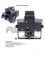
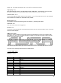
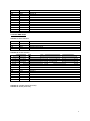
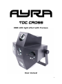
DMX LED light effect with 5 lenses
User manual
1
Safety precautions
WARNING: This unit may cause serious injury to the eyes when used incorrectly. It is therefore
strongly advised to read this user manual carefully, to get familiance yourself with the functions of this
device.
WARNING: This unit must be operated by, or under the supervision of an adult. This device is not
suitable for children.
WARNING: Do not look directly into the beam from a short distance. This may cause serious injury to
the eyes. Ayra is not responsible for any injuries caused by incorrect use of this device.
Installation requirements:
- Always check the power supply to which you want to connect the device. If the voltage requirements
do not meet, do not connect the device as this may cause serious damage.
- This device must be installed by a professional technician, in a standing or hanging position. Only
use the included mounting bracket if you want to position the unit against a ceiling or truss system.
- When installed in a hanging position above your audience, this unit MUST be secured by using a
safety cable, capable of holding 10x the weight of this device.
- The unit is designed to be installed with a halfcoupler or G-clamp, by using the included mounting
bracket. Direct installation with proper bolts is also possible.
- Make sure there are no flammable objects in the direct environment of the device.
- Do not block the beam-exit.
- Keep a minimum distance of 0.25 meter from any walls to provide sufficient cooling.
- Make sure the beam-exit is not blocked by any objects in the near environment.
- Always use the included power supply. Contact your local dealer for a replacement unit if necessary.
Maintenance and protection
- Keep the unit away from dusty environments, as this may have negative effects on the ventilation
and optics. Clean the optics with a small, soft brush and vacuum cleaner when needed. Clean the
housing of the unit with a damp cloth. WARNING: Always disconnect the unit from the power supply
when cleaning the unit. Reconnect the unit only when any moist on the fixture has evaporated
completely.
- Do not switch the power on and off frequently, as this may cause serious damage to the unit.
- Avoid heavy shocks and collision during transport and use, as this may cause damage to the LED
light source, electronic circuit, optics and housing.
- Keep the device away from moisture, rain, water or any liquids as this may cause a short circuit
and/or electric shocks. If any liquid enters the unit, power supply or housing of the unit, disconnect the
unit immediately and do not reconnect the power supply. Contact your local dealer or technician to
inspect the unit for any damage.
2
Box contents
Box contents
1x TDC Cross fixture
1x power cable
Unit and accessory inspection
- Always use the supplied power cable to connect the unit to a power supply. If the cable appears
broken or has visible damage, do not use it.
- If the unit is not going to be used for a longer period of time, disconnect it from the power supply and
store it in a dust-free environment.
- Always check the unit for possible damage before use. If you suspect that something is wrong with
the unit, do not connect it to a power source! When you suspect that your unit is broken or damaged,
contact your local dealer or a certified technician to inspect the unit.
- When your device does not generate any light, do not look directly into the lens. When the fixture
suddenly produces a beam, it may cause injury to your eyes.
3
Device overview
1. Beam output
2. Adjustable bracket
3. IEC Power inlet with integrated fuse holder
4. Control panel display with MENU, UP and DOWN buttons
5. Built-in microphone for sound active mode
6. DMX input (3P XLR)
7. DMX output (3P XLR)
4
Setting up the unit
To activate the unit, connect the included power supply with the unit and a suitable 230V, 50 Hz power
outlet. The unit will activate directly after it is plugged in to a wall outlet or other power source.
The status of the fixture is shown on the display. Certain values determine the current status and will
change when you push buttons on the control panel. The buttons each have their own function, for
easy navigation in the control panel. When connecting the unit for the first time,
Press the ‘MENU’ button to switch modes, so you can easily select the built-in master/slave, music
controlled or DMX mode. Press ‘Enter’ to confirm a setting.
Display codes:
DMX-Mode: Addr / 1 :
This value represents the DMX channel where the scanner is currently set to. 1 stands for channel 1,
but can be changed with the UP and DOWN buttons to a value from 1 to 255.
When receiving DMX data, a small red dot on the display will blink continuously, regardless of what
function is being used.
Music controlled mode: Soun:
When no DMX-signal is detected in DMX-mode, or when you select the master-mode, the unit will turn
itself into music controlled mode, displaying ‘Soun’. Use the microphone sensitivity potentiometer to
adjust the sensitivity of the internal microphone for optimal light to sound functionality. When no music
is detected, the scanner will play a slow automatic program until a beat or loud sound is detected. The
Sound mode can be activated or de-activated.
Master/Slave mode: Nast / SL 1 / SL 2:
The ‘Nast’ value stands for the master-unit, which will use the internal microphone to perform musiccontrolled. This fixture will send out a signal for slave fixtures, which you may connect using standard
XLR male to XLR female cables (not included).
The slave units show ‘SL 1’ or ‘SL 2’ on the display. This way you can select a synchronous or
horizontal mirrored slave-function, for more dynamic effects.
Stand-alone mode: Shnd:
This mode uses the internal programs of the unit to perform a stand-alone light show. The TDC Cross
has 13 built-in programs, varying from 0 to 12. When the internal microphone is active, the unit will
change the beam output on every detected beat. When there is no music detected, the unit will
provide a steady and slow change of patterns.
When the internal microphone is not active, the unit will play the programs on a predefined speed.
Microphone sensitivity: Sens
The microphone sensitivity is digitally adjustable between 0 and 100. 0 is a very low sensitivity, 100 is
a very high sensitivity. Feel free to adjust this sensitivity until you have reached the optimal setting.
LED display mode: Led:
The LED display of the unit can be turned off during use, which makes your light-show more attractive,
especially if the display is visible for your audience. When using the menu-buttons the display will be
lit, but after several seconds inactivity the display will be turned off. When pressing one of the menu
buttons the display will activate itself again. The off value means display OFF, the on value means
5
display ON. The DMX indicating dot will not turn off for convenience reasons.
Flip display: Disp
When activating this function, the LED display will flip upside-down. This might be convenient when
the fixture is installed in a certain way and you need to read the values on the display.
Channel mode: Chnd
This mode changes the DMX channel mode between 1 and 4. Each mode has its own characteristics,
which makes basic, medium or advanced control possible.
Working time: hour:
It is possible to see the total working time of this fixture, by activating this feature.
Test mode: test:
The unit will test all its internal programs.
Version: Vers
This feature is only intended for technical purposes and shows the current firmware version of the unit.
This can not be changed.
DMX control mode:
This fixture can be controlled using a DMX-controller and standard XLR male to XLR female cable.
When doing so, make sure your DMX-controller is capable of controlling your fixture. When in doubt,
contact your local dealer for advice.
Set the correct address on the digital display, you are able to choose a value between 001 and 255.
When a DMX-signal is received, a blinking red dot on the display is active.
NOTE: At some point, mirror-motors and lenses will be identified by using the numbers 1, 2, 3 and 4.
The numbers apply from left to right. The most left mirror is mirror 1, the most right mirror is mirror 4.
This unit has the following DMX-channels and DMX-values:
1 channel DMX mode
Channel 1: Pattern
Start value
0
8
18
28
38
47
57
67
76
86
96
105
115
125
End value
7
17
27
37
46
56
66
75
85
95
104
114
124
133
Function
Blackout
Chase 1
Chase 2
Chase 3
Chase 4
Chase 5
Chase 6
Chase 7
Chase 8
Chase 9
Chase 10
Chase 11
Chase 12
Chase 13
6
134
144
154
163
173
183
192
202
212
221
231
241
250
143
153
162
172
182
191
201
211
220
230
240
249
255
Chase 14
Chase 15
Chase 16
Chase 17
Chase 18
Chase 19
Chase 20
Chase 21
Chase 22
Chase 23
Chase 24
Chase 25
Random
4 channel DMX mode
Channel 1: Mode selection
Start value
0
10
130
250
End value
9
129
249
255
Function
Off
Synchronous show
Asynchronous show
Sound active
Channel 2: Chase selection
Start value
0
22
43
64
86
107
128
107
128
150
171
192
214
235
End value
21
42
63
85
106
127
149
127
149
170
191
213
234
255
Function
Chase 1
Chase 2
Chase 3
Chase 4
Chase 5
Chase 6
Chase 7
Chase 8
Chase 9
Chase 10
Chase 11
Chase 12
Chase 13
Chase 14
Channel 3: Variable speed (slow-fast)
Channel 4: Strobe (slow-fast)
7
Installation and maintenance
Mounting the bracket
A pre-mounted hanging bracket is provided, with screwknobs at both sides of the fixture. This bracket
can be used to install the unit to a fixed structure, such as a T-bar or truss.
Installing the scanner in a hanging position
When you wish to hang the scanner against a wall, ceiling or beam, make sure to use proper
installation tools and let a skilled technician install the scanner for you.
When you wish to install the scanner to a lighting stand or truss system, use a G-clamp or halfcoupler
for optimal, safe and stable fixation. Check the technical specifications of your light stand or truss
system to gather more information on maximal loads and other safety precautions.
Transport
When using this fixture in mobile setups, provide sufficient protection during transport. Use the original
packaging of this unit, or use a professional flightcase with proper foam inlay. This way the electronics,
optics and housing are protected against severe shocks, exterior damage and failing electronics.
Replacing the internal fuse
First check whether a failing power supply may be the cause of malfunction. When you suspect that
the internal fuse is broken, the fuse can be replaced by removing the fuse cover, located directly below
the power inlet.
WARNING: Before changing the fuse, always disconnect the fixture from your wall outlet or any other
power supply to prevent electric shocks.
Always replace a broken fuse with a fuse that has the same type and rating. After the fuse has been
replaced, always close the fuse-cover. Reconnect the fixture to your power supply and check whether
the problem is solved. When this does not solve your problem, contact your local dealer for help.
Spare parts
This unit has no user serviceable parts inside. When any damage to internal components occur,
contact your local dealer or a specialized technician in order to repair the fixture.
Cleaning:
Clean the housing of the fixture frequently with a damp cloth, to remove dust and/or dirt. WARNING:
Always disconnect the fixture from your wall outlet or other power supply and let the fixture dry before
reconnecting it. This prevents possible electrical shocks.
The lenses can be cleaned with a non-aggressive glass cleaning solution, but is not recommended.
Ayra recommends to clean the mirror and lens with a fine brush, while removing dust and/or dirt with a
vacuum cleaner. Avoid touching the lenses with your bare fingers, to prevent fingerprints on the optics.
Checkup
To prevent dangerous situations, make sure your fixture is in optimal condition before using it. Check
your fixture frequently by using the following checklist:
- All screws must be mounted tightly.
- Check all screws and metal parts for corrosion. No visible corrosion may be present.
- The exterior of your fixture must be in optimal condition. Check your fixture for dents, cracks or
missing parts.
- Your installation spot must be in optimal condition. Check your installation spot for corrosion, cracks,
dents and strength.
8
- Electrical components (connectors and cables) must be in optimal condition. Any form of damage
(cuts, exposed wire cores or any other visual deformities should not be present.
If any visual or mechanical damage is detected, contact your local dealer or a specialized technician.
Do not use a damaged or failing fixture.
Connectors and wiring schematics:
DMX-connections:
Electrical wiring:
9
Technical specifications
-
LED light effect with 5 lenses
Light source: 320 LEDs (80 red, 80 green, 80 blue, 40 white, 40 amber
1 or 4 DMX-channels
3-pin XLR in- and output
Music controlled mode with internal microphone
Microphone sensitivity adjustable through menu
Working modes: music controlled, DMX, automatic, test, master/slave
Power consumption: 40 Watt
Fuse: T6.3A 250V 20mm glass fast blow
Power supply: 230V AC, 50 Hz
Measurements: 457 x 433 x 286 mm (with bracket)
Weight: 4 kg
Connectors:
- DMX: 3p XLR male and female
- Power: IEC power connector
Included accessories:
- Power cable with Shucko & IEC connectors
10