1
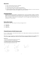
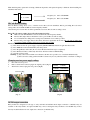
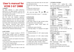
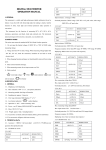
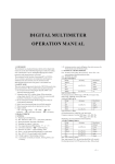
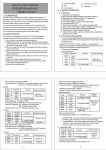
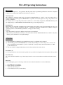
F24 -60 Operating Instructions
Warranty
Lee’s Hi-Tech Enterprises Co., Ltd. guarantees that this product meets its published specifications at the time of shipment
from the factory. Under proper installation it should work as expected.
Warranty Period
This equipment is warranted against defects in material and manufacturing for a period of one year from the date of
shipment. During the warranty period, TELECRANE is responsible for necessary repairs as long as the product can be
proved to be defective.
For warranty service or repair this product must be returned to a service facility designated by TELECRANE. Buyer will
pay shipping charges to TELECRANE while TELECRANE will pay return shipping charges.
Excluded Items
This warranty does not include consumptive parts such as batteries, fuses, buttons, relays. Also this warranty does not cover
damages caused by improper installation, improper or insufficient maintenance, unauthorized modification, improper
operation, ignorance of environmental specifications, or improper software setting.
Remarks
No other warranty is expressed or implied, except for the above mentioned.
The remedies provided herein are the buyer’s sole and exclusive remedies. TELECRANE shall not be liable for any direct,
indirect, special, incidental or consequential damages.
Attention
Never dismantle the equipment by any unauthorized personnel, or equipment may be damaged.
After finishing operation of TELECRANE radio controller shut off main power to the crane, power to receiver, and
remove transmitter key. If transmitter’s power is controlled by “rotary key switch”, then need turn the key to “OFF”
position and remove it.
The crane should be equipped with main power relay, limit switch and other safety devices.
Precautions ( I )
To avoid any interference, the receiver must be placed as far as possible from frequency inverter and power cable as possible.
Precaution ( II )
The receiver should be installed on top of the electrical control box. Do not mount the receiver inside the electrical control
box.
Emergency
In case of Emergency, please follow the procedure below and contact the distributor for service immediately.
1.
2.
3.
4.
Press EMS button of transmitter.
Remove the key from transmitter.
Switch off crane main power.
Contact distributor nearest you immediately.
How to start
1.
2.
3.
4.
5.
Insert 4 AA-size batteries into battery compartment.
Insert rotary key and switch to ON position.
Follow the Power-On procedure to energize receiver main relay.
Operate normally according to the function settings have been done.
Follow the instructions below to switch off the system: (1) Press EMS button /mushroom, (2) remove the key and
keep it in safe place, (3) Switch off the equipment’s main power (e.g. Crane)
Transmitter Batteries
Transmitter requires 4 AA size alkaline or rechargeable batteries. 3 stages power indicator available on transmitter.
During operation, green LED indicator flashes when battery power is full and flashes yellow when battery power is low.
Replace new battery immediately when yellow indicator appears, unloading and stop all activity until new battery is
replaced. An EMS stop signal will be sent automatically to receiver accompany with red LED indicator if the
transmitter power is below the limit.
Receiver Power Supply
Each transformer provide 2 option voltages for receiver power supply as below
(1)
(2)
(3)
(4)
48/110 VAC
110/220 VAC
48/220 VAC
220/380 VAC
Changing Frequency & identify frequency quartz
It’s easy to change frequency of new F24-60. The frequency can be changed simply by replacing correspondent frequency
quartz into both TX and RX.
Note: There are 2 types of frequency are available: VHF and UHF. Do not replace the VHF quartz unit into UHF transmitter
or receiver. The UHF and VHF frequency band can be found on both TX and RX RF module with a check mark “v”.
Instructions:
(1). Pry up the existing quartz unit with a flat screwdriver
(2). Remove the quartz unit from the RF module.
(3). Straight up both pins of the new quartz unit with pliers.
(4). Insert new quartz unit vertically into the RF module.
(5). Press the new quartz down into the socket.
1
2
4
5
3
1
Note: Each frequency quartz unit is having 2 different frequencies. The quartz frequency is different when installing into
transmitter and receiver.
T : 321.00 MHz
R : 331.70 MHz
Frequency for
TX is 321.00 MHz
Frequency for
RX is 331.70 MHz
ID Code Remote Setting
ID Code Remote setting allows you to overwrite receiver ID code from transmitter. Before performing ID code remote
setting, make sure both TX and RX are in same frequency channel.
Caution: The prior receiver ID code will be permanent erased once ID code remote setting is done.
Before ID code remote setting, please follow the instruction below,
Make sure both TX and RX are same model and in the same frequency channel.
Receiver JP1 jumper must be installed in order to perform ID code remote setting.
To avoid interference during remote setting, have transmitter closer to RX as possible.
Receiver AC power supply must be disconnect and turn on again after 20 seconds. (ID code remote setting must
be completed within 4 minutes after receiver is being turn on again).
Instructions:
(1) Disconnect receiver AC power supply completely (MAIN SWITCH) and turn on again after 20 seconds.
(2) Press EMS button and switch Start Key into ON position.
(3) Press R1 pushbutton and hold it (Do not release R1 button until next step is completed).
(4) Press R2 button 4 times continuously and release all buttons when red LED flashing.
(5) Start the system as usual.
Warning: (1) Any other receiver within control distance, the ID code is possible to be overwritten unintentionally.
(2) ID code remote setting synchronized ID code data only. No any other data will be overwritten or changed.
Changing receiver power supply voltage
1.
2.
3
Disconnect receiver power.
Remove transformer connector plug from original position (Fig A)
Then insert connector plug into new position (Fig B)
Connector Plug
48VAC
48VAC
110VAC
220VAC
(Fig. A)
110VAC
220VAC
220VAC
380VAC
(Fig. B)
NC/NO output connection
Relay module are designed for both type of relay such NO and NC/NO. Both outputs connection of NC/NO relay are
available on the relay module. To replace NC/NO relay, remove existing NO relay and insert a new NC/NO relay. Follow
the relay module indication for new output wire connections for NC/NO relay.
2
COM Configuration
P1~P44 are terminal for COM, changing COM configuration by using wire included inside the packages. Different size of
wire is available.
Troubleshooting
Symptom
Transmitter red LED indicator
flashing quickly (every 0.2 sec)
when operating
Transmitter green/Yellow LED
indicator flashing crossly when
start key switch on
Transmitter red/yellow LED
indicator flashing crossly when
start key switch on
Causes or solution
One of the pushbuttons is jammed.
Joystick is not in neutral position.
The EMS mushroom is not released completely.
The transmitter is not properly Power-On.
Note: Please contact the distributor nearest you for further assistant if need.
The joystick #1 memory is damaged. Contact the distributor for service.
The joystick #2 memory is damaged. Contact the distributor for service.
Red LED indicator flashing
quickly when start key switch on
Transmitter main memory is damaged. Contact the distributor for service.
Transmitter red LED indicator
remains on permanent
Remove the batteries and re-insert again.
Receiver LED1 indicator flashing
quickly
Receiver main memory is damaged. Contact the distributor for service.
Receiver does not respond at all
Switch off main power and switch on again after 20 seconds.
3