1
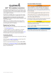
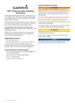
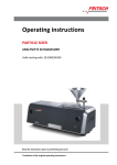
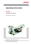
Operating instructions
UNIVERSAL CUTTING MILL
PULVERISETTE 19
Valid starting with: 19.10xx/0100
Read the instructions prior to performing any task!
Translation of the original operating instructions
Fritsch GmbH
Milling and Sizing
Industriestraße 8
55743 Idar-Oberstein
Telephone: +49 (0)6784/ 70-0
Fax: +49 (0)6784/ 70-11
email: [email protected]
Internet: www.fritsch.de
Version 09/2014 Index 008
Certifications and CE conformity
Certifications and CE conformity
Certification
Fritsch GmbH has been certified by the TÜV-Zertifizierungsgemeinschaft
e.V.
An audit certified that Fritsch GmbH conforms to the requirements of
the DIN EN ISO 9001:2008.
CE Conformity
The enclosed Conformity Declaration lists the guidelines the FRITSCH
instrument conforms to, to be able to bear the CE mark.
-3-
Table of contents
Table of contents
1
Basic structure............................................................................... 7
2
Safety information and use........................................................... 9
2.1 Requirements for the user..................................................... 9
2.2 Scope of application............................................................... 9
2.2.1 Operating principle........................................................... 10
2.3 Obligations of the operator................................................. 10
2.4 Information on hazards and symbols used in this manual. . 11
2.5 Device safety information.................................................... 13
2.6 Protective equipment.......................................................... 15
2.6.1 Opening the cutting mill without mains connection........ 15
2.7 Hazardous points................................................................. 16
2.8 Electrical safety.................................................................... 17
2.8.1 General information......................................................... 17
2.8.2 Protection against restart................................................. 17
2.8.3 Direction of rotation detection......................................... 17
2.8.4 Overload protection.......................................................... 17
3
Technical data..............................................................................
3.1 Dimensions..........................................................................
3.2 Weight..................................................................................
3.3 Operating noise....................................................................
3.4 Voltage.................................................................................
3.5 Current consumption...........................................................
3.6 Power consumption.............................................................
3.7 Motor shaft power in accordance with VDE 0530, EN
60034...................................................................................
3.8 Electrical fuses.....................................................................
3.9 Material................................................................................
3.10 Final fineness.....................................................................
3.11 Speed.................................................................................
18
18
18
18
18
18
18
Installation...................................................................................
4.1 Transport.............................................................................
4.2 Unpacking............................................................................
4.3 Setting up.............................................................................
4.4 Ambient conditions..............................................................
4.5 Fastening the Universal Cutting Mill....................................
4.6 Selecting and converting the funnels...................................
4.6.1 Selecting the funnel..........................................................
4.6.2 Converting from standard funnel to protected funnel.....
4.6.3 Converting from protected funnel to standard funnel.....
4.7 Electrical connection............................................................
20
20
20
20
20
21
21
21
22
22
23
4
-4-
19
19
19
19
19
Table of contents
5
Initial start-up..............................................................................
5.1 Before switching on for the first time..................................
5.2 Switching on.........................................................................
5.3 Function check.....................................................................
5.4 Switching off........................................................................
25
25
26
26
26
6
Using the device...........................................................................
6.1 Preparing a comminution....................................................
6.1.1 Opening the cutting mill...................................................
6.1.2 Inserting / changing the fixed knives................................
6.1.2.1 Installation position of the fixed knives.........................
6.1.2.2 Installation position of the fixed knives with tungsten
carbide cutting edge......................................................
6.1.3 Setting the gap width of the knives..................................
6.1.4 Inserting / changing a rotor..............................................
6.1.5 Inserting / changing a sieve cassette................................
6.1.5.1 Selecting the sieve cassette...........................................
6.1.6 Closing the cutting mill.....................................................
6.1.7 Checking if the rotor is turning freely...............................
6.2 Comminution procedure with standard funnel...................
6.2.1 Using the plunger..............................................................
6.3 Comminution procedure with the protected funnel...........
6.4 Overload of the cutting mill.................................................
6.5 Sample exhaust system with cyclone separator..................
28
28
28
29
29
7
Cleaning........................................................................................
7.1 Housing................................................................................
7.2 Cutting chamber..................................................................
7.3 Funnel..................................................................................
7.3.1 Standard funnel (1)...........................................................
7.3.2 Protected funnel (22)........................................................
7.3.2.1 Removing sample pusher (24).......................................
7.3.2.2 Removing the plunger (23)............................................
7.4 Collecting vessel...................................................................
7.5 Cleaning the sample exhaust system and cyclone separator.....................................................................................
7.6 Cleaning the filter foam mat (B)...........................................
30
30
31
33
33
34
34
35
36
36
37
39
42
42
42
43
43
44
44
45
45
46
46
8
Maintenance................................................................................ 47
9
Repairs......................................................................................... 51
9.1 Checklist for troubleshooting............................................... 51
10
Disposal........................................................................................ 53
11
Guarantee terms.......................................................................... 54
12
Exclusion of liability..................................................................... 56
-5-
Table of contents
13
Safety logbook............................................................................. 58
14
Index............................................................................................. 60
-6-
Basic structure
1
1
2
3
4
5
6
7
8
Basic structure
Standard funnel
Upper part of housing
Rotor
Fixed knife 1
Fixed knife 2
Closing lid
Sieve cassette
Collecting vessel
9
10
11
12
13
14
15
15*
-7-
Fixed knife 2
Lower part of housing
Lock
U-profile
Latch clamp
Motor cover
Safety switch
Safety switch bracket
Basic structure
1
14
18
19
20
21
Standard funnel
Motor cover
Ventilation grid
Control switch
Mains plug
Funnel lid
22
23
24
26
34
35
-8-
Protected funnel
Plunger (protected funnel)
Sample pusher
Plunger (standard funnel)
Start button
Stop button
Safety information and use
2
Safety information and use
2.1 Requirements for the user
This operating manual is intended for persons assigned with operating
and monitoring the Fritsch PULVERISETTE 19. The operating manual and
especially its safety instructions are to be observed by all persons
working on or with this device. In addition, the applicable rules and regulations for accident prevention at the installation site are to be observed.
Always keep the operating manual at the installation site of the PULVERISETTE 19.
People with health problems or under the influence of medication,
drugs, alcohol or exhaustion must not operate this device.
The PULVERISETTE 19 may only be operated by authorised persons and
serviced or repaired by trained specialists. All commissioning, maintenance and repair work may only be carried out by technically qualified
personnel. Qualified personnel are persons who, because of their education, experience and training as well as their knowledge of relevant
standards, regulations, accident prevention guidelines and operating
conditions, are authorised by those responsible for the safety of the
machine to carry out the required work and are able to recognize and
avoid possible hazards as defined for skilled workers in IEC 364.
In order to prevent hazards to users, follow the instructions in this
manual.
Malfunctions that impair the safety of persons, the PULVERISETTE 19 or
other material property must be rectified immediately. The following
information serves both the personal safety of operating personnel as
well as the safety of the products described and any devices connected
to them: All maintenance and repair work may only be performed by
technically qualified personnel.
This operating manual is not a complete technical description. Only the
details required for operation and maintaining usability are described.
Fritsch has prepared and reviewed this operating manual with the
greatest care. However, no guarantee is made for its completeness or
accuracy.
Subject to technical modifications.
2.2 Scope of application
The Universal Cutting Mill can be used for the fast comminution of soft,
medium-hard, brittle, tough and fibrous materials like:
Sheet rubber, plastics, refuse-derived fuel, dry meat, leather, wood, coal,
malt, paper/cardboard, peat, animal feed, pasta, tablets, leaves, pellets,
spices, fabric, straw, maize, bones, roots, tobacco...
-9-
Safety information and use
2.2.1
Operating principle
The material is fed through a funnel (example in image with standard
funnel) into the cutting chamber. There, rotating knives (3) in combination with fixed knives (4,5,9) cut the material. The fine ground material
falls through a sieve cassette (7) into the collecting vessel (8).
For fine comminution, the sample exhaust system can be used with
cyclone separator (optional accessory 45.5900.00).
2.3 Obligations of the operator
Before using the PULVERISETTE 19, this manual is to be carefully read
and understood. The use of the PULVERISETTE 19 requires technical
knowledge; only commercial use is permitted.
The operating personnel must be familiar with the content of the operating manual. For this reason, it is very important that these persons
actually receive the present operating manual. Ensure that the operating
manual is always near the device.
The PULVERISETTE 19 may exclusively be used within the scope of applications set down in this manual and within the framework of guidelines
put forth in this manual. In case of non-compliance or improper use, the
customer assumes full liability for the functional capability of the PULVERISETTE 19 and for any damage or injury arising from failure to fulfil
this obligation.
By using the PULVERISETTE 19 the customer agrees with this and recognizes that defects, malfunctions or errors cannot be completely
excluded. To prevent risk of damage to persons or property or of other
direct or indirect damage, resulting from this or other causes, the customer must implement sufficient and comprehensive safety measures
for working with the PULVERISETTE 19.
Neither compliance with this manual nor the conditions and methods
used during installation, operation, use and maintenance of the PULVERISETTE 19 can be monitored by Fritsch GmbH. Improper execution of
the installation can result in property damage and thus endanger persons. Therefore, we assume absolutely no responsibility or liability for
loss, damage or costs that result from errors at installation, improper
operation or improper use or improper maintenance or are in any way
connected to these.
- 10 -
Safety information and use
The applicable accident prevention guidelines must be complied with.
Generally applicable legal and other obligatory regulations regarding
environmental protection must be observed.
2.4 Information on hazards and symbols used in this manual
Safety information
Safety information in this manual is designated by symbols. Safety information is introduced by keywords that express the extent of the hazard.
DANGER!
This symbol and keyword combination points out a directly
hazardous situation that can result in death or serious
injury if not avoided.
WARNING!
This symbol and keyword combination points out a possibly
hazardous situation that can result in death or serious
injury if not avoided.
CAUTION!
This symbol and keyword combination points out a possibly
hazardous situation that can result in slight or minor injury
if not avoided.
NOTICE!
This symbol and keyword combination points out a possibly
hazardous situation that can result in property damage if
not avoided.
ENVIRONMENT!
This symbol and keyword combination points out a possibly
hazardous situation that can result in environmental
damage if not avoided.
Special safety information
To call attention to specific hazards, the following symbols are used in
the safety information:
- 11 -
Safety information and use
DANGER!
This symbol and keyword combination points out a directly
hazardous situation due to electrical current. Ignoring information with this designation will result in serious or fatal
injury.
DANGER!
This symbol and keyword combination designates contents
and instructions for proper use of the machine in explosive
areas or with explosive substances. Ignoring information
with this designation will result in serious or fatal injury.
DANGER!
This symbol and keyword combination designates contents
and instructions for proper use of the machine with combustible substances. Ignoring information with this designation will result in serious or fatal injury.
WARNING!
This symbol and keyword combination points out a directly
hazardous situation due to movable parts. Ignoring information with this designation can result in hand injuries.
WARNING!
This symbol and keyword combination points out a directly
hazardous situation due to hot surfaces. Ignoring information with this designation can result in serious burn injuries
due to skin contact with hot surfaces.
Safety information in the procedure
instructions
Safety information can refer to specific, individual procedure instructions. Such safety information is embedded in the procedure instructions
so that the text can be read without interruption as the procedure is
being carried out. The keywords described above are used.
- 12 -
Safety information and use
Example:
1.
Loosen screw.
2.
CAUTION!
Risk of entrapment at the lid.
Close the lid carefully.
3.
Tighten screw.
Tips and recommendations
This symbol emphasises useful tips and recommendations
as wells as information for efficient operation without mal‐
function.
Further designations
To emphasise procedure instructions, results, lists, references and other
elements, the following designations are used in this manual:
Designation
Explanation
Step-by-step procedure instructions
1., 2., 3. ...
ð
Results of steps in the procedure
References to sections in this manual and relevant documentation
Lists without a specific order
[Button]
Operating elements (e.g. push button, switch),
display elements (e.g. signal lamps)
‘Display’
Screen elements (e.g. buttons, function key
assignment)
2.5 Device safety information
Please observe!
n Only use original accessories and original spare parts. Failure to
observe this instruction can compromise the safety of the machine.
n Accident-proof conduct is to be strictly followed during all work.
n Comply with all currently applicable national and international accident prevention guidelines.
- 13 -
Safety information and use
CAUTION!
Wear hearing protection!
If a noise level of 85 dB(A) is reached or exceeded, ear protection should be worn to prevent hearing damage.
WARNING!
The maximum accepted concentration (MAC) levels of the
relevant safety guidelines must be observed; if necessary,
ventilation must be provided or the machine must be operated under an extractor hood.
DANGER!
Explosion hazard!
– When Comminution oxidizable substances, e.g. metals
or coal, there is a risk of spontaneous combustion (dust
explosion) if the share of fine particles exceeds a certain percentage. When Comminution these kinds of
substances, special safety measures must be taken and
the work must be supervised from a specialist.
– The PULVERISETTE 19 is not explosion protected and is
not designed to comminute explosive materials.
n Do not remove the information signs.
NOTICE!
Immediately replace damaged or illegible information signs.
n Unauthorised alteration of the PULVERISETTE 19 will void Fritsch's
declaration of conformity to European directives and void the guarantee.
n Only use the PULVERISETTE 19 when it is in proper working order, as
intended and in a safety- and hazard-conscious manner adhering to
the operating manual. In particular, immediately rectify any malfunctions that could pose a safety hazard.
n If, after reading the operating manual, there are still questions or
problems, please do not hesitate to contact our specialised personnel.
- 14 -
Safety information and use
2.6 Protective equipment
n Protective equipment is to be used as intended and may not be disabled or removed.
n All protective equipment is to be regularly checked for integrity and
proper functioning.
n The Universal Cutting Mill is equipped with a safety lock (11) which
also protects the operator. This locks the front closing lid (6) during
operation.
n The safety switches (11, 15) prevent operation of the Universal Cutting Mill, if the cutting chamber is not closed or a collecting vessel (8)
has not been inserted.
n Do not operate the device without a funnel (1 or 22)!
Funnels (1, 22) are mechanical safety devices that enable hazardfree filling.
n When changing the funnels (1, 22), disconnect the device from the
mains and install the new funnel (1, 22) immediately! (Ä Chapter 4.6
‘Selecting and converting the funnels’ on page 21)
n Motor safety switch (Ä Chapter 6.4 ‘Overload of the cutting mill’
on page 37)
2.6.1
Opening the cutting mill without mains connection
DANGER!
The lock (11) must only be released manually when the
closing lid (6) is closed.
The latch clamp (13) of the door must be locked!
1.
Insert the supplied triangular key into the bore hole under the
safety lock (11) and turn it clockwise.
2.
The closing lid (6) can be opened after opening the latch clamp
(13).
- 15 -
Safety information and use
3.
At this time, it is not possible to switch on the Universal Cutting
Mill. To switch it on, the safety lock (11) must be activated by
turning the triangular key to the left, the closing lid (6) must be
closed and the latch clamp (13) in locked position.
2.7 Hazardous points
n The closing lid (6) can be lifted out of the hinges. When opening the
upper part of the housing (2) it is possible to leave the closing lid (6)
in the hinge. If this is the case, ensure that the closing lid (6) does
not lift out of the hinge when opening the upper part of the housing
(2).
n When opening the upper part of the housing (2), there is an initial
resistance.
n Make sure that the closing lid (6) is fully open!
n When opening the upper part of the housing (2), slowly swivel it
open until the upper part of the housing (2) is resting on the rubber
buffer - do not let it fall down heavily.
n Crushing hazard when closing the upper part of the housing (2).
Close it slowly!
- 16 -
Safety information and use
n After checking if the rotor (3) is turning freely (Ä Chapter 6.1.7
‘Checking if the rotor is turning freely’ on page 34), the required hexagon socket screw key must be removed immediately.
2.8 Electrical safety
2.8.1
General information
n The switch (19) on the back is not a main switch but rather a control
switch. Therefore the mains plug (20) must be plugged out in order
to safely disconnect the supply voltage.
n Switch the control switch (19) on the back of the Universal Cutting
Mill to 0, if the device is to be idle for a longer period of time (e.g.
overnight).
2.8.2
Protection against restart
In the case of power failure during operation or after switching off with
the control switch (19), the closing lid (6) is locked. The lock (11) is
opened when power returns. However, for safety reasons the cutting
mill does not restart.
2.8.3
Direction of rotation detection
A unit for detection of the direction of rotation is installed in devices
with a three-phase motor:
If the STOP button (35) lights up red after connecting to a three-phase
power system and switching the control switch (19) to AUTO, the direction of rotation must be corrected. To do this, two phases in the mains
plug must be reversed. Ä Chapter 4.7 ‘Electrical connection’ on page 23.
2.8.4
Overload protection
n The motor protection switch switches off if overload occurs.
Ä Chapter 6.4 ‘Overload of the cutting mill’ on page 37. The STOP
button lights up red.
- 17 -
Technical data
3
Technical data
3.1 Dimensions
440 mm x 550 mm x 630 mm
(width x depth x height)
3.2 Weight
n 56 - 65 kg (net)
n 86 - 95 kg (gross)
3.3 Operating noise
The noise level is approx. 78 dB (A) when idle and 95 dB (A) when idle
incl. cyclone separator. The value fluctuates strongly depending on the
comminution material.
3.4 Voltage
n 400V / 3~
n 230V / 1~
n 100-120V / 1~
3.5 Current consumption
n 16A for 400V / 3~ motor
n 16A for 230V / 1~ motor
n 15A for 100-120V / 1~ motor
(Ä Chapter 4.7 ‘Electrical connection’ on page 23)
Transient overvoltage according to overvoltage category II is permitted.
3.6 Power consumption
n
n
n
n
3240 W for 400V / 3~ motor
2000 W for 400V / 3~ motor
2200 W for 230V / 1~ motor
1850 W for 100-120V / 1~ motor
- 18 -
Technical data
3.7 Motor shaft power in accordance with VDE 0530, EN 60034
n
n
n
n
2.2 kW for 400V / 3~ motor
1.5 kW for 400V / 3~ motor
1.5 kW for 230V / 1~ motor
1.1 kW for 100-120V / 1~ motor
3.8 Electrical fuses
n Circuit breaker in device
n Micro-fuse in device
n Motor safety switch (Ä Chapter 6.4 ‘Overload of the cutting mill’
on page 37)
n Direction of rotation detection in three-phase model (Ä Chapter 2.8
‘Electrical safety’ on page 17)
3.9 Material
Depending on material and funnel (1, 22) up to 70 x 80 mm. Harder
material max. 10 mm.
Feed size
Batchwise feeding!
Throughput
3.10
Depending on material property and sieve used, up to 60 l/h.
Final fineness
Achievable average final fineness depending on sieve insert, 0.2 - 6 mm.
3.11
Speed
50 Hz
60 Hz
Order No.:
302 -
1168 rpm/min
19.108x.00
2800 -
3400 rpm/min
19.10x0.00
- 19 -
Installation
4
Installation
4.1 Transport
n Transport on transport palette with a forklift or pallet truck.
n When lifting the device hold it underneath at the back and front
only. Do not lift it using the plastic cover.
CAUTION!
When lifting, at least 2 persons are required!
4.2 Unpacking
n Pull out the nails that fasten the crate to the transport pallet.
n Lift the crate off the transport pallet.
n Compare the contents of the delivery with your order.
4.3 Setting up
n 4 screws connect the cutting mill to the transport pallet.
Remove the 4 screws.
n Lift the cutting mill off the transport pallet.
CAUTION!
At least 2 persons are required to lift it off!
4.4 Ambient conditions
The device may only be operated indoors.
The surrounding air may not carry any electrically conductive dust.
The room temperature should be between 5 and 40 °C.
Altitudes up to 2000 m NN.
Maximum relative humidity 80% for temperatures up to 31 °C, linearly decreasing down to 50% relative humidity at 40 °C.
n Degree of pollution 2 according to IEC 664.
n
n
n
n
n
- 20 -
Installation
4.5 Fastening the Universal Cutting Mill
Screw the cutting mill tightly to the stand provided (acc. to instructions)
or to a stable mount (table...). The following must be observed in order
to fasten the device:
n Unscrew the 3 screws fastening the motor cover (14).
n Lift the motor cover (14) off carefully.
n Two U-profiles (12) are mounted on the bottom of the device. Insert
the 4 screws provided through the bore holes in the U-profiles (12)
and screw them tightly to the stand or table. Other screws with the
same diameter can also be used.
WARNING!
Ensure that the device is safely fastened. Sizeable lateral
forces can occur!
NOTICE!
Make sure that the Universal Cutting Mill is easily accessible. On the right of the mill there must be enough space
to lift open the upper part of the housing (2) incl. funnel (1,
22).
Keep the ventilation grate (18) on the back free. Risk of
overheating!
4.6 Selecting and converting the funnels
4.6.1
Selecting the funnel
The standard funnel (1) is used for long and bulk solids, for free-flowing
material, but also for the comminution of long goods, like for example
straw or wood. The protected funnel (22) is used for all other materials.
- 21 -
Installation
4.6.2
Converting from standard funnel to protected funnel
1.
Close the cutting mill.
2.
Switch the control switch (19) on the back of the device to 0.
3.
Remove the mains plug (20).
4.
Unscrew the four M6x12 hexagon bolts fastening the standard
funnel (1) to the upper part of the housing (2) using a hexagon
socket screw key and lift off the standard funnel (1).
5.
Insert the protected funnel (22) and fasten it with the four M6x12
hexagon bolts and the washers.
6.
Connect the device again to the mains.
ð The device is ready for operation.
4.6.3
Converting from protected funnel to standard funnel
1.
Close the cutting mill.
2.
Close the funnel lid (21).
- 22 -
Installation
3.
Switch the control switch (19) on the back of the device to 0.
4.
Remove the mains plug (20).
5.
Unscrew the four M6x12 hexagon bolts fastening the protected
funnel (22) to the upper part of the housing (2) using a hexagon
socket screw key and lift off the protected funnel (22).
6.
Insert the standard funnel (1) and fasten it with the four M6x12
hexagon bolts and the washers.
7.
Connect the device again to the mains.
8.
Switch the control switch (19) on the back of the device to AUTO.
ð The device is ready for operation.
4.7 Electrical connection
Before establishing the connection, compare the voltage and current
values stated on the type plate with the values of the mains system to be
used.
(see Ä Chapter 3 ‘Technical data’ on page 18).
- 23 -
Installation
If the STOP button lights up red after connection to a three-phase
power system and switching the control switch (19) to AUTO, the direction of rotation must be corrected. To do this, two phases in the mains
plug must be reversed.
DANGER!
Changes to the connection line may only be made by a
qualified person.
- 24 -
Initial start-up
5
Initial start-up
5.1 Before switching on for the first time
1.
Connect the device to the mains with the mains plug (20).
2.
Switch the control switch (19) on the back of the device to AUTO.
The START button must light up green. If the STOP button lights up
red, see Ä Chapter 4.7 ‘Electrical connection’ on page 23.
3.
Switch the control switch (19) on the back of the device to AUTO.
4.
Remove the cover cap (Z) of the central bore hole in the closing lid
(6).
5.
Insert the hexagon socket screw key provided through the central
bore hole. Now turn the hexagon socket screw key to check if the
rotor (3) is turning freely.
- 25 -
Initial start-up
6.
Remove the hexagon socket screw key again!
7.
If the rotor (3) is not turning freely, proceed as described in
Ä Chapter 6.1.3 ‘Setting the gap width of the knives’ on page 30.
NOTICE!
This check must also be carried out every time the
rotor (3), the fixed knives (4, 5, 9) and the sieve cassette (7) are changed!
5.2 Switching on
1.
Check again that the cutting mill is firmly fastened.
2.
Check that the funnel (1, 22) is firmly mounted and closed.
3.
Push in the collecting vessel (8) or the adapter for the sample
exhaust system (27) (see Ä Chapter 6.5 ‘Sample exhaust system
with cyclone separator’ on page 39).
4.
Check if the latch clamp (13) is closed.
5.
Switch the control switch (19) on the back of the device to AUTO,
the START button must light up green.
5.3 Function check
Switch on the device by pressing the START button. This front closing lid
(6) is now locked.
® The cutting mill starts up.
NOTICE!
Switch the device off immediately if there is an audible
metal contact noise. This can happen if the fixed knives are
set incorrectly. An indication of this could be shiny areas on
the rotor, which show where the fixed knives must be readjusted. (See Ä Chapter 6.1.2 ‘Inserting / changing the fixed
knives’ on page 29)
5.4 Switching off
Press the STOP button to switch off the device. After waiting a few seconds the closing lid (6) can be opened.
Switch off the main switch (19) if the cutting mill is to be idle for a longer
period of time (e.g. overnight).
- 26 -
Initial start-up
The switch (19) on the back is not a main switch but rather
a control switch. Therefore the mains plug (20) must be
plugged out in order to safely disconnect the supply voltage.
CAUTION!
Never unlock the latch clamp (13) during operation!
Risk of severe and permanent damage to the rotor (3).
- 27 -
Using the device
6
Using the device
6.1 Preparing a comminution
6.1.1
Opening the cutting mill
1.
Switch the control switch (19) on the back of the device to AUTO.
2.
Unlock the latch clamp (13).
3.
Open the closing lid (6). It is possible to lift the closing lid (6) out of
the hinge after opening. However this is only necessary, for
example, for cleaning.
4.
Make sure that the closing lid (6) is fully open!
Slowly swivel open the upper part of the housing (2) until it is
resting on the rubber buffer.
- 28 -
Using the device
6.1.2
6.1.2.1
Inserting / changing the fixed knives
1.
Open the cutting mill (see Ä Chapter 6.1.1 ‘Opening the cutting
mill’ on page 28)
2.
When inserting or changing the fixed knives (4, 5, 9) the rotor (3)
and the sieve cassette (7) must be removed (see Ä Chapter 6.1.4
‘Inserting / changing a rotor’ on page 31 and Ä Chapter 6.1.5
‘Inserting / changing a sieve cassette’ on page 33).
3.
Loosen the retaining screws (A) to change or remove the fixed
knives (4, 5, 9).
4.
When inserting, fasten the fixed knives (4, 5, 9) with the retaining
screw (A).
5.
After mounting the rotor (3) (see Ä Chapter 6.1.4 ‘Inserting /
changing a rotor’ on page 31) set the gap width of the knives (see
Ä Chapter 6.1.3 ‘Setting the gap width of the knives’ on page 30).
Installation position of the fixed knives
(9) Fixed knife 2
(4) Fixed knife 1
(5) Fixed knife 2
- 29 -
Using the device
6.1.2.2
Installation position of the fixed knives with tungsten carbide cutting edge
(9) Fixed knife 2
(4) Fixed knife 1
(5) Fixed knife 2
NOTICE!
Observe the position of the strips of hardmetal tungsten
carbide. These are marked in BLUE in the image above.
6.1.3
Setting the gap width of the knives
The knife gap is set at the factory to approx. 0.2 mm.
A
B
1.
Open the cutting mill (see Ä Chapter 6.1.1 ‘Opening the cutting
mill’ on page 28) but set the control switch (19) on the back of the
device to HAND.
2.
Loosen the middle retaining screws (A) on all 3 fixed knives (4, 5,
9) and unscrew them slightly.
3.
Turn the rotor (3) so that the rotor knife and the fixed knife (4, 5,
9) are exactly opposite each other.
Retaining screw to fasten and loosen
the fixed knife when setting the gap
width of the knives.
Threaded pins to set the cutting gap.
- 30 -
Using the device
4.
Screw in the right and left threaded pins (B) beside the retaining
screw (A) equally until the fixed knives (4, 5, 9) come up against
the rotor knives.
5.
Then turn the threaded pins (B) evenly back by ¼ of a turn and
retighten the retaining screw (A).
6.
Set all 3 fixed knives (4, 5, 9) in this way.
A knife gap of approx. 0.2 mm is then set using this method. This
can be checked using a feeler gauge. (0.2 mm, approx. 2 sheets of
printing paper, DIN A4 80 g)
A, B (9)
A, B (4,
5)
Retaining screw (A) and
threaded pins (B) for fixed
knife (9)
Retaining screws (A) and
threaded pins (B) for fixed
knife (4, 5)
NOTICE!
The fixed knives (4, 5, 9) must run parallel to the
rotor knives so that the cutting load is distributed
evenly across the whole length.
7.
Insert the sieve cassette (7) (see Ä Chapter 6.1.5 ‘Inserting /
changing a sieve cassette’ on page 33).
8.
Close the cutting mill (see Ä Chapter 6.1.6 ‘Closing the cutting
mill’ on page 34).
NOTICE!
Check if the rotor (3) is turning freely (see
Ä Chapter 6.1.7 ‘Checking if the rotor is turning
freely’ on page 34).
If this is not the case, proceed as described in
Ä Chapter 6.1.3 ‘Setting the gap width of the knives’
on page 30.
This check must also be carried out every time the
rotor (3) is changed!
6.1.4
Inserting / changing a rotor
CAUTION!
Risk of injury!
Beware of the sharp edges of the rotor!
Wear safety gloves when changing the rotor!
- 31 -
Using the device
1.
Open the cutting mill (see Ä Chapter 6.1.1 ‘Opening the cutting
mill’ on page 28).
2.
Pull the rotor (3) forwards, wearing safety gloves. If the rotor (3)
jams somewhat, lever it out carefully.
3.
Clean the cone-shaped rotor holders (3).
4.
Clean both cone-shaped holders (cones) in the closing lid (6) and
on the holder.
5.
Push the rotor (3) onto the rotor holder. Turn it clockwise until it
engages in the 4 driving pins (C) on the back. (The control switch
(19) must be at AUTO)
- 32 -
Using the device
6.
Close the cutting mill (see Ä Chapter 6.1.6 ‘Closing the cutting
mill’ on page 34).
NOTICE!
Check if the rotor (3) is turning freely (see
Ä Chapter 6.1.7 ‘Checking if the rotor is turning
freely’ on page 34).
If this is not the case, proceed as described in
Ä Chapter 6.1.3 ‘Setting the gap width of the knives’
on page 30.
This check must also be carried out every time the
rotor (3) is changed!
6.1.5
Inserting / changing a sieve cassette
1.
Open the cutting mill (see Ä Chapter 6.1.1 ‘Opening the cutting
mill’ on page 28).
2.
Pull out the sieve cassette (7) to the front. The rotor (3) must not
be removed.
If necessary, use the pulling tool (X) 45.5550.10 to pull out the
sieve cassette (7): Insert the pulling tool into the two holes of the
sieve cassette (7) past the bends of the pulling tool. While
inserting the pulling tool, move it slightly up and down.
6.1.5.1
3.
If the sieve cassette (7) is jammed, remove the comminution
material under the fixed knife (9) on the left side of the housing
with a screwdriver.
4.
Before pushing in the sieve cassette (7) clean the cutting chamber
thoroughly, so that everything can be closed tightly again.
5.
Close the cutting mill (see Ä Chapter 6.1.6 ‘Closing the cutting
mill’ on page 34).
Selecting the sieve cassette
Coarse material should be roughly crushed with the coarse 2-4 mm sieve
and comminuted in the second work step to the desired final fineness.
The sample exhaust system with cyclone separator (optional accessory,
see Ä Chapter 6.5 ‘Sample exhaust system with cyclone separator’
on page 39) can be used for fine comminution < 2 mm.
- 33 -
Using the device
6.1.6
6.1.7
Closing the cutting mill
1.
Before closing the cutting mill, clean the cutting chamber, the contact surfaces of the housing and, in particular, the locking surfaces
of the lock.
2.
Swivel the upper part of the housing (2) slowly closed until it is
resting on the lower part of the housing (10).
3.
Close the closing lid (6).
4.
Lock the latch clamp (13).
5.
Switch the control switch (19) on the back of the device to HAND.
Checking if the rotor is turning freely
n To check if the rotor is turning freely, the closing lid (6) must be
closed. (See Ä Chapter 6.1.6 ‘Closing the cutting mill’ on page 34)
n Remove the cover cap (Z) of the central bore hole in the closing lid
(6).
n Guide the hexagon socket screw key provided through the central
bore hole in the closing lid (6).
n Now turn the hexagon socket screw key to check if the rotor (3) is
turning freely.
- 34 -
Using the device
n Remove the hexagon socket screw key again immediately!
n If the rotor (3) is not turning freely, proceed as described in
Ä Chapter 6.1.3 ‘Setting the gap width of the knives’ on page 30.
NOTICE!
This check must also be carried out every time the rotor (3)
and the fixed knives (4, 5, 9) are changed!
6.2 Comminution procedure with standard funnel
CAUTION!
Wear safety goggles for comminution using the standard
funnel!
There is a risk of particles from the funnel being projected,
in the case of free-flowing material.
1.
Switch the control switch (19) on the back of the device to AUTO.
2.
Close the cutting mill (see Ä Chapter 6.1.6 ‘Closing the cutting
mill’ on page 34).
3.
Push in the collecting vessel (8).
4.
Pull the plunger (26) out fully.
5.
Switch on the deviceà press the green Start button (see
Ä Chapter 5.2 ‘Switching on’ on page 26).
6.
Add some comminution material.
⇒An operating noise becomes audible.
The quantity of comminution material is based on the particle feed
size and the grindability of the comminution material. It is best to
start with small quantities and increase them depending on the
success of the comminution.
7.
If necessary, press the comminution material into the cutting
chamber with the plunger (26).
8.
When the operating noise becomes quieter, the comminution procedure is complete.
ð More comminution material can be added in.
- 35 -
Using the device
6.2.1
Using the plunger
The plunger has 2 different sides for feeding the sample material in the
funnel to the grinding chamber. On the one hand, the smooth, round
side is suitable for finer material. On the other hand, the cross-shaped,
thinner side is suitable for long, fibrous material, like straw.
6.3 Comminution procedure with the protected funnel
1.
Switch the control switch (19) on the back of the device to AUTO.
2.
Close the cutting mill (see Ä Chapter 6.1.6 ‘Closing the cutting
mill’ on page 34).
3.
Push in the collecting vessel (8).
4.
Pull the sample pusher (24) out fully.
5.
Move the plunger (23) into the lower position.
6.
Flip open the funnel lid (21), add some comminution material and
close the lid again.
The quantity of comminution material is based on the particle feed
size and the grindability of the comminution material. It is best to
start with small quantities and increase them depending on the
success of the comminution.
7.
Switch on the deviceà press the green Start (34) button (see
Ä Chapter 5.2 ‘Switching on’ on page 26).
8.
Move the sample pusher (24) down towards the plunger (23) until
the comminution material is in front of the plunger (23).
9.
Pull the plunger (23) upwards and move the sample pusher (24)
fully downwards until the comminution material falls into the cutting chamber.
ð a slight operating noise becomes audible.
- 36 -
Using the device
10.
Leave the sample pusher (24) down and move the plunger (23)
downwards.
ð The operating noise becomes louder.
11.
Make pumping movements with the plunger (23). These pumping
movements draw in and press out air through the blower filter
above the collecting vessel. This air feeds the comminution material through the sieve or lifts it off the sieve and feeds it to the
process again.
12.
When the operating noise becomes quieter, the cutting procedure
is complete.
ð More comminution material can be added in.
6.4 Overload of the cutting mill
When filling and making downward movements with the plunger (23)
the working noise must be observed. The sound level is nearly identical
to the load on the machine. You can clearly hear from the pitch when the
mill reduces speed due to overload.
Pulling the plunger (23) out on time reduces the load on the mill and protects the rotor (3), the fixed knives (4, 5, 9) and the sieve cassette (7).
NOTICE!
If the cutting mill is overloaded, the motor protection
switch switches the device off.
The red Stop button lights up to indicate overload.
Then proceed as follows:
1.
Switch the control switch (19) on the back of the device to 0.
2.
Disconnect the cutting mill from the mains (remove the mains plug
(20) from the socket).
3.
Allow the device to cool down.
4.
Unscrew the 3 screws fastening the motor cover (14).
- 37 -
Using the device
5.
Lift the motor cover (14) off carefully.
6.
Press the blue Reset switch. This must be set to "H".
7.
Replace the motor cover (14) and screw it tight.
8.
Connect the device again to the mains.
9.
Switch the control switch (19) on the back of the device to AUTO.
ð the Start button lights up green. The device is ready for operation.
- 38 -
Using the device
6.5 Sample exhaust system with cyclone separator
CAUTION!
Hearing damage!
Wear hearing protection during sample extraction with the
cyclone separator!
(Optional accessory order number: 45.5900.00)
The sample exhaust system with cyclone separator can be used for fine
comminution.
27
28
29
30
31
32
33
1.
Adapter for exhaust system
Connection hose
Rubber sleeve
Cyclone separator (air separator)
Power vacuum
Sample bottle
Adapter for sample bottle
Push the adapter for the exhaust system (27) as well as the collecting vessel (8) into the lower part of the housing (10).
When using the cyclone separator, the filter above
the collecting vessel is automatically covered by the
adapter.
- 39 -
Using the device
2.
Attach one end of the connection hose (28) with the rubber sleeve
(29) to the adapter (27) and the other end to the cyclone separator (30).
NOTICE!
There are 2 opposing hose connections on the
cyclone separator (30). Do not use the sealed connection; leave it closed. This would increase the noise
level!
3.
Close the cutting mill with mounted standard funnel (1) (see
Ä Chapter 6.1.6 ‘Closing the cutting mill’ on page 34).
4.
Screw the sample bottle (31) onto the adapter (33) on the bottom
of the cyclone separator (30); make sure the connection hose is
firmly connected and switch on the exhaust system.
5.
Switch on the cutting mill (see Ä Chapter 5.2 ‘Switching on’
on page 26).
6.
Add a little comminution material by hand and observe the operating noises. If the motor speed decreases audibly, reduce the
supply of comminution material. A fast vortex of comminution
material must form in the collection bottle.
- 40 -
Using the device
The quantity of comminution material is based on the particle feed size
and the grindability of the material. It is best to start with small quantities and increase them depending on the success of the comminution.
NOTICE!
When the sample bottle (32) is 2/3 full, stop the comminution. To do this, switch off the cutting mill (see
Ä Chapter 5.4 ‘Switching off’ on page 26) and the sample
exhaust system. Then empty the sample bottle (32).
If comminution has not stopped when the bottle is 2/3 full, the effectiveness of the classifier is impaired and material will gradually clog the filter
of the sample exhaust system.
If the vortex of comminution material in the collection bottle slows
down, this means that the air throughput or air flow rate has decreased:
n grinding chamber is too full
n the sieve has to be cleaned and / or
n the filter of the exhaust system has to be cleaned.
NOTICE!
The fine material (fine dust) of the sample collects in the
filter of the sample exhaust system. Clean the filter from
time to time by vacuuming or blowing out.
The sample exhaust system is recommended especially in combination
with the standard funnel (1) for bulk and long solids.
- 41 -
Cleaning
7
Cleaning
7.1 Housing
The cutting mill can be wiped down with a damp cloth when it is
switched off. Disconnect the mains plug (20) from the electricity.
DANGER!
Do not allow any liquids to flow into the device.
7.2 Cutting chamber
Clean the cutting chamber with a dust exhaust system and brush and
also with compressed air, if necessary.
CAUTION!
Beware of dust exposure caused by cleaning with compressed air!
CAUTION!
Risk of entrapment!
When the control switch is at the "HAND" position, the
rotor can be turned freely in both directions!
1.
Switch the control switch (19) on the back of the device to HAND.
2.
Unlock the latch clamp (13).
3.
Open the closing lid (6) fully. This can be lifted out of the hinge at
an opening angle of 90° for cleaning.
- 42 -
Cleaning
4.
Slowly swivel open the upper part of the housing (2) with the
closing lid (6) fully open, until it is resting on the rubber buffer.
5.
Clean the cutting chamber.
7.3 Funnel
Clean the funnels (1, 22) with a dust exhaust system and brush and also
with compressed air, if necessary.
7.3.1
Standard funnel (1)
1.
With the cutting chamber open, vacuum out the funnel from
below
2.
Clean the funnel from above.
- 43 -
Cleaning
7.3.2
Protected funnel (22)
1.
Switch the control switch (19) on the back of the device to 0.
2.
Pull the sample pusher (24) out of the protected funnel (22) until it
stops and fasten it with knurled screw (A).
3.
Open the funnel lid (21).
4.
Clean the protected funnel (22) from above.
5.
Close the funnel lid (21).
6.
Pull the plunger (23) out of the protected funnel (22) until it stops
and fasten it with knurled screw (B).
7.
Open the cutting chamber as described above.
8.
Clean the protected funnel (22) from below.
If necessary!
It is also possible to remove the plunger (23) and the sample pusher (24)
for cleaning. Switch the control switch (19) on the back of the device to 0
and disconnect the mains plug (20) from the electricity.
7.3.2.1
Removing sample pusher (24)
1.
Open the funnel lid (21).
2.
Unscrew the knurled screws (C) and (A).
3.
The sample pusher (24) can be taken out.
4.
Install in reverse order.
- 44 -
Cleaning
7.3.2.2
Removing the plunger (23)
1.
Open the funnel lid (21).
2.
Unscrew the cross-head screws (D) with a screwdriver.
3.
Close the funnel lid (21).
4.
Unscrew the Torx screws (E) with a screwdriver.
5.
Unscrew the knurled screw (B).
6.
The plunger (23) can be taken out.
7.
Install in reverse order.
7.4 Collecting vessel
Pull out the collecting vessel (8) and clean it. It can be vacuumed or
wiped down with a damp cloth.
NOTICE!
Close the cutting mill after cleaning and check for proper
functioning. See Ä Chapter 5 ‘Initial start‐up’ on page 25.
NOTICE!
Make sure that the parts sit firmly when assembling.
- 45 -
Cleaning
7.5 Cleaning the sample exhaust system and cyclone separator
The exhaust system can be disassembled and cleaned after opening the
clips (F). To open and clean the cyclone separator, 4 screws in the inner
part of the base must be loosened.
7.6 Cleaning the filter foam mat (B)
1.
Vacuum the filter foam mat with the dust exhaust system
2.
Subsequently wash it out with water. If necessary, you could use a
tenside for cleaning.
3.
Allow the foam mat to air-dry!
- 46 -
Maintenance
8
Maintenance
25 Exhaust filter
A Filter holder
B Filter foam mat
NOTICE!
Before starting maintenance work, that does not require
mains voltage, unplug the mains plug (20) and protect the
device against being unintentionally switched back on
again!
Indicate maintenance work with warning signs.
The most important element of maintenance of the cutting mill is regular
cleaning (Ä Chapter 7 ‘Cleaning’ on page 42).
We recommend keeping a safety logbook Ä Chapter 13
‘Safety logbook’ on page 58, where all work (maintenance,
repairs......) performed on the device is entered.
- 47 -
Maintenance
Function / Functional part
Task
Test
Maintenance interval
Exhaust filter (25)
Filtering exhaust air
Clean exhaust filter (25). To do this, lever out Before every commithe filter holder (A) with a screwdriver or
nution
similar. Beat the filter foam mat (B). Clean
using compressed air or dust exhaust system.
Replace the filter foam mat (B) if it is very
heavily soiled. Article number: 90.0740.16
filter foam mat.
Safety lock (11)
Locking the closing lid
(6)
Is the closing lid (6) locked when control
switch (19) is set to 0? If NOT à safety lock
(11) defective. Disconnect the device from
the mains immediately. Replace the safety
lock (11).
Before each use
Safety switch (15)
Protecting the lower
opening of the cutting
chamber
Is the cutting mill running without the collecting vessel (8) or the adapter for exhaust
system (27)? If YES à safety switch (15)
defective. Disconnect the device from the
mains immediately. Replace the safety
switch (15).
Before each use
START button
Indicating readiness
for operation
Does the START button light up green if the
control switch (19) is set to AUTO or HAND?
If not, see Ä Chapter 11 ‘Guarantee terms’
on page 54.
Before each use
Rotor (3)
Comminuting material Is the rotor (3) sharp? Maintenance:
resharpen
Before each use
Fixed knives (4, 5,
9)
Comminuting material Are the fixed knives (4, 5, 9) sharp? Check
visually! Maintenance: resharpen
Before each use
Cutting gap
Cutting procedure
Measure gap width. For setting see
Whenever rotor and
Ä Chapter 6.1.3 ‘Setting the gap width of the fixed knives are
changed
knives’ on page 30.
Cones
Centring rotor (3)
Check cones for cleanliness and grooves. See Whenever rotor is
Ä Chapter 6.1.4 ‘Inserting / changing a rotor’ changed
on page 31.
Filter, sieve and
sample exhaust
system
Filtering exhaust air
Vortex of comminution material in the collec- Before each use
tion bottle slows down! For cleaning see
Ä Chapter 7 ‘Cleaning’ on page 42!
- 48 -
Maintenance
- 49 -
Maintenance
- 50 -
Repairs
9
Repairs
DANGER!
Mains voltage!
– Before beginning with repair work, unplug the mains
plug and protect the device against being unintentionally switched back on.
– Indicate repair work with warning signs.
– Repair work may only be performed by specialised personnel.
– Put safety equipment back into operation after maintenance work.
9.1 Checklist for troubleshooting
Fault description
Cause
Remedy
Start button does not light up
green
No mains connection
Plug in mains plug (20)
The control switch (19) is at 0
Set the control switch (19) to AUTO or HAND
Incorrect direction of rotation
Reverse two phases (Ä Chapter 4.7 ‘Electrical
connection’ on page 23
Socket fuse is faulty
Check socket fuse
Device fuse blown
Remove the housing and replace the fuse
Closing lid (6) not closed properly
Clean contact surface, close closing lid (6)
Collecting vessel (8) or adapter
for exhaust system (27) not
inserted properly
Insert collecting vessel (8) or adapter for exhaust
system (27) properly ® until safety switch (15)
engages.
The control switch (19) is set to
HAND.
Switch the control switch to AUTO.
Coarse samples were added to
the machine first and are
blocking rotor start-up.
Open grinding chamber and remove sample
material. ® Switch on device before adding
sample.
Mill stops running
Motor safety switch has triggered
Motor safety switch (see Ä Chapter 6.4 ‘Over‐
load of the cutting mill’ on page 37)
STOP button lights up red
Incorrect direction of rotation
Swap two phases in the mains plug (20)
(Ä Chapter 4.7 ‘Electrical connection’
on page 23)
START button is pressed but
mill does not start up
Too much comminution material Reduce feeding amount
in grinding chamber
- 51 -
Repairs
Fault description
Cause
Remedy
Comminution material is
escaping
Material is extremely fine
Insert sample exhaust system (see Ä Chapter 6.5
‘Sample exhaust system with cyclone separator’
on page 39)
Runs unevenly with strong
vibrations
Rotor imbalance
Cones soiled (see Ä Chapter 6.1.4 ‘Inserting /
changing a rotor’ on page 31)
Bearing in closing lid (6) defective
Replace bearing
Pieces broken off rotor (3)
Replace rotor (3) (Ä Chapter 6.1.4 ‘Inserting /
changing a rotor’ on page 31)
Rotor and fixed knives are
touching each other (audible
metal contact noise)
Switch device off immediately, disconnect from
mains, check gap widths and correct. Check rotor
and fixed knives for damage. (See
Ä Chapter 6.1.2 ‘Inserting / changing the fixed
knives’ on page 29)
- 52 -
Disposal
10
Disposal
It is hereby confirmed that FRITSCH has implemented the directive
2002/95/EC of the European Parliament and Council from 27th January
2003 for the limitation of the use of certain dangerous substances in
electrical and electronic devices.
FRITSCH has registered the following categories according to the German
electrical and electronic equipment act, section 6, paragraph 1, clause 1
and section 17, paragraphs 1 and 2:
Mills and devices for the preparation of samples have been registered
under category 6 for electrical and electronic tools (except for large stationary industrial tools).
Analytical devices have been registered under category 9, monitoring
and control instruments.
It has been accepted that FRITSCH is operating only in the business-tobusiness area. The German registration number for FRITSCH is WEEE reg.
no. DE 60198769
FRITSCH WEEE coverage
Since the registration of FRITSCH is classified for bilateral transactions,
no legal recycling or disposal process is described. FRITSCH is not obliged
to take back used FRITSCH devices.
FRITSCH declares it is prepared to take back used FRITSCH devices for
recycling or disposal free of charge whenever a new device is purchased.
The used FRITSCH device must be delivered free of charge to a FRITSCH
establishment.
In all other cases FRITSCH takes back used FRITSCH devices for recycling
or disposal only against payment.
- 53 -
Guarantee terms
11
Guarantee terms
Guarantee period
As manufacturer, FRITSCH GmbH provides – above and beyond any guarantee claims against the seller – a guaranty valid for the duration of two
years from the date of issue of the guarantee certificate supplied with
the device.
Within this guarantee period, we shall remedy all deficiencies due to
material or manufacturing defects free of charge. Rectification may take
the form of either repair or replacement of the device, at our sole discretion. The guarantee may be redeemed in all countries in which this
FRITSCH device is sold with our authorisation.
Conditions for claims against the guarantee
This guarantee is subject to the condition that the device is operated
according to the instructions for use / operating manual and its intended
use.
Claims against the guarantee must include presentation of the original
receipt, stating the date of purchase and name of the dealer, together
with the complete device type and serial number.
For this guarantee to take effect, the answer card entitled "Securing of
Guarantee" (enclosed with the device) must be properly filled out and
despatched without delay after receipt of the device and be received
by us within three weeks or alternatively, online registration must be
carried out with the above-mentioned information.
Reasons for loss of the guarantee
The guarantee will not be granted in cases where:
n Damage has arisen due to normal wear and tear, especially for wear
parts, such as: Crushing jaws, support walls, grinding bowls, grinding
balls, sieve plates, brush strips, grinding sets, grinding disks, rotors,
sieve rings, pin inserts, conversion kits, sieve inserts, bottom sieves,
grinding inserts, cutting tools, sieve cassettes, sieve and measuring
cell glasses.
n Repairs, adaptations or modifications were made to the device by
unauthorized persons or companies.
n The device was not used in a laboratory environment and/or has
been used in continuous operation.
n Damage is present due to external factors (lightning, water, fire or
similar) or improper handling.
n Damage is present that only insubstantially affects the value or
proper functioning of the device.
n The device type or serial number on the device has been changed,
deleted, removed or in any other way rendered illegible
n The above-mentioned documents have been changed in any way or
rendered illegible.
- 54 -
Guarantee terms
Costs not covered by the guarantee
This guarantee excludes any costs for transport, packaging or travel that
accrue in the event the product must be sent to us or in the event that
one of our specialist technicians is required to come to your site. Any
servicing done by persons not authorised by us and any use of parts that
are not original FRITSCH accessories and spare parts will void the guarantee.
Further information about the guarantee
The guarantee period will neither extend nor will a new period of guarantee begin in the event that a claim is placed against the guarantee.
Please provide a detailed description of the type of error or the complaint. If no error description is enclosed, we shall interpret the shipment
as an assignment to remedy all recognisable errors or faults, including
those not covered by the guarantee. Errors or faults not covered by the
guarantee shall in this case be rectified at cost.
We recommend reading the operating manual before contacting us or
your dealer, in order to avoid unnecessary inconvenience.
Ownership of defective parts is transferred to us with the delivery of the
replacement part; the defective part shall be returned to us at buyer's
expense.
NOTICE!
Please note that in the event that the device must be
returned, the device must be shipped in the original Fritsch
packaging. Fritsch GmbH denies all liability for any damage
due to improper packaging (packaging not from Fritsch).
Any enquiries must include a reference to the serial number imprinted
on the type plate.
- 55 -
Exclusion of liability
12
Exclusion of liability
Before using the product, be sure to have read and understood this
operating manual.
The use of the product requires technical knowledge; only commercial
use is permitted.
The product may be used exclusively within the scope of applications set
down in this operating manual and within the framework of guidelines
put forth in this operating manual and must be subject to regular maintenance. In case of non-compliance, improper use or improper maintenance, the customer assumes full liability for the functional capability of
the product and for damage or injury arising from violating these obligations.
The contents of this operating manual are subject in entirety to copyright law. This operating manual and its contents may not be copied, further distributed or stored in any form, in part or in whole, without the
prior written consent of Fritsch.
This operating manual has been prepared to the best of our knowledge
and checked for accuracy at the time of printing. FRITSCH GMBH
assumes no guarantee or liability whatsoever for the accuracy or completeness of the contents of this operating manual, including but not
limited to the implied warranties of merchantability and fitness for a particular purpose, unless liability is expressly prescribed by applicable laws
or jurisprudence.
FRITSCH GMBH expressly reserves the right to modify and/or update this
operating manual without prior notice. The same applies to modifications and improvements to the products described in this operating
manual. It is the responsibility of the user to ensure that they have the
current version of this operating manual. For more information, please
contact your local FRITSCH GMBH distributor or Fritsch GmbH, Industriestr. 8, D-55473 Idar-Oberstein.
Not all parts shown here are necessarily installed in the product. The
buyer is not entitled to delivery of these parts. If interested, please contact your local FRITSCH GMBH distributor or Fritsch GmbH, Industriestr.
8, D-55743 Idar-Oberstein.
FRITSCH GMBH takes the greatest care to ensure that the quality, reliability and safety of your products are continuously improved and
adapted to the state of the art. The supplied products as well as this
operating manual conform to the current state of the art when they
leave the sphere of influence of FRITSCH GMBH.
By using the product the customer agrees with this and recognizes that
defects, malfunctions or errors cannot be completely excluded. To prevent risk of damage to persons or property or of other direct or indirect
damage, resulting from this or other causes, the customer must implement sufficient and comprehensive safety measures for working with the
product.
- 56 -
Exclusion of liability
Fritsch GmbH excludes any liability, warranty, or other obligation to compensate for damages, regardless of whether this liability, warranty, or
other obligation is explicit or implicit, contractual or arising from
unlawful acts or prescribed contractually, by law, or otherwise. In no
event shall the buyer be entitled to any compensation from Fritsch
GmbH for any special, direct, indirect, coincidental or consequential
damage, including but not limited to lost profits, lost savings, lost sales
or financial loss of any kind or for compensation of third parties, for
downtimes, for lost goodwill, for damage to or replacement of equipment and property, for costs or restoration of materials or goods related
to the product or the use of our products, for other damage or injury to
persons (including fatal injuries) or similar. The above exclusion of liability is limited by mandatory liability as prescribed by laws or jurisprudence. Liability for negligence is excluded in all cases.
No permission is given expressly, implicitly or otherwise for the use of
patents, brands or other copyrights. We also assume no liability for copyright infringements or infringements of the rights of third parties arising
from the use of this product.
Neither compliance with this operating manual nor the conditions and
methods used during installation, operation, use and maintenance of the
product can be monitored by Fritsch GmbH. Improper execution of the
installation can result in property damage and thus endanger persons.
Therefore, we assume absolutely no responsibility or liability for loss,
damage or costs that result from errors at installation, improper operation or improper use or improper maintenance or are in any way connected to these.
- 57 -
Safety logbook
13
Date
Safety logbook
Maintenance / Repair
Name
- 58 -
Signature
Safety logbook
Date
Maintenance / Repair
Name
- 59 -
Signature
Index
14
Index
A
M
Accident prevention . . . . . . . . . . . . . . . . . . . . . . . . 9
Authorised persons . . . . . . . . . . . . . . . . . . . . . . . . 9
Mains voltage . . . . . . . . . . . . . . . . . . . . . . . . .
Maintenance . . . . . . . . . . . . . . . . . . . . . . . . . .
Materials . . . . . . . . . . . . . . . . . . . . . . . . . . . .
Motor shaft power . . . . . . . . . . . . . . . . . . . . . .
B
Basic structure . . . . . . . . . . . . . . . . . . . . . . . . . . . . 7
Operating noise . . . . . . . . . . . . . . . . . . . . . . . .
Operating principle . . . . . . . . . . . . . . . . . . . . .
Overload . . . . . . . . . . . . . . . . . . . . . . . . . . . . .
Overload protection . . . . . . . . . . . . . . . . . . . . .
. 29
. 32
. 33
. 42
. 34
. 35
. 18
. 18
. 10
. 37
. 17
Power consumption . . . . . . . . . . . . . . . . . . . . . . . 18
Protection against restart . . . . . . . . . . . . . . . . . . . 17
Protective equipment . . . . . . . . . . . . . . . . . . . . . . 15
Dimensions . . . . . . . . . . . . . . . . . . . . . . . . . . . . . 18
Direction of rotation detection . . . . . . . . . . . . . . . 17
Disposal . . . . . . . . . . . . . . . . . . . . . . . . . . . . . . . 53
R
E
S
.
.
.
.
.
.
.
.
.
.
.
P
D
Electrical connection . . . . . . . . . . . . . . . . . . . .
Electrical fuses . . . . . . . . . . . . . . . . . . . . . . . . .
Electrical safety . . . . . . . . . . . . . . . . . . . . . . . .
Exclusion of liability . . . . . . . . . . . . . . . . . . . . .
Exhaust system . . . . . . . . . . . . . . . . . . . . . . . .
Explanation of signs . . . . . . . . . . . . . . . . . . . . .
Explanation of symbols . . . . . . . . . . . . . . . . . . .
. 18
. 47
. 19
. 19
O
C
Changing fixed knifes . . . . . . . . . . . . . . . . . . . . .
Changing the rotor . . . . . . . . . . . . . . . . . . . . . . .
Changing the sieve cassette . . . . . . . . . . . . . . . .
Cleaning . . . . . . . . . . . . . . . . . . . . . . . . . . . . . .
Closing the cutting mill . . . . . . . . . . . . . . . . . . . .
Comminution procedures . . . . . . . . . . . . . . . . . .
Current consumption . . . . . . . . . . . . . . . . . . . . .
.
.
.
.
Removal funnel parts . . . . . . . . . . . . . . . . . . . . . . 44
Requirements for the user . . . . . . . . . . . . . . . . . . . 9
Safety information . . . . . . . . . . . . . . . . . . . . . . . . 11
Safety logbook . . . . . . . . . . . . . . . . . . . . . . . . 58, 59
Setting the gap width . . . . . . . . . . . . . . . . . . . . . . 30
Setting up . . . . . . . . . . . . . . . . . . . . . . . . . . . . . . 20
Skilled workers . . . . . . . . . . . . . . . . . . . . . . . . . . . 9
. 23
. 19
. 17
. 56
. 39
. 11
. 11
T
Transport . . . . . . . . . . . . . . . . . . . . . . . . . . . . . . 20
F
U
Fastening the Universal Cutting Mill . . . . . . . . . . . . 21
Final fineness . . . . . . . . . . . . . . . . . . . . . . . . . . . . 19
Funnel conversion . . . . . . . . . . . . . . . . . . . . . . . . 21
Unpacking . . . . . . . . . . . . . . . . . . . . . . . . . . . . . . 20
W
G
Warning information . . . . . . . . . . . . . . . . . . . .
WEEE . . . . . . . . . . . . . . . . . . . . . . . . . . . . . . .
Weight . . . . . . . . . . . . . . . . . . . . . . . . . . . . . .
Working with the mill . . . . . . . . . . . . . . . . . . . .
Guarantee terms . . . . . . . . . . . . . . . . . . . . . . . . . 54
H
Hazardous points . . . . . . . . . . . . . . . . . . . . . . . . . 16
- 60 -
.
.
.
.
. 11
. 53
. 18
. 28
© 2014
Fritsch GmbH
Milling and Sizing
Industriestraße 8
55743 Idar-Oberstein
Telephone: +49 (0)6784/ 70-0
Fax: +49 (0)6784/ 70-11
email: [email protected]
Internet: www.fritsch.de