1
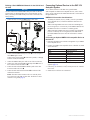
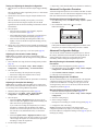
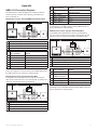
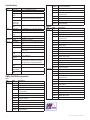
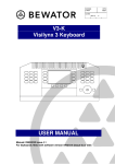
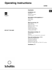
Important Safety Information GHP™ 10V Installation Instructions To obtain the best possible performance and to avoid damage to your boat, install the Garmin® GHP 10V marine autopilot system according to the following instructions. Professional installation of the autopilot system is highly recommended. The GHP 10V is compatible with C3 or newer Volvo® EVC systems. Contact Volvo for more information on updating older EVC systems. Read all installation instructions before proceeding with the installation. If you experience difficulty during the installation, contact Garmin Product Support. NOTE: There is an installation checklist on the last page of these instructions. Remove the last page and refer to the checklist as you proceed through the GHP 10V installation. Warnings You are responsible for the safe and prudent operation of your vessel. The GHP 10V is a tool that will enhance your capability to operate your boat. It does not relieve you from the responsibility of safely operating your boat. Avoid navigational hazards and never leave the helm unattended. Always be prepared to promptly regain manual control of your boat. Learn to operate the GHP 10V on calm and hazard-free open water. Use caution when operating the GHP 10V near hazards in the water, such as docks, pilings, and other boats. See the Important Safety and Product Information guide in the product box for product warnings and other important information. caution Equipment to be connected to this product should have a fire enclosure or be provided with a fire enclosure. Registering Your Device Always wear safety goggles, ear protection, and a dust mask when drilling, cutting, or sanding. • Go to http://my.garmin.com. • Keep the original sales receipt, or a photocopy, in a safe place. For future reference, write the serial number assigned to each component of your GHP 10V system in the spaces provided on page 3. The serial numbers are located on a sticker on each component. Notice When drilling or cutting, always check the opposite side of the surface. Be aware of fuel tanks, electrical cables, and hydraulic hoses. Help us better support you by completing our online registration today. Contacting Garmin Contact Garmin Product Support if you have any questions while using your GHP 10V. In the USA, go to www.garmin.com/support, or contact Garmin USA by phone at (913) 397.8200 or (800) 800.1020. In the UK, contact Garmin (Europe) Ltd. by phone at 0808 2380000. In Europe, go to www.garmin.com/support and click Contact Support for in-country support information, or contact Garmin (Europe) Ltd. by phone at +44 (0) 870.8501241. GHP 10V Installation Instructions 1 Table of Contents GHP™ 10V Installation Instructions................................. 1 Registering Your Device.............................................................. 1 Contacting Garmin...................................................................... 1 Important Safety Information....................................................... 1 GHP 10V Package Contents and Needed Tools............ 3 Main Components....................................................................... 3 Configuring the GHP 10V............................................... 11 About the Sea Trial Wizard.........................................................11 Important Sea Trial Wizard Considerations................................11 Starting the Sea Trial Wizard......................................................11 Performing the Sea Trial Wizard................................................11 Configuring the Planing RPM.......................................................... 11 Calibrating the Compass................................................................. 11 Performing the Autotune Procedure................................................ 11 Setting North.................................................................................... 11 Setting the Fine Heading Adjustment.............................................. 11 CCU...................................................................................................3 Autopilot Gateway..............................................................................3 GHC 20..............................................................................................3 Evaluating the Results of the Autopilot Configuration................11 CCU Interconnect Cable....................................................................3 Alarm.................................................................................................3 GHC 20 NMEA 0183 Data Cable.......................................................3 NMEA 2000 Cables and Connectors.................................................4 Advanced Configuration Procedure.......................................... 12 Installation Preparation................................................... 5 Manually Running the Automated Configuration Procedures..........12 Manually Running the Sea Trial Wizard...........................................12 Manually Defining Individual Configuration Settings........................12 Cables and Connectors............................................................... 3 Tools Needed.............................................................................. 4 Mounting and Connection Considerations.................................. 5 CCU Mounting Considerations..........................................................5 CCU Connection Considerations.......................................................5 Alarm Mounting Considerations . ......................................................5 Alarm Connection Considerations.....................................................5 NMEA 2000 Connection Considerations...........................................5 GHC 20 Mounting Considerations.....................................................5 GHC 20 Connection Considerations..................................................5 Installation Procedures.................................................... 7 CCU Installation.......................................................................... 7 Installing the CCU Mounting Bracket.................................................7 Securing the CCU in the CCU Bracket..............................................7 Connecting the CCU..........................................................................7 Alarm Installation...............................................................................7 Mounting the Alarm............................................................................7 Connecting the Alarm........................................................................7 Testing and Adjusting the Autopilot Configuration............................12 Adjusting the Acceleration Limiter Settings......................................12 Adjusting the Autopilot Gain Settings...............................................12 Enabling the Advanced Configuration Procedure............................12 Advanced Configuration Settings.............................................. 12 Appendix......................................................................... 13 NMEA 0183 Connection Diagrams............................................ 13 Specifications............................................................................ 14 NMEA 2000 PGN Information................................................... 14 CCU.................................................................................................14 GHC 20............................................................................................14 NMEA 0183 Information............................................................ 15 GHP 10V Configuration Settings............................................... 15 Error and Warning Messages.................................................... 16 CCU Mounting Template........................................................... 17 GHP 10V Installation Checklist.................................................. 19 Autopilot Gateway Installation..................................................... 7 Mounting the Autopilot Gateway........................................................7 Connecting the Autopilot Gateway.....................................................8 GHC 20 Installation..................................................................... 8 Mounting the GHC 20........................................................................8 Connecting the GHC 20.....................................................................8 Multiple GHC 20 Considerations.......................................................8 Connecting the Devices to a NMEA 2000 Network..................... 9 Connecting the GHC 20 to an Existing NMEA 2000 Network............9 Connecting the CCU to an Existing NMEA 2000 Network.................9 Building a Basic NMEA 2000 Network for the GHC 20 and the CCU..............................................................................10 Connecting Optional Devices to the GHP 10V Autopilot System..................................................................... 10 NMEA 0183 Connection Considerations.........................................10 Connecting an Optional NMEA 0183-compatible Device to the GHC 20......................................................................................10 2 GHP 10V Installation Instructions GHP 10V Package Contents and Needed Tools GHC 20 The GHP 10V autopilot system consists of multiple components, each sold separately. Familiarize yourself with all of the components before beginning installation. You must know how the components operate together in order to correctly plan the installation on your boat. As you familiarize yourself with the GHP 10V components, confirm that your package includes the following items. If any parts are missing, contact your Garmin dealer immediately. Record the serial number of each component in the space provided. Main Components The GHP 10V autopilot system consists of three main components, the Course Computer Unit (CCU), the Autopilot Gateway, and the GHC™ 20 user control interface. CCU The GHC 20 is the primary interface used to operate the GHP 10V autopilot system. Using the GHC 20, you engage and steer the GHP 10V. You also set up and customize the GHP 10V using the GHC 20. The GHC 20 connects to a NMEA 2000 network to communicate with the CCU. The GHC 20 also connects with optional NMEA 2000-compatible devices, such as a GPS device, to use advanced features of the GHP 10V. If NMEA 2000-compatible devices are not available, you can connect the GHC 20 to optional NMEA 0183-compatible devices instead. Serial Number Cables and Connectors The CCU acts as the brain of the GHP 10V. The CCU contains the sensory equipment used to determine heading. The CCU connects to the Autopilot Gateway with a single cable. The CCU also connects to a NMEA 2000® network to communicate with the GHC 20, and to optional NMEA 2000-compatible GPS devices (page 9). Serial Number Autopilot Gateway The Autopilot Gateway allows the GHP 10V autopilot system to steer the boat through the Volvo™ steering system. The Autopilot Gateway connects to the CCU through the CCU interconnect cable and connects to the Volvo steering system using a proprietary Volvo connector. The GHP 10V autopilot system includes multiple cables. These cables connect the components to power, to each other, to an alarm, and to optional devices. CCU Interconnect Cable Notice Do not connect this cable to a NMEA 2000 network. This cable connects the CCU to the Autopilot Gateway. A portion of this cable contains color-coded wires with bare ends. These wires connect the CCU to the alarm and to the yellow wire from the GHC 20. Alarm The alarm provides audible alerts from the GHP 10V (page 7). Serial Number GHC 20 NMEA 0183 Data Cable This cable connects the GHC 20 to the yellow wire of the CCU (page 8). This cable can also be used to connect the GHC 20 to optional NMEA 0183-compatible devices (page 10). GHP 10V Installation Instructions 3 NMEA 2000 Cables and Connectors The NMEA 2000 cables connect the CCU and the GHC 20 to the NMEA 2000 network. Either connect the CCU and the GHC 20 to an existing NMEA 2000 network using the included T-connectors and drop cables, or use all of the included NMEA 2000 cables and connectors to build a NMEA 2000 network on your boat if needed (page 9). ➊ ➋ ➌ ➊ ➋ ➌ ➍ ➎ ➍ ➎ Tools Needed • • • • • • • Safety glasses Drill and drill bits 3 1/2 in. (90 mm) hole saw Wire cutters/strippers Phillips and flat screwdrivers Cable ties Waterproof wire connectors (wire nuts) or heat-shrink tubing and a heat gun • Marine sealant • Portable or handheld compass (to test for magnetic interference when determining the best location to install the CCU) • Anti-seize lubricant (optional) Note: Mounting screws are provided for the GHC 20 and the CCU. If the provided screws are not appropriate for the mounting surface, you must provide the correct types of screws. NMEA 2000 drop cable, 6 ft. (2 m) (×2) NMEA 2000 power cable NMEA 2000 T-connector (×3) NMEA 2000 terminator, male NMEA 2000 terminator, female NMEA 2000 Extension Cables NMEA 2000 extension cables are available if needed. Contact your local Garmin dealer or Garmin Product Support for ordering information. 4 GHP 10V Installation Instructions Installation Preparation Before installing the GHP 10V autopilot system, you must plan where all the components will be located on your boat. Temporarily place all the components where you intend to install them. Read these considerations before you begin planning your installation. NOTE: There is an installation checklist on the last page of these instructions. Remove the last page and refer to the checklist as you proceed through the GHP 10V installation. Mounting and Connection Considerations The GHP 10V components connect to each other and to power using the included cables. Ensure that the correct cables reach each component and that each component is in an acceptable location before mounting or connecting any components. CCU Mounting Considerations • The CCU must be mounted in the forward half of the boat, no higher than 10 ft. (3 m) above the waterline. • The CCU must not be mounted in a location where it will be submerged or exposed to wash-down. • The CCU must not be mounted near magnetic material, magnets (speakers and electric motors), or high-current wires. • The CCU must be mounted at least 24 in. (0.6 m) away from movable or changing magnetic disturbances such as anchors, anchor chain, wiper motors, and tool boxes. • A handheld compass should be used to test for magnetic interference in the area where the CCU is to be mounted. If the handheld compass does not point north when you hold it in the location where you intend to mount the CCU, there is magnetic interference. Choose another location, and test again. • The CCU can be mounted below the waterline if it is not in a location where it will be submerged or exposed to wash-down. • The CCU bracket must be mounted on a vertical surface or under a horizontal surface, so that the connected wires hang straight down. • Mounting screws are included with the CCU, but you may need to provide different screws if the supplied screws are not suitable for the mounting surface. CCU Connection Considerations • The CCU interconnect cable connects the CCU to the Autopilot Gateway, and provides 9.5 ft. (3 m) of cable between the CCU and the Autopilot Gateway. ◦◦ If the CCU cannot be mounted within 9.5 ft. (3 m) of the Autopilot Gateway, NMEA 2000 cables can be used to extend the connection. ◦◦ The CCU interconnect cable must not be cut. • The CCU interconnect cable connects the CCU to the GHC 20 with a single yellow signal wire (page 7). The autopilot system does not power on if this connection is not made. GHP 10V Installation Instructions Alarm Mounting Considerations • The alarm should be mounted near the helm station. • The alarm can be mounted under the dashboard. Alarm Connection Considerations • If needed, the alarm wires can be extended with 28 AWG (.08 mm2) wire. NMEA 2000 Connection Considerations • The CCU and the GHC 20 connect to the NMEA 2000 network. If your boat does not have a NMEA 2000 network, one can be built using the included NMEA 2000 cables and connectors (page 10). • To use advanced features of the GHP 10V, optional NMEA 2000-compatible devices, such as a GPS device, can be connected to the NMEA 2000 network. GHC 20 Mounting Considerations Notice The mounting surface must be flat to avoid damaging the device when it is mounted. • The mounting location should provide optimal viewing as you operate your vessel. • The mounting location should allow easy access to the keys on the GHC 20. • The mounting surface must be strong enough to support the weight of the GHC 20 and protect it from excessive vibration or shock. • The area behind the surface must allow room for the routing and connection of the cables. There should be at least a 3-inch (8 cm) clearance behind the case of the GHC 20. • The location must be at least 8 1/4 in. (209 mm) from a magnetic compass, to avoid interference. • The location must be in an area that is not exposed to extreme temperature conditions (page 14). GHC 20 Connection Considerations • You must connect the GHC 20 to the NMEA 2000 network. • For the autopilot to function, you must correctly connect two wires from the GHC 20 data cable: ◦◦ The yellow wire from the GHC 20 data cable must be connected to the yellow wire of the CCU interconnect cable. ◦◦ The black wire from the GHC 20 data cable must be connected to the same ground as the CCU. • Optional NMEA 0183-compatible devices, such as a GPS device, can be connected to the GHC 20 data cable (page 10). 5 ➊ ➋ ➌ ➍ ➎ ➏ ➐ ➑ GHP 10V General Connection Diagram Item ➊ ➋ ➌ ➍ ➎ ➏ ➐ ➑ 6 Description GHC 20 GHC 20 data cable NMEA 2000 network Important Considerations Route the yellow wire to the location where you plan to install the GHC 20 (page 8) The GHC 20 and the CCU must be connected to the NMEA 2000 network using the included T-connectors (page 9). If there is not an existing NMEA 2000 network on your boat, you can build one using the supplied cables and connectors (page 10). NMEA 2000 power cable This cable should be installed only if you are building a NMEA 2000 network. Do not install this cable if there is an existing NMEA 2000 network on your boat (page 10). The NMEA 2000 power cable must be connected to a 9–16 Vdc power source. CCU Mount the CCU with the cables pointing straight down (page 7). CCU power cable The CCU can be connected to a 12-24 Vdc power source. The black wire from the GHC 20 data cable must be connected to the same ground as this cable (page 8). CCU interconnect cable In order for the autopilot to turn on, the yellow wire from this cable must be connected to the yellow wire from the GHC 20 data cable. The orange and blue wires from this cable must be connected to the alarm (page 7). GHP 10V Autopilot Gateway GHP 10V Installation Instructions Installation Procedures After you have completely planned the GHP 10V installation on your boat, and have satisfied all the mounting and connecting considerations for your particular installation, you can begin mounting and connecting the components. CCU Installation To install the CCU, you must mount it to your boat (page 7), connect it to the Autopilot Gateway (page 7), connect it to a NMEA 2000 network (page 9), connect it to the alarm (page 7), and connect it to the yellow CCU signal wire on the GHC 20 (page 7). Installing the CCU Mounting Bracket Before you can mount the CCU, you must select a location and determine the correct mounting hardware (page 5). The CCU bracket has two portions, the mounting portion and the securing portion. 1. Cut out the mounting template provided on page 17. 2. Tape the template to the mounting location. If you are installing the CCU on a vertical surface, install the mounting portion of the bracket with an opening ➊ at the bottom. Connecting the CCU 1. Route the five-pin connector end of the CCU interconnect cable to the location where you plan to access the Volvo multilink bus (page 7). 2. Connect the CCU interconnect cable to the Autopilot Gateway after you have installed the gateway. 3. Route the wires from the bare-wire portion of the cable to the CCU interconnect cable. • Route the orange and blue wires to the location where you plan to install the alarm (page 7). If the cable is not long enough, extend the appropriate wires with 28 AWG (.08 mm2) wire. • Route the yellow wire to the location where you plan to install the GHC 20 (page 8). If the cable is not long enough, extend the yellow wire with 22 AWG (.33 mm2) wire. 4. Route the red and black wires to the battery. This is the primary power input to the CCU. Alarm Installation The alarm audibly alerts you to important GHP 10V events. To install the alarm, you must mount it to your boat (page 7) and connect it to the CCU (page 7). Mounting the Alarm Before you can mount the alarm, you must select a mounting location (page 5). ➋ Secure the alarm with cable ties or other appropriate mounting hardware (not included). ➊ 3. Drill pilot holes at the three mounting locations. 4. Use screws ➋ to secure the mounting portion of the CCU bracket. Securing the CCU in the CCU Bracket 1. Connect the CCU interconnect ➌ cable and the NMEA 2000 drop cable to the CCU. 2. Place the CCU in the mounting portion of the CCU bracket with the wires hanging straight down ➊. 3. Place the securing portion of the bracket over the ball and snap it into the mounting portion of ➋ the bracket, starting with the two arms ➋ that do not have the thumbscrew ➌. ➊ 4. With the cables hanging straight down, connect the arm with the thumbscrew. The cables must hang straight down for the CCU to accurately read your heading. 5. Hand-tighten the thumbscrew until the CCU is held firmly in the bracket. Do not overtighten the thumbscrew. GHP 10V Installation Instructions Connecting the Alarm 1. Route the alarm-cable to the bare-wire end of the CCU interconnect cable. If the cable is not long enough, extend the appropriate wires with 28 AWG (.08 mm2) wire. 2. Connect the cables, based on the table below. Alarm Wire Color White (+) Black (-) CCU Interconnect Cable Wire Color Orange (+) Blue (-) 3. Solder and cover all bare-wire connections. Autopilot Gateway Installation Notice Do not connect the CCU interface connector on either the CCU interconnect cable or the Autopilot Gateway to a NMEA 2000 network. The Autopilot Gateway allows the GHP 10V Autopilot System to communicate with the Volvo EVC system and steer the boat. Mounting the Autopilot Gateway 1. Mount the Autopilot Gateway near the location where you plan to access the Volvo proprietary multilink bus. Ensure the Volvo interface cable reaches the location where you plan to access the Volvo multilink bus. 2. Secure the Autopilot Gateway with cable ties or other appropriate mounting hardware (not included). 7 Connecting the Autopilot Gateway 1. Open the Volvo multilink bus and disconnect the multilink breakout cable. 2. Connect the proprietary Volvo connector ➊ from the Autopilot Gateway to the multilink bus using the included Y-cable. ➊ ➋ 3. Close the Volvo multilink bus. 4. Connect the CCU interface connector ➋ to the CCU cable. GHC 20 Installation Install the GHC 20 by flush-mounting it in the dashboard near the helm, connecting it to the yellow wire from the CCU interconnect cable, and connecting it to a NMEA 2000 network. To use advanced features of the GHP 10V, optional NMEA 2000-compatible or NMEA 0183-compatible devices, such as a GPS device, can be connected to the NMEA 2000 network or connected to the GHC 20 through NMEA 0183. 5. If necessary, use a file and sandpaper to refine the size of the hole. 6. Place the GHC 20 into the cutout to confirm that the four mounting holes are correct. 7. Select an option: • If the mounting holes are correct, proceed to step 8. • If the mounting holes are not correct, mark the correct locations of the four mounting holes. 8. Remove the GHC 20 from the cutout. 9. Drill the four 7/64 in. (2.8 mm) pilot holes. If you are mounting the GHC 20 in fiberglass, use a countersink bit as advised in the notice. 10.Remove the remainder of the template. 11.Place the included gasket on the back of the device and apply marine sealant around the gasket to prevent leakage behind the dashboard. 12.Place the GHC 20 into the cutout. 13.Securely fasten the GHC 20 to the mounting surface using the supplied screws. If you are mounting the GHC 20 in fiberglass, use a anti-galling lubricant as advised in the notice. 14.Snap the decorative bezel ➊ into place. ➊ Mounting the GHC 20 Notice The temperature range for the GHC 20 is from 5°F to 158°F (from -15°C to 70°C). Extended exposure to temperatures outside of this range (in storage or operating conditions) may cause failure of the LCD screen or other components. This type of failure and related consequences are not covered by the manufacturer’s limited warranty. If you are mounting the GHC 20 in fiberglass, when drilling the four pilot holes, it is recommended to use a countersink bit to drill a clearance counterbore through only the top gel-coat layer. This will help to avoid any cracking in the gel-coat layer when the screws are tightened. Stainless-steel screws may bind when screwed into fiberglass and overtightened. Garmin recommends applying an anti-galling, stainless anti-seize lubricant to the screws before installing them. Before you can mount the GHC 20, you must select a mounting location (page 5). 1. Trim the flush-mount template and ensure it will fit in the location where you plan to mount the GHC 20. The flush-mount template is included in the product box, not in these instructions. The flush-mount template has adhesive on the back. 2. Remove the protective liner from the adhesive on the back of the template and apply it to the location where you plan to mount the GHC 20. 3. If you will be cutting the hole with a jigsaw instead of a 317/32 in. (90 mm) hole saw, use a 3/8 in. (10 mm) drill bit to drill a pilot hole as indicated on the template to begin cutting the mounting surface. 4. Using the jigsaw or the 3.5 in. (90 mm) hole saw, cut the mounting surface along the inside of the dashed line indicated on the flushmount template. 8 Connecting the GHC 20 For the autopilot system to function correctly, you must connect two wires from the GHC 20 data cable (yellow and black). 1. Connect the yellow wire from the GHC 20 data cable to the yellow wire from the CCU interconnect cable. If the cable is not long enough, extend the yellow wire with 22 AWG (.33 mm2) wire. 2. Connect the black wire on the GHC 20 data cable to the same ground location as the CCU. If the cable is not long enough, extend the black wire with 22 AWG (.33 mm2) wire. 3. Solder and cover all bare-wire connections. Multiple GHC 20 Considerations You can install multiple GHC 20 devices (sold separately) to control the autopilot from different locations on the boat. • All additional GHC 20 devices must be connected to the NMEA 2000 network (page 9). • To use an additional GHC 20 to turn on the autopilot, connect the yellow and black wires from the additional GHC 20 to the same wires as the primary GHC 20. ◦◦ If you connect additional GHC 20 devices to turn on the autopilot, you must turn them all off to turn off the autopilot. ◦◦ If you do not connect an additional GHC 20 to turn on the autopilot, then the additional GHC 20 enters standby mode when you turn it off, and the autopilot remains on until turned off by the primary GHC 20. GHP 10V Installation Instructions Connecting the Devices to a NMEA 2000 Network Notice If you have an existing NMEA 2000 network on your boat, it should already be connected to power. Do not connect the included NMEA 2000 power cable to an existing NMEA 2000 network, because only one power source should be connected to a NMEA 2000 network. NOTE: In order for the autopilot to turn on, the yellow wire from the GHC 20 data cable be connected to the yellow wire from the CCU interconnect cable, and the black wire from the GHC 20 data cable must be connected to the same ground as the CCU (page 8). Connecting the CCU to an Existing NMEA 2000 Network 1. Determine where to connect the CCU ➊ to your existing NMEA 2000 backbone ➋ (page 5). You can connect the GHC 20 to the CCU through an existing NMEA 2000 network. If you do not have an existing NMEA 2000 network on your boat, all the parts needed to build one are supplied in the GHP 10V package (page 10). ➊ To use advanced features of the GHP 10V, optional NMEA 2000-compatible devices, such as a GPS device, can be connected to the NMEA 2000 network. For more information on NMEA 2000, go to www.garmin.com. Connecting the GHC 20 to an Existing NMEA 2000 Network 1. Determine where to connect the GHC 20 ➊ to your existing NMEA 2000 backbone ➋ (page 5). ➊ ➍ ➌ ➋ ➍ ➌ ➋ 2. Disconnect one side of a NMEA 2000 T-connector from the network. 3. If necessary, to extend the NMEA 2000 network backbone, connect a NMEA 2000 backbone extension cable (not included) to the side of the disconnected T-connector. 4. Add the included T‑connector ➌ for the CCU to the NMEA 2000 backbone by connecting it to the side of the disconnected T‑connector or backbone extension cable. 5. Route the included drop cable ➍ to the bottom of the T-connector added in step 4, and connect it to the T-connector. If the included drop cable is not long enough, you can use a drop cable up to 20 ft. (6 m) long (not included). 6. Connect the drop cable to the to the CCU. 2. Disconnect one side of a NMEA 2000 T-connector from the network. 3. If necessary, to extend the NMEA 2000 network backbone, connect a NMEA 2000 backbone extension cable (not included) to the side of the disconnected T-connector. 4. Add the included T‑connector ➌ for the GHC 20 to the NMEA 2000 backbone by connecting it to the side of the disconnected T‑connector or backbone extension cable. 5. Route the included drop cable ➍ to the bottom of the T-connector added in step 4, and connect it to the T-connector. If the included drop cable is not long enough, you can use a drop cable up to 20 ft. (6 m) long (not included). 6. Connect the drop cable to the to the GHC 20. 7. Connect the drop cable to the T-connector you added in step 3, and to the GHC 20. GHP 10V Installation Instructions 9 Building a Basic NMEA 2000 Network for the GHC 20 and the CCU Notice You must connect the included NMEA 2000 power cable to the boat ignition switch, or through another in-line switch. The GHC 20 will drain your battery if the NMEA 2000 power cable is connected to the battery directly. 1. Connect the three T-connectors ➊ together by their sides. ➏ ➐ ➍ - + ➌ ➊ ➑ To use advanced features of the GHP 10V, optional NMEA 2000-compatible or NMEA 0183-compatible devices, such as a GPS device, can be connected to the NMEA 2000 network or to the GHC 20 through NMEA 0183. NMEA 0183 Connection Considerations • To identify the Transfer (Tx) A(+) and B(-) wires for your NMEA 0183-compatible device, consult the installation instructions for your device. • When connecting NMEA 0183 devices with two transmitting and two receiving lines, it is not necessary for the NMEA 2000 bus and the NMEA 0183 device to connect to a common ground. • When connecting a NMEA 0183 device with only one transmitting (Tx) line or with only one receiving (Rx) line, the NMEA 2000 bus and the NMEA 0183 device must be connected to a common ground. Connecting an Optional NMEA 0183-compatible Device to the GHC 20 1. Determine the NMEA 0183 connection assignments of your NMEA 0183-compatible device. 2. Connect your NMEA 0183-compatible device to the GHC 20, based on the table below. ➎ ➋ ➑ 2. Connect included NMEA 2000 power cable ➋ to a 12 Vdc power source ➌ through a switch. Connect to the ignition switch ➍ of the boat if possible, or through an in-line switch (not included). 3. Connect the NMEA 2000 power cable to one of the T-connectors. 4. Connect one of the included NMEA 2000 drop cables ➎ to one of the T-connectors and to the GHC 20 ➏. 5. Connect the other included NMEA 2000 drop cable to the other T-connector and to the CCU ➐. 6. Connect the male and female terminators ➑ to each end of the combined T-connectors. NOTE: The GHC 20 must connect to the CCU with the yellow CCU signal wire in the GHC 20 data cable. The black wire must connect to CCU ground (page 8). 10 Connecting Optional Devices to the GHP 10V Autopilot System GHC 20 Data Cable Wire Color Black Yellow Blue White Brown Green Function CCU signal ground CCU signal Tx/A (+) Tx/B (-) Rx/A (+) Rx/B (-) Three examples of various connection situations are provided in the appendix (page 13). 3. If necessary, use 22 AWG (.33 mm2) twisted-pair wire for extended runs of wire. 4. Solder and cover all bare-wire connections. GHP 10V Installation Instructions Configuring the GHP 10V The GHP 10V must be configured and tuned to your boat dynamics and motor configuration. Use the Sea Trial Wizard on the GHC 20 to configure the GHP 10V. These wizards will walk you through the necessary configuration steps. About the Sea Trial Wizard The Sea Trial Wizard configures the fundamental sensors on the autopilot, and it is extremely important to complete the wizard in conditions appropriate for your boat. Important Sea Trial Wizard Considerations Complete the Sea Trial Wizard in calm water. The nature of calm water is relative to the size and shape of your boat. • Ensure your boat does not rock while sitting still or moving very slowly. • Ensure your boat is not significantly affected by the wind. • Keep the weight on your boat balanced. DO NOT move around on the boat while completing any of the steps in the Sea Trial Wizard. Starting the Sea Trial Wizard Before you start the Sea Trial Wizard, you must drive to an open area of calm water. 1. Turn on the GHP 10V. 2. Select an option: • If the Sea Trial Wizard starts automatically, proceed to step 3. • If the Sea Trial Wizard does not start automatically, select Menu > Setup > Dealer Autopilot Configuration > Wizards > Sea Trial Wizard. 3. Select Begin. Performing the Sea Trial Wizard 1. 2. 3. 4. 5. 6. 7. Drive your boat to an open area of calm water. Start the Sea Trial Wizard (page 11). Configure the planing RPM (page 11). Calibrate the compass (page 11). Perform the autotune procedure (page 11). Set north (page 11). If necessary, set the fine heading adjustment (page 11). Configuring the Planing RPM 1. Note the RPM reading from the tachometer on the dashboard of your boat at the point your boat transitions from displacement to planing speed. 2. If the tachometer value does not match the value on the GHC 20, use the arrows to adjust the value. 3. Select Done. Calibrating the Compass 1. Drive your boat at slow/idle speed in a straight line. 2. Select Begin, and continue to drive in a straight line. 3. When instructed, turn the boat slowly clockwise, taking care to make the turn as steady and flat as possible. Turn slowly so that the boat DOES NOT list. The GHC 20 displays a completion message when the calibration is complete. GHP 10V Installation Instructions 4. Select an option: • If the calibration completes successfully, select Done. • If the calibration fails, select Retry and repeat steps 1–3. Performing the Autotune Procedure Before you can perform the autotune procedure, you must have a large stretch of open water available. 1. Adjust the throttle so the boat travels below planing speed. 2. Select Begin. The boat performs a number of zigzag motions while the Autotuning is in progress. The GHC 20 displays a completion message. 3. Select an option: • If the autotune completed successfully, select Done and take manual control of the boat. • If the autotune failed, adjust the throttle and select Retry Autotune. 4. If autotune fails, repeat steps 1–3 until the autotune completes successfully. 5. If the autotune procedure continues to fail after you reach maximum cruising speed, reduce your speed to the initial autotune speed and select Alternate Autotune to begin an alternate autotuning procedure. Setting North Before you can set north, you must have at least 45 seconds of hazardfree, open water available. This procedure appears only if you connect an optional GPS device to the GHP 10V (page 10), and the device has acquired a GPS position. If you do not have a GPS device connected, you are prompted to set the fine heading adjustment (page 11). 1. Drive the boat in a straight line at cruising speed, and select Begin. The GHC 20 displays a completion message when the calibration is compete. 2. Select an option: • If the calibration completed successfully, select Done. • If the calibration failed, repeat steps 1–2. Setting the Fine Heading Adjustment This procedure appears only if you do not have an optional GPS device connected to the GHP 10V (page 10). If you do have a GPS device installed on your boat that has acquired a GPS position, are prompted to set north instead (page 11). 1. Using a handheld compass, identify north. 2. Adjust the fine heading setting until it matches north on the magnetic compass. 3. Select Done. Evaluating the Results of the Autopilot Configuration 1. Test the autopilot at a slow speed. 2. If necessary, adjust the gain setting (page 12). 3. Test the autopilot at a higher speed (normal operating conditions). 4. If necessary, adjust the gain and acceleration limiter settings. 11 Testing and Adjusting the Autopilot Configuration 1. Drive the boat in one direction with the autopilot engaged (heading hold). The boat should not oscillate significantly; however, a small amount of oscillation is normal. 2. Turn the boat in one direction using the autopilot and observe the behavior. The boat should turn smoothly, not too quickly or too slowly. When you turn the boat using the autopilot, the boat should approach and settle on the desired heading with minimal overshoot and oscillation. 3. Select an option: • If the boat turns too quickly or too sluggishly, adjust the autopilot acceleration limiter (page 12). • If the heading hold oscillates significantly or the boat does not correct when turning, adjust the autopilot gain (page 12). • If the boat turns smoothly, the heading hold oscillates only slightly or not at all, and the boat adjusts the heading correctly, proceed to step 5. 4. Repeat steps 2 and 3 until the boat turns smoothly the heading hold oscillates only slightly or not at all, and the boat adjusts the heading correctly. 5. For planing vessels, repeat steps 1–4 at faster speeds (page 12). 5. Repeat steps 2 and 3 until the GHP 10V performance is satisfactory. Advanced Configuration Procedure Advanced configuration options are not available on the GHC 20 under normal conditions. To access the advanced configuration settings of the GHP 10V, enable the advanced configuration procedure. Enabling the Advanced Configuration Procedure 1. From the heading screen, select Menu > Setup > System > System Information. 2. Press and hold the center soft key ➊ for 5 seconds. Dealer Mode appears. ➊ 3. Press Back > Back. If the option for Dealer Autopilot Configuration is available on the Setup screen, the advanced configuration procedure is enabled. Advanced Configuration Settings Adjusting the Acceleration Limiter Settings NOTE: When you manually adjust the acceleration limiter, make relatively small adjustments. Test the change before making additional adjustments. You can run the Autotune automated configuration process, calibrate the compass, and define north on the GHP 10V through the GHC 20 without running the wizards. You can also define most settings individually, without running the configuration processes. 1. Turn on the GHP 10V using the advanced configuration procedure (page 12). 2. On the GHC 20V, select Menu > Setup > Dealer Autopilot Configuration > Autopilot Tuning > Acceleration Limiter. 3. Select an option: • Increase the setting if the autopilot turns too quickly, • Decrease the setting if the autopilot turns too slowly. 4. Test the autopilot configuration. 5. Repeat steps 2 and 3 until the GHP 10V performance is satisfactory. Manually Running the Automated Configuration Procedures 1. Enable the advanced configuration procedure (page 12). 2. From the Heading screen, select Menu > Setup > Dealer Autopilot Configuration > Automated Setup. 3. Select Autotune, Calibrate Compass, or Set North. 4. Follow the on-screen instructions. Adjusting the Autopilot Gain Settings NOTE: When you manually adjust the rudder gain (or counter gain), make relatively small adjustments, and adjust only one value at a time. Test the change before making additional adjustments. 1. Enable the advanced configuration procedure (page 12). 2. On the GHC 20, select Menu > Setup > Dealer Autopilot Configuration > Autopilot Tuning > Rudder Gains. 3. Select an option: • Select Low Speed or High Speed and use the arrows on the GHC 20 to adjust how tightly the rudder holds the heading and makes turns at low speed or high speed. If you set this value too high, the autopilot may be overactive, attempting to constantly adjust the heading at the slightest deviation. An overactive autopilot can cause excess wear and tear on the drive unit, and drains the battery at a faster-thannormal rate. • Select Low Speed Counter or High Speed Counter to adjust how tightly the rudder corrects the turn overshoot. If you set this value too high, the autopilot can overshoot the turn again when attempting to counter the original turn. 4. Test the autopilot configuration. 12 Manually Running the Sea Trial Wizard The Sea Trial Wizard allows you to quickly define all of the important configuration settings on the GHP 10V. After running the wizard, if you do not feel the GHP 10V is working correctly, you can run the wizard again at any time. To access the wizard, enable the advanced configuration procedure (page 12). Manually Defining Individual Configuration Settings 1. Enable the advanced configuration procedure (page 12). 2. From the Heading screen, select Menu > Setup > Dealer Autopilot Configuration. 3. Select the a setting category. 4. Select a setting to configure. Descriptions of each setting are available in the appendix (page 15). 5. Configure the value of the setting. NOTE: Configuring certain settings in the dealer autopilot configuration procedure may require you to modify other settings. Review the GHP 10V Configurations Settings section (page 15) prior to modifying any settings. GHP 10V Installation Instructions Appendix NMEA 0183 Connection Diagrams The following three connection diagrams are examples of different situations you may encounter when connecting your NMEA 0183 device to the GHC 20. Example One of Three: Two-way NMEA 0183 Communication ➋ + ➊ ➊ ➋ > > > > ➍ > > If your NMEA 0183-compatible device has only one transmitting wire (Tx), connect it to the brown wire (Rx/A) from the GHC 20, and connect the green wire (Rx/B) from the GHC 20 to NMEA ground. ➋ + ➊ NMEA 0183-Compatible Device Wire Function Power NMEA 0183 ground Rx/A (+) Rx/B (-) Tx/A (+) Tx/B (-) NOTE: When connecting NMEA 0183 devices with two transmitting and two receiving lines, it is not necessary for the NMEA 2000 bus and the NMEA 0183 device to connect to a common ground. Example Two of Three: Only One Receiving Wire If your NMEA 0183-compatible device has only one receiving wire (Rx), connect it to the blue wire (Tx/A) from the GHC 20, and leave the white wire (Tx/B) from the GHC 20 unconnected. ➋ + ➊ > ➍ > > ➊ ➋ ➌ ➍ Example Three of Three: Only One Transmitting Wire GHC 20 NMEA 2000 network (provides power to the GHC 20) 12 VDC power source NMEA 0183-compatible device Wire GHC 20 Wire Color - Function N/A ➊ N/A ➋ Blue - Tx/A (+) ➌ White - Tx/B (-) ➍ Brown - Rx/A (+) ➎ Green - Rx/B (-) ➏ ➌ ➌ ➎ ➏ NMEA 0183-Compatible Device Wire Function Power NMEA 0183 ground Rx N/A Tx/A (+) Tx/B (-) NOTE: When connecting a NMEA 0183 device with only one receiving (Rx) line, the NMEA 2000 bus and the NMEA 0183 device must be connected to a common ground. - ➌ ➍ ➎ ➏ > > ➊ ➋ ➌ ➍ ➌ Wire GHC 20 Wire Color - Function N/A ➊ N/A ➋ Blue - Tx/A (+) ➌ White - unconnected ➍ Brown - Rx/A (+) ➎ Green - Rx/B (-) ➏ > > > ➊ ➋ ➌ ➍ ➌ ➋ ➌ ➍ ➎ - ➊ > > ➍ > GHC 20 NMEA 2000 network (provides power to the GHC 20) 12 VDC power source NMEA 0183-compatible device Wire GHC 20 Wire Color - Function N/A ➊ Green - Rx/B - connect ➋ to NMEA 0183 ground Blue - Tx/A (+) ➌ White - Tx/B (-) ➍ Brown - Rx/A (+) ➎ NMEA 0183-Compatible Device Wire Function Power NMEA 0183 ground Rx/A (+) Rx/B (-) Tx/A (+) NOTE: When connecting a NMEA 0183 device with only one transmitting (Tx) line, the NMEA 2000 bus and the NMEA 0183 device must be connected to a common ground. - ➊ ➋ > ➍ > > GHC 20 NMEA 2000 network (provides power to the GHC 20) 12 VDC power source NMEA 0183-compatible device GHP 10V Installation Instructions 13 Specifications Transmit 059392 ISO Acknowledgment 059904 ISO Request 060928 ISO Address Claim 126208 NMEA - Command/Request/Acknowledge Group Function 126464 Transmit/Receive PGN List Group Function 126996 Product Information 127245 Rudder Data 127250 Vessel Heading PGN Description 059392 ISO Acknowledgment 059904 ISO Request 060928 ISO Address Claim 126208 NMEA - Command/Request/Acknowledge Group Function 126464 Transmit/Receive PGN List Group Function 126996 Product Information 127245 Rudder Data 127250 Vessel Heading 127488 Engine Parameters - Rapid Update 128259 Water Speed 129025 Position - Rapid Update 129029 GNSS Position Data 129283 Cross-Track Error 129284 Navigation Data 129285 Navigation - Route/WP information 130306 Wind Data 130576 Small Craft Status 059392 ISO Acknowledgment 059904 ISO Request 060928 ISO Address Claim NMEA 2000 PGN Information 126208 CCU NMEA - Command/Request/Acknowledge Group Function 126464 Transmit/Receive PGN List Group Function 126996 Product Information 128259 Water Speed 129025 Position - Rapid Update 129026 COG & SOG - Rapid Update 129283 Cross Track Error 129284 Navigation Data 129540 GNSS Sats in View 130306 Wind Data Device CCU Alarm Autopilot Gateway GHC 20 Specification Dimensions Weight Temperature range Case material CCU interconnect cable length NMEA 2000 LEN Dimensions Weight Temperature range Cable length Dimensions Weight Dimensions Weight Cables Measurement 3 19/32 in. diameter (91.4 mm) 5.6 oz. (159 g) From 5°F to 131°F (from -15°C to 55°C) Fully gasketed, high-impact plastic, waterproof to IEC 529 IPX7 standards 16 ft. (5 m) 2 (100 mA) (L × Diameter) 29/32 × 1 in. (23 × 25 mm) 2.4 oz. (68 g) From 5°F to 131°F (from -15°C to 55°C) Type Receive 10 ft. (3.0 m) 51/8 × 23/8 × 1 in. (130 × 60 × 25 mm) Less than 1 oz. (28 g) 4 21/64 × 4 17/32 × 1 3/16 in. (110 × 115 × 30 mm) 8.71 oz. (247 g) NMEA 0183 data cable – 6 ft. (1.8 m) NMEA 2000 drop cable and power cable – 6 1/2 ft. (2 m) From 5°F to 158°F (from -15°C to 70°C) Temperature range Compass-safe 8 1/4 in. (209 mm) distance Material Case: fully-gasketed polycarbonate, waterproof to IEC 60529 IPX7 standards Lens: glass with an anti-glare treatment GHC 20 power 2.5 W max. usage NMEA 2000 9–16 Vdc input voltage NMEA 2000 6 (300 mA) LEN Type PGN Description Receive 059392 ISO Acknowledgment 059904 ISO Request 060928 ISO Address Claim 126208 NMEA - Command/Request/Acknowledge Group Function 14 GHC 20 126464 Transmit/Receive PGN List Group Function 126996 Product Information 127258 Magnetic Variation 127488 Engine Parameters - Rapid Update 129025 Position - Rapid Update 129026 COG & SOG - Rapid Update 129283 Cross Track Error 129284 Navigation Data Transmit The GHP 10V and the GHC 20 are NMEA 2000 certified. GHP 10V Installation Instructions NMEA 0183 Information When connected to optional NMEA 0183-compatible devices, the GHC 20 uses the following NMEA 0183 sentences. Type Receive Transmit Sentence wpl gga grme gsa gsv rmc bod bwc dtm gll rmb vhw mwv xte hdg Category Setting Description Rudder Gains Low Speed Gain Allows you to set the rudder gain for low speeds. This setting applies to the vessel when operating below planing speed. If you set this value too high, the autopilot may be overactive, attempting to constantly adjust the heading at the slightest deviation. An overactive autopilot can cause excess wear and tear on the drive unit (page 12). Rudder Gains Low Speed Counter Allows you to set the rudder gain counter-correction for low speeds. This setting applies to the vessel when operating below planing speed. If you set this value too high, the autopilot may be overactive, attempting to constantly adjust the heading at the slightest deviation. An overactive autopilot can cause excess wear and tear on the drive unit (page 12). Rudder Gains High Speed Gain Allows you to set the rudder gain for high speeds. This setting applies to the vessel when operating above planing speed. If you set this value too high, the autopilot may be overactive, attempting to constantly adjust the heading at the slightest deviation. An overactive autopilot can cause excess wear and tear on the drive unit (page 12). Rudder Gains High Speed Counter Allows you to set the rudder gain counter-correction for high speeds. This setting applies to the vessel when operating above planing speed. If you set this value too high, the autopilot may be overactive, attempting to constantly adjust the heading at the slightest deviation. An overactive autopilot can cause excess wear and tear on the drive unit (page 12). NMEA Setup NMEA Checksum If the connected NMEA 0183 GPS unit incorrectly calculates checksums, you may still be able to use it if you turn this setting off. When set to off, data integrity is compromised. GHP 10V Configuration Settings Although all of the configuration is typically completed automatically through wizard, you can manually adjust any setting (page 12). NOTE: Depending upon the configuration of the autopilot, certain settings may not appear. Category Setting Description Speed Source Setup Verify Tachometer Allows you to compare the RPM readings on the GHC 20 with the tachometers on the dashboard of your boat. Speed Source Setup Planing RPM Allows you to adjust the RPM reading on the GHC 20 at the point your boat transitions from displacement to planing speed. If the value does not match the value on the GHC 20, use the arrows to adjust the value. Speed Source Setup Low RPM Limit Allows you to adjust lowest RPM point of your boat. If the value does not match the value on the GHC 20, use the arrows to adjust the value. Speed Source Setup High RPM Limit Allows you to adjust the highest RPM point of your boat. If the value does not match the value on the GHC 20, use the arrows to adjust the value. GHP 10V Installation Instructions 15 Category Setting NMEA Setup Reversed XTE If the connected NMEA 0183 GPS unit sends the incorrect steering direction with the cross track error signal. You can use this setting to correct the steering direction. Navigation Setup Navigation Gain Navigation Setup Navigation Trim Gain Description Allows you to adjust how aggressively the autopilot eliminates cross-track error while following a Route-To pattern. If this value is too high, the autopilot can oscillate back and forth across the course line over long distances. If this value is too low, the autopilot may respond slowly in eliminating cross-track error. Error and Warning Messages Error Message Autopilot is not receiving navigation data. Autopilot placed in heading hold. Connection with autopilot lost Low GHC supply voltage Cause The autopilot is no longer receiving valid navigation data while performing a Route-To. This message will also be shown if navigation is stopped on a chartplotter prior to disengaging the autopilot. The GHC lost connection with CCU. The supply voltage level is below the value specified in the low voltage alarm menu. Autopilot Action • Alarm sounds • Autopilot transitions to heading hold N/A N/A Allows you to adjust the acceptable amount of long term cross-track error while following a Route-To pattern. Only adjust this setting after the navigation gain has been set. If this value is too high, the autopilot will overcompensate for crosstrack error. If this value is too low, the autopilot will allow a large long term cross-track error. NOTE: Advanced configuration settings are available when using the advanced configuration procedure (page 12). Other settings are available during normal operation of the GHP 10V. See the configuration section of the GHC 20 Owner’s Manual for more information. 16 GHP 10V Installation Instructions CCU Mounting Template ➊ ➊ Up, when installing on a vertical surface GHP 10V Installation Instructions 17 GHP 10V Installation Checklist Detach this checklist from the installation instructions and use it to assist with the GHP 10V installation process. Read all installation instructions before installing the GHP 10V. Contact Garmin Product Support if you have any questions during the installation process. 1. Refer to the diagram and notes starting on page 6 to understand the necessary electrical and data connections. 2. Lay out all of the components first. Check the cable lengths. Obtain extensions if necessary. 3. Mount the CCU by following the directions starting on page 5. Mount the CCU in a location free of magnetic interference. Use a handheld compass to test for magnetic interference in the area. Mount the CCU in the bracket so that the wires hang straight down. 4. Mount the GHC 20 by following the directions starting on page 5. 5. Mount the Autopilot Gateway by following the directions on page 7. 6. Connect the Autopilot Gateway to the Volvo multilink bus (page 8). 7. Connect the Autopilot Gateway to the CCU using the CCU interconnect cable (page 8). 8. Connect the GHC 20 and the CCU to a NMEA 2000 network. Connect an optional NMEA 2000‑compatible GPS device to the NMEA 2000 network (page 9). 9. Connect the yellow wire on the GHC 20 data cable to the yellow CCU signal wire on the CCU interconnect cable and the black wire on the GHC 20 data cable to CCU ground. Connect an optional NMEA 0183-compatible GPS device to the GHC 20 if a NMEA 2000‑compatible GPS device is not available (page 10). 10. Configure the GHP 10V system by completing the Sea Trial Wizard (page 11). GHP 10V Installation Instructions 19 © 2013 Garmin Ltd. or its subsidiaries All rights reserved. Except as expressly provided herein, no part of this manual may be reproduced, copied, transmitted, disseminated, downloaded or stored in any storage medium, for any purpose without the express prior written consent of Garmin. Garmin hereby grants permission to download a single copy of this manual onto a hard drive or other electronic storage medium to be viewed and to print one copy of this manual or of any revision hereto, provided that such electronic or printed copy of this manual must contain the complete text of this copyright notice and provided further that any unauthorized commercial distribution of this manual or any revision hereto is strictly prohibited. Information in this document is subject to change without notice. Garmin reserves the right to change or improve its products and to make changes in the content without obligation to notify any person or organization of such changes or improvements. Visit the Garmin Web site (www.garmin.com) for current updates and supplemental information concerning the use and operation of this and other Garmin products. Garmin®, the Garmin logo, and GPSMAP® are registered trademarks of Garmin Ltd. or its subsidiaries, registered in the USA and other countries. GHP™, GHC™, and myGarmin™ are trademarks of Garmin Ltd. or its subsidiaries. These trademarks may not be used without the express permission of Garmin. Volvo® is a registered trademark of Volvo Trademark Holding AB. NMEA 2000® is a registered trademark of the National Marine Electronics Association. Loctite® and Pro Lock Tight® are registered trademarks of Henkel Corporation. For the latest free software updates (excluding map data) throughout the life of your Garmin products, visit the Garmin Web site at www.garmin.com. © 2013 Garmin Ltd. or its subsidiaries Garmin International, Inc. 1200 East 151st Street, Olathe, Kansas 66062, USA Garmin (Europe) Ltd. Liberty House, Hounsdown Business Park, Southampton, Hampshire, SO40 9LR UK Garmin Corporation No. 68, Zhangshu 2nd Road, Xizhi Dist., New Taipei City, 221, Taiwan (R.O.C.) www.garmin.com April 2013 190-01334-10_0A Printed in Taiwan