1
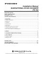
Installation Manual
NAVIGATIONAL ECHO SOUNDER
FE-700
IMPORTANT NOTICE ......................................................................................................i
SAFETY INSTRUCTIONS...............................................................................................ii
EQUIPMENT LISTS .......................................................................................................iii
SYSTEM CONFIGURATION ..........................................................................................iv
1. MOUNTING .................................................................................................................1
1.1 Category of Equipment ........................................................................................................................... 1
1.2 Display Unit ............................................................................................................................................. 1
1.3 Transducer .............................................................................................................................................. 4
1.4 Distribution Box ....................................................................................................................................... 6
1.5 Matching Box .......................................................................................................................................... 7
1.6 Digital Depth Indicator FE-720 (option)................................................................................................... 7
1.7 Transducer Switch Box EX-8 (option) ..................................................................................................... 9
1.8 Gate Valve GV-50B-6B, GV-200B-8B (option)........................................................................................ 9
2. WIRING ..................................................................................................................... 11
3. CHANGING POWER SPECIFICATIONS ..................................................................20
4. ADJUSTMENTS ........................................................................................................22
4.1 Transducer Setting ................................................................................................................................ 22
4.2 Setting the Time .................................................................................................................................... 24
PACKING LISTS………………………………………………… .......................…………A-1
OUTLINE DRAWINGS…………………………………………… ...................…………..D-1
INTERCONNECTION DIAGRAMS…………………………… ................... …………….S-1
www.furuno.co.jp
All brand and product names are trademarks, registered trademarks or service marks of their respective holders.
i
The paper used in this manual
is elemental chlorine free.
・FURUNO Authorized Distributor/Dealer
9-52 Ashihara-cho,
Nishinomiya, 662-8580, JAPAN
Telephone : +81-(0)798-65-2111
Fax
: +81-(0)798-65-4200
All rights reserved.
Printed in Japan
A : JAN . 2000
Q : JUL . 24, 2009
Pub. No. IME-23660-Q
(DAMI )
FE-700
*00080891011*
*00080891011*
* 0 0 0 8 0 8 9 1 0 1 1 *
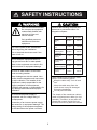
SAFETY INSTRUCTIONS
WARNING
CAUTION
ELECTRICAL SHOCK HAZARD
Observe the following compass safe
distances to prevent deviation of a
magnetic compass:
Do not open the equipment
unless totally familiar with
electrical circuits and
service manual.
Standard
compass
Only qualified personnel
should work inside the
equipment.
Steering
compass
Display
unit
0.50 m
0.40 m
Distribution
Box
1.90 m
1.15 m
Matching Box
0.50 m
0.40 m
Transducer
Switch Box
(option)
1.00 m
0.60 m
Do not install the equipment where it
may get wet from rain or water splash.
Junction Box
(option)
0.30 m
0.30 m
Water in the equipment can result in fire,
electrical shock or equipment damage.
Digital depth
indicator (option)
0.50 m
0.40 m
Distribution box
(option)
0.30 m
0.30 m
Turn off the power at the switchboard
before beginning the installation.
Fire or electrical shock can result if the
power is left on.
Be sure no water leaks in at the transducer mounting location.
Water leakage can sink the vessel. Also
confirm that the transducer will not loosen
by ship’s vibration. The installer of the
equipment is solely responsible for the
proper installation of the equipment.
FURUNO will assume no responsibility for
any damage associated with improper
installation.
When handling the transducer cable,
keep in mind following points.
Keep the cable away from oil and
fuel.
Keep the cable away from the
place where it may be damaged
during the installation.
Do not paint the cable.
Be sure that the power supply is
compatible with the voltage rating of
the equipment.
The sheath of the transducer cable is
made of chlorophrene rubber (or vinyl
chloride). Therefore, do not paint the
sheath with organic liquid (such as
toluene) since it may harm the sheath.
Connection of an incorrect power supply
can cause fire or equipment damage. The
voltage rating of the equipment appears
on the label above the power connector.
i
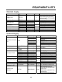
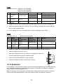
EQUIPMENT LISTS
Standard Supply
Name
Type
Display Unit
FE-701
Distribution Box
FE-702
MB-502
MB-504
50B-6B
200B-8B
TTF-5600
TTF-2000
SP02-04101
CP02-06301
Matching Box
Transducer
Transducer Tank
Spare Parts
Installation Materials
Code no.
Qty
-
1
000-013-602
000-013-604
000-015-586
000-015-587
001-228-890
001-228-950
1
Remarks
w/Installation Materials
CP02-06400 (000-015-872)
and Accessories FP02-04800
(000-015-469)
1
1
1
1 set
1 set
For 50B-6B
For 200B-8B
w/15 m or 30 m cable
w/15 m, 30 m or 50 m cable
For 50B-6B
For 200B-8B
For distribution box
For distribution box
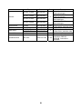
Optional Supply
Name
Type
Code no.
000-012-179
Qty
000-012-176
Transducer Switch
Box
EX-8
Cable Assy.
FM-C6FPS003020
JUNCTION Box
JIS F8821-1MO
0-20A3P
TTF-5001
TTF-2001
Transducer Tank
TTF-5002
TTF-2002
OP02-78-1
Bulkhead Kit
OP02-78-2
OP02-79-1
Flush Mount Kit (F) OP02-79-2
OP02-79-3
Flush Mount Kit (S) OP02-80
Data Recording
02-522-990
Software for PC
Digital Depth
Indicator
FE-720
1
000-012-183
000-012-182
000-012-180
000-012-181
000-143-821
1
000-804-877
1
000-015-877
000-015-878
000-015-885
000-015-887
001-229-270
001-229-280
001-229-290
001-229-300
001-229-310
001-229-320
001-229-090
000-029-025
ii
1
1
1
Remarks
Flush mount, color specified
Bulkhead mount, color
specified
7.5BG7/2, Flush mount
7.5BG7/2, Bulkhead mount
N.G, Flush mount
N.G, Bulkhead mount
2 m cable w/ a 6P connector
For EX-8
For 50B-6B
For 200B-8B
For 50B-6B (w/Flange)
For 200B-8B (w/Flange)
2.5GY5/1.5
7.5BG7/2
N3.0
2.5GY5/1.5
7.5BG7/2
1
1
1 set
For Windows 95/98/NT4.0
w/Installation Materials
CP02-06700 (000-029-068)
Spare Parts
SP65-00601 (002-889-730)
Accessories
FP65-00400 (000-029-067)
Name
Type
Code no.
MF-22L-1-100V
000-069-401
MF-22L-1-200V
000-069-403
Dimmer
Qty
1
MF-22L-2-100V
000-069-402
MF-22L-2-200V
000-069-404
Terminal Box
DS-802
000-029-064
1 set
EGC Printer
PP-505-FE
GV-50B-6B
GV-200B-8B
AU-12
000-055-892
000-015-265
000-015-273
-
1 set
Gate Valve
Alarm Unit
Distribution Box
MB-1200
000-016-185
iii
1
Remarks
100 VAC-120 VAC,
Flush mount type
200 VAC-240 VAC,
Flush mount type
100 VAC-120 VAC,
Bulk head type
200 VAC-240 VAC,
Bulk head type
With Installation Materials
CP65-00903 (000-029-064)
With Installation Materials
CP02-07601 (002-891-620)
1
1 set
For connection of
transducer 50B-6B,
200B-8B, instructions
included.
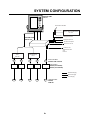
SYSTEM CONFIGURATION
DISPLAY UNIT
FE-701
Terminal Box DS-802
IEC 61162-1 DIGITAL DEPTH INDICATOR
FE-720
IEC 61162-1
DISTRIBUTION
BOX FE-702
Navigation Device
IEC 61162-1
Navigation Device
EIA-232C
Personal Computer
Contact signal
Alarm Unit AU-12
100/110-115/
200/220-230 VAC
and
DC24 V
DISTRIBUTION
BOX
MB-1200
JB
JB
SWITCH BOX
EX-8
JB
JB
JB
JUNCTION BOX
JISF8821-1M0 0-20A3P
Matching Box
MB-502 (For 50B-6B)
MB-504 (For 200B-8B)
: Standard Supply
: Optional Supply
: Local Supply
TRANSDUCER
50B-6B,
200B-8B
iv
1. MOUNTING
NOTICE
Do not apply paint, anti-corrosive sealant
or contact spray to coating or plastic
parts of the equipment.
Those items contain organic solvents that
can damage coating and plastic parts,
especially plastic connectors.
1.1 Category of Equipment
Equipment for protected area
• Display Unit
• Distribution Box
• Matching Box
• Transducer Switch Box (option)
• Digital Depth Indicator (option)
Equipment to be submerged
• Transducer
1.2 Display Unit
1.2.1 Mounting consideration
The display unit can be installed on a tabletop, on the overhead, on the bulkhead or flush
mounted in a console or panel.
When selecting a mounting location for the display unit keep the following in mind.
• Keep the display unit out of direct sunlight.
• The temperature and humidity should be moderate and stable.
• Locate the unit away from exhaust pipes and vents.
• The mounting location should be well ventilated.
1
• Mount the unit where shock and vibration are minimal.
• Keep the unit away from electromagnetic field-generating equipment such as motors and
generators.
• For maintenance and checking purposes, leave sufficient space at the sides and rear of the
unit and leave slack in cables.
• A magnetic compass will be affected if placed too close to the display unit. Observe the
following compass safe distances to prevent disturbance to the magnetic compass.
Standard compass: 0.50 meters
Steering compass: 0.40 meters
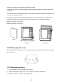
Cover
Desktop
Overhead
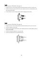
1.2.2 Removing the cover
While pressing the center of the cover with your thumbs as illustrated, pull the cover towards
you to remove it.
1.2.3 Desktop mounting
1.
Fix the hanger with four tapping screws (5x20).
2.
Screw knob bolts in display unit, set it to hanger, and tighten knob bolts.
3.
Attach the dummy covers to the unused holes.
2
Dummy cover
5x20 tapping screws
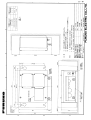
1.2.4
Flush mounting
There are two types of flush mount kits, F type and S type. For details, see the outline diagrams
at the back of this manual.
3
F type
Flush Mount Kit (F): OP02-79-1 (001-229-290)
OP02-79-2 (001-229-300)
OP02-79-3 (001-229-310)
No. Name
Type
Code no.
100-279-270
Cosmetic
1
02-129-1041-0
100-279-280
panel
100-279-290
000-162-897-1
2
Hex bolt
M6x12
0
Spring
000-158-855-1
3
M6
washer
0
Qty
1
Remarks
OP02-79-1:N3.0
OP02-79-2:2.5GY5/1.5
OP02-79-3:7.5GY7/2
4
4
1. Prepare a cutout in the mounting location whose dimensions are 210 (W) x 194 (H) mm.
2. Attach the cosmetic panel (02-129-1041-0) to the display unit with four hex bolts (M6x12)
and four spring washers (M6).
3. Fix the display unit to the mounting location with four tapping screws (5x20).
S type
Flush Mount Kit (S):
OP02-80 (001-229-320)
No.
1
2
Name
Type
Fixing plate 02-129-1045-0
Wing bolt
M4x30
3
Hex bolt
4
5
Spring
washer
Wing nut
M6x12
M6
M4
Code no.
100-279-300
000-804-799
000-162-897-1
0
000-158-855-1
0
000-863-306
Qty
2
6
Remarks
4
4
6
1.
Prepare a cutout in the mounting location whose dimensions are 194 x 194 mm.
2.
Insert the display unit to the cutout.
3.
Attach two fixing plates (02-129-1045-0) to the display unit with four
hex bolts (M6x12) and spring four washers (M6).
4.
Screw six wing bolts (M4x30) to wing nuts (M4).
5.
Fasten the display unit with six wing bolts and nuts.
1.3 Transducer
The installation of the transducer and the tank should be accomplished by a dockyard referring
to the installation drawings at the back of this manual. An example of transducer installation
method is also shown in paragraph 1.3.2.
Note: Discussions should take place and agreement reached with the dockyard for sufficient
reinforcement and watertightness of the hull to comply with the regulations concerned.
4
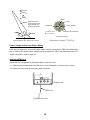
1.3.1 Mounting Location
To decide the location of the transducer, the following points should be taken into account.
• The most important matter is where the transducer is installed. The position should be free
from aeration possibly occurring beneath the hull and also not affected by engine and
propeller noise.
• It is known that air bubble streams start approximately from a quarter length from the bow,
and spreads over the hull bottom approximately to three quarters. Air bubble streams vary in
form and intensity according to ship's speed, draught, trim, shape of bow and hull, as well as
sea state.
• In a laden ship, a position somewhere near a quarter of the ship's length from the stern often
gives satisfactory results. As for vessels such as oil tankers whose fore draught is especially
shallow, an after position about three quarters of ship's length from the stern is often
suitable.
• It is recommended to install the transducer on the keel line or between 600 mm and 900 mm
from the keel to minimize the effect of aerated water.
• Sitting near obstructions such as the forward propeller, bow thruster, water intake pipes and
speed log sensor should be avoided.
• Select a place giving minimum mechanical vibration.
• Do not lay the transducer cable near or in parallel with other electric cables.
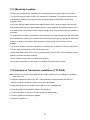
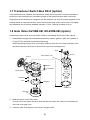
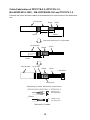
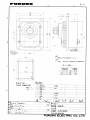
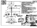
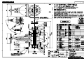
1.3.2 Example of Transducer Installation (TTF-5600)
Note: Never fail to remove the transducer and rubber gasket prior to welding the transducer
tank to the hull.
1. Install the transducer tank on the hull. The tank bottom should be flush with the hull
bottom. Feed the transducer cable through the cable gland.
2. Apply sealing tape to the threads of the gland nut for watertightness.
3. Pass the cable thru the gasket, washer and gland nut.
4. Fix the transducer to the tank with the transducer fixing flange.
5. Coat the gland nut with silicone grease.
6. Tighten the gland nut.
5
7. It is recommended to enclose the transducer cable in a conduit pipe for waterproofness
and electrical shielding as well as for protecting the cable from mechanical damage.
The conduit pipe should be fixed to the flange on the transducer tank. The pipe should
be of such a length to clear the water level when the ship is fully loaded. The pipe end
should be finished with filling compound. It is recommended to fill the pipe with sand
between the transducer and the junction box (or matching box). This will protect the
transducer from vibration and damage.
SGP 11/4"
90
K
7
*
59
*
1
2
3
4
5
6
7
8
JIS B2221 5 -32
4- 15
FIXING HOLE
154
115
Transducer (50B-6B)
Transducer Tank
Fixing Flange
Gland Nut
Washer
Rubber Gasket
Hex. Bolt (M6x25)
Spring Washer (For M6)
*Sea water comes into the area marked
with "*" inside the tank.
70
FLUSH FINISH
190.7+3
DOUBLING PLATE
(SHIPPING SUPPLY)
HULL PLATE
Transducer Tank for 50B-6B Transducer
1.4 Distribution Box
A magnetic compass will be affected if placed too close to the distribution box. Observe the
following compass safe distance to prevent disturbance to the magnetic compass.
Standard compass: 1.90 meters
Steering compass: 1.15 meters
Fasten the distribution box with four tapping screws (6x30) referring to the outline drawing at the
end of this manual.
6
1.5 Matching Box
The matching box should be selected depending on the transducer type;
• 50B-6B transducer: MB-502
• 200B-8B transducer: MB-504
Fasten the matching box with four Trapping screws (6x20: local supply). Compass safe
distances are as follows; standard compass: 0.50 m, Steering compass: 0.40 m.
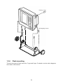
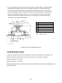
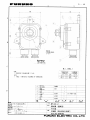
1.6 Digital Depth Indicator FE-720 (option)
The indicator can be installed on a tabletop, on the overhead. Refer to outline drawings at the
end of this manual for installation instructions. When selecting a mounting location, keep in mind
the following points:
• Locate the unit away from exhaust pipes and vents.
• The mounting location should be well ventilated.
• Mount the unit where shock and vibration are minimal.
• Locate the unit away from equipment which generates electromagnetic fields such as a
motor or generator.
• Allow sufficient maintenance space at the sides and rear of the unit and leave sufficient slack
in cables, to facilitate maintenance and servicing.
• Observe the following compass safe distances to prevent deviation of a magnetic compass.
Standard compass: 0.50 m, Steering compass: 0.40 m.
1. Fasten the hanger with four self-tapping screws (5x20).
2. Fasten the digital depth indicator to the hanger with two knobs.
Tabletop
Overhead
■ Flush mounting
There are two types of flush mount kits, F type and S type. For details, see the outline diagrams
at the back of this manual.
7
F type
Use the accessories FP65-00401 (See page A-7).
1. Prepare a cutout in the mounting location whose dimensions are 183 (W) x 92 (H) mm.
2. Attach the cosmetic panel (20-016-1051) to the indicator with two hex bolts (M6x12) and
two spring washers (M6).
3. Fix the indicator to the mounting location with four tapping screws (5x20).
S type
Use the accessories FP65-00402 (See page A-8).
1. Prepare a cutout in the mounting location whose dimensions are 167 (w) x 92 (H) mm.
2. Insert the indicator to the cutout.
3. Attach two fixing plates (20-007-2401) to the indicator with two hex bolts (M6x12) and two
spring washers (M6).
4. Screw four wing bolts (M4x30) to wing nuts (M4).
5. Fasten the indicator with four wing bolts and nuts.
8
1.7 Transducer Switch Box EX-8 (option)
If two transducers are installed, the transducers switch box is required. Locate the transducer
switch box near the display unit considering length of the interconnection cable. Select the
bright place where the panel of equipment can be watched. Use only the screws supplied on the
terminal inside to make connections. Use of other screws may cause a short circuit. Compass
safe distances are as follows; standard compass: 1.00 m, Steering compass: 0.60 m.
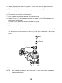
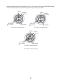
1.8 Gate Valve GV-50B-6B, GV-200B-8B (option)
Assemble the Gate Valve as shown below. Refer to the drawing at the end of this manual.
1. Disassemble the gate valve assembled tentatively: spacer, gasket1, gate valve, gasket 2,
O-ring (P170), seachest cap and shaft assembly.
When assembling the gate valve, use original washers, bolts and nuts. Keep the bottom of the
seachest cap and the shaft free of dust and be careful not to damage them.
BOLT
SCALE
NUT
WASHER
GATE VALVE
1
O-RING
(P135)
O-RING
(P170)
WASHER
NUT
SHAFT
SEACHEST CAP
GASKET1
GASKET2
SPACER
2. Weld the spacer to the hull bottom.
The hull side of the spacer should be flush with the hull bottom. Be careful not to damage the
side fixed to the gate valve.
3. Clean the side of the spacer to be fixed to the gate valve.
9
4. Grease (supplied) both sides of the gasket 1 and the inner side of the spacer. Place the
gasket 1 onto the spacer.
5. Clean the flange side of the gate valve, and place it on the gasket 1. The scale side of the
gate valve should be up.
6. Fix stud bolts with washers and bolts loosely.
7. Keep seachest cap and shaft assembly free of dirt and dust.
8. Grease O-ring (P170) and seachest cap lightly, and attach O-ring (P170) and gasket 2 to
the bottom of seachest cap.
O-ring (P170) and gasket 2 are attached by adhesion of grease.
9. Place the assembly made at step 8 on the gate valve.
10. Fix the assembly with bolts, nuts and washers loosely.
11. Unscrew nuts from flange 2, and confirm that shaft can be moved up and down smoothly by
hand.
You will feel some resistance because of the O-ring (P135). (See the illustration on the previous
page.)
Nut
Washer
Flange 2
12. Fasten the gate valve with bolts, nuts and washers above and below.
NOTE)
When installing a transducer, do it before step 7 or after removing the seachest cap
and the shaft assembly.
10
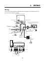
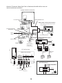
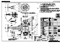
2. WIRING
Wiring
Connect three cable assemblies (supplied) between the display unit and distribution box. See
the interconnection diagram for details.
Display unit FE-701 (rear panel)
FM-C6FPS002-100
MJ-A3SPF0015-100C
POWER
DATA
XDR
Digital depth indicator FE-720 (option)
When silencing the alarm beep, connect
to *2 connector.
2.0 sq
Personal computer
(EIA-232C)
TTYCYS-4
MJ-A10SPF0002-100
Terminal
Box
Ship's DPYCYS-1.5
mains
*2
*1
1.25 sq
MJ-A7SPF0009-020C
*1
Distribution box FE-702
2.0 sq
Alarm system
DPYCYS-2.5
Navigation
Device
(IEC 61162-1)
Matching box
TB1 TB2
1a 1T
2a 2T
*1: with power
*2: without power
3a 3T
2RNCT-SB
2CX1.5
TB7
FE-702 Top view
CONE board 02P6283
AC
TB5 DC
123 TB6
TB1
TB2
12345678910
12
TB3
12345678910
Transducer
TB4
12345
123
Cable clamp
Ship's
Main
Alarm
System
02S4169
FE-720 FE-720
DPYCYS-2.5
TTYCYS-4
TTYCYS-4
PC IEC
61162-1
TPYCYS-1.5
Power
TTYCYS-4 Sours
for FE-701
11
Ground
When the Transducer Switch Box EX-8 or Distribution Box MB-1200 is used, the
interconnections are as follows.
Display unit FE-701 (rear panel)
MJ-A3SPF0015-100C
FM-C6FPS003-020
POWER
XDR
DATA
Digital depth indicator FE-720 (option)
When silencing the alarm beep, connect
to *2 connector.
2.0 sq
Personal computer
(EIA-232C)
TTYCYS-4
MJ-A10SPF0002-100
Terminal
Box
Ship's DPYCYS-1.5
mains
*2
Ground
1.25 sq
MJ-A7SPF0009-020C
*1
*1
Distribution TRANSDUCER SWITCH BOX *3
EX-8 (option)
box
TB3
FE-702
1 2 3 4 5
2.0 sq
Alarm system
Navigation
Device
(IEC 61162-1)
*1: with power
*2: without power
TB7
FE-702 Top view
RECORDER
TB2
TB1
1 2 3
1 2 3
FORE
TB1
TB2
12345678910
12
AFT
Ground
Matching box
Matching box
TB1 TB2
TB1 TB2
1a 1T
2a 2T
1a 1T
2a 2T
3a 3T
3a 3T
2RNCT-SB
2CX2.5
CONE board 02P6283
AC
TB5 DC
123 TB6
2.0 sq
2RNCT-SB
2CX2.5
TB4
TB3
12345
12345678910
123
Transducer
AFT
Transducer
FORE
Cable clamp
Ship's
Main
Alarm
System
*3: Connection of Distribution Box
MB-1200(option)
FE-720 FE-720
PC IEC
TTYCYS-4
61162-1 TTYCYS-4
TPYCYS-1.5
Power
TTYCYS-4 Source
for FE-701
DISTRIBUTION BOX
MB-1200
TB1
TB2
1 2 3 4 5
2.0 sq
5 2 1 4 3
GND
12
Cable Fabrication of DPYCYS-2.5, DPYCYS-1.5,
MJ-A3SPF0015-100C , FM-C6FPS0002-100 and TPYCYS-1.5
Fabricate the power and other cables as illustrated below to connect them to the Distribution
box.
Vinyl Sheath
Cores
Shield
50mm
40mm
Armor
100mm
Fold back shield over on vinyl sheath.
Vinyl Sheath
Cores
Shield
Cores
Taping
Armor
Vinyl Sheath
Shield
Vinyl Tape
*: See below.
Clamp here.
*: Depending on cables, fabrications are as follows.
DPYCYS-2.5, DPYCYS-1.5, TPYCYS-1.5
Crimp-on lug
FV2-S3.3 Blue
Others
Crimp-on lug
FV1.25-3 Red
Fabrication of cables
13
Several cables are required to supply at local. In this manual, JIS (Japan Industrial Standard )
cables are specified. Use equipment cables refering to the figures below.
Shield
Sheath
Shield Sheath
Armor
Armor
Core
S=1.5 mm 2
=1.56mm
Vinyl sheath
Core
S=2.5 mm 2
=2.01mm
Vinyl sheath
DPYCYS-2.5 sectional view
DPYCYS-1.5 sectional view
Shield Sheath
Armor
Core
S=1.5 mm 2
=1.56mm
Vinyl sheath
TPYCYS-1.5 sectional view
JIS Cables (Cross section)
14
Cable Fabrication of TTYCYS-4
TTYCYS is a Japan Industrial Standard (JIS) cable. Use the equipment one.
Vinyl Sheath
Shield
50mm
Armor
Cores
40mm
100mm
Fold back shield over on vinyl sheath.
Vinyl Sheath
Shield
1
2
Armor
Vinyl Sheath
Taping
Vinyl Tape
Shield
Clamp here.
15
3 mm
2 Rotate
4
Shield
Special tool for
connecting wires,
fitted inside the
Distribution Box
Armor
Conductor
Vinyl sheath
2
1 Insert
3
S =0.75 mm
=1.11 mm
Anticorrosive sheath
(Sectional view)
Terminal Board TB1, TB3 Cross section
Fabrication of cable TTYCYS-4
Power Supply Cable from Ship's Mains
If the ship's mains is AC, the power supply cable must be connected to TB5 in the Distribution
Box. In case of DC ship's mains, cable must be connected to TB6 in the Distribution Box. For
further information, refer to page 16.
Attaching EMI core
Attach EMI core (supplied) to the power cable to prevent noise.
13. Tape the power cable where the EMI core is to be attached, to hold the core in place.
14. Fasten the core close to the power cable connector.
Display unit
EMI core
To distribution box
16
Transducer
Connect the transducer cable to the distribution box. If necessary, attach the junction box
between the distribution box and matching box.
Ground
Connect the ground wire (2.0 sq.) from both the display unit and distribution box to ship’s
ground to prevent interference to the picture. Shorten the ground wire as much as possible.
The optional digital depth indicator FE-720 should be grounded by 1.25 sq. wire.
Note 1: Ground the equipment to prevent mutual interference.
Note 2: Use “closed-type” lugs (supplied) to make the ground connection at the display unit and
distribution box. Do not use an “open-type” lugs.
17
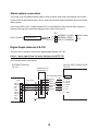
Alarm system connection
The power error and shallow water alarms, which produce audio and visual alarms in the event
of power failure and shallow water, can be output by connecting the distribution box to the ship’s
alarm system.
Connect the DPYCYS-1.5 cable between TB1 in the Distribution Box and the alarm system of
the ship referring to the schematic diagram at the end of this manual.
TB1
Alarm System
1 NORMAL CLOSE
2 NORMAL OPEN
3 RELAY COMMON
DPYCYS-1.5
Select either
one.
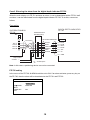
Digital Depth Indicator FE-720
There are two methods to connect the digital depth Indicator FE-720.
Case 1: Input signal from the main display unit to FE-720
The interconnection is as follows.
DIGITAL DEPTH INDICATOR
FE-720
DISTRIBUTION BOX
FE-702
TERMINAL BOX
DS-802(option)
MJ-A7SPF0009-020C
TB3
TD1-A
TD1-B
24V
0V
GND
TD1-A
TD1-B
24V
0V
GND
1
2
3
4
5
6
7
8
9
10
TTYCYS-4
P
P
1
2
3
4
5
6
7
8
WHITE
BLUE
YELLOW
GREEN
RED
BLACK
IN/OUT
<1<
<2<
<3<
<4<
<5<
<6<
TD-A
TD-B
RD-A
RD-B
24V
0V
< 7 < GND
P : Twisted pairs
18
Case2: Silencing the alarm from the digital depth indicator FE-720
When the main display unit FE-701 activates an alarm, it can be deactivated at the FE-701 itself
and also, it can be deactivated from the digital depth indicator FE-720. To do this, connect as
follows.
Connection
DIGITAL DEPTH INDICATOR
FE-720
DISTRIBUTION BOX
FE-702
TB1
TERMINAL BOX
DS-802(option)
1
6
TD1-A 7
TD1-B 8
RD1-A 9
RD1-B 10
MJ-A7SPF0009-020C
TTYCYS-4
1
2
3
4
5
6
7
8
p
p
Ship’s mains
24 VDC +
-
p
WHITE
BLUE
YELLOW
GREEN
RED
BLACK
IN/OUT
<1<
<2<
<3<
<4<
<5<
<6<
TD-A
TD-B
RD-A
RD-B
24V
0V
< 7 < GND
:Twisted pairs
Note: In this case, a positioning device can not be connected.
FE-720 setting
In the menu of the FE-720, ALARM should be set to ON. If an alarm activates, press any key on
the FE-720, then the alarm will be deactivated at the FE-701 and FE-720.
MENU
DIM CONTROL
/LANG.
UNITS
ALARM SET
TEST
PANEL ONLY
ENGLISH
ON
19
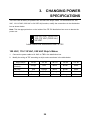
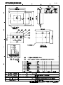
3. CHANGING POWER
SPECIFICATIONS
This unit is set at factory to operate from 220-230 VAC ship's mains. For connection to a 100
VAC, 110-115 VAC, 200 VAC or 24 VDC ship's mains, modify the connections in the distribution
box as shown below.
Note: Tick the appropriate box on the inside of the FE-702 distribution box cover to denote the
power use.
200-230 VAC (50/60 Hz)
100-115 VAC (50/60 Hz)
24 VDC
Label inside the distribution box FE-702
100 VAC, 110-115 VAC, 200 VAC Ship's Mains
1.
Connect the power cable to #1 & #3 on TB5 in the distribution box.
2.
Modify the wiring at TB7 according to ship's mains as shown in the table below.
Ship's mains
TB7 #1
TB7 #2
TB7 #3
TB7 #4
TB7 #5
Orange
Red
Black
Brown
White
Red
Orange
Black
Brown
White
110-115 VAC
Black
Red
Orange
Brown
White
100VAC
Brown
Red
Black
Orange
White
220-230 VAC
(Default)
200 VAC
20
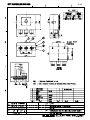
24 VDC Ship's Mains
1.
Remove the cover of the distribution box.
2.
Remove P3 connector from J4 on the CONE Board.
3.
Reattach P3 connector to J3 on the CONE Board.
4.
Connect the power cable to TB6.
J1
J3
J4
J2
TB5
TB6
For DC ship's mains
For AC ship's mains
Distribution box, inside view
21
CONE Board
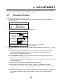
4. ADJUSTMENTS
This section provides the procedures for initial set up of the equipment. The type of transducer
used should be properly set before operating the equipment.
4.1
Transducer Setting
Select the type of transducer used as follows.
1. Press the POWER Switch while pressing any key. Release the key when the following
display appears.
+:
-:
▲:
▼:
EXTENSION MODE
TRANSDUCER SETTING
TEST
CLEAR MEMORY
DEMONSTRATION
2. Press the [+] key to select TRANSDUCER SETTING.
TRANSDUCER SETTING
CHANGEOVER : AUTO MANUAL
[FORE] XDR : N/A 50kHz 200kHz
KEEL DIST. : 0.0 m(0.0-10.0)
[AFT] XDR : N/A 50 kHz 200kHz
KEEL DIST. : 0.0 m(0.0-10.0)
DEPTH(BELOW) TRANSDUCER KEEL
DISP MODE : DUAL SINGLE
DISP ORDER*: AFT/FORE FORE/AFT
OUTPUT* : FORE AFT
MEMORIZE* : DUAL FORE AFT
* Does not appear when DISP MODE
: To select item
is set to SINGLE.
- +: To set option
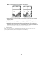
3. Set the transducer(s) as shown below. Use [▲] or [▼] to select an item and [+] or [-] to set
option.
a) CHANGEOVER sets how transducer(s) is connected to the FE-700. Select MANUAL for
single transducer or transducers connected via Switch Box EX-8. Select AUTO for
connection via Distribution Box MB-1200.
b) One transducer installed: Set FORE XDR to 50 kHz or 200 kHz, depending on actual
installation. Leave AFT XDR set to “N/A."
Two transducers installed: Set FORE XDR and AFT XDR to 50 kHz or 200 kHz, depending
on actual installation.
c) KEEL DIST sets the distance from transducer to keel of the ship.
d) DEPTH (BELOW) selects the method of depth indication. TRANSDUCER for depth
indication below the transducer (except DBS mode), or KEEL for depth indication below the
keel.
e) DISP MODE sets the function of the MODE switch in case of dual frequencies. Select DUAL
to show the dual frequency display (fore and aft), or SINGLE to show single frequency
display.
22
Note: If CHANGEOVER is set for MANUAL, select SINGLE.
0
0
20
20
40
40
60
60
49.6m
BELOW SURFACE
49.6
BELOW SURFACE
80
SINGLE: Single frequency
f)
49.6
m
80
DUAL: Dual frequency
DISP ORDER sets where to locate the fore and aft displays (right or left side) in the dual
frequency display.
g) OUTPUT sets what data to output to external equipment (in IEC/NMEA data format) in case
of dual frequencies. Select FORE to output FORE data, or AFT to output AFT data.
h) MEMORIZE sets the source (transducer) for data recording (depth, etc.) in case of dual
frequencies. Select DUAL, FORE or AFT as appropriate. DUAL records both FORE and AFT
data for 12 hours. FORE or AFT records respective data for 24 hours.
4. Reset the power.
Note: The default settings in the TRANSDUCER SETTING window are N/A. At the first
power-up after installation, the window appears to set transducer(s).
23
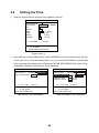
4.2
1.
Setting the Time
Open the system menu 2 referring to the operator’s manual.
SYSTEM MENU 2
MENU SELECT 1 2 3
TIME ADJUST
INTERNAL EXTERNAL
DAY
1
MONTH
JAN
YEAR
2009
( 2100)
HOUR
0
(0 23)
MINUTE
1
(0 59)
SECOND
42
(0 59)
01 JAN 2009
00:01:06
TS : To select item
- +: To set option
Select other mode to exit.
System menu 2
2.
Press [▼] key to select TIME ADJUST. Select INTERNAL to use the internal clock. Set day,
month, year, hour, minute and second with [+] or [-] key. Select EXTERNAL to use time data
from equipment that outputs time in ZDA format. At TIME DIFFERENCE field, select AUTO
or MANUAL. MANUAL requires entry of time difference.
SYSTEM MENU 2
MENU SELECT
1 2 3
TIME ADJUST
INTERNAL EXTERNAL
TIME DIFFERENCE AUTO MANUAL
01 JAN 2009
SYSTEM MENU 2
MENU SELECT
1 2 3
TIME ADJUST
INTERNAL EXTERNAL
TIME DIFFERENCE AUTO MANUAL
TIME DIFF HOUR
0 (0~13)
TIME DIFF MIN
0 (0~59)
TIME DIFF SIGN
- (0~59)
00:02:10
01 JAN 2009
00:02:10
TS :
TS :
To select item
- +: To set option.
Select other mode to exit.
To select item
- +: To set option.
Select other mode to exit.
TIME ADJUST set to EXTERNAL
TIME DIFFERENCE set to MANUAL
24
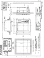
&1%7/'06
+056#..#6+10/#6'4+#.5
#%%'5514+'5
70+6
176.+0'
+/'
1/'
/,#52(%
/,#52(
(/%(25
%2
%2
(2
(2
(2
('('*-
36;
䋨⇛࿑䈱ኸᴺ䈲䇮ෳ⠨୯䈪䈜䇯㩷㩷㪛㪠㪤㪜㪥㪪㪠㪦㪥㪪㩷㪠㪥㩷㪛㪩㪘㪮㪠㪥㪞㩷㪝㪦㪩㩷㪩㪜㪝㪜㪩㪜㪥㪚㪜㩷㪦㪥㪣㪰㪅䋩
(+:
㪫㪮㪦㩷㪫㪰㪧㪜㪪㩷㪘㪥㪛㩷㪚㪦㪛㪜㪪㩷㪤㪘㪰㩷㪙㪜㩷㪣㪠㪪㪫㪜㪛㩷㪝㪦㪩㩷㪘㪥㩷㪠㪫㪜㪤㪅㩷㩷㪫㪟㪜㩷㪣㪦㪮㪜㪩㩷㪧㪩㪦㪛㪬㪚㪫㩷㪤㪘㪰㩷㪙㪜㩷㪪㪟㪠㪧㪧㪜㪛㩷㪠㪥㩷㪧㪣㪘㪚㪜㩷㪦㪝㩷㪫㪟㪜㩷㪬㪧㪧㪜㪩㩷
㪧㪩㪦㪛㪬㪚㪫㪅㩷㪨㪬㪘㪣㪠㪫㪰㩷㪠㪪㩷㪫㪟㪜㩷㪪㪘㪤㪜㪅
ဳᑼ㪆䍘䍎䍢䍼⇟ภ䈏䋲Ბ䈱႐ว䇮ਅᲑ䉋䉍Ბ䈮ઍ䉒䉎ㆊᷰᦼຠ䈪䈅䉍䇮䈬䈤䉌䈎䈏䈦䈩䈇䉁䈜䇯䇭䈭䈍䇮ຠ⾰䈲ᄌ䉒䉍䉁䈞䉖䇯
A-1
(+: &'5%4+26+10%1&'ͳ
䍘㪄䍢䍼⇟ภᧃየ䈱㪲㪁㪁㪴䈲䇮ㆬᛯຠ䈱ઍ䍘䍎䍢䍼䉕䈚䉁䈜䇯
㪚㪦㪛㪜㩷㪥㪬㪤㪙㪜㪩㩷㪜㪥㪛㪠㪥㪞㩷㪮㪠㪫㪟㩷㩹㪁㪁㩹㩷㪠㪥㪛㪠㪚㪘㪫㪜㪪㩷㪫㪟㪜㩷㪚㪦㪛㪜㩷㪥㪬㪤㪙㪜㪩㩷㪦㪝㩷㪩㪜㪧㪩㪜㪪㪜㪥㪫㪘㪫㪠㪭㪜㩷㪤㪘㪫㪜㪩㪠㪘㪣㪅
+056#..#6+10/#07#.
ⵝⷐ㗔ᦠ
12'4#6145/#07#.
ขᛒ⺑ᦠ
࿑ᦠ
%#$.'#55;
㩃㨺㩖㩨㩣⚵ຠ/,
%#$.'#55;
㩃㨺㩖㩨㩣⚵ຠ/,
%#$.'#55;
㩃㨺㩖㩨㩣⚵ຠ
+056#..#6+10/#6'4+#.5
Ꮏ᧚ᢱ
Ꮏ᧚ᢱ
#%%'5514+'5
ઃዻຠ
*#4&%18'4
㩔㨺㩎㩨㩀㩔㩨㨺
ઃዻຠ
&+52.#;70+6
ᜰ␜ེ
࡙࠾࠶࠻
0#/'
('('*-
㧼㧭㧯㧷㧵㧺㧳ޓ㧸㧵㧿㨀
(+.6'4
㩖㨲㩣㩊
'/+
ฬޓޓ⒓
0#/'
⇛ޓޓ࿑
176.+0'
%1&'01
'5&54
ဳฬ㧛ⷙᩰ
&'5%4+26+105
%2
6;2'
ᢙ㊂
36;
↪ㅜ㧛⠨
4'/#4-5
(+: 㧲㨁㧾㨁㧺㧻ޓ㧱㧸㧱㧯㨀㧾㧵㧯ޓ㧯㧻ޓ㧚㧘㧸㨀㧰
㧔⇛࿑ߩኸᴺߪޔෳ⠨୯ߢߔ&ޓޕ+/'05+105+0&4#9+0)(144'('4'0%'10.;㧕
(+:
6916;2'5#0&%1&'5/#;$'.+56'&(14#0+6'/6*'.19'4241&7%6/#;$'5*+22'&+02.#%'1(6*'722'4241&7%6
37#.+6;+56*'5#/'
ဳᑼ㩄㨺㩎㩨⇟ภ߇㧞Ბߩ႐วޔਅᲑࠃࠅᲑߦઍࠊࠆㆊᷰᦼຠߢࠅޔ߅ߥޓޕߔ߹ߡߞ߇߆ࠄߜߤޔຠ⾰ߪᄌࠊࠅ߹ߖࠎޕ
⇟ภ
01
+056#..#6+10/#6'4+#.5
Ꮏ᧚ᢱ
%1&'01
A-2
5'.(6#22+0)5%4'9
㩎㩡㩇㩊㨹㩕㩩㩧㩒㩆㩨ޓ㩆㨷
&7//;(+./
-
㩖㩨㩡㨼㩧㩎㩨㩖㨲㩣㩛
-
ฬޓޓ⒓
0#/'
%1&'
01
:575
%1&'
01
41*5
㧲㨁㧾㨁㧺㧻ޓ㧱㧸㧱㧯㨀㧾㧵㧯ޓ㧯㧻ޓ㧚㧘㧸㨀㧰
㧔⇛࿑ߩኸᴺߪޔෳ⠨୯ߢߔ&ޓޕ+/'05+105+0&4#9+0)(144'('4'0%'10.;㧕
():
ဳᑼ㩄㨺㩎㩨⇟ภ߇㧞Ბߩ႐วޔਅᲑࠃࠅᲑߦઍࠊࠆㆊᷰᦼຠߢࠅޔ߅ߥޓޕߔ߹ߡߞ߇߆ࠄߜߤޔຠ⾰ߪᄌࠊࠅ߹ߖ
ࠎޕ
6916;2'5#0&%1&'5/#;$'.+56'&(14#0+6'/6*'.19'4241&7%6/#;$'5*+22'&+02.#%'1(6*'722'4
241&7%637#.+6;+56*'5#/'
⇟ภ
01
⌕┵ሶޓޓޓޓޓޓ
ޓޓ
%4+/210.7)
%4+/210.7)
⌕┵ሶ
5'.(6#22+0)5%4'9
㩎㩡㩇㩊㨹㩕㩩㩧㩒㩆㩨ޓ㩆㨷
ฬޓޓ⒓
0#/'
⇛ޓޓ࿑
176.+0'
ဳฬ㧛ⷙᩰ
&'5%4+26+105
%2
%1&'
01
(85㨻㨿
(85
%1&'
01
(8
.(
%1&'
01
:575
6;2'
%1&'01
ᢙ㊂
36;
↪ㅜ㧛⠨
4'/#4-5
(+: A-4
㧲㨁㧾㨁㧺㧻ޓ㧱㧸㧱㧯㨀㧾㧵㧯ޓ㧯㧻ޓ㧚㧘㧸㨀㧰
㧔⇛࿑ߩኸᴺߪޔෳ⠨୯ߢߔ&ޓޕ+/'05+105+0&4#9+0)(144'('4'0%'10.;㧕
(+:
ဳᑼ㩄㨺㩎㩨⇟ภ߇㧞Ბߩ႐วޔਅᲑࠃࠅᲑߦઍࠊࠆㆊᷰᦼຠߢࠅޔ߅ߥޓޕߔ߹ߡߞ߇߆ࠄߜߤޔຠ⾰ߪᄌࠊࠅ߹ߖ
ࠎޕ
6916;2'5#0&%1&'5/#;$'.+56'&(14#0+6'/6*'.19'4241&7%6/#;$'5*+22'&+02.#%'1(6*'722'4
241&7%637#.+6;+56*'5#/'
⇟ภ
01
+056#..#6+10/#6'4+#.5
↪ㅜ㧛⠨
4'/#4-5
#%%'5514+'5
ᢙ㊂
36;
(): Ꮏ᧚ᢱ
ဳฬ㧛ⷙᩰ
&'5%4+26+105
(2
6;2'
ઃዻຠ
⇛ޓޓ࿑
176.+0'
%1&'01
A-3
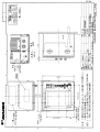
70+6
+056#..#6+10/#6'4+#.5
#%%'5514+'5
176.+0'
/,#52(
/,#52(%
/,#52(%
%2
%2
(2
(2
(2
(2
('('*-
36;
䋨⇛࿑䈱ኸᴺ䈲䇮ෳ⠨୯䈪䈜䇯㩷㩷㪛㪠㪤㪜㪥㪪㪠㪦㪥㪪㩷㪠㪥㩷㪛㪩㪘㪮㪠㪥㪞㩷㪝㪦㪩㩷㪩㪜㪝㪜㪩㪜㪥㪚㪜㩷㪦㪥㪣㪰㪅䋩
(+:
㪫㪮㪦㩷㪫㪰㪧㪜㪪㩷㪘㪥㪛㩷㪚㪦㪛㪜㪪㩷㪤㪘㪰㩷㪙㪜㩷㪣㪠㪪㪫㪜㪛㩷㪝㪦㪩㩷㪘㪥㩷㪠㪫㪜㪤㪅㩷㩷㪫㪟㪜㩷㪣㪦㪮㪜㪩㩷㪧㪩㪦㪛㪬㪚㪫㩷㪤㪘㪰㩷㪙㪜㩷㪪㪟㪠㪧㪧㪜㪛㩷㪠㪥㩷㪧㪣㪘㪚㪜㩷㪦㪝㩷㪫㪟㪜㩷㪬㪧㪧㪜㪩㩷
㪧㪩㪦㪛㪬㪚㪫㪅㩷㪨㪬㪘㪣㪠㪫㪰㩷㪠㪪㩷㪫㪟㪜㩷㪪㪘㪤㪜㪅
ဳᑼ㪆䍘䍎䍢䍼⇟ภ䈏䋲Ბ䈱႐ว䇮ਅᲑ䉋䉍Ბ䈮ઍ䉒䉎ㆊᷰᦼຠ䈪䈅䉍䇮䈬䈤䉌䈎䈏䈦䈩䈇䉁䈜䇯䇭䈭䈍䇮ຠ⾰䈲ᄌ䉒䉍䉁䈞䉖䇯
A-5
(+: &'5%4+26+10%1&'ͳ
䍘㪄䍢䍼⇟ภᧃየ䈱㪲㪁㪁㪴䈲䇮ㆬᛯຠ䈱ઍ䍘䍎䍢䍼䉕䈚䉁䈜䇯
㪚㪦㪛㪜㩷㪥㪬㪤㪙㪜㪩㩷㪜㪥㪛㪠㪥㪞㩷㪮㪠㪫㪟㩷㩹㪁㪁㩹㩷㪠㪥㪛㪠㪚㪘㪫㪜㪪㩷㪫㪟㪜㩷㪚㪦㪛㪜㩷㪥㪬㪤㪙㪜㪩㩷㪦㪝㩷㪩㪜㪧㪩㪜㪪㪜㪥㪫㪘㪫㪠㪭㪜㩷㪤㪘㪫㪜㪩㪠㪘㪣㪅
%#$.'#55;
㩃㨺㩖㩨㩣⚵ຠ/,
%#$.'#55;
㩃㨺㩖㩨㩣⚵ຠ/,
+056#..#6+10/#6'4+#.5
Ꮏ᧚ᢱ
Ꮏ᧚ᢱ
#%%'5514+'5
ઃዻຠ
(.75*/1706+0)2#0'.
㩖㩡㨹㩆㨷㩙㨽㩧㩎5
(.75*/1706+0)2#0'.
㩖㩡㨹㩆㨷㩙㨽㩧㩎(
ઃዻຠ
&+)+6#.&'26*+0&+%#614
ᷓᐲ␜ེ
࡙࠾࠶࠻
0#/'
('*-
㧼㧭㧯㧷㧵㧺㧳ޓ㧸㧵㧿㨀
%4+/210.7)
⌕┵ሶ
ฬޓޓ⒓
0#/'
⇛ޓޓ࿑
176.+0'
%1&'
01
(8
.(
ဳฬ㧛ⷙᩰ
&'5%4+26+105
ᢙ㊂
36;
%2
6;2'
↪ㅜ㧛⠨
4'/#4-5
#&: 㧲㨁㧾㨁㧺㧻ޓ㧱㧸㧱㧯㨀㧾㧵㧯ޓ㧯㧻ޓ㧚㧘㧸㨀㧰
㧔⇛࿑ߩኸᴺߪޔෳ⠨୯ߢߔ&ޓޕ+/'05+105+0&4#9+0)(144'('4'0%'10.;㧕
#&:
ဳᑼ㩄㨺㩎㩨⇟ภ߇㧞Ბߩ႐วޔਅᲑࠃࠅᲑߦઍࠊࠆㆊᷰᦼຠߢࠅޔ߅ߥޓޕߔ߹ߡߞ߇߆ࠄߜߤޔຠ⾰ߪᄌࠊࠅ߹ߖ
ࠎޕ
6916;2'5#0&%1&'5/#;$'.+56'&(14#0+6'/6*'.19'4241&7%6/#;$'5*+22'&+02.#%'1(6*'722'4
241&7%637#.+6;+56*'5#/'
⇟ภ
01
+056#..#6+10/#6'4+#.5
Ꮏ᧚ᢱ
%1&'01
A-6
*':$1.6
5.166'&
*'#&
ⷺ㩇㩢㩦㩢ޓ㩘㩨㩣㩎
524+0)9#5*'4
㩔㩨㩒ᐳ㊄
%15/'6+%2#0'.
ൻ♆㩔㩩㩒㩣
ฬޓޓ⒓
0#/'
%1&'
01
/:575
%1&'
01
/575
%1&'
01
㧲㨁㧾㨁㧺㧻ޓ㧱㧸㧱㧯㨀㧾㧵㧯ޓ㧯㧻ޓ㧚㧘㧸㨀㧰
㧔⇛࿑ߩኸᴺߪޔෳ⠨୯ߢߔ&ޓޕ+/'05+105+0&4#9+0)(144'('4'0%'10.;㧕
#&:
ဳᑼ㩄㨺㩎㩨⇟ภ߇㧞Ბߩ႐วޔਅᲑࠃࠅᲑߦઍࠊࠆㆊᷰᦼຠߢࠅޔ߅ߥޓޕߔ߹ߡߞ߇߆ࠄߜߤޔຠ⾰ߪᄌࠊࠅ߹ߖ
ࠎޕ
6916;2'5#0&%1&'5/#;$'.+56'&(14#0+6'/6*'.19'4241&7%6/#;$'5*+22'&+02.#%'1(6*'722'4
241&7%637#.+6;+56*'5#/'
⇟ภ
01
*':$1.6
5.166'&*'#&
ⷺ㩇㩢㩦㩢ޓ㩘㩨㩣㩎
524+0)9#5*'4
㩔㩨㩒ᐳ㊄
9+0)5%4'9
Ⲕ㩘㩨㩣㩎
9+0)076
Ⲕ㩏㨹㩎
(+:+0)2.#6'(14
(.75*/1706
㩖㩡㨹㩆㨷㩙㨽㩧㩎
ฬޓޓ⒓
0#/'
⇛ޓޓ࿑
176.+0'
ဳฬ㧛ⷙᩰ
&'5%4+26+105
(2
%1&'01
/:575
%1&'01
/575
%1&'01
/:;$5%
%1&'01
/;$5%
%1&'01
41*5
6;2'
%1&'01
ᢙ㊂
36;
↪ㅜ㧛⠨
4'/#4-5
#&: A-8
㧲㨁㧾㨁㧺㧻ޓ㧱㧸㧱㧯㨀㧾㧵㧯ޓ㧯㧻ޓ㧚㧘㧸㨀㧰
㧔⇛࿑ߩኸᴺߪޔෳ⠨୯ߢߔ&ޓޕ+/'05+105+0&4#9+0)(144'('4'0%'10.;㧕
#&:
6916;2'5#0&%1&'5/#;$'.+56'&(14#0+6'/6*'.19'4241&7%6/#;$'5*+22'&+02.#%'1(6*'722'4241&7%6
37#.+6;+56*'5#/'
ဳᑼ㩄㨺㩎㩨⇟ภ߇㧞Ბߩ႐วޔਅᲑࠃࠅᲑߦઍࠊࠆㆊᷰᦼຠߢࠅޔ߅ߥޓޕߔ߹ߡߞ߇߆ࠄߜߤޔຠ⾰ߪᄌࠊࠅ߹ߖࠎޕ
⇟ภ
01
#%%'5514+'5
↪ㅜ㧛⠨
4'/#4-5
#%%'5514+'5
ᢙ㊂
36;
#&: ઃዻຠ
ဳฬ㧛ⷙᩰ
&'5%4+26+105
(2
6;2'
ઃዻຠ
⇛ޓޓ࿑
176.+0'
%1&'01
A-7
5'.(6#22+0)5%4'9
㩎㩡㩇㩊㨹㩕㩩㩧㩒㩆㩨㩆㨷
⇛ޓޓ࿑
176.+0'
%1&'01
:575
ဳฬ㧛ⷙᩰ
&'5%4+26+105
ᢙ㊂
36;
↪ㅜ㧛⠨
4'/#4-5
㧲㨁㧾㨁㧺㧻ޓ㧱㧸㧱㧯㨀㧾㧵㧯ޓ㧯㧻ޓ㧚㧘㧸㨀㧰
㧔⇛࿑ߩኸᴺߪޔෳ⠨୯ߢߔ&ޓޕ+/'05+105+0&4#9+0)(144'('4'0%'10.;㧕
#&:
6916;2'5#0&%1&'5/#;$'.+56'&(14#0+6'/6*'.19'4241&7%6/#;$'5*+22'&+02.#%'1(6*'722'4241&7%6
37#.+6;+56*'5#/'
ဳᑼ㩄㨺㩎㩨⇟ภ߇㧞Ბߩ႐วޔਅᲑࠃࠅᲑߦઍࠊࠆㆊᷰᦼຠߢࠅޔ߅ߥޓޕߔ߹ߡߞ߇߆ࠄߜߤޔຠ⾰ߪᄌࠊࠅ߹ߖࠎޕ
ฬޓޓ⒓
0#/'
%4+/210.7)
⌕┵ሶ
%4+/210.7)
⌕┵ሶ
5'.(6#22+0)5%4'9
㩎㩡㩇㩊㨹㩕㩩㩧㩒㩆㩨㩆㨷
ฬޓޓ⒓
0#/'
⇛ޓޓ࿑
176.+0'
ဳฬ㧛ⷙᩰ
&'5%4+26+105
%2
%1&'
01
(8/
(8/
%1&'
01
(8
.(
%1&'
01
:575
6;2'
%1&'01
ᢙ㊂
36;
↪ㅜ㧛⠨
4'/#4-5
#&: A-10
㧲㨁㧾㨁㧺㧻ޓ㧱㧸㧱㧯㨀㧾㧵㧯ޓ㧯㧻ޓ㧚㧘㧸㨀㧰
㧔⇛࿑ߩኸᴺߪޔෳ⠨୯ߢߔ&ޓޕ+/'05+105+0&4#9+0)(144'('4'0%'10.;㧕
#&:
ဳᑼ㩄㨺㩎㩨⇟ภ߇㧞Ბߩ႐วޔਅᲑࠃࠅᲑߦઍࠊࠆㆊᷰᦼຠߢࠅޔ߅ߥޓޕߔ߹ߡߞ߇߆ࠄߜߤޔຠ⾰ߪᄌࠊࠅ߹ߖ
ࠎޕ
6916;2'5#0&%1&'5/#;$'.+56'&(14#0+6'/6*'.19'4241&7%6/#;$'5*+22'&+02.#%'1(6*'722'4
241&7%637#.+6;+56*'5#/'
⇟ภ
01
+056#..#6+10/#6'4+#.5
⇟ภ
01
#%%'5514+'5
#&: Ꮏ᧚ᢱ
(2
6;2'
ઃዻຠ
%1&'01
A-9
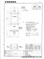
).#5567$'
(75'
㩕㨷㨺㩇㩨
).#5567$'
(75'
㩕㨷㨺㩇㩨
).#5567$'
(75'
㩕㨷㨺㩇㩨
()/$8#
2$(
()/$8#
2$(
()/$8
#2$(
2'4
8'5
5'652'4
8'55'.
$1:012
ဳᑼ㩄㨺㩎㩨⇟ภ߇㧞Ბߩ႐วޔਅᲑࠃࠅᲑߦઍࠊࠆㆊᷰᦼຠߢࠅޔ߅ߥޓޕߔ߹ߡߞ߇߆ࠄߜߤޔຠ
⾰ߪᄌࠊࠅ߹ߖࠎޕ
6916;2'5#0&%1&'5/#;$'.+56'&(14#0+6'/6*'.19'4241&7%6/#;$'5*+22'&+02.#%'1(
6*'722'4241&7%637#.+6;+56*'5#/'
㧔⇛࿑ߩኸᴺߪޔෳ⠨୯ߢߔ&ޓޕ+/'05+105+0&4#9+0)(ޓ144'('4'0%'10.;㧕
&9)01
2'4
5'6
A-11
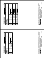
(+: 4'/#4-5%1&'01
(+:
37#06+6;
914-+0)
52#4'
52
75'
6;2'
&9)01
14
6;2'01
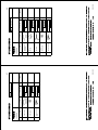
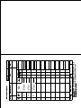
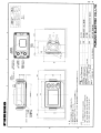
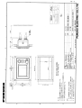
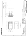
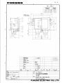
(74701'.'%64+%%1.6&
176.+0'
52#4'2#465.+56(14
0#/'1(
2#46
/(450#/'
+6'/
01
5*+201
%1&'01
D-3a
D-13
Y. Hatai
D-14
Y. Hatai
D-15
Y. Hatai
D-16
Takahashi.T
D-17
Y. Hatai
D-18
Y. Hatai
D-19
Apr.28'06
T.MAtsuguchi
D-20
Apr.28'06
T.Matsuguchi
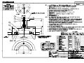
接続箱
J.B
*1
DPYCYS-2.5
TB1
TB2
1a 2a 3a
1T 2T 3T
D
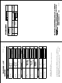
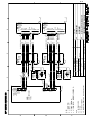
NOTE
*1. SHIPYARD SUPPLY.
*2. OPTION.
*3. FITTED AT FACTORY.
*4. USE A DISTRIBUTION BOX OR A MATCHING BOX WHEN TWO TRANSDUCERS ARE INSTALLED.
*5. TRANSMIT FREQUENCY IS SET TO 200 kHz AT FACTORY.
CHANGE THE SETTING FROM MENU FOR 50 kHz USE.
*6. REFER TO FE-720 INTERCONNECTION DIAGRAM FOR DETAIL.
1 2 3
FM-C6FPS003
2m,φ7.5 *2
アカ RED
クロ BLK
YEL
キ
ミドリ GRN
1 2 3
5 2 1
4 3
*1
IV-2sq.
DPYCYS-2.5 *1
1 2 3
*1
注記
*1)造船所手配。
*2)オプション。
*3)工場にて取付済み。
*4)2台の送受波器を装備するときは、切換器または接続箱を使用すること。
*5)本体の周波数は工場出荷時に200kHzに設定。
50kHzのときは必ずメニュー設定を変更のこと。
*6)接続の詳細はFE-720相互結線図を参照のこと。
*2
1 2 3 4 5
分配箱
DISTRIBUTION BOX
MB-1200 *2
1 2 3
*1
IV-2sq.
接続箱
J.B *1
1 2 3
1 2 3
1 2 3
接続箱
J.B *1
DPYCYS-2.5 *1
整合箱
MATCHING BOX
MB-502(50B-6B)
MB-504(200B-8B)
1a 2a 3a
1T 2T 3T
整合箱
MATCHING BOX
1a 2a 3a
MB-502(50B-6B) 1T 2T 3T
MB-504(200B-8B)
1a 2a 3a
1T 2T 3T
TB1
*1
IV-2sq.
C
送受波器切替器
TRANSDUCER
1 2 3 4 5
SWITCH BOX
EX-8
1a 2a 3a
1T 2T 3T
TB2
TB6
1 (+) DC電源使用時要改造
2
MODIFICATION IS REQUIRED
3 (-) TO USE DC SOURCE.
TB1
*1
DPYCYS-1.5
FM-C6FPS002,10m,φ7.5
アカ RED
クロ BLK
5
4
3
2
1
TB2
24 VDC
TB5
1 U
2
3 V
TB4
XDR-M
XDR-P
SHIELD
XDR-M
XDR-P
TB1
100/110-115/
200/220-230 VAC,
1φ,50/60Hz
*1
DPYCYS-1.5
*1
IV-2sq.
TB2
P
AFT
XDR
B
1
2
3
4
5
6
P
TB3
TD1-A
TD1-B
24V
0V
GND
TD1-A
TD1-B
24V
0V
GND
TB2
P
*1
TTYCYS-4
1
2
3
4
5
6
7
8
9
10
TB1
P
1
2
3
4
5
6
7
8
9
10
TB2
航法装置
NAV EQUIPMENT
IEC61162-1
1
2
3
4
5
6
7
8
9
10
XDR
J3
XDR+
NC
XDRXDRSEL0
SHIELD
XDRSEL.GND
*1
TTYCYS-4
TD1-A
TD1-B
RD1-A
RD1-B
DATA
J2
TD2
RD2
GND
TD1-A
TD1-B
RD1-A
RD1-B
DP-ON
RELAY
SHIELD
*3
MJ-A10SPF
MJ-A10SPF0002,10m,φ9
6
指示器
DISPLAY UNIT
FE-701
*3
FM-C6FP
P
7
8
9
10
1
2
3
POWER
J1
(+)
(-)
SHIELD
FM-C6FPS003
2m,φ7.5 *2
アカ RED
クロ BLK
YEL
キ
ミドリ GRN
P
*3
MJ-A10SPF
J1
RD2
TD2
GND
TD1-A
TD1-B
RD1-A
RD1-B
DP-ON
RELAY
SHIELD
*3
MJ-A3SPF
TB3
*1
TTYCYS-4
MJ-A3SPF0015-100C,10m,φ7
シロ WHT
クロ BLK
5
FORE
XDR
*1
TPYCYS-1.5
TB2
24V+ 1
0V 2
SHIELD 3
TB1
または OR
1
2
3
4
5
6
TB1
NORMAL CLOSE
NORMAL OPEN
RELAY COMMON
EIA232-TD
EIA232-RD
GND
TB1
深度表示器
DEPTH INDICATOR
*6 FE-720
*1
DPYCYS-1.5
400m MAX.
パソコンまたはプリンタ
PC (EIA-232C) OR PRINTER
PP-505-FE
分配箱
FE-702
DISTRIBUTION BOX
400m MAX.
ALARM RELAY
NORMAL CLOSE/OPEN
4
*1
DPYCYS-2.5
A
3
2
TB2
1
2RNCT-SB 2Cx1.4
15/30/50m,φ11.8
2RNCT-SB 2Cx1.4
15/30/50m,φ11.8
50B-6B
200B-8B
50B-6B
200B-8B
50B-6B
200B-8B
50B-6B
200B-8B
送受波器 *5
TRANSDUCER
送受波器 *5
TRANSDUCER
50B-6B
200B-8B
送受波器 *5
TRANSDUCER
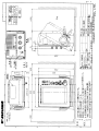
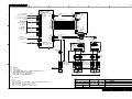
*4
DRAWN
11/Mar/09
CHECKED
12/Mar/09
APPROVED
SCALE
T.YAMASAKI
名称
T.TAKENO
MASS
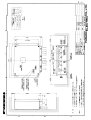
C2366-C01- N
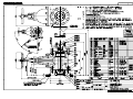
FE-700
音響測深機
相互結線図
25/Mar/09 R.Esumi
kg
DWG.No.
TITLE
NAME
NAVIGATIONAL ECHO SOUNDER
INTERCONNECTION DIAGRAM
S-1
C
B
A
P
P
P
P
P
P
*1
IV-2sq.
TB3
TD1-A 1
TD1-B 2
+24V 3
0V 4
GND 5
TD1-A 6
TD1-B 7
+24V 8
0V 9
GND 10
分配箱
DISTRIBUTION BOX
FE-702
TB1
NORMAL CLOSE 1
NORMAL OPEN 2
RELAY COMMON 3
EIA232-TD 4
EIA232-RD 5
GND 6
TD1-A 7
TD1-B 8
RD1-A 9
RD1-B 10
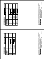
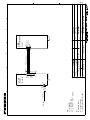
NOTE
*1. SHIPYARD SUPPLY.
*2. OPTION.
*3. FITTED AT FACTORY.
*4. REMOVE RESISTANCE 3kΩ FOR USING 200V SET.
注記
*1)造船所手配。
*2)オプション。
*3)工場にて取付済み。
*4)200V仕様では、固定抵抗3kΩを削除する。
1
U
V
L
U
V
L
*4
U
V
L
DWG.No.
SCALE
*1
IV-2sq.
7
8
1
2
3
4
5
6
端子台箱
*2
TERMINAL BOX
DS-802
*1
IV-2sq.
7
8
1
2
3
4
5
6
端子台箱
*2
TERMINAL BOX
DS-802
3
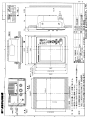
C2366-C02- K
MASS
kg
REF.No.
NAME
名称
TITLE
MJ-A6SPF0003-020C,2m
シロ WHT
クロ BLK
MJ-A7SPF0009-020C,2m
シロ WHT
アオ BLU
YEL
キ
ミドリ GRN
アカ RED
FUSE(1A)
クロ BLK
MJ-A6SPF0003-020C,2m
シロ WHT
クロ BLK
MJ-A7SPF0009-020C,2m
シロ WHT
アオ BLU
YEL
キ
ミドリ GRN
アカ RED
FUSE(1A)
クロ BLK
02-129-1004- 0
Apr.17'07 R.Esumi FE-700
T.TAKENO
T.YAMASAKI
*1
DPYC-1.5
*1
DPYC-1.5
Apr. 10 '07
CHECKED
Apr. 10 '07
APPROVED
DRAWN
3k
調光器 DIMMER
MF22L-1/2-200V
調光器
DIMMER *2
MF22L-1/2
-100V
*1
TTYCYS-4,30m MAX.
*1
TTYCYS-4
*4
3k
調光器 DIMMER
MF22L-1/2-200V
U
V
L
DPYC-1.5 *1
調光器
DIMMER *2
MF22L-1/2
-100V
24VDC
*1
TTYCYS-4,30m MAX.
2
1
2
3
4
5
6
1
2
3
4
5
6
7
1
2
3
4
5
6
1
2
3
4
5
6
7
TD-B
RD-A
RD-B
+24V
0V
SHIELD
J6
DIM-P
GND
GND
NC
NC
NC
深度表示器
DIGITAL DEPTH
J7 INDICATOR
FE-720
TD-A
TD-B
RD-A
RD-B
+24V
0V
SHIELD
J6
DIM-P
GND
GND
NC
NC
NC
深度表示器
DIGITAL DEPTH
J7 INDICATOR
FE-720
TD-A
*1
IV-1.25sq.
*1
IV-1.25sq.
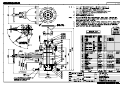
INTERCONNECTION DIAGRAM
DIGITAL DEPTH INDICATOR
相互結線図
FE-720
深度表示器
*3
MJ-A6SPF
*3
MJ-A7SPF
*3
MJ-A6SPF
*3
MJ-A7SPF
4
S-2
C
B
A
08S0157,3m
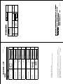
*3: GROUND THRU CONNECTOR CLAMP.
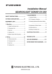
NOTE
*1: SHIPYARD SUPPLY.
*2: FITTED AT FACTORY.
注記
*1)造船所手配。
*2)工場にて取付済み。
*3)コネクタケースでアースをとる。
12-32 VDC
1
1
2
3
4
5
6
7
FM14-7P
*1
TPYCYS-1.5,MAX.10m
*2
FM14-2P
J2
アカ RED
1 +
クロ BLK
2 -
DWG.No.
SCALE
T.TAKENO
T.YAMASAKI
C2366-C03- E
MASS
Jan. 5'07 R.Esumi
Dec. 28 '06
CHECKED
Jan. 5 '07
APPROVED
DRAWN
08S0087,2m
*3
REF.No.
16-006-3022-0
FE-700
TB1
4 EIA232-TD
5 EIA232-RD
6 GND
NAME
名 称
TITLE
*1
IV-2sq.
FE-702
PP-505-FE
J1
RXD(H)
TXD(H)
0V
TXD(C)
RXD(C)
+12V
NC
分配箱
DISTRIBUTION BOX
3
プリンタ
PRINTER
2
PRINTER
INTERCONNECTION DIAGRAM
プリンタ
相互結線図
PP-505-FE
4
S-3