1
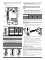
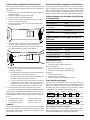
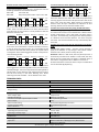
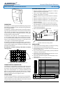
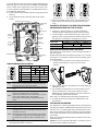
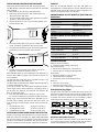
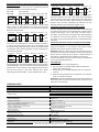
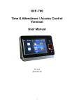
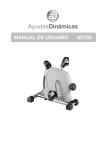
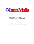
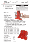
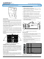
Acoustic Glass Break Detector Detectors Instruction and installation manual AD 700 MOUNTING INSTRUCTIONS DESCRIPTION AD 700 is an acoustic glass break detector giving an alarm when glass is smashed at intruder attempts through windows, doors and glazed walls. The detector is based on advanced microcontroller technology and programmed to take a lot of relevant acoustic factors into account: the Digital Room Compensation (DRC). This makes the detector able to distinguish between a true glass break and other irrelevant sounds. The detector is for indoor use. The coverage distance is 1–9 m. The coverage angle is 165º, which means that one detector can protect several windows in the same room. The detector can be mounted in the ceiling or on a wall with a free “line of sight” to the window being protected. AD 700 is certified according to EN 50131-2-7-1:2012, security grade 2. Detector should be installed on a ceiling or on a wall opposite to the glass to be protected Clear “line-of- sight” between the “microphone” of the detector and the glass is required Distance between the glass and the detector should be 19m Detector should be installed min. 50 cm from a corner Detector should be installed min. 1 m over the floor Detector should be installed min. 30 cm from the ceiling (at wall mounting) Detector should be installed on a flat surface, which is free from objects in a radius of 50 cm from the detector Detector should not be installed close to air vents or big sound reflecting obstacles Never mount the detector in the corners min. 0.5 m min. 0.5 m min. 1m Location for wall or ceiling mount INSTALLATION 1. Choose the best mounting position on the wall or ceiling. 2. Loosen the cover screw and remove the cover 3. Use the bottom part as a template and mark the place of the holes of with a pen 4. Use a 2.5 mm drill for the self-tapping screws provided. If necessary, use wall anchors 5. If necessary, cut out the marked “knockout hole” on the back of the base with a pair of tongs 6. Pull the wiring cable through the “knockout hole” in the bottom plate 7. Connect the wires to the screw terminals Coverage area in the acoustic room Zone 1-3 Pin 10 9 8 7 6 5 4 3 2 1 CONNECTION TO A 24-HOUR LOOP The detector is constructed for continuous supervision and is extra resistant to different acoustic disturbances. It will function well in most environments. However in rooms with very high rates of disturbances as in industrial workshops and gyms, it is recommended to test the detector for 3-4 weeks before deciding to use it continuously. In rare cases a combination of random sounds can trigger an alarm. SPECIAL TOOLS In most rooms (e.g. offices) no special tools are required during the installation. In rooms with complicated acoustics it is recommended to use the ADT 700 tester. ADT 700 can also be used for function test and annual service. © 2014 Alarmtech min. 0.3 m Marking Sp Sab Sab Sp NC C D/N AIS + - Function Spare terminal Tamper switch output Tamper switch output Spare terminal Relay output Normally Closed Relay output Common Day and Night control of LED Alarm Information System Plus 9 to 15 V DC Ground The terminals can be connected to the sabotage loop or the alarm loop (at your own choice). 1/4 AD700 manual 1419en 8. Use the cable strap provided to fix the wiring cable to the detector. 9. Fix the detector firmly to the base with the enclosed screws. Cable jacket „knock-out” Mounting hole PC interface LED Tamper switch Screw terminal 1 - 10 DIP switch 10. Set the desired range, i.e. the detector sensitivity setting by using the DIP switch no 4 and 5. 11. Check the window constructions and note what kind of glass is used and especially in the pane closest to the room. SUGGESTED SETTINGS OF THE DETECTOR DEPENDING ON WINDOW DESIGN AND TYPE OF GLASS: Float glass – Set the detector in accordance with the measured distance between the glass and the detector. Laminated glass – Set the detector to Zone 1 (4-9 m) regardless of the measured distance between the glass and the detector. The detector’s coverage area is 1-9 m. Range Glass Type 1–2 m 2–4 m 4–9 m float laminated P2 Zone 3 Zone 2 Zone 1 Zone 1 CHECK THE SETTINGS WITH ADT 700 TESTER If the detector is placed too far or too close from the glass, it will not respond. At DRC testing the LED of the detector will flash 1, 2 or 3 times to show it is in a certain Zone. If it does not flash a better place must be selected. 1. Put the cover on and make sure it hooks properly into the base of the detector. Fasten the cover screw properly. Microphone Mounting hole UNDERSTANDING THE DIP SWITCH 6 Audio test ON OFF 4-9 m DIP1 DIP2 DIP3 DIP4 DIP5 DIP6 2-4 m 1-2 m 5 Range setting ON ON OFF OFF 4 Range setting OFF ON OFF ON 3 D/N polarity NIGHT=Low NIGHT=High 2 LED mode AIS Monitor 1 Relay mode Latch Auto Relay mode ON means the relay will Latch and be open in alarm. Relay mode OFF means the relay will be Auto reset after 2 seconds in Alarm. LED mode ON means AIS (Alarm Information System) is on. D/N polarity mode ON means: DAY mode = high voltage or open, NIGHT mode = Low voltage. D/N polarity mode OFF means: DAY mode = low voltage or open, NIGHT mode = high voltage. Open input in both settings is interpreted as DAY mode 1-2 m 2-4 m 4-9 m Range setting ON OFF OFF Range setting OFF OFF ON Audio test ON means “hand-clap” test mode is on. Audio test OFF means “hand-clap” test mode is off. 4-9 m Zone 1 © 2014 Alarmtech 2-4 m Zone 2 1-2 m Zone 3 2. Apply power - LED will now indicate your range setting by blinking 1-3 times. 3. By a simple hand-clap test you can check that the microphone and electronic circuit works properly. Just Set DIP6 Audio test mode to ON state, clap your hands close to the detector and the LED will flash. Note: This is no indication of the sensitivity of the detector. 4. Use ADT700 to test and calibrate the detector for optimal position. TESTING AND CALIBRATING ADT 700 tester is a specially developed tool for calibrating and adjusting the detector AD700 AM for optimal function in the acoustic room – the DRC Digital Room Compensation procedure. When testing the detector settings you do not need to open it again as the tester will communicate with the detector acoustically. Never test the AD 700 with open lid. Make sure the lid is fastened properly. Caution: Do not use the ADT 700 tester in proximity to your ears as the tester produces loud noises. 2/4 AD700 manual 1419en DIGITAL ROOM COMPENSATION PROCEDURE PROTECTING SEVERAL WINDOWS BY ONE DETECTOR Prepare the acoustic detector for DRC by following steps. The DIP switches inside the detector should be set as follows before testing. If D/N and AIS line is not used, DIP2 LED shall be in Monitor mode (OFF state) D/N line (if used) should be in DAY mode AIS line (if used) should be in high state 1. Press the START button of the ADT 700 tester to put the power on. Green LED will light. 2. Hold the tester 0.7 to max 1.5 m from the detector and aim the speaker at it. AD 700 can protect several windows in one room if the windows are within the coverage area. Make independent DRC test for each window to be protected. Follow the procedure above for each window. The detector shall be set to the lowest Zone number that is the longest range from the detector. UNDERSTANDING THE LED WHEN THE DETECTOR IS IN OPERATION LED Detector status In Alarm; if Relay mode is in Latch Permanently on Flashes 1-3 times when powered ON Flashes when clapping your hands Flashes slowly for 2 seconds Indication of range setting Audio test on Low supply voltage UNDERSTANDING THE LED WHEN TESTING THE DETECTOR LED Flickers Flickers and blinks Flashes 1,5 s Blinks slowly 1 time each 2,5 s after calibration Blinks slowly 2 times each 2,5 s after calibration Blinks slowly 3 times each 2,5 s after calibration 3. Press the START button once more to initiate the DRC mode. The LED on the detector will start to flicker. 4. Go to the furthest distance (max. 9 m) of the glass to be protected and aim the speaker at the detector. Detector status In test mode In calibration mode Confirms received signal Set range setting to Zone 1 (4–9 m) Set range setting to Zone 2 (2–4 m) Set range setting to Zone 3 (1–2 m) TROUBLESHOOTING Detector does not respond Check the supply voltage and polarity 5. Press the DRC button to send a DRC signal out. Make this 2-10 times from different angles of the protection area for optimal capability. The LED will flash confirming it has received the signal. The LED will then start to blink and flicker. The DRC range calculated by the detector will be displayed as a number of pulses from 1 to 3. In case of too weak or too strong signals outside the compensation range (means that the detector is placed too close or too far from the object to be protected), the detector will then not show DRC range. 6. Press the STOP button from a distance of 0.7 to max 1.5 m from the detector to terminate the DRC procedure. If DRC range measured by the detector is different from actual DIP-switch settings, the LED will continue to blink 1-3 times showing the correct range number to be set in the detector. The LED blinks 1 time: set to Zone 1 (4–9 m) The LED blinks 2 times: set to Zone 2 (2–4 m) The LED blinks 3 times: set to Zone 3 (1–2 m) LED permanently on Switch off the detector for a short period Check if LED is in latching mode (DIP1=ON) TIMEOUT D/N control for DIP3 = ON, DAY = High or Open, NIGHT = Low Both the AD 700 detector and ADT 700 tester are equipped with a timeout feature. The AD 700 will stop the DRC mode and the ADT 700 will switch off power if no activity has happened within 3–4 minutes. AIS (Alarm Information System) © 2014 Alarmtech No alarm Check the alarm wiring Check the alarm loop wiring Check the power supply voltage and polarity D/N CONTROL (Day/Night) The D/N makes it possible to remote control the alarm indications of the detectors and remote reset during DAY->NIGHT transition. The D/N increases the security of the detector, as it enables the alarm indications to be concealed in NIGHT mode without any influence on the relay function. Control Unit +12 V A Detector 1 Detector 2 Detector 3 Detector 4 … etc 4 4 4 4 D/N D/N control for DIP3 = OFF, DAY = Low or Open, NIGHT = High Control Unit 0V A Detector 1 Detector 2 Detector 3 Detector 4 … etc 4 4 4 4 D/N AIS in conjunction with D/N is used to show which of detectors first was giving an alarm In NIGHT mode. AIS can also remotely enable detectors for testing by the ADT 700. 3/4 AD700 manual 1419en To test the function of the detectors with the ADT 700 Remote-control of day and night mode and indication of the detector giving first alarm Connect the detectors (max. 20 pcs) in accordance with the following schedule and set the DIP-switches. DIP2=ON LED mode: AIS DIP3=OFF D/N polarity: DAY mode = open line or low Control Unit +12 V A +12 V B Control Unit +12 V A +12 V B Detector 1 Detector 2 Detector 3 Detector 4 … etc 4 4 4 4 3 3 3 3 D/N AIS This is the initial configuration. The detectors are now in DAY mode. There is no LED indication of an alarm, but the alarm relay will open in case of alarm. It is not possible to test the detectors with ADT 700. Control Unit +12 V A +12 V B Detector 1 Detector 2 Detector 3 Detector 4 … etc 4 4 4 4 3 3 3 3 D/N AIS The detectors are now in NIGHT mode. There is no indication of an alarm. The information is stored in the Alarm memory. In case of alarm the relay will open. It is not possible to test the detectors with ADT 700. If the position of any DIP-switch is changed an alarm will be triggered. The alarm relay will follow the setting of DIP1. Control Unit +12 V A +12 V B Detector 1 Detector 2 Detector 3 Detector 4 … etc 4 4 4 4 3 3 3 3 D/N AIS Detector 1 Detector 2 Detector 3 Detector 4 … etc 4 4 4 4 3 3 3 3 D/N AIS Set the switches A and B in the position showed in figure above The detectors are now in DAY mode and prepared for receiving signals from the ADT 700 (See Function-test of the alarm relay using ADT 700). When testing is finished the switch B must be open. Otherwise the indication of first alarming detector will be blocked in NIGHT mode. Function test of the alarm relay using the ADT 700 tester Start the testing by pressing the start button at the ADT 700 at a distance of around 1 m from the detector. LED then starts to flash confirming it is set in test mode. The alarm relay is now open. End the test by pressing the ADT 700 stop button at a distance of 1m from the detector. The alarm relay will now close. The test will otherwise end up automatically after 4 minutes. Function test of the alarm relay by connecting to terminal 4 (D/N) Set DIP3=OFF (NIGHT mode) – connect +12V to terminal 4 (D/N) in the detector. If any change in the position of DIPswitches now is done, the alarm relay will open. Attention: If DIP1 is in OFF mode, the relay will be open for 2 seconds only and then close. If DIP1 is in ON mode, the relay will be open and close when the power is switched off or if the mode is changed from DAY to NIGHT on terminal 4. Another alternative to close the alarm relay is to switch DIP3 over to ON mode (D/N polarity). The detectors are now back in DAY mode. If some detectors have triggered an alarm during NIGHT mode, this will be indicated by LED light. The alarm relay follows the setting of DIP1. LED will flash on the detector that triggered the first alarm and will shine firmly on the other alarming ones. When switching from DAY to NIGHT – all the detectors are reset. TECHNICAL DATA Type (thickness) of protected glass Size of protected glass Max range Range setting Supply voltage Max. voltage ripple Voltage monitoring Current consumption quiescent/alarm state Alarm output Alarm contact rating Tamper contact rating Alarm indication Environmental class Operating temperature range Operating humidity range Housing material Dimensions: Security grade Approvals float (4 mm), laminated P2 (4 mm + 4 mm) min 40×40 cm 9 m radius/165° Zone 3 = 1–2 m Zone 2 = 2–4 m Zone 1 = 4–9 m 12 V DC (9 - 15 V DC) 2 Vpp at 12 V alarm at < 7 V ±0,5V 26 mA/24 mA @ 12 V DC relay 50 mA, 50 V DC/peak AC, Rs ≤ 30 Ω 50 mA/50 V DC/peak AC LED EN50130-5:2011, Class I +5°C to +40°C max. 93% RH plastic ABS 60x32x98 mm EN50131-2-7-1:2012, Grade 2 INCERT B-582-0017, F&P Registrated, SBSC 04-693 VdS Klasse B G104512 We reserve the right to changes without notice © 2014 Alarmtech 4/4 AD700 manual 1419en Acoustic Glass Break Detector Detectors Instruction and installation manual AD 700-AM MOUNTING INSTRUCTIONS DESCRIPTION AD 700-AM is an acoustic glass break detector giving an alarm when glass is smashed at intruder attempts through windows, doors and glazed walls. The detector is based on advanced microcontroller technology and programmed to take a lot of relevant acoustic factors into account: the Digital Room Compensation (DRC). This makes the detector able to distinguish between a true glass break and other irrelevant sounds. The detector is for indoor use. The coverage distance is 1–9 m. The coverage angle is 165º, which means that one detector can protect several windows in the same room. The detector can be mounted in the ceiling or on a wall with a free “line of sight” to the window being protected. AD 700-AM is equipped with an AM function, a separate relay, which gives an alarm at sabotage of microphone. The primary purpose of AM function is detection of damage or total blindness of microphone. AD 700-AM is certified according to EN 50131-2-7-1:2012, security grade 2. Coverage area in the acoustic room Zone 1-3 CONNECTION TO A 24-HOUR LOOP The detector is constructed for continuous supervision and is extra resistant to different acoustic disturbances. It will function well in most environments. However in rooms with very high rates of disturbances as in industrial workshops and gyms, it is recommended to test the detector for 3-4 weeks before deciding to use it continuously. In rare cases a combination of random sounds can trigger an alarm. Detector should be installed on a ceiling or on a wall opposite to the glass to be protected Clear “line-of- sight” between the “microphone” of the detector and the glass is required Distance between the glass and the detector should be 1-9 m Detector should be installed min. 50 cm from a corner Detector should be installed min. 1 m over the floor Detector should be installed min. 30 cm from the ceiling (at wall mounting) Detector should be installed on a flat surface, which is free from objects in a radius of 50 cm from the detector Detector should not be installed close to air vents or big sound reflecting obstacles Never mount the detector in the corners min. 0.5 m min. 0.5 m min. 1m Location for wall or ceiling mount INSTALLATION 1. Choose the best mounting position on the wall or ceiling. 2. Loosen the cover screw and remove the cover 3. Use the bottom part as a template and mark the place of the holes of with a pen 4. Use a 2.5 mm drill for the self-tapping screws provided. If necessary, use wall anchors 5. If necessary, cut out the marked “knockout hole” on the back of the base with a pair of tongs 6. Pull the wiring cable through the “knockout hole” in the bottom plate 7. Connect the wires to the screw terminals Pin Marking Function 10 Sp Spare terminal 9 Sab Tamper switch output 8 Sab Tamper switch output 7 Sp Spare terminal 6 NC Relay output Normally Closed 5 C Relay output Common 4 D/N Day and Night control of LED 3 AIS Alarm Information System 2 + Plus 9 to 15 V DC 1 Ground SPECIAL TOOLS In most rooms (e.g. offices) no special tools are required during the installation. In rooms with complicated acoustics it is recommended to use the ADT 700 tester. ADT 700 can also be used for function test and annual service. © 2014 Alarmtech min. 0.3 m 1 of 4 Pin Marking Function 11 C AM relay output Common 12 NC AM relay output Normally Closed The terminals can be connected to the sabotage loop or the alarm loop (at your own choice). AD700-AM manual 1419en In case of AM-alarm the relay will be opened. Depending on DIP6 setting you can select to have an audible or a silent AMalarm. In both cases a signal will be sent to the control unit. In case of AM-alarm the LED will be on (if DIP6=OFF) and separate AM-relay will be open. 8. Use the cable strap provided to fix the wiring cable to the detector. 9. Fix the detector firmly to the base with the enclosed screws. Cable jacket „knock-out” Mounting hole PC interface LED Screw terminal 11, 12 Tamper switch AM sounder Screw terminal 1 - 10 DIP switch Microphone Mounting hole UNDERSTANDING THE DIP SWITCH 6 DIP1 DIP2 DIP3 DIP4 DIP5 DIP6 AM mode 5 4 ON OFF 4-9 m 2-4 m 1-2 m ON OFF OFF Range setting ON ON OFF Range setting OFF ON 3 D/N polarity NIGHT=Low NIGHT=High 2 1 LED mode Relay mode AIS Latch Monitor Auto Relay mode ON means the relay will Latch and be open in alarm. Relay mode OFF means the relay will be Auto reset after 2 seconds in Alarm. LED mode ON means AIS (Alarm Information System) is on. D/N polarity mode ON means: DAY mode = high voltage or open, NIGHT mode = Low voltage. D/N polarity mode OFF means: DAY mode = low voltage or open, NIGHT mode = high voltage. Open input in both settings is interpreted as DAY mode 1-2 m 2-4 m 4-9 m Range setting ON OFF OFF Range setting OFF OFF ON AM mode ON means that the detector will give a silent AM-alarm in case of sabotage. Audio test mode “handclap” test is on. AM mode OFF means that the detector will send out an audible Buzzer signal in case of sabotage and will give AM-alarm. Audio test mode “handclap” test is off. 10. Set the desired range, i.e. the detector sensitivity setting by using the DIP switch no 4 and 5. © 2014 Alarmtech 4-9 m, Zone 1 2-4 m, Zone 2 1-2 m, Zone 3 11. Check the window constructions and note what kind of glass is used and especially in the pane closest to the room. SUGGESTED SETTINGS OF THE DETECTOR DEPENDING ON WINDOW DESIGN AND TYPE OF GLASS: Float glass – Set the detector in accordance with the measured distance between the glass and the detector. Laminated glass – Set the detector to Zone 1 (4-9 m) regardless of the measured distance between the glass and the detector. The detector’s coverage area is 1-9 m. Range Glass Type 1–2 m 2–4 m 4–9 m float Zone 3 Zone 2 Zone 1 laminated P2 Zone 1 CHECK THE SETTINGS WITH ADT 700 TESTER If the detector is placed too far or too close from the glass, it will not respond. At DRC testing the LED of the detector will flash 1, 2 or 3 times to show it is in a certain Zone. If it does not flash a better place must be selected. 1. Put the cover on and make sure it hooks properly into the base of the detector. Fasten the cover screw properly. 2. Apply power - LED will now indicate your range setting by blinking 1-3 times. 3. By a simple hand-clap test you can check that the microphone and electronic circuit works properly. Just Set DIP6 Audio test mode to ON state, clap your hands close to the detector and the LED will flash. Note: This is no indication of the sensitivity of the detector. 4. Use ADT700 to test and calibrate the detector for optimal position. TESTING AND CALIBRATING ADT 700 tester is a specially developed tool for calibrating and adjusting the detector AD700-AM for optimal function in the acoustic room – the DRC Digital Room Compensation procedure. When testing the detector settings you do not need to open it again as the tester will communicate with the detector acoustically. Never test the AD 700-AM with open lid. Make sure the lid is fastened properly. Caution: Do not use the ADT 700 tester in proximity to your ears as the tester produces loud noises. 2z4 AD700-AM manual 1419en DIGITAL ROOM COMPENSATION PROCEDURE TIMEOUT Prepare the acoustic detector for DRC by following steps: The DIP switches inside the detector should be set as follows before testing. DIP2 LED shall be in Monitor mode (OFF state). D/N line (if used) should be in DAY mode; AIS line (if used) should be in high state. 1. Press the START button of the ADT 700 tester to put the power on. Green LED will light. 2. Hold the tester 0.7 to max 1.5 m from the detector and aim the speaker at it. Both the AD 700-AM detector and ADT 700 tester are equipped with a timeout feature. The AD 700-AM will stop the DRC mode and the ADT 700 will switch off power if no activity has happened within 3–4 minutes. UNDERSTANDING THE LED WHEN THE DETECTOR IS IN OPERATION LED Detector status In Alarm; if Relay mode is in Latch Permanently on Flashes 1-3 times when powered ON Flashes when clapping your hands Flashes slowly for 2 seconds Indication of range setting Audio test on Low supply voltage UNDERSTANDING THE LED WHEN TESTING THE DETECTOR LED Flickers Flickers and blinks Flashes 1,5 s Blinks slowly 1 time each 2,5 s after calibration Blinks slowly 2 times each 2,5 s after calibration Blinks slowly 3 times each 2,5 s after calibration 3. Press the START button once more to initiate the DRC mode. The LED on the detector will start to flicker. 4. Go to the furthest distance (max. 9 m) of the glass to be protected and aim the speaker at the detector. Detector status In test mode In calibration mode Confirms received signal Set range setting to Zone 1 (4–9 m) Set range setting to Zone 2 (2–4 m) Set range setting to Zone 3 (1–2 m) TROUBLESHOOTING 5. The DRC range calculated by the detector will be displayed as a number of pulses from 1 to 3. Press the DRC button to send a DRC signal out. Make this 210 times from different angles of the protection area for optimal capability. The LED will flash confirming it has received the signal. The LED will then start to blink and flicker. The DRC range calculated by the detector will be displayed as a number of pulses from 1 to 3. In case of too weak or too strong signals outside the compensation range (means that the detector is placed too close or too far from the object to be protected), the detector will then not show DRC range. 6. Press the STOP button from a distance of 0,7 to max 1,5 m from the detector to terminate the DRC procedure. If DRC range measured by the detector is different from actual DIP-switch settings, the LED will continue to blink 1-3 times showing the correct range number to be set in the detector. The LED blinks 1 time: set to Zone 1 (4–9 m) The LED blinks 2 times: set to Zone 2 (2–4 m) The LED blinks 3 times: set to Zone 3 (1–2 m) PROTECTING SEVERAL WINDOWS BY ONE DETECTOR Detector can protect several windows in one room if the windows are within the coverage area. Make independent DRC test for each window to be protected. Follow the procedure above for each window. The detector shall be set to the lowest Zone number that is the longest range from the detector. © 2014 Alarmtech Detector does not respond Check the supply voltage and polarity LED permanently on Switch off the detector for a short period Check if LED is in latching mode (DIP1=ON) Audio signal AM-alarm if DIP6 is in OFF position Check if AM-alarm, sabotage Check if the cover was fastened properly No alarm Check the alarm wiring Check the alarm loop wiring Check the power supply voltage and polarity D/N CONTROL (Day/Night) The D/N makes it possible to remote control the alarm indications of the detectors and remote reset during DAY->NIGHT transition. The D/N increases the security of the detector, as it enables the alarm indications to be concealed in NIGHT mode without any influence on the relay function. Control Unit +12 V A Detector 1 Detector 2 Detector 3 Detector 4 … etc 4 4 4 4 D/N D/N control for DIP3 = OFF, DAY = Low or Open, NIGHT = High Control Unit 0V A Detector 1 Detector 2 Detector 3 Detector 4 … etc 4 4 4 4 D/N D/N control for DIP3 = ON, DAY = High or Open, NIGHT = Low AIS (Alarm Information System) AIS in conjunction with D/N is used to show which of detectors first was giving an alarm In NIGHT mode. AIS can also remotely enable detectors for testing by the ADT 700. 3z4 AD700-AM manual 1419en Remote-control of day and night mode and indication of the detector giving first alarm Connect the detectors (max. 20 pcs) in accordance with the following schedule and set the DIP-switches. DIP2=ON LED mode: AIS DIP3=OFF D/N polarity: DAY mode = open line or low Control Unit +12 V A +12 V B To test the function of the detectors with the ADT 700 Control Unit +12 V A +12 V B Detector 1 Detector 2 Detector 3 Detector 4 … etc 4 4 4 4 3 3 3 3 D/N AIS This is the initial configuration. The detectors are now in DAY mode. There is no LED indication of an alarm, but the alarm relay will open in case of alarm. It is not possible to test the detectors with ADT 700. Control Unit +12 V A +12 V B Detector 1 Detector 2 Detector 3 Detector 4 … etc 4 4 4 4 3 3 3 3 D/N AIS The detectors are now in NIGHT mode. There is no indication of an alarm. The information is stored in the Alarm memory. In case of alarm the relay will open. It is not possible to test the detectors with ADT 700. If the position of any DIP-switch is changed an alarm will be triggered. The alarm relay will follow the setting of DIP1. Control Unit +12 V A +12 V B Detector 1 Detector 2 Detector 3 Detector 4 … etc 4 4 4 4 3 3 3 3 D/N AIS The detectors are now back in DAY mode. If some detectors have triggered an alarm during NIGHT mode, this will be indicated by LED light. The alarm relay follows the setting of DIP1. LED will flash on the detector that triggered the first alarm and will shine firmly on the other alarming ones. When switching from DAY to NIGHT – all the detectors are reset. Detector 1 Detector 2 Detector 3 Detector 4 … etc 4 4 4 4 3 3 3 3 D/N AIS Set the switches A and B in the position showed in figure above The detectors are now in DAY mode and prepared for receiving signals from the ADT 700 (See Function-test of the alarm relay using ADT 700). When testing is finished the switch B must be open. Otherwise the indication of first alarming detector will be blocked in NIGHT mode. Function test of the alarm relay using the ADT 700 tester Start the testing by pressing the start button at the ADT 700 at a distance of around 1 m from the detector. LED then starts to flash confirming it is set in test mode. The alarm relay is now open. End the test by pressing the ADT 700 stop button at a distance of 1m from the detector. The alarm relay will now close. The test will otherwise end up automatically after 4 minutes. Function test of the alarm relay by connecting to terminal 4 (D/N) Set DIP3=OFF (NIGHT mode) – connect +12V to terminal 4 (D/N) in the detector. If any change in the position of DIPswitches now is done, the alarm relay will open. Attention: If DIP1 is in OFF mode, the relay will be open for 2 seconds only and then close. If DIP1 is in ON mode, the relay will be open and close when the power is switched off or if the mode is changed from DAY to NIGHT on terminal 4. Another alternative to close the alarm relay is to switch DIP3 over to ON mode (D/N polarity). Test of AM-relay 1. Check if the cover screw is tighten up. 2. Seal microphone completely with elastic material like plasticine or chewing gum. 3. Put the power on. The AM relay will open in a couple of seconds. 4. Remove sealing material from microphone. The relay will close in a couple of seconds. Attention: Hand clap test (DIP6) cannot be used as a tester of the relay function. It is just an indication that microphone and electronics is functioning. TECHNICAL DATA Type (thickness) of protected glass Size of protected glass Max range Range setting Supply voltage Max. voltage ripple Voltage monitoring Current consumption quiescent/alarm state Alarm output, AM alarm output Alarm and AM alarm contact rating Tamper contact rating Alarm indication Environmental class Operating temp. range Operating humidity range Housing material Dimensions: Security grade Approvals float (4 mm), laminated P2 (4 mm + 4 mm) min 40×40 cm 9 m radius/165° Zone 3 = 1–2 m Zone 2 = 2–4 m Zone 1 = 4–9 m 12 V DC (9 – 15 V DC) 2 Vpp at 12 V alarm at < 7 V ±0,5V 26 mA/24 mA @ 12 V DC relay 50 mA, 50 V DC/peak AC, Rs ≤ 30 Ω 50 mA/50 V DC/peak AC LED EN50130-5:2011, Class I +5°C to +40°C max. 93% RH plastic ABS 60x32x98 mm EN50131-2-7-1:2012, Grade 2 INCERT B-582-0017, F&P Registrated We reserve the right to changes without notice © 2014 Alarmtech 4z4 AD700-AM manual 1419en