1
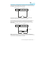
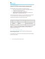
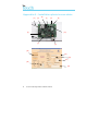
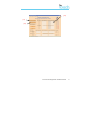
600 Range Dialer
Installation Manual
Version 1.0
The information contained is supplied without liability for any errors or
omissions. No part may be reproduced or used except as authorised by contract
or other written permission. The copyright and foregoing restriction on
reproduction and use extend to all media in which the information may be
embedded.
© 2008 Chiron Technology Ltd
Contents
1.
Introduction ...................................................................................................... 1
1.1. About this manual… .............................................................................. 1
1.2. Overview ................................................................................................ 1
1.3.
System specifications ............................................................................ 3
2.
Before you start… ............................................................................................ 4
2.1. Package contents .................................................................................. 4
2.2. Pre-requisites ......................................................................................... 4
3.
4.
Indicators.......................................................................................................... 5
Installation for pin alarms................................................................................. 6
4.1.
4.2.
4.3.
5.
6.
Installation for use with Galaxy panels............................................................ 9
5.1. Installation .............................................................................................. 9
5.2. Configuration.......................................................................................... 9
5.3.
Post Configuration Tests ..................................................................... 11
5.4.
5.5.
Trouble Reporting ................................................................................ 11
Galaxy Alarm Panel Management ...................................................... 11
Installation with Texecom panels .................................................................. 12
6.1. Installation ............................................................................................ 12
6.2. Configuration........................................................................................ 13
6.3.
6.4.
7.
8.
Installation .............................................................................................. 6
Configuration.......................................................................................... 8
Post Configuration Tests ....................................................................... 8
Post Configuration Tests ..................................................................... 13
Alarm Panel Management ................................................................... 14
Relay outputs ................................................................................................. 15
Troubleshooting ............................................................................................. 15
Appendix A – Installation photo/screen shots ...................................................... 16
Appendix B – Specification ................................................................................... 18
Iris Touch 600 Range Dialer Installation Manual
i
ii
Iris Touch 600 Range Dialer Installation Manual
1.
Introduction
1.1.
About this manual…
This manual is designed to help you, the Installer, with the installation process
for the IRIS Touch alarm dialer. We recommend that you read through this
manual, in its entirety, before you visit the customer’s site and begin the
installation.
1.2.
Overview
The IRIS range of alarm dialers allow users to migrate intruder alarm systems
away from traditional PSTN communications to IP based and/or wireless
networks, without the need to upgrade or replace the alarm system.
The majority of intruder alarm systems which are configured to make alarm calls
to a central monitoring station use the traditional PSTN analogue network as the
communications path. However, PSTN is becoming increasingly unsuitable as
users move to IP and Voice over IP (VoIP) for their fixed networks or rely purely
on mobile (GSM and GPRS) communications. In addition most PSTN service
providers are migrating to VoIP networks, so in the not too distant future PSTN
lines may be withdrawn.
The IRIS dialer range is unique in offering a quick and cost effective way to
interface any existing alarm system to alternative networks such as GSM,
Ethernet and GPRS. As a result of the flexibility and power of IRIS it has
become the IP transmission system of choice for Monitoring Centres across
Europe.
The IRIS 600 series is a PCB format unit intended to be used in the following
situations:
•
The alarm panel can communicate with the IRIS card via a
serial/RS485 interface on the IRIS. This includes panels such as
Honeywell Galaxy and Texecom Premier.
•
The requirements for alarm signalling is limited to 4 pin inputs – e.g. fire
systems or cash machines.
Iris Touch 600 Range Dialer Installation Manual
1
There are two dialers in the range:
•
•
IRIS Touch 620 - Ethernet
IRIS Touch 640 - Ethernet & GPRS
The IRIS Touch dialer should be located within the alarm panel tamper
protected enclosure and powered from the alarm panel battery backed power
supply.
2
Iris Touch 600 Range Dialer Installation Manual
1.3.
System specifications
Feature
Touch 620
Ethernet
Touch 640
Ethernet &
GPRS
Serial data connection for direct
connection to alarm panel
RS485 data connection for direct
connection to alarm panel
Alarm transmission and panel
upload/download via serial or
RS485 connection
Support for SIA (1-3), Contact ID,
and Scancom (Fast Format)
Secure polling (monitoring) over
Ethernet
Secure alarm transmission over
Ethernet
Pin inputs for alarm messages
over Ethernet
4
4
Configuration and diagnostics over
Ethernet
Secure polling (monitoring) over
GPRS
Secure alarm transmission over
GPRS
Pin inputs for alarm messages
over GPRS
4
Configuration and diagnostics
over GPRS
Relay contact outputs
2
Pin inputs for alarm messages
over SMS
2
4
USB port for local configuration
9-30V DC power from alarm panel
Iris Touch 600 Range Dialer Installation Manual
3
2.
Before you start…
2.1.
Package contents
In this package you should have the following components:
•
•
•
•
2.2.
Main dialer PCB with four self-adhesive feet
Ethernet cable (cream) for connection to IP network.
Antenna for GSM/GPRS. (Ethernet & GPRS only).
Installation manual.
Pre-requisites
Prior to installation, you must ensure you have the following:
4
•
•
The IP address for the Monitoring Centre.
•
The type of IP address (either automatic or fixed) for the installation
site. If the site has a fixed IP address, you should get this information
from the customer in advance, together with the Gateway Address and
the Subnet Mask for the IRIS dialer.
•
An additional long Ethernet cable, in case the installation site requires
one longer than that supplied with the IRIS dialer.
•
A SIM card enabled for GPRS with the PIN code clear. (Ethernet &
GPRS only.)
•
The GPRS Access Point Name (APN) of the SIM card provider. Some
networks also require a User Name and Password which can also be
obtained from the SIM card provider. (Ethernet & GPRS only.)
Confirmation that the Monitoring Centre is set up and ready for the
account number or name to be used for this IRIS dialer.
Iris Touch 600 Range Dialer Installation Manual
3.
Indicators
The IRIS Touch dialers have LED indicators [1] that have the functions
described below:
Name
Function
ETH
On when Ethernet connected and synchronised
GPRS
On when GSM registered (Ethernet & GPRS only.)
POLL
On when successfully polling with Monitoring Centre. Note – flickers
off to show each poll
SERIAL
0 .2s on 0.2s off to show not communicating with panel
1.5s on 1.5s off to show dialer not configured
0.1s on 0.9s off to show normal communications
SYS
Flashes 0.5s on 0.5s off to show dialer operational
Iris Touch 600 Range Dialer Installation Manual
5
4.
Installation for pin alarms
The IRIS Touch has PIN inputs that can be used to generate alarm messages.
These can be:
•
•
•
Text messages via SMS ((Ethernet & GPRS only.)
SIA alarm messages over IP to the Monitoring Centre.
Fast Format alarm messages over IP to the Monitoring Centre.
Note - these pin alarm inputs can also be used when the dialer is directly
connected to an alarm panel via the serial or RS485 connections.
4.1.
Installation
Install the IRIS Touch inside the existing alarm panel enclosure and fix with the
self-adhesive feet.
Plug the Ethernet cable between the socket [2] on the IRIS and the local IP
router or socket that has been allocated for the IP connection.
Connect the antenna to the PCB [3]. (Ethernet & GPRS only.)
Fit the SIM card [4] (Ethernet & GPRS only.)
Power must not be applied to the PCB while the SIM card is being
fitted or removed or it may be damaged.
Connect power from the panel’s battery backed supply to the IRIS Touch power
connection terminals [7].
Check the following:
The Ethernet LED is on steady to show Ethernet connected.
6
The GPRS LED goes steady to show GSM registered. (Ethernet &
GPRS only.)
Iris Touch 600 Range Dialer Installation Manual
Each PIN input [5] is designed to be connected in a loop via an open/close
contact source from an alarm panel, or other device, to a reference ground PIN
[6] available on the IRIS dialer, as shown below:
Reference ground
Pin inputs
1
4
Opening the contact (i.e. loop is open circuit) generates an alarm signal.
Closing the contact generates the equivalent restore signal.
It is also possible to link the contacts to the IRIS dialer via sense resistors so
that an open or short circuit tamper on the loop can be detected and the
Monitoring Centre alerted. In this case the connections should be made as
shown below:
Pin inputs
Reference ground
1
4
4K7 Resistor
15K Resistor
Note: For this feature to work correctly it is essential that the resistors are
connected at the contact end of the loop and not the dialer end. The Monitoring
Centre must also enable this facility on the dialer.
Iris Touch 600 Range Dialer Installation Manual
7
4.2.
Configuration
Configuration is performed via Chiron’s IRIS Dialer Configuration software
running on a PC or Laptop connected to the dialer via the USB interface.
Parameters that should be configured on the Networks page are:
Unit account number/name, as provided by the Monitoring Centre [11]
IP address of the Monitoring Centre [12]
IP address for the dialer (if fixed, not DHCP) [13]
APN (and optionally User Name and Password) as provided by the
GPRS operator [14] (Ethernet & GPRS only.)
Click on Update with Shown Settings [15] and check that the POLL LED comes
on to show that the Dialer is communicating with the monitoring centre.
The default SIA messages for each PIN are shown below.
Pin
‘Set’ message
‘Restore’ message
Meaning
1
NBA01
NBR01
Burglary alarm/restore
2
NFA02
NFR02
Fire alarm/restore
3
NQA03
NQR03
Emergency alarm/restore
4
NOP04
NCL04
Open/close
These can be changed from the Alarms page, by clicking on Retrieve Current
Settings [17], making the modifications required [18], and then clicking on
Update with Shown Settings [19].
4.3.
Post Configuration Tests
Carry out tests on all the alarm inputs to make sure the Monitoring Centre
receives the signals correctly.
If using GPRS backup, disconnect the Ethernet cable and check that the signals
are still received correctly.
8
Iris Touch 600 Range Dialer Installation Manual
5.
Installation for use with Galaxy panels
5.1.
Installation
Install the IRIS Touch inside the existing alarm panel enclosure and fix with the
self-adhesive feet.
Plug the Ethernet cable between the socket [2] on the IRIS and the local IP
router or socket that has been allocated for the IP connection.
Connect the antenna to the PCB [3]. (Ethernet & GPRS only.)
Fit the SIM card [4] (Ethernet & GPRS only.)
Power must not be applied to the PCB while the SIM card is being
fitted or removed or it may be damaged.
Connect to Galaxy bus using either a standard Galaxy jumper cable to the 4 pin
header connector [8] or wires to the connector block [7].
Turn on power to panel.
Check the following:
5.2.
The SERIAL LED shows Not Configured (1.5s on, 1.5s off) or Normal
(.1s on .9s off) to confirm dialer is communicating with the panel.
The Ethernet LED is on steady to show Ethernet connected.
The GPRS LED goes steady to show GSM registered. (Ethernet &
GPRS only.)
Configuration
The IRIS Touch can be configured from Galaxy keypad – but note that for
GPRS it is not possible to configure the settings (e.g. APN ) from the Galaxy
keypad as the galaxy has no entry method.
Iris Touch 600 Range Dialer Installation Manual
9
The APN can be configured via an SMS message from any mobile phone or via
the IRIS Dialer Configuration Software running on a PC or Laptop connected to
the dialer via the USB interface.
The configuration menu on the Galaxy panel for the Ethernet card is found at
location 56 (Communications) entry 4 (Ethernet).
If the IRIS Dialler is not set to defaults, default it by clearing the Primary IP
address on the Galaxy (menu 02 entry 2). Check that the SERIAL LED is
showing Not Configured.
If GPRS is used, set the GPRS APN. This cannot be done from the Galaxy
keypad as there is no APN menu entry. As an alternative, send a text message
to the phone number of the SIM card being used. The text should be in the
format:
AT%G10=’apn’
Where ‘apn’ is the APN name, e.g. orangeinternet
Alternatively, the information can be set via the Networks page of the IRIS
Dialer Configuration software [14].
Fixed IP address only - set the IP address, subnet mask and gateway address
on the Galaxy keypad menu 01 (Module Configuration). The Site Name
parameter is not required.
In the Alarm Report menu (02) set:
•
•
•
•
Alarm format required (e.g. SIA) (entry 1)
IP address of Monitoring Centre in Primary IP (entry 2). Note Port
Number is not required.
Account number (entry 4)
Note – other menu entries are not used and need not be set.
Make an Engineer Test call (menu 05). The parameters entered will be sent
from the panel to the dialer and polling to the Monitoring Centre will start.
Check that the POLL LED comes on.
10
Iris Touch 600 Range Dialer Installation Manual
5.3.
Post Configuration Tests
Carry out alarm signaling tests to make sure the Monitoring Centre receives the
signals correctly.
If using GPRS backup, disconnect the Ethernet cable and check that the signals
are still received correctly.
5.4.
Trouble Reporting
The IRIS dialer will report the following trouble conditions to the Galaxy panel:
•
Line Fail – if polling via Ethernet or GPRS is not successful.
•
Fail to Communicate if an alarm is not transmitted successfully after 10
attempts.
5.5.
Galaxy Alarm Panel Management
The IRIS adapter acts as a conduit for remote configuration of the Galaxy panel
and remote keypad operation using Honeywell’s RSS software running with
direct IP connection on the PC.
Incoming and outgoing calls are supported.
Incoming calls (from RSS) are initiated using the fixed IP address set for the
adapter and the default Galaxy port number 10001.
Outgoing calls are initiated from the IRIS Polling Engine using the IRIS Remote
Data Call function to the IP address of the PC running the RSS software.
Iris Touch 600 Range Dialer Installation Manual
11
6.
Installation with Texecom panels
6.1.
Installation
Install the IRIS Touch inside the existing alarm panel enclosure and fix with the
self-adhesive feet.
Plug the Ethernet cable between the socket [2] on the IRIS and the local IP
router or socket that has been allocated for the IP connection.
Connect the antenna to the PCB [3]. (Ethernet & GPRS only.)
Fit the SIM card [4] (Ethernet & GPRS only.)
Power must not be applied to the PCB while the SIM card is being
fitted or removed or it may be damaged.
Connect to a panel serial port bus using a straight-through one-one jumper
cable.
Turn on power to panel .
Check the following:
12
The SERIAL LED shows Not Configured (1.5s on, 1.5s off) or Normal
(.1s on .9s off) to confirm dialer is communicating with the panel – note
that this may take a few minutes after power up.
The Ethernet LED is on steady to show Ethernet connected.
The GPRS LED goes steady to show GSM registered. (Ethernet &
GPRS only.)
Iris Touch 600 Range Dialer Installation Manual
6.2.
Configuration
Configuration is through the panel keypad under the UDL/Digi options menu,
according to Texecom’s instructions.
If GPRS is used, first set the GPRS APN. This cannot be done from the
Texecom keypad as there is no APN menu entry. As an alternative, send a text
message to the phone number of the SIM card being used. The text should be
in the format:
AT%G10=’apn’
Where ‘apn’ is the APN name, e.g. orangeinternet
Alternatively, the information can be set via the Networks page of the IRIS
Dialer Configuration software [14].
In the Setup Modules sub menu select Setup IP Data and define:
IP address, Gateway address and Net Mask of the dialer (if fixed IP
address used)
Port number to be used for communications with Wintex
Polling IP address of the Monitoring Centre
Dialer name
Modem speed is set to 19200
In the Com Port Setup sub menu, make sure the com port used to connect to
the dialer is set as IRIS IP Module.
6.3.
Post Configuration Tests
Carry out alarm signaling tests to make sure the Monitoring Centre receives the
signals correctly.
If using GPRS backup, disconnect the Ethernet cable and check that the signals
are still received correctly.
Iris Touch 600 Range Dialer Installation Manual
13
6.4.
Alarm Panel Management
The IRIS adapter acts as a conduit for remote configuration of the panel and
remote keypad operation using Texecom’s Wintex software running with direct
IP connection on the PC.
Incoming and outgoing calls are supported.
Incoming calls are initiated using the fixed IP address set for the adapter and
the port number set on the panel and in Wintex.
Outgoing calls are initiated from the IRIS Polling Engine using the IRIS Remote
Data Call function to the IP address of the PC running the Wintex software.
14
Iris Touch 600 Range Dialer Installation Manual
7.
Relay outputs
The IRIS dialer has two relay outputs [10] that can be used in a number of
ways:
•
•
•
To indicate communications path failure.
Activation by incoming SMS Message.
Setting by the Monitoring Centre.
The relay contacts are normally open and closed when activated.
Wire to these contacts as required and define how they are to be used using the
configuration software [16].
8.
Troubleshooting
Problem
Resolution
No LED activity display when
IRIS dialer is connected to the
power.
Check that there is power to the system
and that the wiring is the correct polarity.
Serial LED flash pattern
indicates no connection to
panel
Alarm panel serial/RS485 interconnect
fault.
Iris Touch 600 Range Dialer Installation Manual
15
Appendix A – Installation photo/screen shots
[3]
[8]
[4]
[1]
[5]
[6]
[10]
[9]
[7]
[2]
[15]
[11]
[12]
[13]
[16]
[14]
16
Iris Touch 600 Range Dialer Installation Manual
[18]
[17]
[19]
Iris Touch 600 Range Dialer Installation Manual
17
Appendix B – Specification
Alarm Dialer Interface
Direct connection to various panel types:
Honeywell Galaxy (V4.00 onwards) (via RS485)
Texecom Premier (V7.60 onwards) (via serial)
RS485 2 wire half duplex
Serial data – 3V logic levels (5V tolerant), Tx, Rx, Ground
Ethernet Interface
10Mbps and 100Mbps (10/100BaseT) with auto-negotiation
UTP with standard RJ45 socket for CAT-5 cabling
Dynamic IP addressing (DHCP) or fixed
GSM/GPRS Interface
Dual band GSM 900 MHz and DCS 1800 MHz
MMCX socket for antenna connection
IP
TCP ports (outbound): 51292 (diagnostics), 52737 (polling), 53165 (alarms)
PIN Inputs
Maximum input voltage range
0V to +24V
Input ‘low’ threshold
< 2V
Input ‘high’ threshold
> 3V
Input pull-up impedance
Internal 10K to 5V supply
Relay Outputs
Maximum operating voltage
24V
Maximum current rating
1A
Power Supply
Supply voltage
9 - 30V DC
Ethernet only (typical current)
145mA (supply at 12v)
With GSM/GPRS (typical current)
185mA (supply at 12V)
Note: These figures are based upon the Ethernet link being connected. With GSM/GPRS there will
also be additional transient peak current of up to 250mA required as GSM and GPRS transmissions
(e.g. for network registration and calls) are made.
Weights
Dialer unit
60g
Fully packaged
160g
18
Iris Touch 600 Range Dialer Installation Manual
Conformance
The IRIS range of alarm dialers comply with the following European Directives:
•
•
•
1999/5/EC (Radio & Telecoms Terminal Equipment Directive).
72/23/EEC (Low Voltage Directive).
89/336/EEC (Electromagnetic Compatibility Directive as amended by
92/31/EEC).
Conformance to EN50131 and EN50136
The IRIS dialers are compatible with the requirements of European standards
prEN50131-1 (Alarm Systems – Intrusion and hold-up systems Part 1: System
Requirements) (dated Feb 2004) and EN50136-1-1 (Alarm Systems – Alarm
transmission systems and equipment) (January 1998 with Amendment 1 August
2001) as follows:
•
•
The IRIS dialers conform to Environmental Class II.
The IRIS dialers are compliant to ATS 6 compatible with Security
Grade 4.
Safety
Care should be taken when interconnecting telecommunications equipment that
only like interfaces are interconnected to avoid safety hazards.
SELV:
SELV (Safety Extra-Low Voltage) is defined as a secondary circuit
which is so designed and protected that under normal and single fault
conditions the voltage between any two accessible parts does not
exceed a safe value (42.4V peak or 60V dc maximum).
The interfaces on the IRIS dialer have the following safety classifications:
•
Data Interface: SELV suitable for connection to the SELV interface on a
data terminal such as a PC COM port.
•
•
Power Interface: SELV for connection to a DC supply.
Inputs and Outputs: SELV for connection to alarm output and input
pins.
Iris Touch 600 Range Dialer Installation Manual
19