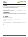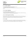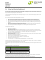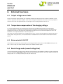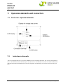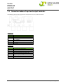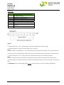
1
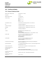
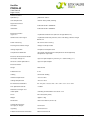
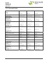
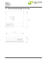
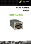
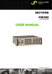
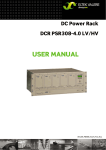
RECTIFIER PSR06-W USER MANUAL UM_PSR06-W_E_R2.0 Notes to this manual Rectifier PSR06-W User Manual Page 2 (24) ATTENTION! Read this manual very carefully before installing and commissioning the specified module. This manual is a part of the delivered module. Familiarity with the contents of this manual is required for installing and operating the specified module. The rules for prevention of accidents for the specific country and the general safety rules in accordance with IEC 364 must be observed. The function description in this manual corresponds to the date of publishing. Technical changes and changes in form and content can be made at any time by the manufacturer without notice. There are no obligations to update the manual continually. The module is manufactured in accordance with applicable DIN and VDE standards such as VDE 0106 (part 100) and VDE 0100 (part 410). The CE marking on the module confirms compliance with EU standards 2006-95-EG (low voltage) and 2004-108-EG (electromagnetic compatibility) if the installation and operation instructions are followed. Supplier: FAX Email Internet Eltek Valere Deutschland GmbH GB Industrial Schillerstraße 16 D-32052 Herford + 49 (0) 5221 1708-210 + 49 (0) 5221 1708-222 [email protected] http://www.eltekvalere.com Changes and errors excepted. Copyright ELTEK VALERE DEUTSCHLAND GmbH 2009. All rights reserved. ELTEK VALERE DEUTSCHLAND ©2009 UM_PSR06-W_E_R3.0 Rectifier PSR06-W User Manual Page 3 (24) Revision history: Revision: 3.0 Date: 2011-01-17 Revision 00 1.0 Description of change Writer Reworked edition on base of the further manual “BHB-PSR06-W.D25RTH 1000.HB101”: Layout changed, several minor text corrections New revision status numbering (X.X) introduced, values for input RTH voltage range changed (>>wide input range). Date 2008-02-14 2009-04-08 1.1 Minor text modifications RTH 2009-04-16 2.0 Several minor corrections inserted. RTH 2010-03-23 3.0 Section 6, and 7.3 as well modified. RTH 2011-01-17 ELTEK VALERE DEUTSCHLAND ©2009 UM_PSR06-W_E_R3.0 Rectifier PSR06-W User Manual Page 4 (24) Contents A. SAFETY INSTRUCTIONS............................................................................................................................................................5 B. ELECTRONIC WASTE DISPOSAL ..............................................................................................................................................5 1. GENERAL INFORMATION .....................................................................................................................................................6 2. TYPE RANGE..........................................................................................................................................................................6 3. START UP PROCEDURE.......................................................................................................................................................7 4. OPERATION............................................................................................................................................................................7 5. FUNCTIONS............................................................................................................................................................................8 5.1 Circuit diagram..........................................................................................................................................................8 5.2 5.2.1 5.2.2 5.2.3 5.2.4 5.2.5 5.3 5.3.1 5.3.2 5.3.3 5.3.4 5.3.5 5.3.6 5.4 Electrical function description..............................................................................................................................9 Electrical insulation..........................................................................................................................................9 Input.....................................................................................................................................................................9 Output .................................................................................................................................................................10 Dynamic regulation of output voltage ........................................................................................................10 RFI suppression.......................................................................................................................................................10 Monitoring ..................................................................................................................................................................10 Mains voltage monitoring ...............................................................................................................................10 Operation monitoring.......................................................................................................................................10 Output voltage low ..........................................................................................................................................11 Output voltage high .........................................................................................................................................11 Protection against overheating ....................................................................................................................11 Signals .................................................................................................................................................................11 Output and threshold adjustment.......................................................................................................................12 6. EXTERNAL FUNCTIONS.......................................................................................................................................................13 6.1 Output voltage sensor leads.................................................................................................................................13 6.2 Temperature compensation of the charging voltage.....................................................................................13 6.3 External switch ON/OFF .........................................................................................................................................13 6.4 Boost charge mode (second voltage line) .........................................................................................................13 7. OPERATION ELEMENTS AND CONNECTORS...................................................................................................................14 7.1 Front view / operation elements .........................................................................................................................14 7.2 Indication instruments .............................................................................................................................................14 7.3 Connection tables of input and output terminals............................................................................................15 8. MAINTENANCE......................................................................................................................................................................17 9. FAULT FINDING INSTRUCTIONS.........................................................................................................................................17 9.1. Output voltage failure ............................................................................................................................................17 9.2. Output voltage deviation .......................................................................................................................................17 10. TECHNICAL DATA...........................................................................................................................................................18 10.1. General technical data...........................................................................................................................................18 10.2. Type specific data ...................................................................................................................................................20 11. DIMENSIONAL DRAWINGS/FRONT VIEW ...................................................................................................................21 12. YOUR NOTES ............................................................................................................................................................................22 ELTEK VALERE DEUTSCHLAND ©2009 UM_PSR06-W_E_R3.0 Rectifier PSR06-W User Manual Page 5 (24) A. Safety Instructions Warning! Because several components of operating electrical modules are charged by dangerous voltage, the improper handling of electrical modules may cause accidents involving electrocution, injury, or material damages. Operation and maintenance of electrical modules must be performed by qualified skilled personnel such as electricians in accordance with EN 50110-1 or IEC 60950. Install the module only in areas with limited access to unskilled personnel. Before starting work, the electrical module must be disconnected from mains. Make sure that the module is earthed. Do not touch connector pins as they can be charged with dangerous voltage up to 30 seconds after disconnection. Only spare parts approved by the manufacturer must be used. B. Electronic Waste Disposal The correct disposal of electronic waste is the responsibility to recycle discarded electronic equipment and is necessary to achieve the chosen level to protect human health and the environment. In the case of waste disposal of your discarded equipment we recommend to contact a professional waste management company. ELTEK VALERE DEUTSCHLAND ©2009 UM_PSR06-W_E_R3.0 Rectifier PSR06-W User Manual Page 6 (24) 1. General Information The primary switched mode rectifier type PSR06-W (named SMPS on the next pages) delivers an output power of approx. 600W. Typical applications are DC power supplies and uninterruptable power supply with battery. Rectifiers of type SMPS have good dynamic regulation properties concerning input voltage changes and load variations. It works with an IV characteristic in accordance with DIN 41772 and it is a complete connectable module in a wall cabinet. The operation elements and measurement instruments are located on the front panel, the input/output connectors are located at the bottom of the module. SNT modules also operates single side grounded or ungrounded at input and output. 2. Type Range Type Designation PSR06/ 24-20W Article code Input voltage range (VAC) 120-230 (-15/+10%) Outputvoltage (VDC) 24 Outputcurrent (A) 20 100-006-142.00 48-10W 100-006-152.00 120-230 (-15/+10%) 48 10 60-8.2W 100-006-162.00 120-230 (-15/+10%) 60 8.2 110-4.5W 100-006-172.00 120-230 (-15/+10%) 108 4.5 Available options and accessories: 1) Temperature sensor lead LM 335 (sensor lead in M5 cable shoes with 2m wire); article code: 880-300-TMP.00 2) Temperature sensor lead LM 335 (sensor lead in M5 cable shoes with 4m wire); article code: 880-300-TMP.01 ELTEK VALERE DEUTSCHLAND ©2009 UM_PSR06-W_E_R3.0 Rectifier PSR06-W User Manual Page 7 (24) 3. Start up procedure Before connecting to the input voltage, it should be checked whether the voltage information on the rating plate corresponds to the available voltage and also that the polarity corresponds to the connection plan of the plug. The mains connection is done via terminals below the cabinet. The protective conductor should be generally connected (protection class 1, leakage current 3.5mA). The DC output contact has to be connected on terminal X1. The signalling contacts for monitoring, sense links and active current are to be connected on terminal X2/X3. Important: The rectifier has big capacitors at the output. If you connect a switched off module to a battery or other modules which operate in paralleling, there is a big capacitor charge current. This current may destroy the contacts on output connectors. WARNING! After switching off, the capacitors hold its voltage for several times. Do not touch! The rectifier operates with convection cooling. The ambient temperature has to be less than +55°C. If there is a higher temperature, the life time of the modules will be decreased. The losses per module are approx. 40 to 80W (depends on type). 4. Operation All operation elements are located on the front panel of the module. The function of each element is explained on the following pages. See also the front panel drawing on section 7.1. ELTEK VALERE DEUTSCHLAND ©2009 UM_PSR06-W_E_R3.0 Rectifier PSR06-W User Manual Page 8 (24) 5. Functions 5.1 Circuit diagram FIG. 1: Block Diagram PSR06-W ELTEK VALERE DEUTSCHLAND ©2009 UM_PSR06-W_E_R3.0 Rectifier PSR06-W User Manual Page 9 (24) 5.2 Electrical function description Rectifiers of type PSR consist of the following main parts: 1. Input filter suppressing the feedback of high frequency interference produced by the unit into the mains as well as for the attenuation of the interference voltages and voltage transients superimposed on the mains. 2. Mains rectifier with switched step-up-converter (operation frequency 100kHz) to transform the input voltage in a pre-regulated DC voltage of approx. 380V and to control the waveform of input current (sinusoidal!). An additional function is the limitation of inrush current. 3. Transistor bridge to transform the 380VDC in a pulse width modulated AC voltage with an frequency of 100KHz. 4. HF transformer for decoupling of primary and secondary part and to transport the power to secondary side. 5. Rectifier diodes to make a DC voltage from high frequency AC voltage. 6. LC-Filter to reduce the voltage ripple on rectifier output. 7. Output filter for RFI suppression and to reduce the noise level on DC line. 8. Internal power supply for supplying of primary and secondary control units with potential decoupling. 9. Regulation line with decoupling through opto couplers. 10. Adjustment panel for adjustment of output parameters, signals and measurement instruments. 5.2.1 Electrical insulation Through the construction of the module (also module parts) and separate wiring of mains input and DC output the SMPS fulfils the following standards: devices with UO 60VDC protection against shock current because of low voltage with safe electrical decoupling acc. to EN 60950 and VDE 0100. devices with UO > 60VDC safe electrical decoupling to UO = 220VDC acc. EN 60950 and VDE 0160. 5.2.2 Input A one-pole mains switch is used to switch on and off the unit. The unit is switched on by a run-up stage which limits the switch-on current to <Inom ELTEK VALERE DEUTSCHLAND ©2009 UM_PSR06-W_E_R3.0 Rectifier PSR06-W User Manual Page 10 (24) 5.2.3 Output The output line is an IV characteristic acc. to DIN 41772 /DIN 41773 with factory set decreased charge line (-1% at 100% Inom); with factory set active current sharing as option. The output is continuous short circuit proof (constant current controlling). 5.2.4 Dynamic regulation of output voltage At load jumps between 10 % and 90 % Inom / 90 % and 10 % Inom the dynamic voltage difference is max. ±3 % and will be regulated within max. 1.5ms to static levels. 5.2.5 RFI suppression Modules of type PSR fulfil the standard VDE 0878 T1 and EN 55011/55022 class ‘B’. The output ripple is (measured psophometric acc. to CCITT) < 1,2mV (24V), < 1.8mV (48V and 60V). 5.3 Monitoring 5.3.1 Mains voltage monitoring The SMPS is designed for an operation in the specified range (see technical data sheet). The unit is protected for input voltages up to 270VAC by a varistor at the input-side. 5.3.2 Operation monitoring Functional monitoring; signalling with LED "Vout OK", criterion: output voltage 97 % of adjusted output voltage without constant current regulation and 85 % of adjusted output voltage with constant current regulation. The signalling threshold of this monitoring automatically follows the adjusted nominal output voltage. This signal is included in the collective failure signal of the rectifier. Additional there is an optocoupler signal (VO O.K.) At operation with internal decoupling diodes the voltage before diodes will be measured. ELTEK VALERE DEUTSCHLAND ©2009 UM_PSR06-W_E_R3.0 Rectifier PSR06-W User Manual Page 11 (24) 5.3.3 Output voltage low Output voltage low monitoring; signalling with green LED "Vout>Vmin", Criterion: output voltage is higher than adjusted level V<; This signal has its own relay contact on signalling connector. If the voltage value is O.K. Pin 6 and Pin 7 of X2 are closed. 5.3.4 Output voltage high Output voltage high monitoring; signalling with red LED "Vout>", Criterion: output voltage higher than adjusted level V>; This signal is included in collective failure signal of rectifier. If there is an error the LED is switched ON and the rectifier internally switches OFF. You have to reset the unit by ON/OFF switch. 5.3.5 Protection against overheating Protection against overheating; signalling with blinking red LED "Bell symbol", criterion: temperature of heat sink > 90°C. This protection reduces the output power if the temperature is on the limit. This signal is included in collective failure signal. If the temperature is normally the output power will be increased automatically. 5.3.6 Signals The signals "VO OK", "Mains OK" and "Constant Current Mode Iconst" are opto coupler signals with a loading of 30 V/5mA. The opto couplers switches off at error. The collective failure signal is delayed for approx. 1sec. The relay contacts between Pin 3 and Pin 5 of X2 are open and between Pin 4 and Pin 5 are closed at error. ELTEK VALERE DEUTSCHLAND ©2009 UM_PSR06-W_E_R3.0 Rectifier PSR06-W User Manual Page 12 (24) 5.4 Output and threshold adjustment The adjustment of output values and monitoring thresholds is very easy. All values can be adjusted using the front keys. The values are shown on digital displays. Enabling the 2nd voltage line via an external circuit is necessary to adjust the boost charge voltage VO2 (see section 6.4). In normal operation the top display shows the output voltage (VO1 and VO2) and the bottom display shows the output current (IO). For any adjustment please follow the following instructions: press both keys UP/DOWN () together for a short time; the rectifier changes to adjustment mode press the key UP() or DOWN () to change the adjustment parameter (see also table on bottom) press both keys UP/DOWN () together for a short time; the rectifier changes to value change mode press the key UP() or DOWN () to change the adjustment value (if you hold the key the value changes quicker) press both keys UP/DOWN () together for a short time; the rectifier changes back to the adjustment mode (at this moment the changed value will be stored) press both keys UP/DOWN () for approx. 3 sec. to change back to the operation mode The adjustment mode is for: Adjustment of voltage VO1: Normal operation; adjust voltage using potentiometer UO1 to correct value (shown at the top display) Adjustment of voltage VO2: Switch over the unit to VO2-line by external switch (look chapter 6 for correct connecting of signal connector); adjust voltage using potentiometer VO2 to correct value (shown at the top display) Adjustment of monitoring threshold V<: Adjust voltage using potentiometer V< to correct value and measure this value at measurement sockets U< in front of the unit Adjustment of monitoring threshold V>: Adjust voltage using potentiometer V> to correct value and measure this value at measurement sockets V> in front of the unit Adjustment of the current limit Iconst: The current limit Iconst is adjusted using the potentiometer Iconst by external load. The measured value at the measure bushings V> and V< corresponds to V/cell for 2 cells, i.e. there is a voltage of 4.8V at the measure bushing for adjusting the V> to 2.4 V/cell. The adjustment ranges and the adjustments in the factory should be picked up from the respective technical data sheet. Adjustable parameters in adjustment mode: Display Vo1 (=UA1) Vo2 (=UA2) Io (=IA) V< V> t Parameter triple charge voltage boost charge voltage (look also cap. 6.4) output current output voltage low threshold (look also cap. 5.3.3) output voltage high threshold (look also cap. 5.3.4) coefficient of temperature for temperature compensation of charge voltage (look also cap. 6.2) The monitoring thresholds automatically follow the adjusted nominal values of output voltage. The monitoring thresholds for mains/step-up-converter and over heating are not changeable. Details about the adjustment ranges of several threshold values, see section “Technical Data”. ELTEK VALERE DEUTSCHLAND ©2009 UM_PSR06-W_E_R3.0 Rectifier PSR06-W User Manual Page 13 (24) 6. External Functions 6.1 Output voltage sensor leads Using sense links for output voltage you are able to compensate voltage losses due to wires and diodes as well. The max. regulation difference is approx. 4% of nominal voltage. Interruption on sense links, confusing of poles or short circuit can not damage the rectifier. At interrupt it can be a voltage increase of max. 4%. 6.2 Temperature compensation of the charging voltage At using of closed batteries we recommend the temperature controlled compensation of charge voltage. You have to connect an external active temperature sensor (option) on signalling connector. The coefficient of temperature is normally -4mV/K per cell (at temperature range of 0-50 °C). The basic temperature is 20°C. The coefficient can be adjusted between -1 to -6mV/K per cell. The sensor has to be connected using a 2-pole wire (0.25 mm2). It can be mounted directly on top of battery or on battery poles. At big distances (> 2m) we recommend a shielded wire with connection of the shield on rectifiers ground. 6.3 External switch ON/OFF The rectifier can be externally switched off by switching pin 2 of connector terminal X3 to GND according to section 7.3. In this case, the switch-off does not result in a collective failure signal! 6.4 Boost charge mode (second voltage line) A second voltage line (e.g. boost charge voltage) can be enabled at the PSR06W. To enable the second voltage line you have to connect Minus (GND) to pin 1 of connector terminal X3 (see section 7.3) using an external switch. The voltage value "VO2" can be adjusted by the user (see section 5.4). ELTEK VALERE DEUTSCHLAND ©2009 UM_PSR06-W_E_R3.0 Rectifier PSR06-W User Manual Page 14 (24) 7. Operation elements and connectors 7.1 Front view / operation elements 7.2 Indication instruments The unit is equipped with LED- instruments 0-999 for current and voltage indication. The accuracy corresponds to Class 1 with reference to the nominal output value of the unit. The indication instrument can be converted to the indication of the adjusted theoretical value for the regulation and monitoring via an external circuit of the signal plug. ELTEK VALERE DEUTSCHLAND ©2009 UM_PSR06-W_E_R3.0 Rectifier PSR06-W User Manual Page 15 (24) 7.3 Connection tables of input and output terminals The following picture shows the terminal area (terminal X1, X2, X3) of the rectifier: Terminal X1: X1/Pin 1 2 3 4 5 6 7 Function DC – Output L+ DC – Output L+ DC – Output LDC – Output LPE N - Input L1 - Input Terminal X2: X2/Pin 1 2 3 4 5 6 7 8 Function (+) Sensor lead connection6) Not connected Signal relay general fault alarm, NO Signal relay general fault alarm, NC Signal relay general fault alarm COM 5) Signal relay U<,COM 5) Signal relay U< (total discharge), NO (-) Sensor lead connection6) ELTEK VALERE DEUTSCHLAND ©2009 UM_PSR06-W_E_R3.0 Rectifier PSR06-W User Manual Page 16 (24) Terminal X3: X3/Pin 1 2 3 4 5 6 7 8 9 Function Control input for the second voltage line VO2 (boost charge) 1) (+) External On/Off 4) Optocoupler common emitter Optocoupler C ” UO present” +15V DC Optocoupler C "IO" Temperature sensor lead (+) 2) Compensating connection for current distribution 3) GND Legend: 1) The connection of Pin 1 to -VO (GND) enables the second voltage line (e.g. boost charge). 2) Connection of the TK sensor by two-core cable to pin 7 and pin 9. Note: If several modules are paralleled, pin 7 of each individual unit and pin 9 of each individual unit has to be connected. 3) At active current sharing mode of paralleled units pin 8 and 9 respectively of each module has to be connected. 4) The connection of Pin 2 to -VO (GND) switches the rectifier (externally) OFF (see the picture above). Note: The input is potential free with safe electrical decoupling to primary side and with 500VDC to secondary side. 5) The relay outputs are potential free with safe electrical decoupling to primary side and with 500VDC to secondary side. 6) ATTENTION! If you have decoupling diodes in minus at output side the use of sensor leads is not allowed. ELTEK VALERE DEUTSCHLAND ©2009 UM_PSR06-W_E_R3.0 Rectifier PSR06-W User Manual Page 17 (24) 8. Maintenance Due to the implemented components, the SMPS unit virtually is maintenance free. In case of operation in dusty atmosphere, it is regularly advisable to control the dust inside of the unit and, if necessary, blow it out with compressed air. Deposits of dust can result in reduced cooling and could also result in conductive impurities in combination with dew formation or high moisture. 9. Fault finding instructions Only skilled and trained technical personnel should carry out all necessary operations at the unit. 9.1. Output voltage failure - Input voltage present? Mains switch on? Is the input plug correctly inserted? Output terminal polarised or short-circuit at the output? Parallel operation condition: external decoupling diode polarised? Monitoring VO > responded (LED VO> lights up)? >>Corrective action: Switch the unit ON/OFF and examine the adjustment VO >! If the unit still does not work even though all checks have been done, contact your sales agent or the ELTEK VALERE INDUSTRIAL service department. 9.2. Output voltage deviation - Does the unit operate in the current limit due to overload? Corrective action: Reduce the load! Adjustment value of VO correct? Corrective action: Readjust the output voltage. If external sensors lead connection is used: is the sensor lead connection open? Are the decoupling diodes connected in the output circuit? >>Corrective action: Correct the potential drop by increasing the output voltage of the unit! If the unit still does not work even though all checks have been done, contact your sales agent or the ELTEK VALERE DEUTSCHLAND service department. ELTEK VALERE DEUTSCHLAND ©2009 UM_PSR06-W_E_R3.0 Rectifier PSR06-W User Manual Page 18 (24) 10. Technical Data 10.1. General technical data Nominal input voltage range 120-230VAC (-15/+10%) Frequency 47-63Hz Nominal input current 2,7A @ 230VAC Power Factor 0.99: 100%>Pnom > 50%; 0.97: 50%> Pnom > 25%; 0.95: Pnom < 25%; Characteristic curve IV characteristic according to DIN 41 772/ DIN 41773 RFI according to EN50081-1 Conduction related according to EN55011 / EN55022 limit value class "B" Radiation according to EN 55011 / EN55022 limit value class "B" EMC according to EN50082-2 Cabinet ESD-test according to EN61000-4 part 2; 6kV contact; 8kV air discharge HF-field according to EN61000-4 part 3; 10V/m (30MHz - 1GHz) Power cable Burst-test according to EN61000-4 part 4; 2kV Surge-test according to EN61000-4 part 5; 4kV unsymmetrical; 2kV symmetrical Control cable Burst-test according to EN61000-4 part 4; 2kV Surge-test according to EN61000-4 part 5; 2kV unsymmetrical Function extra low voltage with safe insulation for UO 60VDC according to VDE0100 part 410/11.83, Section. 4.3.2 Dynamic behaviour 3 % for load steps between 10% - 90% - 10% nominal output current (transient time t 1 ms) Short circuit behaviour sustained short circuit-proof, 1 x nominal output current Function monitoring „VO1“ threshold value floating (green LED “Vout OK”) UO 97% of the adjusted output voltage without current limit or UA 85% of the adjusted output voltage Monitoring output undervoltage „U<„ green LED „Vout>Vmin“, with potential-free contact Monitoring output overvoltage „U>„ red LED “Vout>” ELTEK VALERE DEUTSCHLAND ©2009 UM_PSR06-W_E_R3.0 Rectifier PSR06-W User Manual Page 19 (24) Constant current operation „IO“ yellow LED “Iconst” Over-temperature red LED “bell symbol”, blinking Digital instruments: Ammeter: Indication of 00.1 to 99.9ADC Voltmeter: Indication of 00.1 to 999VDC External functions: Signal “V<” via potential-free contact (contact charge: 60VDC/1A) General fault alarm signal via potential-free relay contact (1sec. time delay); contact charge: 60VDC/1A Power measuring for active current sharing Discharge test/boost charge voltage value adjustable Voltage regulation Temperature compensated Temperature coefficient 4mV/K per cell with external temperature sensor (optional); temperature adjustable External sensor lead connection for output voltage “VO“ Signal via opto coupler VO present („VO1“ alternatively „VO2“) constant current operation “IO“ Signal via opto coupler External ON/OFF Design Wall cabinet Protection class IP 20 Cooling Convection cooling Ambient temperature -20°C to +45°C Storage temperature -40°C to + 85°C Environmental conditions IEC 721 part 3-3 Class 3K3 / 3Z1 / 3B1 / 3C2 / 3S2 / 3M2 Max. operation altitude <1500m Mechanical strength and Shock-proof according to VDE 0160 issue 5.88 Pt. 7.2.2 Finish RAL 7035 (front plate) Weight approx. 5.3kg Dimensions 280 x 285 x 95mm (H x W x D) Connection terminals: AC-Input, DC-Output Terminal X1 Signalling Terminal X2/X3 Protective conductor connection Bolt M4/Terminal X1 ELTEK VALERE DEUTSCHLAND ©2009 UM_PSR06-W_E_R3.0 Rectifier PSR06-W User Manual Page 20 (24) 10.2. Type specific data Type: PSR06/ 24-20W Article code: 100-006-142.00 Output Voltage VO1 (Equalising charge) Adjusted value 27.2VDC ± 1 % Adjustment range 23.4 to 28.8VDC Output voltage VO2 (Boost charge) Adjusted value 28.8VDC ± 1 % Adjustment range 24 to 30VDC Output current IO Adjusted value 20ADC ± 2 % Adjustment range 50-100% Inominal Type of battery Lead acid battery, 12 cells Efficiency 88 % Voltage ripple 20mVpp Noise voltage according to CCITT 1.2mV Monitoring: DC under voltage V< Threshold value 20.4VDC Adjustment range 19.2 to 24VDC DC over voltage V> Threshold value 30VDC Adjustment range 26 to 30VDC ELTEK VALERE DEUTSCHLAND ©2009 48-10W 60-8.2W 110-4.5W 100-006-152.00 100-006-162.00 100-006-172.00 54,5VDC ± 1 % 68.1VDC ±1% 122.6VDC ±1% 46,6 bis 57,6VDC 58.5 to 72.0VDC 105 to 130VDC 57.6VDC ± 1 % 72.0VDC ± 1 % 129.6VDC ±1% 48 to 60VDC 60 to 73VDC 108 to 135VDC 10ADC ± 2 % 8.2ADC ± 2 % 4.5ADC ± 2 % 50-100% Inominal 50-100% Inominal 50-100% Inominal 24 cells 30 cells 54 cells 89 % 89 % 89 % 20mVpp 20mVpp 100mVpp 1.8mV 1.8mV --- 40.8VDC 51.0VDC 91.8VDC 38.4 bis 48VDC 48 bis 60VDC 86.4 bis 108VDC 60VDC 75VDC 135VDC 52 to 60VDC 66 to 75VDC 119 to 135VDC UM_PSR06-W_E_R3.0 Rectifier PSR06-W User Manual Page 21 (24) 11. Dimensional Drawings/Front View ELTEK VALERE DEUTSCHLAND ©2009 UM_PSR06-W_E_R3.0 Rectifier PSR06-W User Manual Page 22 (24) 12. Your Notes ELTEK VALERE DEUTSCHLAND ©2009 UM_PSR06-W_E_R3.0 Rectifier PSR06-W User Manual Page 23 (24) ELTEK VALERE DEUTSCHLAND ©2009 UM_PSR06-W_E_R3.0 Supplier: FAX Email Internet Eltek Valere Deutschland GmbH GB Industrial Schillerstraße 16 D-32052 Herford + 49 (0) 5221 1708-210 + 49 (0) 5221 1708-222 [email protected] http://www.eltekvalere.com Copyright ELTEK VALERE DEUTSCHLAND GmbH 2009. All rights reserved.