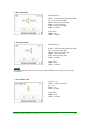
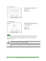
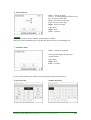
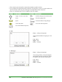
1
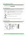
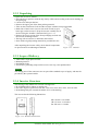
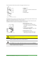
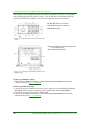
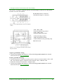
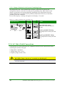
THEIA™ HE-t String Inverter ~ 2.0 - 4.4 kWAC, 600 VDC INSTALLATION GUIDE www.eltekvalere.com/renewable Information in this document is subject to change without notice and does not represent a commitment on the part of Eltek Valere. No part of this document may be reproduced or transmitted in any form or by any means — electronic or mechanical, including photocopying and recording — for any purpose without the explicit written permission of Eltek Valere. Copyright ©: Eltek Valere, 2011 357115.033 NS-EN ISO 14001 Certified NS-EN ISO 9001 Certified Certificate No: 11276-2007-AE-NOR-NA Certificate No: 4072-2007-AQ-NOR-NA Issue 2.0, 2011 March Published 2011-02-20 IngBjoNo II Installation Guide THEIA HE-t String Inverters 357115.033, Issue 2.0, 2011 March Contents 1. Product Overview ......................................................................................................................... 4 1.1. Symbols Used ........................................................................................................ 4 1.2. Product Label......................................................................................................... 4 1.3. Unpacking and Inspection ..................................................................................... 5 2. Installation .................................................................................................................................... 8 2.1. Checks Prior to Installation ................................................................................... 8 2.2. Mechanical Installation ......................................................................................... 9 2.3. Electrical Installation ........................................................................................... 10 2.4. Safety Equipment Required for Grid Connected Systems .................................. 23 2.5. Checks before Start Up ........................................................................................ 24 3. Start Up ....................................................................................................................................... 25 3.1. Initial Start ........................................................................................................... 25 3.2. Self Test for Italy ................................................................................................. 32 4. Maintenance and Disposal ......................................................................................................... 33 4.1. Regular System Inspection .................................................................................. 33 4.2. Return and Disposal ............................................................................................ 33 5. Technical Data ............................................................................................................................ 34 Installation Guide THEIA HE-t String Inverters 357115.033, Issue 2.0, 2011 March III 1. Product Overview This Installation Guide contains all the necessary install information to connect and start up the THEIA HE-t inverter. The inverter must be used in compliance with the THEIA HE-t User Guide, which is to be found at www.eltekvalere.com. 1.1. Symbols Used The warning symbols used in this Installation Guide highlight important information on how to avoid hazards to persons and equipment. Describes a hazard that poses an imminent risk of serious injury or death DANGER: WARNING: Describes a hazard that could result in serious injury or death, or could render equipment permanently inoperative CAUTION: Describes a hazard that could result in personal injury or cause equipment damage Describes a policy or standard that should be understood and followed NOTICE: This symbol indicates that there is a potential for electric shock or electrocution This symbol indicates an important safety note Pay particular attention when the symbols appear in this Installation Guide! 1.2. Product Label The product label is attached to the lower right side of the inverter housing. It contains important identification parameters and characteristics for the inverter, and must be clearly visible after installation. Figure 1.2.1: Product Label 4 Installation Guide THEIA HE-t String Inverters 357115.033, Issue 2.0, 2011 March Table 1.2.1: Symbols appearing on the product label Symbol Description Discharge time: High voltages are still present inside the inverter for 1 hour after switch OFF Refer to User Guide: Look for further details in the User Guide Hot Surface: The heat sink on the back of the inverter can reach temperatures up to 90 °C/194 °F Danger: High voltages are present Disposal: Do not dispose in general waste! Collect the various parts separately and recycle them according to local regulations CE Marking: The product meets the EU safety, health and environmental protection requirements S – NO: Serial Number for inverter identification 1.3. Unpacking and Inspection After unpacking the inverter safely, check that all components are present and in an undamaged condition. If damaged, contact the Eltek Valere representative immediately. 1.3.1. Lifting and Carrying the Inverter Considering the inverter’s weight of 20-22 kg / 44-49 lbs., (depending upon model), lifting and carrying the inverter must be correctly performed to prevent back injuries. • When lifting, bend the knees, and keep the back straight. • Lift carefully; hold the inverter close to the body and let the leg muscles do the work. • Turn the whole body as one unit to avoid twisting the lower back. • Carry the inverter close to the body. Figure 1.3.1: Correct lifting of the inverter Installation Guide THEIA HE-t String Inverters 357115.033, Issue 2.0, 2011 March 5 1.3.2. Unpacking Unpack the inverter as follows: • Place the box in position, with the top clearly visible and according to the arrow marking on the packaging. • Cut the seal, and open the box. • Remove the upper part of the foam packing material. • Take out the Installation Guide and the envelope with the extra product label. • Both sides of the inverter case are narrowed in order to get a better grip on the inverter. Lift up the inverter carefully out of the box using the “handles” illustrated in Figure 1.3.2. • Remove the lower section of the foam packaging and take out the inverter mounting bracket. • The bag with accessories is attached to the bracket. • Store all the original packing material for possible later use. After unpacking the inverter safely, check that all components are present and in an undamaged condition. Figure 1.3.2: “Handles” 1.3.3. Scope of Delivery • THEIA HE-t single phase inverter • Mounting bracket • Installation Guide • Accessories: grounding strap, bracket screws, lock clip, extra product label NOTICE The mating parts of the connectors are not part of the standard scope of supply, and must be provided by the system installer. 1.3.4. Inverter Structure The housing of the THEIA HE-t inverter is designed to: • IP 65/NEMA 4X for indoor or outdoor use. • Provide a degree of protection from dirt, rain, sleet, snow, dust, water, and corrosion. • Be undamaged by the external formation of ice on the housing. The inverter has the following dimensions: H: 610 mm / 24.0 inches W: 353 mm / 13.9 inches D: 158 mm / 6.2 inches Figure 1.3.3: Mechanical dimensions 6 Installation Guide THEIA HE-t String Inverters 357115.033, Issue 2.0, 2011 March The front surface of the inverter consists of an upper and a lower cover. 1. Upper cover 2. Display 3. Lower cover; customer connection area 4. AC output 5. DC input 6. Network input Figure 1.3.4: Inverter structure The upper cover may only be removed by Eltek Valere authorized personnel. Removal of the upper cover by unauthorized persons voids the warranty! The lower cover protects the customer connection area, and may be removed by the system installer for electrical connection and maintenance of the inverter. Removing the lower cover: • Loosen the four screws on the lower cover with a 4 mm hex key, according to the figure. • Take the cover off carefully. • Store the lower cover and screws safely to avoid loss or damage. Figure 1.3.5: Lower cover Fastening the lower cover: • Fasten the screws on the lower cover with a torque of 1.0 Nm / 0.74 ft-lbf. DANGER: Always disconnect the power sources prior to removal of the lower cover! The inverter is charged with high voltages, and removal of the lower cover can have lethal consequences if the inverter is not disconnected. CAUTION: Never remove the lower inverter cover in wet conditions! Removal of the lower inverter cover during rain or in damp conditions can damage sensitive internal electronic components. Installation Guide THEIA HE-t String Inverters 357115.033, Issue 2.0, 2011 March 7 2. Installation Installation of the THEIA HE-t inverter shall be performed by qualified installers only, who have knowledge about the local and national electrical regulations in force. DANGER: Only qualified persons may install the inverter! Only persons who are qualified to install high voltage electrical equipment and are familiar with the electrical regulations applicable to the installation site may install the inverter. This is to ensure a safe installation and avoid electrocution! Refer to User Guide for more detailed information about safety precautions regarding mechanical and electrical installation. • The THEIA HE-t is a utility-interactive (grid-tie) inverter and must be used exclusively for its designed purpose, which is to convert PV-generated DC electricity into AC electricity to feed into the electricity network. DANGER: Ensure correct installation and operation of the inverter! The safety precautions and instructions in this Installation Guide must be read thoroughly to be able to install and operate the inverter properly to prevent death, injury or material damage. 2.1. Checks Prior to Installation Make sure that the AC circuit breaker(s) and the DC switch(es) are OFF and that the terminals are in a discharged state to prevent shock hazards. DANGER: Contact with elive wires may cause lethal injuries! All work on the inverter must be performed with disconnected terminals to avoid shock hazards! All electrical installations shall comply with the local and national electrical regulations in force in the country of installation. Check that the PV and the grid characteristics are compatible with the inverter characteristics (See 4. Technical Data). 8 Installation Guide THEIA HE-t String Inverters 357115.033, Issue 2.0, 2011 March 2.2. Mechanical Installation Observe the following instructions when mounting and installing the THEIA HE-t inverter on a suitable site. This is crucial to maintaining the efficiency of the inverter! WARNING: Ensure a suitable mounting surface! Correct installation prevents the inverter from falling from the wall. The mounting surface must be suitable for the weight (20-22 kg / 44-49 lbs.) and temperature (90° C / 194° F) of the inverter. CAUTION: Ensure a suitable installation site! Protect the inverter from flammable and explosive environments, as the inverter heat sink can reach temperatures of up to 90° C / 194° F during long-periods of high performance operation. • Avoid enclosed areas with poor air flow! Sufficient ventilation is needed to prevent temperature build up inside the inverter and hence possible power losses. Observe the minimum distances specified below to maintain optimal cooling. 1. 400 mm / 15.75 inches 2. 300 mm / 11.81 inches 3. 150 mm / 5.91 inches 4. 150 mm / 5.91 inches Figure 2.2.1: Minimum distances for optimum cooling CAUTION: Avoid installations with direct exposure to sunlight! Direct sunlight may cause yield losses; direct sunlight causes increased internal temperatures that can lead to reduced power output. • For optimal operating conditions, the ambient temperature must be between -25° C & +65° C / -13° F & 149° F, and non-condensing relative humidity between 4 % and 99 %. Installation Guide THEIA HE-t String Inverters 357115.033, Issue 2.0, 2011 March 9 2.2.1. Wall Bracket Depending on the mounting surface, different mounting methods may be required to secure the wall bracket. The system installer is responsible for selecting the correct type and number of fixings suitable to support the weight on the mounting surface. The bracket is designed to withstand 80 kg / 176.4 lbs. D1. 232.5 mm/9.2 inches D2. 232.5 mm/9.2 inches D3. 75 mm/2.95 inches D4. 75 mm/2.95 inches 1. Carrier slots for the inverter 2. Steering slots for the inverter 3. Carrier slots for the stringbox 4. Fixing clip Figure 2.2.2: Inverter bracket Figure 2.2.3: Distances between fixing screws • The inverter must be mounted in a vertical position. • Mark the mounting holes on the mounting surface using the bracket as a template and a spirit level. • Fasten the bracket to the mounting surface with the required number of fixings to support the required hanging weight of the inverter. 2.2.2. Inverter Attach the inverter to the mounting bracket as follows: • Locate the hooks for the carrier slots on the upper back and the hooks for the steering slots on the lower back of the inverter. • With string box included: Use the locating pins taps on the box. Figure 2.2.4: Hooks on the back of the inverter Figure 2.2.5: Inverter onto bracket • Lift the inverter up and guide the upper hooks into the slots on the bracket. • Control the lower hooks into the slots and slide the inverter onto the bracket. 10 Installation Guide THEIA HE-t String Inverters 357115.033, Issue 2.0, 2011 March • Ensure that the inverter is correctly mounted, and tighten the lock clip with one screw into the inverter and one into the string box (if present). • Recommended torque is 1.0 Nm / 0.74 ft-lbf. 2.3. Electrical Installation Correct electrical connection is critical for achieving a safe, long-term and reliable operation of the entire PV system. DANGER: Never work with live wires! All work on the inverter must be performed with disconnected terminals, as contact with live wires may cause serious injury or death! DANGER: Ensure correct electrical connections! Connection of the AC and DC side must be performed by qualified persons and comply with local and national electrical regulations and the instructions detailed in this Installation Guide. • Ensure that the conductors and circuit breakers are properly sized to comply with the ratings of the circuits and the national electrical regulations to avoid possible damage. • The conductors must be listed for PV applications and the site environment and have the correct color coding to avoid material damage and bodily harm. 2.3.1. Connection Area The DC connection can be configured in three different ways; either by using a stringbox with fuse holders, a stringbox with no fuse holders or no string box.. The configuration of the AC connections and the network connections are the same regardless of the different DC connection options. Prior to the electrical connection the lower inverter cover must be removed (See 1.3.3. Inverter Structure). Installation Guide THEIA HE-t String Inverters 357115.033, Issue 2.0, 2011 March 11 2.3.1.1. Stringbox with DC Fuse Holders and DC Switch 1. CAN bus terminal 2. Ethernet connection 3. Internal DC terminal blocks 4. DC ground terminal 5. Stringbox with fuse holders and optional DC switch 6. AC terminal block Figure 2.3.1: Stringbox with DC fuse holders and DC switch 2.3.1.2. Stringbox with DC switch and no DC Fuse Holders 1. CAN bus terminal 2. Ethernet connection 3. Internal DC terminal blocks 4. DC ground terminal 5. Stringbox with no fuse holders and DC switch 6. AC terminal block Figure 2.3.2: Stringbox with DC switch 2.3.1.3. Connector Panel 1. CAN bus terminal 2. Ethernet connection 3. Internal DC terminal blocks 4. DC ground terminal 5. Connector panel 6. AC terminal block Figure 2.3.3: Connector panel 12 Installation Guide THEIA HE-t String Inverters 357115.033, Issue 2.0, 2011 March 2.3.2. Grounding Appropriate grounding of the entire PV system limits voltage surges, gives a common reference point for the conductive parts and facilitates the operation of the overcurrent devices. The THEIA HE-t inverters meet all relevant safety requirements and include internal surge protection. DANGER: Ensure correct grounding of the inverter and the PV array! Grounding must be carried out by qualified persons only and comply with local and national electrical regulations. 1. The DC ground terminal is located to the right of the – NEG terminal in the customer connection area and labeled GND/PE. 2. The AC ground terminal is located in the lower right corner of the customer connection area and labeled GND. Figure 2.3.4: Ground terminals in the customer connection area • Refer to the local and national electrical regulations for correct installation and sizing of grounding conductors. • Only valid for France: According to UTE C 15-712-1 a minimum cross section area of 6 mm² / 10 AWG is required for the earth wire connection. • Follow the safety instructions and specifications from the different PV module manufacturers regarding grounding requirements. CAUTION: Ensure correct grounding of the conductors! The grounded PV conductors are grounded via the DC ground terminal and must NOT be grounded at any other point in the system, as voltage potentials can appear and possibly damage electrical components. Installation Guide THEIA HE-t String Inverters 357115.033, Issue 2.0, 2011 March 13 2.3.3. DC Side (PV) Connections A PV string consists of a certain number of PV modules connected in series, which in turn can be connected in parallel and attached to the inverter. DANGER: Disconnect the PV array before starting DC side connections! Charged DC terminals pose a risk of serious injury or death as the PV array can supply up to 600 VDC to the inverter when exposed to sunlight. NOTICE Maximum Voltage: The open circuit voltage, VOC, must never exceed 600 VDC under any conditions; the voltage generated by PV modules is inversely proportional to the temperature; at lower temperatures the PV voltage increases from the nameplate rating and at higher temperatures the PV voltage decreases from the nameplate rating. • The grounding configuration of the PV strings and the connection to the DC terminals depend on the module technology used and the local or national electrical regulations. • The stringbox and is delivered from the factory in an ungrounded PV string configuration as standard, but may be configured for positive or negative grounded PV strings. • The configuration of a negative grounded PV string differs from an ungrounded PV string with the addition of a grounding strap. • The configuration of a positive grounded PV string differs from an ungrounded PV string with the connection to the DC terminal blocks and the addition of a grounding strap. • String configuration depends on the module technology used. Due to the inverter having one MPP-tracker the number and type of PV modules, and hence the PV power, should be identical for every string. 2.3.3.1. Stringbox The stringbox is attached to the bottom of the inverter, and provides PV string connection via plug-in connectors or cable glands. An optional DC switch can be mounted in the stringbox. NOTICE Ensure the DC switch, if supplied, is in the OFF position, when removing the lower cover to access the connection terminals. 0 = OFF I = ON Figure 2.3.5: Optional DC switch 14 Installation Guide THEIA HE-t String Inverters 357115.033, Issue 2.0, 2011 March There are three different configurations of the string box options: 1.Stringbox with DC fuse holders and DC switch 2.Stringbox with DC fuse holders and no DC switch 3.Stringbox with DC switch and no DC fuse holders 1. Stringbox with DC Fuse Holders and DC Switch The stringbox can be equipped with DC fuse holders, DC switch and plug-in connectors or cable glands. P1, P2, P3: Positive connectors N1, N2, N3: Negative connectors Figure 2.3.6: Optional DC connectors *N4: Grounding terminal and terminal for the grounding strap *P4: Ungrounded terminal TB: Terminal Block TBS: Terminal Block Screw DS: DC Switch Figure 2.3.7: Stringbox with DC fuse holders and DC switch Negative grounded PV String • Connect the grounding strap between *N4 and the DC ground terminal in the internal connection area (See 2.3.2. Grounding). Positive grounded PV String • Connect the positive conductors from the positive connectors to the terminal block labeled Grounded and the negative conductors to the terminal block labeled Ungrounded. • Switch the conductors connected to *N4 and *P4. • Connect the grounding strap between *N4 and the DC ground terminal in the internal connection area (See 2.3.2. Grounding). Installation Guide THEIA HE-t String Inverters 357115.033, Issue 2.0, 2011 March 15 2. Stringbox with DC Fuse Holders and no DC Switch The stringbox can be equipped with DC fuse holders and plug-in connectors or cable glands and a blanking plug instead of the DC switch. A DC switch must be installed separately by authorized personnel in compliance with the relevant national electrical regulations. P1, P2, P3: Positive connectors N1, N2, N3: Negative connectors BP: Blanking Plug Figure 2.3.8: Optional DC connectors and no DC switch *N4: Grounding terminal and terminal for the grounding strap *P4: Ungrounded terminal Figure 2.3.9: Stringbox with DC fuse holders and blanking plug Negative grounded PV String • Connect the grounding strap between *N4 and the DC ground terminal in the internal connection area (See 2.3.2. Grounding). Positive grounded PV String • Connect the positive conductors from the positive connectors to the terminal block labeled Grounded, and the negative conductors to the terminal block labeled Ungrounded. • Switch the conductors connected to *N4 and *P4. • Connect the grounding strap between *N4 and the DC ground terminal in the internal connection area (See 2.3.2. Grounding). 16 Installation Guide THEIA HE-t String Inverters 357115.033, Issue 2.0, 2011 March 3. Stringbox with DC Switch and no DC Fuse Holders This option is a stringbox equipped with DC switch and plug-in connectors or cable glands, but there are no DC fuse holders. P1, P2, P3: Positive connectors N1, N2, N3: Negative connectors Figure 2.3.10: Optional DC connectors and DC switch **P1, **P2, **P3: Terminals labeled Ungrounded **N1, **N2, **N3: Terminals labeled Grounded **N4: Grounding terminal **P4: Ungrounded terminal **N5: Terminal for the grounding strap DS: DC Switch Figure 2.3.11: Stringbox with DC switch and no DC fuse holders Negative grounded PV String • Connect the grounding strap between **N5 and the DC ground terminal in the internal connection area (See 2.3.2. Grounding). Positive grounded PV String • Connect the positive conductors from the positive connectors to the terminals **N1, **N2 and **N3, and the negative conductors to the terminals **P1, **P2 and **P3. • Switch the conductors connected to **N4 and **P4. • Connect the grounding strap between **N5 and the DC ground terminal in the internal connection area (See 2.3.2. Grounding). Installation Guide THEIA HE-t String Inverters 357115.033, Issue 2.0, 2011 March 17 2.3.3.2. No Stringbox: Connector Panel The connector panel is equipped with plug-in connectors or cable glands. A DC switch must be installed separately by authorized personnel in compliance with the relevant national electrical regulations. N1, N2, N3: Negative connectors P1, P2, P3: Positive connectors Figure 2.3.12: Connector panel with optional DC connectors P1’, P2’, P3’: Terminals labeled +POS (Positive) N1’, N2’, N3’: Terminals labeled –NEG (Negative) G1: DC ground terminal (See 2.3.2. Grounding) Figure 2.3.13: Customer connection area Negative grounded PV String • Connect the grounding strap between N3’ and G1. • With three strings, two of the string conductors must be connected to the same terminal, so that the grounding strap has a terminal for itself. Positive grounded PV String • Connect the grounding strap between P3’ and G1. • With three strings, two of the string conductors must be connected to the same terminal, so that the grounding strap has a terminal for itself. 18 Installation Guide THEIA HE-t String Inverters 357115.033, Issue 2.0, 2011 March 2.3.3.3. Connection Procedures • The DC conductors connecting the PV array to the inverter must each have a minimum rating of 600Vdc at all given operating temperatures. • The DC conductor cables must be sized for correct temperature rating and sunlight resistance. Use copper wire with a maximum cross-section area of between 6 to16 mm2 / 10 to 6 AWG and temperature rating 90° C /194° F for all connections. Ensure compliance with the relevant national electrical regulations! • Conductor insulation rating must be higher where the backs of the modules cannot receive cooling or where the ambient temperature exceeds 40° C. Note the relevant national electrical regulations! String Connectors The corresponding mating connectors must be provided by the system installer. Follow the guidelines from the connector manufacturer when choosing cable sizes and assembling them in the connectors. Plug in the connectors and hand-tighten them to the corresponding connector on the inverter. Check if the contacts are firmly tightened by pulling them gently. NOTICE Only valid for France: Removal of the connectors requires a special tool. Note the relevant national electrical regulations! Cable Glands Use cables with an overall diameter between 5 mm and 9 mm to be able to seal the gland locknut properly. Unscrew the gland locknut and guide the cables through the opening. Connect the conductors to the corresponding terminals in the stringbox / connection area according to the PV system grounding used. Tightening torque: • Terminal blocks: 1.5 Nm / 1.11 ft-lbf. • Ring terminals: 2.0 Nm / 1.48 ft-lbf. Pull the conductors gently to ensure that they are firmly tightened, and then tighten and seal the cable gland. Installation Guide THEIA HE-t String Inverters 357115.033, Issue 2.0, 2011 March 19 2.3.3.4. Jumper Position for the System Grounding Setup The jumper above the - NEG terminal in the customer connection area monitors the arrangement of the DC connection according to the grounding setup. When delivered, the jumper is positioned for an ungrounded string. Depending on the requirements from the module manufacturer, the jumper must be pulled up and positioned correctly to match the grounding of the DC conductors. In case of discrepancy a message will appear in the display: “Fuse fault”. Table 2.3.1: Jumper position for the grounding setup From the side Connection Area From above System Ungrounded PV String There is no connection between the pins. Positive grounded PV String The jumper short-circuits pin 1 and pin 2. Negative grounded PV String The jumper short-circuits pin 2 and pin 3. 2.3.4. AC Side (Grid) Connections Verify that the AC grid specifications are compatible with the inverter characteristics before connecting the inverter to the grid: • Single phase / Split phase • Voltage range (184 – 276 V) • Frequency range (50 Hz ±5 Hz) DANGER: Ensure that the AC terminals are discharged! Turn OFF the AC disconnector before connecting the inverter to the AC grid to avoid shock hazards. 20 Installation Guide THEIA HE-t String Inverters 357115.033, Issue 2.0, 2011 March 2.3.4.1. Connection Procedures 1. AC terminal block: • GND: Ground terminal • N: Neutral terminal (TN/TT) or Phase terminal (IT) • L: Phase terminal 2. Cable gland Figure 2.3.14: Customer connection area with AC terminals • The AC conductors must be sized for the correct temperature and sunlight resistance. Use copper wire with a maximum cross-section area of 16 mm2 / 6 AWG. Ensure compliance with the relevant national electrical regulations! • The AC conductor resistance should be minimized. • Unscrew the cable gland locknut. • Guide the AC cable through the opening, and connect the conductors to the corresponding terminals in the connection area: • Phase conductor (L1 or L2 or L3) to L • Neutral conductor (TN/TT) or Phase conductor (IT) to N • Grounded conductor to GND • Tightening torque of the terminal screws is between 1.2-1.5 Nm / 0.89-1.11 lbft. • Double check if the connection is correctly carried out. • Hand-tighten the gland locknuts to seal the cable gland. 2.3.5. Network Connections The inverter is equipped with two communication interfaces; Ethernet and CAN. Ethernet provides communication between the integrated web server and a computer, either directly or via a router/switch. CAN allows communication between several inverters. 1. Slave inverter 2. Master inverter 3. CAN bus 4. Ethernet 5. Computer Figure 2.3.15: Network connections Installation Guide THEIA HE-t String Inverters 357115.033, Issue 2.0, 2011 March 21 2.3.5.1. Connection Procedures 1. CAN bus terminal 2. Ethernet connector 3. Network cable gland Figure 2.3.16: Customer connection area with network terminals NOTICE If multiple inverters are connected together, all inverters must be connected to the CAN bus before Start Up to benefit from single installation setup. • Ethernet: Use CAT5 or better, with size 0.21 mm2 /24 AWG, with a maximum length of 100 m. • CAN: Use a cable size 0.13 mm2 / 26 AWG, with a maximum length of 100 m. • Unscrew the network cable gland, and take out the grommet. • Three-way cable gland insert: Figure 2.3.17: Insertion of the network cables in the cable gland 1. Conductors with connector: cut through the grommet with a width of about 1mm. With no connector: no cutting is necessary 2. Remove the plug from inside the grommet. 3. Assemble the cable in the gap. Repeat step 1 – 3 if more cables. 4. Guide the assembly into the cable gland. Connect the cables to the terminals in the connection area as follows: Ethernet Plug the Ethernet cable directly into the RJ45 socket. CAN The conductors must be connected to the same labeled terminals at both ends, i.e. H connected to H, L to L etc. Recommended tightening torque is 0.2 Nm / 0.15ft-lbf. 5. Tighten the cable gland firmly. 22 Installation Guide THEIA HE-t String Inverters 357115.033, Issue 2.0, 2011 March 2.3.5.2. Jumper Position for Termination Resistance With multiple inverters connected, the jumper located behind the CAN bus terminal activates the termination resistance when the pins are short-circuited, which minimizes signal reflections in the cables and avoids interference. • Single inverter: The two pins must be short-circuited (Default). • Multiple inverters connected: The master-slave configuration requires short-circuited pins on the first inverter and on the last inverter in the linked series. The pins must be disconnected on the inverters between the first and last inverters in the linked series. • To disconnect the pins, the jumper must be pulled up and placed only on one of the pins. • Be careful not to bend the pins when removing or installing the jumper! Table 2.3.2: Jumper for multiple inverters in linked series Connection Area From the side From above Pins The pins are shortcircuited. The pins are disconnected. 2.4. Safety Equipment Required for Grid Connected Systems Safety equipment includes switches or circuit breakers to disconnect power sources, fuses or circuit breakers to protect conductors from overheating and surge protection to protect the equipment from voltage bursts and surges. NOTICE Safety Equipment: The system installer is responsible for providing safety equipment that meets the requirements for both the DC and AC operations to protect the equipment and prevent personal injury. Refer to User Guide for detailed information about rating and installation of the safety equipment. Installation Guide THEIA HE-t String Inverters 357115.033, Issue 2.0, 2011 March 23 2.5. Checks before Start Up Check that the bracket and the inverter are correctly mounted and secured. Check that all terminals are correctly torqued, and that all connectors and cable glands are correctly tightened and sealed. Verify that the PV open-circuit voltage, VOC, is below the limit of 600 VDC, and that the polarity is correct. Verify that the conductors on the AC side are correctly connected to the AC terminal block. Ensure that no cables interfere with the sealing of the inverter lower cover, and fasten the cover firmly to the housing. Recommended tightening torque is 1.0 Nm / 0.74 ft-lbf. 24 Installation Guide THEIA HE-t String Inverters 357115.033, Issue 2.0, 2011 March 3. Start Up A minimum available voltage of 230 VDC and a power of >7 WDC is required before the inverter starts feeding power to the grid. AC side • Turn ON the AC circuit breaker(s). DC side • Turn ON the DC switch(es). 3.1. Initial Start When the inverter is started for the first time, an installation menu is automatically displayed to enable the configuration of certain critical values and operational settings. 3.1.1. Customizing the Inverter Settings Single Inverter • When both the DC and the AC disconnectors are turned ON and the inverter is supplied with enough power, an installation menu is displayed in the LCD screen. Multiple Connected Inverters • Connect all inverters via the CAN bus so that configuring one inverter configures all inverters. The Start Up can then be carried out on any inverter, and when configured as the master inverter all the configuration settings of time, date, language and grid settings will be transferred to all the other inverters on the network (slaves). • Each inverter is automatically assigned an ID number from the master during Start Up. 3.1.2. Display The display on the front of the inverter contains a LCD screen, three LEDs and six function keys. Figure 3.1.1: Inverter display Installation Guide THEIA HE-t String Inverters 357115.033, Issue 2.0, 2011 March 25 3.1.3. Function keys The function keys have the following uses: Table 3.1.1: Function keys Symbol Function Symbol Function Up: Scroll up / increase value Right: Navigate one page or value right Down: Scroll down / decrease value Enter: Select option / go to next level Left: Navigate one page or value left Cancel: Stop operation / back to previous menu item • The selected item is always highlighted in yellow. • A registered touch of a button causes a “click” sound to be heard. 3.1.3. Start Installation Left – Cancel Right – Ok Enter – Confirm 1. Language Selection Default – English Enter – Call up the list of languages Up or Down – Navigate through the list to find the preferred language Enter – Confirm Left – Next Enter – Confirm 26 Installation Guide THEIA HE-t String Inverters 357115.033, Issue 2.0, 2011 March 2. Date Adjustment DD.MM.YYYY Enter – Call up the date adjustment fields Up – Increase present digit Down - Decrease present digit Right – Select next digit Left – Select previous digit Enter – Confirm Left – Back Right – Next Enter – Confirm 3. Time Adjustment HH.MM (24 H) Enter – Call up the time adjustment fields Up – Increase present digit Down – Decrease present digit Right – Select next digit Left – Select previous digit Enter – Confirm Left – Back Right – Next Enter – Confirm NOTICE The time setting must match the time on the actual installation site; otherwise data may be overwritten! 4. Set as Master Unit Default – No Enter – Call up the options Up – Yes Down – No Enter –Confirm Left – Back Right – Next Enter – Confirm Installation Guide THEIA HE-t String Inverters 357115.033, Issue 2.0, 2011 March 27 5a. Country Settings Enter – The question “Change country settings?” appears on the screen Left – Cancel Right –Ok Enter – Confirm 5b. Country Settings Enter – Call up the list of countries Up or Down – Select the country of the actual installation site Enter – Confirm Left – Back Right –Next Enter – Confirm NOTICE An installation timer ensures that the country settings can be changed within the initial 5 hours of feeding power into the grid after installation. Thereafter it is only accessible using the Installer password, which may only be obtained for installers and grid operators by contacting Eltek Valere. CAUTION: Ensure correct country settings! The selected country must match the actual installation site; otherwise the inverter may not operate or be compliant to relevant national regulations due to incorrect limit values. 28 Installation Guide THEIA HE-t String Inverters 357115.033, Issue 2.0, 2011 March 6. Screen Timeout Enter – Call up the digits Default – Screen backlight OFF after 60 sec Up – Increase present digit Down – Decrease present digit Left – Select previous digit Right – Select next digit Left – Back Right – Next Enter – Confirm NOTICE The smallest value to be set is 30 sec, and the highest is 99 sec. Setting the value to 0 disables the screen timeout and leaves the screen backlight ON. 7. Customer Name Enter – Call up the keyboard The keyboard enables the typing of a customer name. Left – Back Right – Next Enter – Confirm In some of the submenus the settings must be typed by using the function keys: Letter keyboard Number keyboard Installation Guide THEIA HE-t String Inverters 357115.033, Issue 2.0, 2011 March 29 • Enter must be pressed until the wanted letter/number/symbol is shown. • It is possible to navigate between the characters by using the Up arrow to set the marker into the text window, then using Left and Right to navigate between the characters. • There is a maximum space for 19 symbols in the text window. Symbol Description Symbol Description Upper- or lower-case letter Confirm changes and exit the menu Point Clear the typing field Space Go back without saving changes Cancel last letter Go to the Letter keyboard Go to the Number keyboard 8. Site Enter – Call up the keyboard The keyboard enables the typing of a site name. Left – Back Right – Next Enter – Confirm 9. Message 1 Enter – Call up the keyboard This message field is to help distinguish and identify specific inverters in a larger PV plant, or for any other information. Left – Back Right – Next Enter – Confirm 30 Installation Guide THEIA HE-t String Inverters 357115.033, Issue 2.0, 2011 March 10. Message 2 Enter – Call up the keyboard This message field is to help distinguish and identify specific inverters in a larger PV plant, or for any other information. Left – Back Right – Next Enter – Confirm 11. Owner Password Enter – Call up the digits Default: 0003. Change the password to 4 optional digits Left – Back Right – Finish Enter – Confirm This password is not transmitted to other inverters on the CAN bus NOTICE When several inverters are connected, check that the installation is carried out on all the slave inverters: • Look at the menu displayed and the LEDs. Installation is not carried out correctly if the installation menu is still displayed and/or the yellow and red LEDs are lit. • Check that the connection of the CAN cables are correct, that the DC switches are on and that the power is >7 WDC. • If the Start Up phase is correctly carried out, then the inverters are ready to use. They are fully automatic during normal operation, and no manual control is necessary for feeding power into the grid. Installation Guide THEIA HE-t String Inverters 357115.033, Issue 2.0, 2011 March 31 3.2. Self Test for Italy The Self Test function is only valid for Italy. It tests the inverters’ grid monitoring function of voltage and frequency, and takes approximately 2 minutes. The Self-Test can only be activated when: • The installation procedure is executed • The country configuration is set to Italy • The inverter is in Running/Derating Mode. Select: Commands>Inverter Commands>Self Test Left – Cancel Right – Ok Enter – Confirm • • • • The inverter carries out four test sequences, all of which are displayed on the screen. After the test is finalized, each test result must be confirmed by entering Next. After entering Finish on the last result, the screen displays the Inverter Commands menu. The test results can be found in Commands>Inverter Commands>Results Self Test. Refer to User Guide for more detailed information about the Italian Self Test. 32 Installation Guide THEIA HE-t String Inverters 357115.033, Issue 2.0, 2011 March 4. Maintenance and Disposal Regular inspection of the PV system is an important safety precaution to ensure trouble-free operation of the entire PV plant and the THEIA HE-t inverters. Eltek Valere is committed to its policy of environmental responsibility, and therefore appeals to end users who are disposing of inverters to follow local environmental legislation and to seek safe and responsible means of disposal. 4.1. Regular System Inspection The THEIA HE-t inverters are designed and manufactured to operate trouble-free for many years. Performing regularly maintenance will ensure high efficiency and a longer service life for the inverters. • Prior to service and maintenance work the inverter should always be disconnected on both the AC and the DC side and discharged to avoid shock hazards. • The inverter needs 1 hour to discharge completely due to a capacitor bank inside the inverter. Refer to User Guide for more detailed information about the discharge procedure of the capacitor bank. CAUTION: The inverter upper cover must only be opened by qualified persons! Unprotected internal components may be damaged! The inverter upper cover is to be opened only by Eltek Valere service persons or service partners authorized by Eltek Valere due to danger of damage to internal components and invalidated warranty. Refer to User Guide for more detailed information about regularly maintenance of the inverter. 4.2. Return and Disposal For return to Eltek Valere the inverter should always be in its original packaging or equivalent packaging. In case of return of the product as a result of inverter failure a form must be submitted to obtain a Return Material Authorization (RMA) number. The form template can be found at: www.eltekvalere.com/ In case of return as a result of end of service life, the inverter can be returned to the Eltek Valere distributor or disposed of in the respective country. The shipping is paid by sender. Recycling and disposal of the THEIA HE-t inverter must be done according to the rules and regulations applicable in the country of disposal. All material used for the packaging is recyclable. Installation Guide THEIA HE-t String Inverters 357115.033, Issue 2.0, 2011 March 33 5. Technical Data INPUT DATA (PV SIDE) Nominal DC power Max recommended PV power Max input current Max DC voltage MPPT Range Number of PV string inputs Number of MPP trackers Input features OUTPUT DATA (GRID SIDE) Nominal output power Nominal output current Max output current AC voltage Mains frequency Power Factor (cos φ) PERFORMANCE DATA Maximum efficiency CEC efficiency EU efficiency Power feed starts at Night mode power MECHANICAL DATA Protection degree Dimensions Weight Cable access Input cable connection Output cable connection DESIGN STANDARDS EM compatibility CE / UL marking Other standards ENVIRONMENTAL DATA Operating temperature Storage temperature Ventilation ADDITIONAL FEATURES Topology Noise emission Communication Warranty 34 THEIA 2.0 HE-t THEIA 2.9 HE-t THEIA 3.8 HE-t THEIA 4.4 HE-t 2100 W 3000 W 4000 W 4600 W 2625 W 3750 W 5000 W 5750 W 9.5 A 13.5 A 18.0 A 21.0 A 600 V 230 – 480 V 3 1 Reverse polarity protection Ground fault monitoring Integral DC switch (optional) Integral DC fuses for string inputs (optional) Field configurable for ungrounded, positive and negative grounded PV systems 2000 W 2900 W 9.0 A 13.0 A 10.5 A 15.2 A 184 – 276 VAC, single or split phase 50 Hz ± 5 Hz 1 3800 W 17.0 A 19.7 A 4400 W 20.0 A 23.0 A 96.9 % 96.1 % 96.0 % <7W <1W 97.2 % 96.9 % 96.6 % 97.3 % 97.0 % 96.9 % 97.0 % 96.4 % 96.2 % IP 65 / NEMA 4X H: 610 mm / 24.03 inches W: 353 mm / 13.9 inches D: 158 mm / 6.22 inches (169,5 mm / 6.68 inches with bracket) 19 kg / 42 lbs. 19 kg / 42lbs. 21 kg / 46 lbs. 21 kg / 46 lbs. Bottom MC3, MC4, Tyco, screw terminals, cable gland, others on request Screw terminals, cable gland EN 61000-6-2, EN 61000-6-3, FCC level B Yes IEC 62109, IEC 61727, DIN VDE 0126, G83/1, EN 50438, AS 4777, ENEL Guidelines (DK 5940), RD 1663, EN 61000-3-2/11, EN 61000-3-3/12, UTE C 15-712-1, C10/11 -25 to +65 °C / -13 to +149 °F (Possible power derating above +45 °C / +113 °F) -30 °C to +80 °C / -22 to +176 °F Convection cooling High frequency transformer, galvanic isolation ≤ 40 dB Graphical, color display with touch sense buttons, 3x LEDs for visual status indication, embedded web-server, Ethernet, CAN bus 5 years, 10 years, 15 years, 20 years options Installation Guide THEIA HE-t String Inverters 357115.033, Issue 2.0, 2011 March Installation Guide THEIA HE-t String Inverters 357115.033, Issue 2.0, 2011 March 35 www.eltekvalere.com/renewable