1
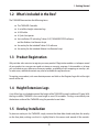
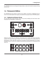
TWEAKER USER MANUAL
WWW.ELECTRIXPRO.COM
ELECTRIX TWEAKER User Manual
Table of Contents
1
Getting Started
1.1Introduction
1.2
What‘s Included in the Box?
1.3
Product Registration
1.4
Height Extension Legs
1.5
Overlay Installation
1.6
Firmware & Utilities
2Connections
2.1USB
2.2
MIDI In
2.3 MIDI Out 3
Hardware Controls
3.1Buttons
3.2Encoders
3.3 LED’s (Button Indicators)
3.4
LED Rings
3.5
Pressure Sensitive Pads 3.6Potentiometers
4
Default MIDI Settings
5
The Settings Channel
5.1
Encoder Settings
5.2
LED Ring Settings
6
SysEx Messages
6.1
System Exclusive Command Bytes
2
4
4
4
5
5
5
6
8
8
8
8
9
9
11
13
15
18
19
22
24
55
28
32
32
ELECTRIX TWEAKER User Manual
6.2
6.3
6.4
Set Messages
Request Responses
Message Glossary
32
39
40
Safety Instructions
liquid has been spilled or objects have fallen into the
apparatus, the apparatus has been exposed to rain
or moisture, does not operate normally, or has been
dropped.
Read these instructions. Keep these instructions.
Heed all warnings. Follow all instructions. Do not use
the apparatus near water. Clean only with dry cloth.
Use in accordance with the manufacturer’s
instructions. Do not use near any heat sources such
as radiators, heat registers, stoves, or other apparatus
(including amplifiers) that produce heat.
Please keep the unit in a well ventilated environment.
WARNING
To reduce the risk of fire or electric shock, do not
expose this apparatus to rain or moisture. The
apparatus shall not be exposed to dripping or
splashing and that no objects filled with liquids, such
as vases, shall be placed on the apparatus.
Protect the USB cord from being walked on or pinched
particularly at plugs, convenience receptacles, and
the point where they exit from the apparatus.
Only use attachments/ accessories specified by the
manufacturer.
CAUTION
To reduce the risk of electric shock, do not remove
any cover. No user-serviceable parts inside. Refer
servicing to qualified service personnel only.
Refer all servicing to qualified service personnel.
Servicing is required when the apparatus has been
damaged in any way, such as damaged connectors,
3
1. Getting Started
1 Getting Started
Thank you for purchasing the TWEAKER on behalf of the entire Electrix team. We hope you enjoy
performing with the TWEAKER as much as we enjoyed making it!
1.1Introduction
TWEAKER is a universal controller that offers lots of options for customization, but for those who
want to get started right away, we included mappings and overlays for popular programs like
Traktor and Ableton.
For those of you who like to dig a little deeper, the included TWEAKER EDITOR lets you customize
settings and save your own presets for use with a variety of software applications. This manual also
contains lots of useful information on default settings, SysEx used by TWEAKER, and the Settings
Channel, which is used to send MIDI messages back to TWEAKER to change settings on-the-fly.
4
1. Getting Started
1.2 What’s Included in the Box?
The TWEAKER box contains the following items:
The TWEAKER Controller
A set of four height-extension legs
A USB cable
A Quick Start poster
An installation CD including: Traktor 2 LE, TWEAKER EDITOR software,
and the Ableton Live Remote Script
8 An overlay for the included Traktor 2 LE software
8 An overlay for the included Ableton Live Remote Script
8
8
8
8
8
1.3 Product Registration
Why not take a few minutes to register your new product? Registration enables us to keep a record
of your product in case you ever need assistance or warranty coverage. It also enables us to keep
you up to date on any software or firmware updates, availability of new mappings or overlays, etc.
In some cases, additional content may also be available for registered users.
To register your product, visit www.electrixpro.com and click on the Register/Login link at the right
corner of the site.
1.4 Height Extension Legs
A set of four legs is included to extend the height of the TWEAKER to match traditional DJ gear. With
the legs installed, TWEAKER is the same height as most DJ turntables. The legs screw directly into
the bottom surface of the TWEAKER using the provided screw-holes.
1.5 Overlay Installation
To place an overlay on the TWEAKER, simply remove the three fader knobs and place the overlay
on the face plate, making sure that it is tightly fitted in the corners and around all the controls.
5
1. Getting Started
The TWEAKER enclosure was designed to keep overlays in place with minimal movement during
performances.
1.6 Firmware & Utilities
The TWEAKER’s firmware updates via USB. Firmware updates may become available from time to
time. Visit www.electrixpro.com to register your product and sign up to receive TWEAKER updates.
1.6.1 Checking Current Firmware Version
You can check your current firmware version at any time by holding the three buttons down
indicated on the image below, simultaneously:
While these three buttons are held down, the firmware version will be indicated on the bottom
encoder LED rings on both mixer channels. The left LED ring indicates the number before the
decimal point, and the right LED ring indicates the number after the decimal point. For example,
to indicate version 4.3, four LED’s will light up on the left ring, and three LED’s will light up on the
right ring.
6
1. Getting Started
1.6.2 Updating Firmware
1. Hold down the round rubber button located in the center of the four directional navigation
buttons, while connecting Tweaker to your computer,
2. A volume named TweakerDisk will mount on your system,
3. Drag the Tweaker firmware binary file and drop it onto the TweakerDisk volume,
4. The velocity pads will flash while the firmware is updating. Do not disconnect the USB cable
during this process,
5. It is safe to disconnect the USB once the pads have stopped flashing. Once the update is
complete you must reconnect the TWEAKER to return to normal operating mode.
1.6.3 LED Test
To test the LED’s, hold down button the large navigation encoder push button while connecting
Tweaker to your computer. All LED’s will light up. Press it again to exit and return to normal operating
mode.
7
2. Connections
2Connections
Any of the controls on TWEAKER can be configured to provide a wide range of functionality. Here
are some basic terms and uses for the controls.
2.1USB
The USB port connects to your computer to send and receive MIDI message, update the firmware,
and power the unit. This port is available to your software as Tweaker Port 1.
2.2 MIDI In
The MIDI Input port provides a standard 5 PIN MIDI jack to connect other MIDI devices to TWEAKER.
MIDI input data is then routed over USB to the host computer, and is available to your software on
the second port named “Tweaker Port 2.”
2.3 MIDI Out
The MIDI Output port provides a standard 5 PIN MIDI jack for outputting MIDI from your computer,
over the USB cable, and to the MIDI jack. TWEAKER will also send its data from the MIDI Out jack. This
MIDI Output can be accessed on your computer via the port named “Tweaker Port 2.”
8
3. Hardware Controls
3 Hardware Controls
Any of the controls on the TWEAKER can be configured to provide a wide range of functionality.
Here are some basic terms and uses for the controls.
3.1Buttons
The TWEAKER has 7 encoder push buttons and 43 custom-designed, soft-touch rubber buttons.
All button parameters can be controlled using the TWEAKER EDITOR software. The specific MIDI
messages that the TWEAKER recognizes are also detailed below.
Most music programs are designed to use momentary buttons. For this reason, the TWEAKER’s
buttons are momentary: they send a Note On message when pressed, and a Note Off message
when released. This is similar to the way piano keys operate.
9
3. Hardware Controls
3.1.2Mappability
Each button can be mapped to output Notes or CC’s. Each button may also function as a speed
control button for the encoders (detailed below). The assignment of each button may be modified
using the TWEAKER EDITOR or the ‘Set Button Mapping’ SysEx.
Note/ CC
Each button can be mapped to any note (0-127) and any CC (0-119). Multiple buttons can be
mapped to output to the same Note/ CC, but only one indicator LED can receive feedback on that
Note/CC. Each button has its own individual output channel.
The TWEAKER outputs a 127 ‘ON’ and 0 ‘OFF’ velocity when mapped as a Note or a CC.
Default Settings
Soft-touch buttons are mapped to Notes 1-43
Encoder push buttons are mapped to Notes 44-50
All buttons operate on MIDI Channel 1
Speed Control Button
The TWEAKER’s encoders are capable of increasing or decreasing their value at 2 assignable
encoder speeds. Any button may be mapped as a ‘Speed Control Button’ to toggle between these
two speeds. By default, the encoders increase values at about the same rate as a potentiometer,
and a little over a 3/4 turn achieves a full MIDI range of 0-127. This is encoder speed ‘5’. When you
switch to the default alternate speed for fine control with the speed control button, each click of
the encoder increments one value. At this speed, you need four full turns of the encoder to achieve
a full MIDI range of 0-127.
3.1.3 LED Feedback
All of the TWEAKER’s rubber buttons and pads are backlit by LED’s. Each LED can be controlled by
its respective button’s current state (on/off ). By default, Button Local Control of LED’s is disabled
because it can interfere with software MIDI feedback.
All button indicator LED’s can also be controlled by incoming MIDI Messages. By default, all button
indicator LED’s have the same mapping as their respective buttons. This makes TWEAKER compatible
with most music software that use MIDI feedback by default.
10
3. Hardware Controls
3.2Encoders
The TWEAKER has 7 encoders. Each encoder is capable of outputting in Absolute or Relative Mode.
The output mode of each encoder can be adjusted using the TWEAKER EDITOR, the Settings
Channel, or using the “Set Encoder Output Modes” SysEx.
3.2.1 Absolute Mode
When in Absolute Mode, an encoder outputs very much like an ordinary potentiometer. By default,
the six channel strip encoders are in Absolute Mode. Absolute mode is generally used to control
effects, EQ settings, and other continuous parameters. As you turn clock-wise, the encoder will
output increasing values until it outputs 127. As you turn counter clock-wise, the encoder will
output decreasing values until it outputs 0. If Local Control of the LED rings in is enabled, the ring
will update the display the current value of the encoder.
Local Control for encoders in Absolute Mode can be controlled using the TWEAKER EDITOR or the
Ring Local Control feature of the Settings Channel.
Encoder Speeds
The angle of turn needed to complete a full 0-127 sweep on an encoder is dependent on the
declared encoder speed. This is a global control. The default speed is 5, and the default alternate
speed is 1. At a Speed of 5, the Encoder changes value at about the same rate as a potentiometer.
At a Speed of 1, the encoder’s natural speed, an encoder changes value at 1 value per encoder
click/detent (about one quarter of the rate of a potentiometer). Maximum Encoder Speed is 7, and
Minimum Speed is 1. The TWEAKER stores 2 encoder speeds at a time, and they can be toggled
between using a Speed Control Button.
11
3. Hardware Controls
Encoder speeds are assignable by the TWEAKER EDITOR’s “encspeedA” and “encspeedB” functions,
by sending a message to an encoder on the Settings Channel, or using the “Set Encoder Speeds”
SysEx Message.
MIDI Feedback
Encoders in Absolute Mode accept standard MIDI Feedback. If the TWEAKER receives a message
with the same mapping as an encoder, it will use the value of that message to set the current value
of the encoder.
For example, If the message “CC57, value 127, on Channel 1” is received by a TWEAKER with default
settings, it will update its stored value for the top-left encoder to 127. If Ring Local Control is enabled,
the LED Ring will update the display the current value of the encoder.
MIDI Feedback Loops
In order to eliminate feedback loops that could lock an encoder at a value, the TWEAKER will
ignore a MIDI message that is mapped to an encoder that is actively being turned by the user. This
is especially helpful for TRAKTOR’s feedback system, which will send a message right back to the
TWEAKER after receiving it in some cases. The TWEAKER can still accept messages that are mapped
to the LED Ring that accompanies that encoder during this period if Ring Local Control for encoders
in Absolute Mode is disabled.
3.2.2Relative
The TWEAKER’s encoders can also operate in Relative Mode. This version of relative mode is known
as “2’s Compliment.” When in Relative Mode, an encoder outputs continuously in either direction.
Relative Mode is generally used to cycle through long lists, adjust track position, and other
incremental adjustments that require more than the traditional 0-127 output. By default, the large
navigation encoder is in Relative Mode.
The TWEAKER only outputs two messages in Relative Mode:
8 Clockwise: +1 ( velocity/ value 1 )
8 Counter-Clockwise: -1 ( velocity/ value 127 )
One message is output for each click of the encoder (increment or decrement). There are
approximately 30 increments in one full rotation of an encoder. If Ring Local Control in Relative
Mode is enabled, the LED Ring will update to show the direction of the encoder’s last turn.
Ring Local Control in Relative Mode can be controlled using the Local Control feature of the Settings
Channel.
12
3. Hardware Controls
MIDI Feedback
Encoders in Relative Mode are capable of accepting MIDI feedback to the LED Rings. If the TWEAKER
receives a message with the same mapping as an LED Ring, the TWEAKER will use that message to
set the current display of the LED Ring based on the LED Ring’s Display Mode and the value of the
message.
If Ring Local Control in Relative Mode is disabled, software applications capable of sending scaled
feedback to one of these LED rings can display absolute-style feedback to your TWEAKER for
controls that you are modifying with an encoder in Relative Mode.
3.2.3Mappability
Note/ CC Messages
Each encoder can be mapped to output to any CC (0-119) using the TWEAKER EDITOR or the “Set
Encoder Mappings” SysEx. Multiple encoders can be mapped to output to the same Note/ CC, but
only one will be able to receive direct feedback via MIDI message in this case. Each encoder has it’s
own individual output channel that can be changed using the TWEAKER EDITOR.
3.3 LED’s (Button Indicators)
The TWEAKER has a total of 57 button indicator LED’s: 38 RGB LED’s, 13 red monochrome LED’s, and
6 blue monochrome LED’s for the encoder push buttons.
3.3.1 Reception Modes
The LED’s are capable of responding to Note / CC MIDI messages as well as button presses.
Note/ CC
LED mappings follow the mapping of the corresponding buttons or pads. By remapping the
matched button or pad, each LED can be mapped to respond to any Note (0-127) and any CC (0115) using the TWEAKER EDITOR or the “Map Buttons” SysEx Messages.
Each RGB LED has it’s own individual reception channel and mapping, which is independent of
the button mapping. Each monochrome LED shares its individual reception channel with the
corresponding button.
13
3. Hardware Controls
Default Settings
8
8
8
8
8
The RGB LED’s are mapped to Notes 1-38
The Red LED’s used for the navigation style buttons are mapped to Notes 39-43.
The Red LED’s used for pressure sensitive pads are mapped to Notes 63-70.
The Blue LED’s to indicate encoder push button activity are mapped to Notes 45-50.
All LED’s are mapped to MIDI Channel 1
Button Local Control
These Button Indicator LED’s can also be locally controlled. In other words, they can light in reaction
to a Button’s Current State, but only if the Button Local Control is enabled for the Button.
Button Local Control can be turned on and off in the TWEAKER EDITOR’s Global Settings, or by CC
Message using the ‘Local Control’ feature of the Settings Channel (See Chapter 6 for details).
14
3. Hardware Controls
3.3.2 Display Styles
RGB LED’s
There are 38 RGB (Red/Green/Blue) LED’s: 32 for the grid and three per channel strip. They have
eight states:
8 000-000: Off
8 001-003: Green
8 004-007: Red
8 008-015: Yellow
8 016-031: Blue
8 032-063: Cyan
8 064-126: Magenta
8 127-127: White
Monochromatic LED’s
There are 13 red monochrome LED’s and 6 blue monochrome LED’s. They have two states:
8 000-063: LED Turns Off
8 064-127: LED Turns Solid On
3.4 LED Rings
There are three LED rings per mixer channel strip. Each LED Ring is composed of 13 red LED’s.
3.4.1 Reception Modes
An LED ring’s display can be controlled by incoming Note / CC MIDI messages and the by the
encoder it surrounds.
By default, encoders are in Absolute Mode, and the LED rings display the current value of the
encoder. An LED ring also updates when the TWEAKER receives a MIDI message that matches its
mapping.
Note/ CC Messages
LED Ring mappings can be modified using the TWEAKER EDITOR, or the “Set LED Ring Map” SysEx
message. When the TWEAKER receives an LED ring-directed message, the LED ring is updated as
determined by its display mode and message velocity/value. These messages do not affect the
15
3. Hardware Controls
encoder value.
Default Settings
The LED Rings are mapped to CC79-84 on MIDI Channel 1.
Encoder Local Control
By default, the LED rings are locally controlled by the encoders. Locally controlled encoders can
update the LED rings when:
8 User turns the encoder, or
8 TWEAKER receives a MIDI message (also known as a feedback message) that matches the
mapping of the encoder.
3.4.2 Display Modes
The LED rings have four modes to accurately display the current state of any function. The display
mode of each LED ring can be set using the TWEAKER EDITOR, by using the “Set LED Display Mode”
SysEx, or by basic Note / CC Messages, using the LED rings feature of the Settings Channel.
Walk
Walk mode lights 1 LED at a time and seemingly walks up as encoder’s value increases. This mode
has 14 states, so the visual resolution of each state is about 9 MIDI values.
Fill
Fill mode lights all preceding LED’s as encoder’s value increases. This Mode has 14 States, so the
visual resolution of each state is about 9 MIDI values.
16
3. Hardware Controls
EQ
EQ mode lights from the center LED and stretches either to the left or right depending on the LED
ring’s display value. When the LED ring’s display value reaches 0, the LED’s on the left side will all be
lit. When the LED ring’s display value reaches 127, the LED’s on the right side will all be lit. This mode
has 13 states, so the visual resolution of each state is about 10 MIDI Values. This mode is good for
parameters that are centered around MIDI value 63-64, such as EQ and pan.
By default, the LED rings are in EQ mode.
Spread
Spread mode lights the rings from the center LED out to both edges. This Mode has 8 states, so the
visual resolution of each state is about 15 MIDI Values. This display mode is especially effective for
resonance (width) controls of parametric EQ’s.
Relative
Relative Mode is used only for relative encoder local control, and cannot be specially assigned.
It has five states; still, incrementing, incrementing (alternate), decrementing, and decrementing
(alternate).
Dual Display
LED rings are capable of responding to incoming MIDI messages, and being controlled by encoder
movements at the same time. You may, for example, have your software stream the current track’s
output level on CC79 (the top-left LED Ring). You may also have that encoder at CC57 controlling the
fader volume for the track. In this example, when you turn the encoder, the LED ring will temporarily
allow the encoder value to display on the LED ring. When you finish turning, the TWEAKER will
release the control of the LED ring back to the MIDI stream of the current track’s level.
17
3. Hardware Controls
3.5 Pressure Sensitive Pads
The TWEAKER has 8 large pressure sensitive pads for drumming or expressive control of effects.
3.5.1 Modes of Output
Each pad is capable of outputting in Note messages upon press and release (like a keyboard), to
trigger drums or play melodies. Each pad can also stream CC messages of the current value while
the pad is depressed, so you can use your favorite software modulate LFO’s or perform bends on
the notes after trigger.
The output modes and the Note and CC mappings of each pad can be adjusted using the TWEAKER
EDITOR or the “Pressure Sensitive Pad Settings” SysEx.
3.5.2 Pad Trigger and Return Values
The Pressure at which a Pad Generates a Note On message (and starts streaming CC messages)
is customizable. Similarly the pressure at which a pad generates a Note Off message (and stops
streaming CC messages) is also customizable using the Trigger and Return features of TWEAKER
EDITOR or the “FSR Settings” SysEx message
3.5.3 Pad Sensitivity
The amount of pressure required to reach the maximum velocity (127) is also customizable. At
the maximum sensitivity of 5, maximum value is easily achieved and value increases quickly with
increasing pressure. Whereas at a sensitivity of 0, value increases slowly with increasing pressure.
The default sensitivity is 4. Pad sensitivity can be adjusted using the TWEAKER EDITOR or the “Force
Sensitive Pad Settings” SysEx message.
18
3. Hardware Controls
3.5.4 Pad CC Retrigger Rate
The pads are capable of outputting CC’s at a predefined rate in multiples of 5 milliseconds (ms).
By default, this rate is 45ms. It can be modified using the TWEAKER EDITOR or the “Force Sensitive
Pad Settings” SysEx message.
3.5.5Mappability
Each pad can output Notes and CC’s. The Note mapping acts like a normal keyboard key, with a Note
On message of a velocity proportional to the force of the hit when the pad is struck. The TWEAKER
outputs a Note Off message when the pad is released. The CC output reacts like a potentiometer.
While a pad is depressed, the TWEAKER will stream with a value proportional to the force at which
the pad is pressed.
The assignment of each Note and CC mapping may be modified using the TWEAKER EDITOR or
the “Set Button Mapping” SysEx. The CC Output may be disabled using TWEAKER EDITOR or the
“Pressure Sensitive Pad Settings” SysEx.
Note/ CC
Each button can be mapped as any Note (0-127) and any CC (0-119). Multiple pads can be mapped
to output to the same Note/ CC, but only one LED can receive feedback on that Note/CC. Each pad
has it’s own individual output channel.
Default Settings
The pads are mapped to Notes 63-70 and CC’s 71-78.
The indicator LED for each pad is controlled by the pad’s Note mapping.
All pads are mapped to MIDI Channel 1.
3.6Potentiometers
The TWEAKER has a total of five potentiometers: two rotary pots, two vertical sliders, and a crossfader.
All pots operate in Absolute Mode, which is useful for controlling volume, gain, or other continuous
parameters. As you turn clockwise (or slide upward), the pot will output increasing values until it
outputs 127. As you turn counter clockwise (or slide downward), the pot will output decreasing
values until it outputs 0.
Center Note Messages
The rotary and vertical sliders have a center detent, which are capable of outputting MIDI Note
messages. The TWEAKER outputs the following Note messages by default:
19
3. Hardware Controls
8 Potentiometer reaches center: TWEAKER sends note off (velocity 0)
8 Potentiometer leaves center (increasing) TWEAKER sends note on velocity 127
8 Potentiometer leaves center (decreasing): TWEAKER sends note on velocity 64
These messages were designed so that a tweaker’s potentiometer can naturally turn off filters and
effects when it reaches center value, or have a different effect or function assigned to each half of
the pot.
20
3. Hardware Controls
3.6.1Mappability
CC Messages
Each potentiometer can be mapped to output to any CC (0-119) using the TWEAKER EDITOR or the
“Set Potentiometer Mappings” SysEx. Multiple pots can be mapped to output to the same CC. Each
encoder has it’s own individual output channel that can be changed using the TWEAKER EDITOR.
Center Note Messages
Each potentiometer’s center note message is mapped to the same note as it’s cc mapping. For
example, by default the left channel strip slider outputs channel 1, CC 53. Similarly, the center note
message for that slider outputs channel 1, note 53.
Default Settings
Rotary potentiometers are mapped to CC/Notes 51-52
Vertical sliders are mapped to CC/Notes 53-54
Crossfader is mapped to CC 55
All pots are mapped to MIDI Channel 1
21
4. Default MIDI Settings
4 Default MIDI Settings
The following is a list of the TWEAKER’s factory default MIDI note and CC settings.
Soft Touch Buttons
Force Sensitive Pads
Mapping: MIDI Notes 1-38
MIDI Channel: 1
No Speed Control Buttons Enabled
Mapping: MIDI Notes 63-70
Mapping: MIDI CC’s 71-78
MIDI Channel: 1
No Speed Control Buttons Enabled
q RGB LED’s
Mapping: MIDI Notes 1-38
MIDI Channel: 1
Auto-light (Local Control): Off
q Red LED’s (Force Sensitive Pad Indicators)
Mapping: MIDI Notes 63-70
MIDI Channel: 1
Auto-light (Local Control): Off
Soft Touch Navigation Buttons
Rotary Encoders
Mapping: MIDI Notes 39-43
MIDI Channel: 1
No Speed Control Buttons Enabled
Mapping: MIDI CC’s 56-62
MIDI Channel: 1
Encoder Speed1: 5
Encoder Speed2: 1
Output Mode: Absolute Mode (except
Navigation Encoder which is in Relative Mode)
q Red LED’s (Navigation Button Indicators)
Mapping: MIDI Notes 39-43
MIDI Channel: 1
Auto-light (Local Control): Off
q LED Rings
Mapping: MIDI CC’s 79-84
MIDI Channel: 1
Encoder Link: On
Ring Mode: EQ Mode
Encoder Push Buttons
Mapping: MIDI Notes 44-50
MIDI Channel: 1
No Speed Control Buttons Enabled
q Blue LED’s (Encoder Push Button Indicators)
Mapping: MIDI Notes 44-50
MIDI Channel: 1
Auto-light (Local Control): Off
General MIDI
Local Control: Off
Omni Channel: Off
External MIDI Jacks: Enabled
Potentiometers (Includes Faders)
Mapping (normal output): MIDI CC’s 51-55
Mapping (Center-Note): MIDI Notes 51-54
MIDI Channel: 1
22
4. Default MIDI Settings
D#1
BUTTON: A1
ENCODER: CC 57
RING: CC 79
BUTTON: G#1
ENCODER: CC 56
F#1
E1
POT:
BUTTON: C2
ENCODER: CC 60
RING: CC82
G1
POT:
F1
CC 51
CC 52
CENTER NOTE:
CENTER NOTE:
D#2
BUTTON: A#1
ENCODER: CC 58
RING: CC80
E2
NOTE:
NOTE:
NOTE:
NOTE:
AFTERTOUCH:
AFTERTOUCH:
AFTERTOUCH:
AFTERTOUCH:
D#3
E3
CC 71
BUTTON: B1
ENCODER: CC 59
RING: CC81
CC 72
F#3
CC 73
CC 74
BUTTON: D2
ENCODER: CC 62
RING: CC 84
NOTE:
NOTE:
NOTE:
NOTE:
AFTERTOUCH:
AFTERTOUCH:
AFTERTOUCH:
AFTERTOUCH:
G3
A0
F3
G#3
CC 75
A3
CC 76
A#3
CC 77
CC 78
A#0
C#-2
D-2
D#-2
E-2
F-2
F#-2
G-2
G#-2
A-2
A#-2
B-2
C-1
C#-1
D-1
D#-1
E-1
F-1
F#-1
G-1
G#-1
A-1
A#-1
B-1
C0
POT:
CC 53
F2
C1
C#1
POT:
CENTER NOTE:
BUTTON: C#2
ENCODER: CC 61
RING: CC 83
CC 54
C#0
D0
D#0
F0
E0
F#0
G0
G#0
B0
CENTER NOTE:
F#2
D1
CC 55
TWEAKER DEFAULT MIDI MAP
(Blank maps are available online in pdf format)
23
5. The Settings Channel
5 The Settings Channel
The settings channel is reserved for the use of standard MIDI CC messages to configure different
TWEAKER settings. Send a CC number on this channel to the TWEAKER and, if it matches the CC
number mapping for an LED ring or an encoder, the value will change its properties.
The following properties can be modified using the settings channel:
8 Encoder speed
8 Encoder mode (absolute/relative)
8 LED rings display style
8 Local Control (CC# 122)
The tables below describe each bit in the 7-bit value of the MIDI CC message for the Encoders, LED
Rings, and Local Control. It is these combinations of bits that determine the final value of the CC
message.
Encoders
Position Name
MSB
LSB
Position
7
6
5
4
3
2
1
0
Descriptor
xMIDIx
SB
EOM1
EOM0
ES3
ES2
ES1
ES0
Value
0
1
1
1
1
1
0
0
LED Rings
Position Name
MSB
LSB
Position
7
6
5
4
3
2
1
0
Descriptor
xMIDIx
SB
ALD
ELD
RM3
RM2
RM1
RM0
Value
0
1
1
1
1
1
0
0
Local Control
Local Control
Position Name
MSB
Position
7
6
5
4
3
2
1
LSB
0
Descriptor
xMIDIx
SB
BTN
BTNT
ENCA
ENCR
ANA
x
Value
0
0
0
0
0
0
0
0
24
5. The Settings Channel
4RM = Ring Mode
4SB = Security Bit (0 = ignore message, 1=accept message)
4ES = Encoder Speed
4EOM0 = Encoder Output Mode (0=absolute,1=relative
4EOM1 <reserved>
4ENCR = Encoder Relative Local Control
4ENCA = Encoder Absolute Local Control
4ANA = Analog Local Control
5.1 Encoder Settings
5.1.1 Default Settings
Settings Channel:
16
Encoder Mappings:
Min: CC56
Max: CC62
5.1.2 Encoder Response Table
Value
Received by
Tweaker
Expected Change to Encoder Properties
Ring Mode
Encoder
Output Mode
Encoder Speed
(global)
0-63
<nc>
<nc>
<nc>
64
Fill
Relative
<nc>
65
Walk
Relative
<nc>
66
EQ
Relative
<nc>
67
Spread
Relative
<nc>
68
Fill
Absolute
<nc>
69
Walk
Absolute
<nc>
70
EQ
Absolute
<nc>
71
Spread
Absolute
<nc>
72
Fill
Relative
1
25
5. The Settings Channel
73
Walk
Relative
1
74
EQ
Relative
1
75
Spread
Relative
1
76
Fill
Absolute
1
77
Walk
Absolute
1
78
EQ
Absolute
1
79
Spread
Absolute
1
80
Fill
Relative
2
81
Walk
Relative
2
82
EQ
Relative
2
83
Spread
Relative
2
84
Fill
Absolute
2
85
Walk
Absolute
2
86
EQ
Absolute
2
87
Spread
Absolute
2
88
Fill
Relative
3
89
Walk
Relative
3
90
EQ
Relative
3
91
Spread
Relative
3
92
Fill
Absolute
3
93
Walk
Absolute
3
94
EQ
Absolute
3
95
Spread
Absolute
3
96
Fill
Relative
4
97
Walk
Relative
4
98
EQ
Relative
4
99
Spread
Relative
4
100
Fill
Absolute
4
101
Walk
Absolute
4
102
EQ
Absolute
4
103
Spread
Absolute
4
26
5. The Settings Channel
104
Fill
Relative
5
105
Walk
Relative
5
106
EQ
Relative
5
107
Spread
Relative
5
108
Fill
Absolute
5
109
Walk
Absolute
5
110
EQ
Absolute
5
111
Spread
Absolute
5
112
Fill
Relative
6
113
Walk
Relative
6
114
EQ
Relative
6
115
Spread
Relative
6
116
Fill
Absolute
6
117
Walk
Absolute
6
118
EQ
Absolute
6
119
Spread
Absolute
6
120
Fill
Relative
7
121
Walk
Relative
7
122
EQ
Relative
7
123
Spread
Relative
7
124
Fill
Absolute
7
125
Walk
Absolute
7
126
EQ
Absolute
7
127
Spread
Absolute
7
Sample Messages
CC 56, Channel 16, Velocity 64
Puts the large navigation encoder in Relative Mode
CC 56, Channel 16, Velocity 63
No change to the large navigation encoder
27
5. The Settings Channel
CC 57, Channel 16, Velocity 68
Puts the top-left encoder in Absolute Mode
Puts the top-left encoder’s LED ring in Fill Mode
No change to encoder speed
CC 57, Channel 16, Velocity 69
Puts the top-left encoder in Absolute Mode
Puts the top-left encoder’s LED ring in Walk Mode
No change to encoder speed
CC 57, Channel 16, Velocity 70
Puts the top-left encoder in Absolute Mode
Puts the top-left encoder’s LED ring in EQ Mode
No change to encoder speed
CC 57, Channel 16, Velocity 71
Puts the top-left encoder in Absolute Mode
Puts the top-left encoder’s LED ring in Spread Mode
No change to encoder speed
5.2 LED Ring Settings
5.2.1 Default Settings
Default Settings Channel:
16
Default LED Ring Mappings:
Min: CC79
Max: CC84
28
5. The Settings Channel
5.2.2 LED Rings Response Table
Value Received
by Tweaker
Expected Change to Encoder Properties
Ring Mode
Encoder
Output Mode
Encoder Speed
(global)
Encoder Local
Control of LED
Rings
0-63
<nc>
<nc>
<nc>
<nc>
64
Fill
<nc>
<nc>
enabled
65
Walk
<nc>
<nc>
enabled
66
EQ
<nc>
<nc>
enabled
67
Spread
<nc>
<nc>
enabled
68
Fill
<nc>
<nc>
enabled
69
Walk
<nc>
<nc>
enabled
70
EQ
<nc>
<nc>
enabled
71
Spread
<nc>
<nc>
enabled
72
Fill
<nc>
<nc>
enabled
73
Walk
<nc>
<nc>
enabled
74
EQ
<nc>
<nc>
enabled
75
Spread
<nc>
<nc>
enabled
76
Fill
<nc>
<nc>
enabled
77
Walk
<nc>
<nc>
enabled
78
EQ
<nc>
<nc>
enabled
79
Spread
<nc>
<nc>
enabled
80
Fill
<nc>
<nc>
enabled
81
Walk
<nc>
<nc>
enabled
82
EQ
<nc>
<nc>
enabled
83
Spread
<nc>
<nc>
enabled
84
Fill
<nc>
<nc>
enabled
85
Walk
<nc>
<nc>
enabled
86
EQ
<nc>
<nc>
enabled
87
Spread
<nc>
<nc>
enabled
88
Fill
<nc>
<nc>
enabled
29
5. The Settings Channel
89
Walk
<nc>
<nc>
enabled
90
EQ
<nc>
<nc>
enabled
91
Spread
<nc>
<nc>
enabled
92
Fill
<nc>
<nc>
enabled
93
Walk
<nc>
<nc>
enabled
94
EQ
<nc>
<nc>
enabled
95
Spread
<nc>
<nc>
enabled
96
Fill
<nc>
<nc>
disabled
97
Walk
<nc>
<nc>
disabled
98
EQ
<nc>
<nc>
disabled
99
Spread
<nc>
<nc>
disabled
100
Fill
<nc>
<nc>
disabled
101
Walk
<nc>
<nc>
disabled
102
EQ
<nc>
<nc>
disabled
103
Spread
<nc>
<nc>
disabled
104
Fill
<nc>
<nc>
disabled
105
Walk
<nc>
<nc>
disabled
106
EQ
<nc>
<nc>
disabled
107
Spread
<nc>
<nc>
disabled
108
Fill
<nc>
<nc>
disabled
109
Walk
<nc>
<nc>
disabled
110
EQ
<nc>
<nc>
disabled
111
Spread
<nc>
<nc>
disabled
112
Fill
<nc>
<nc>
disabled
113
Walk
<nc>
<nc>
disabled
114
EQ
<nc>
<nc>
disabled
115
Spread
<nc>
<nc>
disabled
116
Fill
<nc>
<nc>
disabled
117
Walk
<nc>
<nc>
disabled
118
EQ
<nc>
<nc>
disabled
119
Spread
<nc>
<nc>
disabled
30
5. The Settings Channel
120
Fill
<nc>
<nc>
disabled
121
Walk
<nc>
<nc>
disabled
122
EQ
<nc>
<nc>
disabled
123
Spread
<nc>
<nc>
disabled
124
Fill
<nc>
<nc>
disabled
125
Walk
<nc>
<nc>
disabled
126
EQ
<nc>
<nc>
disabled
127
Spread
<nc>
<nc>
disabled
Sample Messages
CC 79, Channel 16, Velocity 68
No change to encoder output mode
Puts the top-left encoder’s LED ring in Fill Mode
No change to encoder speed
Ring Local Control is ‘enabled’ and encoders can control LED rings
(This modifies same variable as sysex 11 ‘Disable Encoder Local Control’)
CC 79, Channel 16, Velocity 100
No change to encoder output mode
Puts the top-left encoder’s LED ring in Fill Mode
No change to encoder speed
Ring Local Control is ‘disabled’ and encoders cannot control LED rings
(This modifies same variable as sysex 14 ‘Disable Encoder Local Control’)
31
6. SysEx Messages
6 SysEx Messages
The following is a list of the TWEAKER’s factory default MIDI note and CC settings.
6.1 System Exclusive Command Bytes
The System Exclusive message includes the official MIDI Manufacturer ID for ELECTRIX, a Product
number, and the Command number. Each command is described in the following sections.
240, 0, 1, 106, 1, NN, ..., 247
The ELECTRIX identification number is 6A
The TWEAKER product number is 01
The Command number is NN
Note: All numbers in this specification are Base-10 (Decimal) numbers unless otherwise noted.
6.2 Set Messages
These messages allow you to change the settings of the TWEAKER.
01 : Button Mappings
This Message changes the MIDI mapping (Channel, Note/CC, and Number).
Total Bytes: Data Bytes: Data Bytes per Button: 1st Data Byte Received: 2nd Data Byte Received: 107
100
2
Mapping Number
Channel Number/ Output Type
Special Cases:
Encoder Speed Control Button
Output Type = 1
Mapping Number = 127
32
6. SysEx Messages
Message for Default Settings:
< 240, 00, 01, 106, 01, 01, 00, 01, 00, 02, 00, 03, 00, 04, 00, 05, 00, 06, 00, 07, 00, 08, 00, 09, 00, 10, 00,
11, 00, 12, 00, 13, 00, 14, 00, 15, 00, 16, 00, 17, 00, 18, 00, 19, 00, 20, 00, 21, 00, 22, 00, 23, 00, 24, 00,
25, 00, 26, 00, 27, 00, 28, 00, 29, 00, 30, 00, 31, 00, 32, 00, 33, 00, 34, 00, 35, 00, 36, 00, 37, 00, 38, 00,
39, 00, 40, 00, 41, 00, 42, 00, 43, 00, 44, 00, 45, 00, 46, 00, 47, 00, 48, 00, 49, 00, 50, 247 >
02 : Potentiometer Mappings
This message changes the MIDI mapping of all potentiometers (Channel, Note/CC, and Number).
Total Bytes:
19
Data Bytes:
12
Data Bytes per Pot:
2
1st Data Byte Received:
Mapping Number
2nd Data Byte Received:
Channel Number/ Output Type
Message for Default Settings:
< 240, 00, 01, 106, 01, 02, 00, 51, 00, 52, 00, 53, 00, 54, 00, 55, 247 >
03 : Encoder Mappings
This message changes the MIDI mapping of all encoders (Channel, CC Only, and Number).
Total Bytes:
21
Data Bytes:
14
Data Bytes per Encoder:
2
1st Data Byte Received:
Mapping Number
2nd Data Byte Received:
Channel Number/ Output Type
33
6. SysEx Messages
Message for Default Settings:
< 240, 00, 01, 106, 01, 03, 00, 56, 00, 57, 00, 58, 00, 59, 00, 60, 00, 61, 00, 62, 247 >
04 : Force Sensitive Pad Mappings
This message changes the MIDI mapping of all 8 force sensitive pads (Channel, Notes (CC’s), and
Number).
Total Bytes:
21
Data Bytes:
14
Data Bytes per Pad:
4 (2 sets of 2)
1st Data Byte Received:
Mapping Number
2nd Data Byte Received:
Channel Number/ Output Type
Special Cases:
In this message, the first 16 data bytes designate the Note On/ Note Off mappings for the pads. The
second 16 data bytes designate the CC (Retriggering) mappings.
Message for Default Settings:
< 240, 00, 01, 106, 01, 04, 00, 63, 00, 64, 00, 65, 00, 66, 00, 67, 00, 68, 00, 69, 00, 70, 00, 71, 00, 72, 00,
73, 00, 74, 00, 75, 00, 76, 00, 77, 00, 78, 247 >
05 : Encoder Settings
This Message changes all of the settings for all encoders.
1st Data Byte Received:
Encoders Absolute/ Relative
2nd Data Byte Received:
Encoder Speed A
3rd Data Byte Received:
Encoder Speed B
Total Bytes:
10
34
6. SysEx Messages
Data Bytes:
3
Data Bytes per Encoder :
Not Applicable
Message for Default Settings:
< 240, 0, 1, 106, 01, 05, 126, 05, 01, 247 >
06 : FSR Settings
This message changes all settings for all pads.
1st Data Byte Received:
CC Retrigger On (Force Sensitive Pads 1-7)
2nd Data Byte Received:
CC Retrigger On (Force Sensitive Pad 8)
3rd Data Byte Received:
Note On Pressure Threshold (Low)
4th Data Byte Received:
Note On Pressure Threshold (High)
5th Data Byte Received:
Note Off Pressure Threshold (Low)
6th Data Byte Received:
Note Off Pressure Threshold (High)
7th Data Byte Received:
CC Resend Rate
8th Data Byte Received:
Force Sensitive Pad Sensitivity
Total Bytes:
10
Data Bytes:
3
Data Bytes per Pad:
Not Applicable
Message for Default Settings:
< 240, 00, 01, 106, 01, 06, 127, 127, 15, 00, 07, 00, 09, 5, 247 >
35
6. SysEx Messages
07 : LED Ring Output Modes
This Message changes the display mode of all LED rings (Walk, Fill, Spread, or EQ).
Total Bytes:
9
Data Bytes:
2
LED Rings per Data Byte:
3
Bits per LED Ring:
2
1st Data Byte Received:
LED Rings 1-3
(Bitwise: x 0 r3h r3l | r2h r2l r1h r1l )
2nd Data Byte Received:
LED Rings 4-6
(Bitwise: x 0 r4h r4l | r5h r5l r6h r6l )
Valid Output Modes:
0: Fill
1: Walk
2: EQ
3: Spread
Message for Default Settings (All EQ Mode):
< 240, 0, 1, 106, 01, 07, 42, 42, 247 >
08 : Map RGB LED’s
This Message changes the MIDI mapping of all RGB LED’s (Channel, CC Only, and Number).
Total Bytes:
83
Data Bytes:
76
Data Bytes per RGB LED:
2
1st Data Byte Received:
Mapping Number
2nd Data Byte Received:
Channel Number/ Output Type
Message for Default Settings:
< 240, 00, 01, 106, 01, 08, 0, 1, 0, 2, 0, 3, 0, 4, 0, 5, 0, 6, 0, 7, 0, 8, 0, 9, 0, 10, 0, 11, 0, 12, 0, 13, 0, 14, 0, 15,
0, 16, 0, 17, 0, 18, 0, 19, 0, 20, 0, 21, 0, 22, 0, 23, 0, 24, 0, 25, 0, 26, 0, 27, 0, 28, 0, 29, 0, 30, 0, 31, 0, 32, 0,
33, 0, 34, 0, 35, 0, 36, 0, 37, 0, 38, 247 >
36
6. SysEx Messages
09 : Map LED Rings
This message changes the MIDI mapping of all LED rings (Channel, CC Only, and Number).
Total Bytes:
19
Data Bytes:
12
Data Bytes per LED Ring:
2
1st Data Byte Received:
Mapping Number
2nd Data Byte Received:
Channel Number/ Output Type
Message for Default Settings:
< 240, 00, 01, 106, 01, 09, 0, 79, 0, 80, 0, 81, 0, 82, 0, 83, 0, 84, 247 >
13 : Set Settings Channel
This Message changes the Settings Channel.
Total Bytes:
8
Data Bytes:
1
1st Data Byte Received:
MIDI Channel
0 = MIDI Channel 1
15 = MIDI Channel 16
Message for Default Settings Channel (MIDI Channel 16):
< 240, 0, 1, 106, 01, 13, 15, 247 >
37
6. SysEx Messages
14 : Disable Encoder Local Control
This message can enable or disable Ring Local Control for the encoders.
Total Bytes:
8
Data Bytes:
1
1st Data Byte Received:
Local Control Disabled?
0 = Enabled
1+ = Disabled
Message for Default Settings (Enabled):
< 240, 0, 1, 106, 01, 14, 0, 247 >
15 : Disable Potentiometer Center Note Messages
This message can enable or disable the Note On and Off messages that are sent by the potentiometer
when the control enters and leaves the center detent.
Total Bytes:
8
Data Bytes:
1
1st
Data
Received:
Byte Local Control Disabled?
0 = Enabled
1+ = Disabled
Message for Default Settings (Enabled):
< 240, 0, 1, 106, 01, 15, 0, 247 >
126 : Request Controller Configuration
This Message asks the TWEAKER to send a return message detailing all of its settings.
Total Bytes:
8
Data Bytes:
0
Message to Request Settings:
< 240, 0, 1, 106, 01, 126, 247 >
38
6. SysEx Messages
127 : Save Maps and Settings
The TWEAKER saves all of its current settings as the default settings when it receives this message.
User settings will be stored in flash memory and automatically restored whenever it is powered up.
Message to Save Settings:
< 240, 0, 1, 106, 01, 127, 247 >
6.3 Request Responses
125 : Acknowledgement
The TWEAKER sends this message any time it receives a valid SysEx message.
Total Bytes:
7
Data Bytes:
0
Response:
< 240, 0, 1, 106, 01, 125, 247 >
39
6. SysEx Messages
126 : Receive Controller Configuration
The TWEAKER sends this message in response to a Request Controller Configuration Message.
Total Bytes:
108
Data Bytes:
101
Default Settings Response:
< 240, 0, 1, 106, 1, 126,
Button Map: 0, 1, 0, 2, 0, 3, 0, 4, 0, 5, 0, 6, 0, 7, 0, 8, 0, 9, 0, 10, 0, 11, 0, 12, 0, 13, 0, 14, 0, 15, 0, 16, 0, 17,
0, 18, 0, 19, 0, 20, 0, 21, 0, 22, 0, 23, 0, 24, 0, 25, 0, 26, 0, 27, 0, 28, 0, 29, 0, 30, 0, 31, 0, 32, 0, 33, 0, 34, 0,
35, 0, 36, 0, 37, 0, 38, 0, 39, 0, 40, 0, 41, 0, 42, 0, 43, 0, 44, 0, 45, 0, 46, 0, 47, 0, 48, 0, 49, 0, 50,
Pot/Fader Map: 0, 51, 0, 52, 0, 53, 0, 54, 0, 55,
Encoder Map: 0, 56, 0, 57, 0, 58, 0, 59, 0, 60, 0, 61, 0, 62,
FSR Map CCs: 0, 63, 0, 64, 0, 65, 0, 66, 0, 67, 0, 68, 0, 69, 0, 70,
FSR Map Notes: 0, 71, 0, 72, 0, 73, 0, 74, 0, 75, 0, 76, 0, 77, 0, 78,
Encoder Settings: 126, 5, 1,
FSR Settings: 1, 127, 15, 0, 7, 0, 9, 4,
Local Control Flags: 4,
Settings Channel: 15,
LED Ring Mode: 42, 42,
LED Map: 0, 1, 0, 2, 0, 3, 0, 4, 0, 5, 0, 6, 0, 7, 0, 8, 0, 9, 0, 10, 0, 11, 0, 12, 0, 13, 0, 14, 0, 15, 0, 16, 0, 17, 0,
18, 0, 19, 0, 20, 0, 21, 0, 22, 0, 23, 0, 24, 0, 25, 0, 26, 0, 27, 0, 28, 0, 29, 0, 30, 0, 31, 0, 32, 0, 33, 0, 34, 0,
35, 0, 36, 0, 37, 0, 38,
LED Ring Map: 0, 79, 0, 80, 0, 81, 0, 82, 0, 83, 0, 84, 247 >
6.4 Message Glossary
Mapping Number
This Designates the CC or Note Number assigned to the Control.
Notes
Min: 0
Max: 127
CC’s:
Min: 0
Max: 120
40
6. SysEx Messages
Channel Number/ Output Type
Bitwise:
x c3 c2 c1 c0 m2 m1 m0
Note or CC (m2:m0) :
Min: 0 (Note)
Max: 1 (CC)
Values 2-7 can be sent but are invalid states.
MIDI Channel (c3:c0):
Min: 0 (MIDI Channel 1)
Max: 15 (MIDI Channel 16)
Encoders Absolute/ Relative
This Data Byte determines whether each encoder outputs in Absolute Mode or Relative (2’s
Compliment Mode).
Bitwise:
x e7 e6 e5 e4 e3 e2 e1 e0
Bits per Encoder:
1
0 = Absolute Mode
1 = Relative Mode
Default:
1 (0x01)
Large navigation encoder [e0] outputs in Relative
Mode, all other encoders output in Absolute
Mode.
Encoder Speeds A and B
These Data Bytes determine how much encoders increment per click.
Min:
1 (Value Increments by 1 for each click)
Max:
15 (Value Increments by 15 for each click)
41
6. SysEx Messages
Defaults:
Speed A: 5
Speed B: 1
CC Retrigger On
This pair of Bytes determines whether or not each pressure sensitive pad will stream CC messages
of a value related to the current pressure while the pad is depressed.
Bits per Pad:
1
0 = CC Retriggering Disabled
1 = CC Retriggering Enabled
Default:
0 (for each Pad)
1st Byte Received:
Force Sensitive Pads 1-7
Bitwise: x p7 p6 p5 p4 p3 p2 p1
2nd Byte Received:
Force Sensitive Pad 8
Bitwise: x x x x x x x p8
Note On/ Off Pressure Threshold
Note On pressure threshold determines how hard you have to press the pressure sensitive pad
before the TWEAKER will generate a Note On message and start streaming CC messages.
Similarly, a Note Off pressure threshold determines at which pressure the pad will generate a Note
Off message and stop streaming CC messages.
Thresholds:
Both Thresholds are 10-bit Values
Min: 0 (0b00 0000 0000)
Max: 672 (0b 101 010 0000)
1st Byte Received:
Least Significant
Bitwise: x b1_6 b1_5 b1_4 b1_3 b1_2 b1_1 b1_0
2nd Byte Received:
Most Significant
Bitwise: x x x x x b2_2 b2_1 b2_0
Low Byte (L):
The First 7-bits of the 10-bit value (b1)
Min: 0
Max: 127
High Byte (H):
The Highest 3-bits of the 10-bit value (b2)
Min: 0
Max: 4
42
6. SysEx Messages
Note: Setting the Note Off pressure threshold higher than the Note On pressure threshold will
create a pressure zone, where the TWEAKER will generate a Note Off message immediately after it
generates a Note On message. This is not usually desirable behavior and should be avoided.
CC Retrigger Rate
This Data Byte determines the rate at which all force sensitive pads stream CC messages, when CC
messages are enabled. This is a multiple of 5-milliseconds (ms).
Min:
0 (5ms)
Max:
127 (640ms)
Pressure Sensitive Pad Sensitivity
This Data Byte determines the rate at which the Output Velocity increases in response to increasing
Pressure from the user.
Min:
0 (Pads are least sensitive)
Max:
5 (Pads are most sensitive)
43
Electrix is a Division of Mixware, LLC
11070 Fleetwood St, Unit F
Sun Valley, CA 91352
USA
www.electrixpro.com
© 2012 Mixware, LLC. All rights reserved.
Tweaker was developed by Electrix and Livid Instruments.
This document is based on firmware version 5.01. The information contained herein is subject to change without
prior notice and does not represent a commitment on the part of Mixware, LLC.
Electrix and the Electrix logo are registered trademarks of Mixware, LLC. Ableton is a trademark of Ableton AG. Traktor is a registered trademark of Native Instruments GmbH. Serato is a trademark of Serato Audio Research. Mac and
Mac OS are trademarks of Apple Inc., registered in the U.S. and other countries. Windows is a registered trademark
of Microsoft Corporation in the United States and other countries. All other trademarks are the property of their
respective owners and use of them does not imply any affiliation with or endorsement by them.