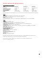
1
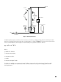
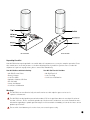
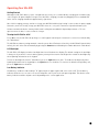
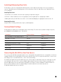
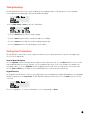
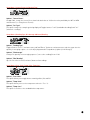
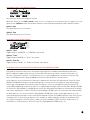
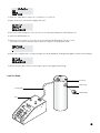
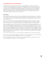
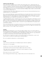
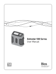
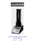
Bios Met Lab Series
ML-500 User Manual
Table of Contents
Introduction................................................................................................................................................................ 2
About Your ML-500..................................................................................................................................................... 2
Theory of Operation................................................................................................................................................................................... 2
Unpacking Checklist ................................................................................................................................................................................. 4
Warnings ................................................................................................................................................................................................... 4
Operating Your ML-500............................................................................................................................................... 5
Getting Started........................................................................................................................................................................................... 5
Turning the ML-500 On & Off . .................................................................................................................................................................. 5
LCD Backlight ........................................................................................................................................................................................... 5
Low Battery Indicator ............................................................................................................................................................................... 5
Using the ML-500 Keypad .......................................................................................................................................... 6
General Menu Navigation ......................................................................................................................................................................... 6
Keypad Function ....................................................................................................................................................................................... 6
ML-500 Menu Tree ..................................................................................................................................................... 7
Error Messages ........................................................................................................................................................................................ 8
Installing & Removing Flow Cells .............................................................................................................................. 9
Factory Default Settings ............................................................................................................................................ 9
Connecting the ML-500 to a Gas Flow Source ............................................................................................................ 9
Taking Readings . ..................................................................................................................................................... 10
Setting User Preferences . ....................................................................................................................................... 10
Using Sensor Factors................................................................................................................................................ 13
Leak Testing . ........................................................................................................................................................... 13
Annual Maintenance and Calibration........................................................................................................................ 15
Recertification...........................................................................................................................................................................................15
Sending Your ML-500 to Bios...................................................................................................................................................................16
Shipping....................................................................................................................................................................................................16
Storage......................................................................................................................................................................................................16
Bios Met Lab Series ML-500 Specifications ............................................................................................................. 17
Limited Warranty...................................................................................................................................................... 18
Accuracy
Reliability
Convenience
1
Introduction
Congratulations! You’ve chosen the Bios Met Lab® Series ML-500, featuring Proven DryCal® Technology. The ML-500
offers you ±0.25% of reading volumetric, ± 0.40% of reading standardized accuracy within a portable primary standard
that’s ideal for both volumetric and mass flow applications where a high degree of measurement accuracy is required.
Before you get started, we recommend taking a few moments to review this manual and familiarize yourself with
the ML-500. If at any time you have questions regarding its operation, please contact Bios through our web site
(www.biosint.com), or call us at 973.492.8400 to speak with one of our knowledgeable customer support representatives.
About Your ML-500
The ML-500 is a positive displacement primary piston prover for gas flow measurements in either pressure or
vacuum applications. Using Proven DryCal Technology, it combines the accuracy of a primary standard with
unequaled speed and convenience.
Volumetric or standardized flow readings are obtained with the push of a button. The ML-500 can be set to take
flow readings manually, (one reading at a time), or automatically in the hands-free continuous auto-read mode.
The ML-500 can be programmed for up to 100 readings in an averaging sequence.
Theory of Operation
The versatile ML-500 can be used to measure the gas flow rates of both pressure and vacuum flow sources. Its
Proven DryCal Technology features a near-frictionless piston and flow cell design that is primary, highly-accurate
and liquid-free, for primary flow measurements of unequaled speed and convenience. For more information about
our patented DryCal Technology, please visit our website at www.biosint.com.
The ML-500 consists of two primary components: The base and the flow cell (there are three interchangeable flow
cell models, each with a designated flow range). The flow cell plugs into the base unit in order to create a complete,
functional ML-500 system. Neither component can operate independently.
The base component houses the main computer and timing crystal. The flow cell is easily fitted into the base unit’s
9-pin connector and two guide pins.
The flow cell performs the actual flow measurements. For this purpose, it houses a “piston and glass assembly”
comprised of a borosilicate glass tube housing a precision-machined piston. The flow cell also contains an
integrated temperature sensor and barometric pressure transducer in the gas flow stream for instant conversion
of the volumetric readings into standardized flow.
The ML-500 can be set to take flow measurements manually, one reading at a time, or automatically in the
Auto-Read mode for hands-free, continuous measurements. The ML-500 can be programmed for up to 100
readings in an averaging sequence.
The ML-500 includes an RS-232 port (serial port), cable and free Bios Optimizer Collect Light software to enable
calibration data to be downloaded to a Microsoft Excel® spreadsheet. Bios Optimizer Collect Light may be upgraded
to Optimizer Collect in order to obtain greater functionality; please contact Bios for information.
2
Vent
Cylinder
Light
Emitter
Photodiode
/ Collimator
Bypass Valve
Piston
Inventory Volume
Absolute
Transducer
Temperature
Transducer
Inlet
Inlet Filter
Figure 1: Primary Piston Prover
An idealized piston prover would consist of a massless, frictionless, leakproof, shape-invariant and impermeable
piston inserted within the flow stream and enclosed by a perfect cylinder (Figure 1). The time that the piston takes
to move a known distance (which implies a known volume) then yields the volumetric flow as:
q = v / t = π r2 h / t
Where:
q = volumetric flow rate
v = measurement volume
t = measurement time
r = radius
h = measurement path length
Such a device would be as accurate as its physical dimensions and its clock, with almost insignificant drift
mechanisms. Although such idealized devices do not exist, we believe that DryCal Technology offers close to
ideal performance.
3
Back and Side
Front and Side
Unpacking Checklist
Your ML-500 has been packaged with care and includes all components necessary for complete operation. Please
take a moment to check that you have received the following items. If you believe you have not received a full
shipment or if you have any questions, please contact Bios immediately.
Your ML-500 Base with the following:
• ML-500 Electronic Base
• Battery Charger
• Leak Test Cable
• Optimizer Software CD-Rom
• RS-232 Cable
• Instruction Manual
• Certificate of Calibration
Your ML-500 Flow Cell Includes
• ML-500 Flow Cell
• Leak Test Plug
• Certificate of Calibration
Warnings
The ML-500 is not rated intrinsically safe and is not for use with explosive gasses or for use in
explosive environments.
The ML-500 is not designed for pressurization above 2 PSI or for gas flows above the rated specifications of
the flow cell in use. Please consult the product specification on the inside front cover of the manual for more
information regarding acceptable gas flow ranges or visit our website at www.drycal.com for the most current
product specifications.
For use with clean laboratory air or other inert, non-corrosive gasses only.
4
Operating Your ML-500
Getting Started
Although the ML-500’s battery comes charged from the factory, we recommend fully charging your new battery by
connecting the AC power adapter/charger to the ML-500’s charging jack and then plugging it into a standard wall
outlet. Initial charging should take approximately eight hours.
After initial charging, you may continue to charge your ML-500 indefinitely by leaving it connected to the power supply.
Otherwise, make sure to fully charge your ML-500 at least once every three months to help maintain battery life.
On bases manufactured after January 2008 a small cooling fan was added for improved performance. The fan
operates when the base is connected to the charger.
Turning the ML-500 On & Off
Press On to start the ML-500. An opening screen will appear indicating the instrument’s revision level followed by
the “Main Menu”.
The ML-500 has a battery saving automatic shut off system. After 65 minutes of inactivity, the ML-500 will shut off. Alternatively, the unit can be shut off manually by pressing the Reset button followed by the number 0 from the “Main Menu”.
LCD Backlight
The ML-500’s LCD display includes a backlight function to illuminate the display. The default setting for the backlight
is always on. If you wish to conserve battery power you may wish to turn the backlight off or enable the backlight only
when inputting information on the keypad.
To turn the backlight off, from the “Main Menu” press the Light button one time. To enable the backlight only when
inputting information on the keypad press the Light button a second time. To return to the default setting (always on),
press the Light button a third time.
Low Battery Indicator
A low battery condition is indicated by a “B” appearing in the upper right-hand corner of the LCD. The low battery
indicator allows the user to connect to an external power source prior to the unit powering down. Time between low
battery indication and loss of power varies depending on the current application.
5
ML-500 Keypad
DryCal ML-500
®
(65-minutes auto-shut off)
Backlight
Li
gh
t
Power button
ON
Met Lab Series
UP
1
2
3
ABC
DEF
GHI
4
5
6
JKL
MNO
PQR
BACK
Use for data entry
ENTER
FWD
Menu navigation
DOWN
7
8
9
STU
VWX
YZ-
Reset
Stop
*
0
#
Auto
Read
Product functions
Using the ML-500 Keypad
General Menu Navigation
Use the Up/Down arrows to navigate between different lines within a menu. Use the Enter button to select a field
to be modified and to lock-in any changes. Use the keypad for data entry, such as entering standard temperature
conditions; use the Up/Down arrows to toggle between fields, such as Temperature or Pressure units. Use the
Fwd and Back keys to advance to the following menu or return to the previous menu.
Keypad Function
The keypad is used for both numeric character entry. When pressed, each alphanumeric button will display its
corresponding number. To go back, use the back arrow. The ML-500 will overwrite previous entries. Use the Enter key
to lock-in any selections.
• Reset Button: Clears both the current reading and the group average and opens the valve, allowing the piston
to return to its resting state.
• Stop Button: Stops current reading and opens the valve, allowing the piston to return to its resting state.
• Auto Button: Initiates automatic readings (must be accessed from the “Run Menu”). If the Reading type has been
set to “Cont” in “Setup Menu - 2”, the unit will run until the preset average is reached and then restart the cycle.
If the Reading type has been set to “Burst” in “Setup Menu - 2”, the unit will run until the preset average is
reached and then stop.
• Read Button: Initiates a single reading (must be accessed from the “Run Menu”).
6
ML-500 Menu Tree
= Forward navigation
= Backward navigation
Press Fwd arrow
after“Menu - 6” to
return to“Main Menu”
• Use the Up/Down arrows to navigate between different lines.
• Use the Enter button to select a field to be modified depending on the function and to lock in any changes.
• Use either the keypad or the Up/Down arrows to modify the desired field.
• Use the Fwd and Back keys to advance to the following menu or return to the previous menu.
7
ML-500 Menu Tree
= Forward navigation
= Backward navigation
To exit at any time, press Reset
• Use the Up/Down arrows to navigate between different lines.
• Use the Enter button to select a field to be modified depending on the function and to lock in any changes.
• Use either the keypad or the Up/Down arrows to modify the desired field.
• Use the Fwd and Back keys to advance to the following menu or return to the previous menu.
ErrorMessages
Messages
Error
Cell is not present
Cell
present or
or unit
unitdoes
doesnot
not"see"
“see”cell.
cell.
To exit,
exit, press
press Back,
Back, or
To
or wait
wait to
to return
returnto
to"Main
“MainMenu"
Menu”.
Piston did
did not
notreturn
returnto
tobottom
bottomofofcell
cellproperly.
properly.
Piston
press any
any key.
key.
To exit, press
8
Installing & Removing Flow Cells
The ML-500 accepts interchangeable ML-500 (only) flow cells for different flow ranges. If the user attempts to
enter the “Run Menu” prior to installing a flow cell, the unit indicates “No Cell” and returns to the “Main Menu” after
a 5 second delay.
Installing Flow Cells
1. Position the selected flow cell into the base opening, its top label facing you.
2. Turn the cell back and forth to locate the guide pins; when the guide pins are engaged, press down.
3. When powered on, the ML-500 senses which cell is installed and displays the appropriate units for that cell.
Removing Flow Cells
Grasp the flow cell firmly, hold the base in place, and lift upwards.
Factory Default Settings
The ML-500 has a number of user-definable features and settings. To return to factory default settings at any time,
press Reset followed by Save from the “Main Menu”.
Parameters
Factory Settings
Optional Settings
No. of Readings in an Averaging Sequence
10
1-100
Atmospheric Pressure
mm Hg
mBar, kPa, PSI
Temperature
ºC
ºF
Standardized Temperature Setting
0 ºC
0.0-50.0 ºC
Date Format
MM/DT/YR
DT/MM/YR
Time Format
AM/PM
24 Hr
Connecting the ML-500 to a Gas Flow Source
The accuracy of the ML-500 is dependent upon its source being stable. An unstable flow source may produce inconsistent
readings. Flow direction is indicated by the arrow on the top of the flow cell. To use a pressure flow source, connect to the
inlet fitting, or to use a vacuum flow source, connect to the outlet fitting.
The M-500 is designed to be used at ambient pressures. Do not subject the ML-500 to a pressure 2 PSI higher or lower
then atmospheric pressure. This is easily accomplished by leaving the outlet of the flow cell open to atmosphere for
pressure applications or the inlet outlet open to atmosphere in vacuum scenarios. If tubing is needed to exhaust test
gases to a fume hood insure that the exhaust tubing is of sufficient diameter such that the pressure to
the ML-500 calibrator does not exceed 2 PSI.
9
Taking Readings
The ML-500 default is preset for ten (10) readings in an averaging sequence. This parameter is user-definable
(see Setup Menu 2, Reading Type, # in Average & Min./Reading).
1. Press Enter, Read, or Auto to enter the “Run Menu”.
• Press the Read button to initiate a single reading.
• Press the Auto button to initiate continuous hands-free readings.
• Press the Stop button to stop current flow reading and open valve.
• Press the Reset button to clear the display of current data.
Setting User Preferences
The ML-500 offers enhanced electronics options to allow the user to define parameters specific to an application.
There are six Setup Menus.
General Menu Navigation
Use the Up/Down arrows to navigate between different lines within a menu. Use the Enter button to select a field
to be modified and to lock-in any changes. Use the keypad for data entry, such as the number of readings in an
averaging sequence; use the Up/Down arrows to toggle between fields, such as Temperature or Pressure units.
Use the Fwd and Back keys to advance to the following menu or return to the previous menu.
Keypad Function
The keypad is used for numeric character entry. When pressed, each alphanumeric button will display its corresponding
number. To go back, use the back arrow. The ML-500 will overwrite previous entries. Use the Enter key to lock-in any
selections.
Press Fwd arrow
after“Menu - 6” to
return to“Main Menu”
To enter “Setup Menu - 1” from the “Main Menu”, select Setup and press Enter.
10
Setup Menu 1, Sensor Factor, Calibration Type
Option 1, “Sensor Factor”
As applicable, change the Sensor Factor from its default value of 1.000 to the value provided by the MFC or MFM
manufacturer (see Using Sensor Factors).
Option 2, “Cal. Type”
This option changes the sample type being displayed. Toggles between “std.” (standardized readings) and “vol.”
(volumetric readings).
Setup Menu 2, Reading Type, # in Average & Minutes/Reading
Option 1, “Reading Type”
Toggles between “Cont.” (continuous auto-read) and “Burst” (performs continuous auto-read, then stops after the
quantity in averaging sequence is reached [as programmed in Setup Menu 2, Option 2, # in Average]).
Option 2, “# in Average”
Changes the quantity in an averaging sequence (consecutive readings) from 1-100.
Option 3, “Min./Reading”
Specifies the time interval (in minutes) between flow readings.
Press Fwd arrow
Setup Menu 3, Pres. Units, Temp.
Units,-Temp
after“Menu
6” to Corr.
return to“Main Menu”
Option 1, “Pres. Units”
This option allows you to toggle between mmHg, mBar, kPa and PSI.
Press Fwd arrow
after“Menu - 6” to
Option 2, “Temp. Units”
return to“Main Menu”
This option allows you to set the temperature units for ° F or ° C.
Option 3, “Temp. Corr.”
This option is used to set the standardization temperature.
Press Fwd arrow
after“Menu - 6” to
return to“Main Menu”
11
Setup Menu 4, Date, Time & Battery Voltage
This menu has an alternate navigation method.
Within this menu, use the Fwd and Back arrows to select each option, such as Month or Day. To change a selected
option, use the Up/Down arrows. Date and time formats are specified using Setup Menu 5, Date and Time Formats.
Option 1, Date
This option allows you to set the date.
Press Fwd arrow
after“Menu - 6” to
return to“Main Menu”
Option 2, Time
This option allows you to set the time.
Setup Menu 5, Date & Time Formats
Option 1, “Date”
Press Fwd arrow
- 6” to date format.
Toggles between ‘’MT/DT/YR’’after“Menu
or ‘’DT/MT/YR’’
return to“Main Menu”
Option 2, “Time”
Toggles between ‘’AM/PM’’ or ‘’24 Hr’’ time format.
Option 3, “Auto Off”
Toggles between ‘’Enable’’ or ‘’Disable’’ 65-minute auto-shut off.
Setup Menu 6, Piston Tare Value (PTV) and Piston Tare Value Multiplier (PTVM)
PTV stands for Piston Tare Value; this is the amount of gas that passes around the piston during measurement.
All Bios calibration equipment has a factory set Piston Tare Value that is stored in the memory of the DryCal cell.
The value is typically very small 0.1 ccm for low flow cells, 0.2 ccm for medium flow cells and 1.4 ccm for the high
flow cells. We adjust for this leakage by adding the Piston Tare Value (PTV) to the measurements.
On our highest accuracy instruments we allow for the adjustment of the Piston Tare Value with the Piston Tare Value
Multiplier (PTVM). When using the instrument with gas species other then air or nitrogen, the molecular behaviors
of these gases may degrade the Piston Tare Value. For highest accuracy, the instrument’s Piston Tare Value (PTV)
can be adjusted. Adjusting the Piston Tare Value is accomplished by entering a new Piston Tare Value Multiplier (PTVM).
The Piston Tare Value Multiplier is multiplied to the Piston Tare Value and used to adjust the measurement; the default
value for air and nitrogen is 1.000. The Piston Tare Value Multiplier (PTVM) can be set to any value from 3.000 to 0.2000.
For flows above 20 ccm, a new a Piston Tare Value Multiplier (PTVM) value can be calculated by using the viscosity
of the gas being measured and accurate results will be obtained. Calculate the PTVM by taking the ratio of the viscosity
of nitrogen to the viscosity of the gas under test. For example, to calibrate hydrogen consider the following: at 0 0C,
the viscosity of nitrogen is 165.31 microPoise, and the viscosity of hydrogen is 83.21 microPoise. Express these as
165.31/83.21, or 1.987, and enter 1.987 as the Piston Tare Value Multiplier (PTVM) for this cell.
12
Press Fwd arrow
When measuring alternate gases
at flows- below
after“Menu
6” to 20 ccm, or for absolute best accuracy, it may be necessary to perform
to“Main
Menu”
a dynamic leak test using thereturn
gas under
test.
Contact Bios for information on this test.
Option 1, “PTV” Piston Tare Value
This is the unique piston tare value of a particular flow cell. It is factored into each flow reading for
leakage-independent measurements. The piston tare value is factory-set and non-adjustable.
Option 2, “PTVM” Piston Tare Value Multiplier
This is the adjustable piston tare value multiplier used to adjust the piston tare value to enhance accuracy at lower
flows when using gasses other than nitrogen or air. The piston tare value multiplier’s factory setting is 1.000,
although it may be changed to any value between 0.200 and 3.00 if gasses other then air or nitrogen are used.
Using Sensor Factors
When calibrating an MFC or MFM using a surrogate or proxy gas (meaning the MFC or MFM was originally calibrated
by the manufacturer for a gas other than what you are currently using), the reading of the ML-500 can be scaled by the
sensor factor to allow for this.
To enable your ML-500 to scale its actual flow measurements to match the adjusted flow from the MFC or MFM, input
the sensor factor into the ML-500 before calibrating the MFC or MFM (see SETUP – Readings).
The Sensor Factor is displayed on the run screen of the ML-500 as SF X.XXX. The default setting is 1.000. Because a
sensor factor other than your ML-500’s default value of 1.000 modifies the actual flow to a “reported” flow make sure
to change this setting back to 1.000 when a calibration involving the use of a sensor factor is completed.
Leak Testing
To ensure proper function of the ML-500 annual factory calibration is recommended. However, a quality assurance
self-test feature is provided to verify proper integrity of the flow cell. It is recommended that the self-check leakage
test be conducted periodically as part of an ongoing quality assurance program. Passing the leak test does not ensure
proper function of the ML-500, although it does ensure that total leakage is within the product’s allowable limits. The
leak test may take as long as 6 hours or more to complete per fitting. Since the leak test may take several hours, it is
recommended to plug the charger into the base during the leak test to prevent unit from turning off.
When performing the leak test procedure note the inlet and outlet leakage. If the inlet and outlet leakage do not agree
within 50% of each other, assure that the inlet and outlet Fittings are tight, then repeat the leak test procedure. If the
problem persists, please contact Bios.
The maximum leakage limits are .200 ccm for the ML-500-10; 1.000 ccm for the ML-500-24; and 3.000 ccm for the
ML-500-44. If the leakage exceeds the maximum limits, repeat the leak test procedure. If the problem persists,
please contact Bios for assistance.
To Initiate the Leak Test
1. Place the ML-500 on a flat, vibration-free surface.
2. While in the ‘’Main Menu’’ install the leak test cable (included with the ML-500 base unit)
between the 9-pin ML-500 Base Connector and the 9-pin Cell Connector.
13
3. From the ‘’Main Menu’’ remove the cell and select ‘’Leak Test’’.
4. After a leak test is initiated, the display will read:
5. Place the leak test plug over either the inlet or the outlet port fitting on the ML-500 flow cell.
6. Invert the ML-500 flow cell.
7. Push any key to commence the leak test. At this point the ML-500 will time the descent of
the piston. The leak test may take up to 6 hours to complete. The display will read:
8. If the test is completed successfully a leakage rate will be displayed. The display will appear similar to the following:
9. Repeat the procedure with the leak test port cap over the opposite port fitting.
Leak Test Setup
Inverted Cell
Leak Test Plug
Leak Test Cable
Swagelok Fitting
Base
14
Annual Maintenance and Calibration
Your ML-500 is engineered to provide years of reliable service, with appropriate care and maintenance. Bios
recommends an annual calibration by our ISO 17025–accredited laboratory, to help ensure the best possible flow
measurements and to provide a bullet-proof audit trail for those applications subject to regulatory requirements.
If you should encounter any problems with your ML-500, immediately contact Bios Customer Service and provide a
detailed description of your situation, including ML-500 model and serial number, information about the flow source
and the current calibration setup, environmental conditions during the test, the flow point or points that you’re
checking and an explanation of the issue you’re experiencing.
Recertification
Your ML-500 primary piston prover is a precision measuring standard comprised of moving parts that are machined
to extremely close tolerances. Additionally, various environmental factors, product wear, drift of the temperature
sensors and pressure transducers, or inadvertent damage may adversely affect your ML-500’s measurement accuracy
or general performance.
For these reasons, Bios highly recommends having your ML-500 annually verified by our ISO 17025–accredited
laboratory in order to ensure its measurement integrity. For those applications subject to regulatory or ISO requirements, verification by our accredited laboratory provides you with a defensible audit trail of the highest quality.
As the ultimate quality assurance measure, as well as to keep your ML-500 in top condition and updated with the latest
hardware and firmware upgrades (as available), Bios offers our elective Recertification program. Recertification is an
intensive service and calibration package that provides pre- and post-dynamic flow comparisons against our Proven
DryCal Technology lab standard; complete product refurbishment - including cleaning of the piston and glass assembly,
installation of any available upgrades and other routine and preventative maintenance items; and full dimensional calibration, comprised of 20 or more tests using precision instruments and gauges, such as depth and laser micrometers
and a temperature bath. When completed, you receive NIST-traceable, ISO 17025-, ANSI Z-540- and NIST Handbook
150-backed calibration certificates.
Recertification includes a 90-day service warranty should any related labor or parts replacements prove faulty.
Due to the intensive nature of our ML-500 Recertification, the time spent within our New Jersey facility during this
process is generally fourteen days, beginning from the day we receive your product.
For a detailed explanation of our Recertification process, our laboratory and our accreditation, please visit our
website at www.biosint.com and visit the Service & Support page.
15
Sending Your ML-500 to Bios
Please contact Bios for an RMA (return merchandise authorization) number before sending your ML-500 to our
factory for elective Recertification or other service. You can get an RMA number through our automated web-based
system at at www.biosint.com/ContactUs/rmaform.aspx; by emailing [email protected]; or, by calling us directly at
973.492.8400. Please make sure to check out our Bios Quality, Service and Calibration document located through the
Service & Support page on our web site. This document provides full RMA procedures and other useful information
to assist you in this important process.
Sending your ML-500 to Bios without an RMA number may result in return of the instrument without inspection or a
substantial delay in service turnaround time.
When requesting your RMA number, provide your ML-500 model, serial number and revision level. Also, describe any
product issues you may be experiencing. Please keep in mind that Bios will not begin evaluation and service of your
ML-500 until you have accepted and approved, in writing, our formal RMA quote for service. This protects both you
and Bios during this process and ensures a fair and efficient service experience.
If sending your ML-500 for repair or evaluation (rather than elective Recertification), please contact Bios for technical
support or troubleshooting assistance prior to shipping the unit. We will first attempt to resolve the situation over the
phone or via email. If you’ve provided us with a detailed description of your ML-500 issue and application details and
we’re unable to resolve the situation by telephone or email, we’ll issue you an RMA number for the prompt return of
your ML-500 for evaluation.
Please note that Bios will make every attempt to verify your issue, as we want you to get the most out of your ML-500.
However, if we are unable to detect a product issue or if we determine that the issue is application-related rather than
product-related, we reserve the right to charge an evaluation fee.
Shipping
When shipping your ML-500, please ensure that the packaging is adequate to protect the instrument. Whenever
possible, your ML-500 should be shipped in its original packaging or within a hard case, such as a Pelican carrying
case (available for purchase from Bios). We highly recommend using a standard freight carrier (e.g., FedEx, UPS)
that supplies tracking numbers and insuring the product against damage in transit.
Bios is generally not responsible for freight cost associated with shipments to and from Bios, except in certain
instances; please contact Bios for information before initiating a shipment.
Bios is not responsible for damage that occurs during shipment.
Storage
If you need to store your ML-500 for an extended period, please follow these guidelines:
Always store it in a clean, dry place.
If possible, leave it attached to its AC power adapter/charger while in storage.
If your ML-500 cannot be attached to its AC power adapter/charger while in storage:
ully charge it before extended storage. If the battery isn’t fully charged prior to storage,
F
it might be permanently damaged.
Fully charge it at least once every three months.
When removing your ML-500 from storage, recharge the battery for at least 12 hours prior to use.
16
Bios Met Lab Series ML-500 Specifications
Interchangeable Flow Cell Models:
Model
ML-500-10 ML-500-24
ML-500-44
Flow Range Accuracy, Standardized Accuracy, Volumetric Time Per Reading Weight 5—500 sccm ±0.40% ±0.25% 1—80 seconds
85.1 oz / 2412.5 g
50—5,000 sccm
±0.35%
±0.20%
1—50 seconds
86 oz / 2439.3 g 500—50,000 sccm
±0.40%
±0.25%
1—20 seconds
88.4 oz / 2507 g
Specifications based on averaged readings. Accuracy is stated as a percent of reading (including standardization, if applicable).
Basics:
Dimensions: Base (H x W x D) 3.9 x 5.25 x 10.67 in / 99 x 133 x 271 mm
Dimensions: Cell (H x W x D) 10.15 x 6 x 4 in / 258 x 152 x 102 mm
Weight: Base 43.5 oz / 1233 g
Gas Compatibility Non-corrosive, non-condensing, non-combustible gasses. Less than 70% humidity.
Usage:
Flow Mode: Suction and Pressure
Configuration: Base with modular, interchangeable flow cells (three)
Temperature & Pressure Sensors: Yes, in the flow stream of each interchangeable flow cell
Reading Modes: Single, Auto or User-Specified Burst
AC Adapter/Plug: 12V DC, > 500 ma, 2.5 mm, center positive, North American standard, others available
Battery Type: 6 volt lead acid.
Inlet and Outlet Fittings: Swagelok™
Ambient Temperature: 15–30° C
Storage Temperature: 0–70° C
Ambient Humidity: 0–70%, non-condensing
Display: Backlit LCD
Operating Pressure (Absolute): 15 PSI
Data Port: Serial
Warranty: 1 year; battery 6 months
Bios highly recommends annual Recertification (product maintenance, pre and post dynamic flow comparisons and
full dimensional calibration). This is elective and is not included as a warranty item.
All specifications are subject to change. Please contact Bios or visit our web site at www.biosint.com for
the most current product information.
17
Limited Warranty
The Bios Met Lab Series ML-500 is warranted to the original end user to be free from defects in materials and workmanship under normal use
and service for a period of one year from the date of purchase as shown on the purchaser’s receipt. The Bios Met Lab Series ML-500’s battery is
warranted for six months from the original purchase date. If the unit was purchased from an authorized reseller, a copy of an invoice or packing slip
showing the date of purchase may be required to obtain warranty service.
The obligation of Bios International Corporation under this warranty shall be limited to repair or replacement (at our option), during the warranty
period, of any part that proves defective in material or workmanship under normal use and service, provided the product is returned to Bios
International Corporation, transportation charges prepaid.
Notwithstanding the foregoing, Bios International Corporation shall have no liability to repair or replace any Bios International Corporation product:
1.That has been damaged following sale, including but not limited to damage resulting from improper electrical voltages or currents,
defacement, misuse, abuse, neglect, accident, fire, flood, terrorism, act of God or use in violation of the instructions furnished by Bios
International Corporation;
2.When the serial number has been altered or removed; or,
3.That has been repaired, altered or maintained by any person or party other than Bios International Corporation’s own service facility or a
Bios authorized service center, should one be established.
This warranty is in lieu of all other warranties, and all other obligations or liabilities arising as a result of any defect or deficiency of the product,
whether in contract or in tort or otherwise. All other warranties, expressed or implied, including any implied warranties of merchantability and
fitness for a particular purpose, are specifically excluded.
In no event shall Bios be liable for any special, incidental or consequential damages for breach of this or any other warranty,
express or implied, whatsoever.
Bios International Corporation
10 Park Place
Butler, NJ, USA 07405
Phone: 973.492.8400
Toll Free: 800.663.4977
Fax: 973.492.8270
Email: [email protected]
web: www.biosint.com
© 2009 Bios International Corporation MK01-32 Rev E
18