1
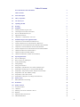
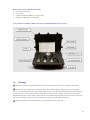
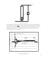
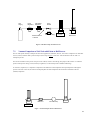
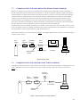
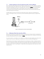
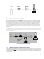
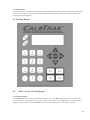
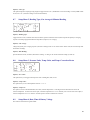
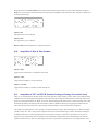
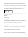
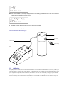
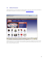
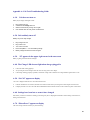
Instruction Manual
Revision A.2
May 2007
Cal=Trak SL-800 Primary Gas Flow Calibrator
Instruction Manual
Revision A3
June 2008
Worldwide Locations to Serve You
CORPORATE HEADQUARTERS
5 Harris Court, Building L Monterey, CA, 93940 USA
Phone (831) 373-0200 (800) 866-0200
Fax (831) 373-4402
www.sierrainstruments.com
EUROPE HEADQUARTERS
Bijlmansweid 2, 1934RE Egmond a/d Hoef, The Netherlands
Phone +31 72 5071400 Fax +31 72 5071401
ASIA HEADQUARTERS
Room A618, Tomson Centre
188 Zhang Yang Rd, Pu Dong New District, Shanghai, PR China 200122
Phone + 8621 5879 8521
Fax +8621 5879 8586
2
Table of Contents
Sierra Instruments Contact Information
2
Table of Contents
3
1.0
General Description
5
2.0
Theory of Operation
5
3.0
Cal=Trak Layout
7
4.0
Unpacking Checklist
7
5.0
Warnings
8
6.0
Installation
9
6.1
Attaching and Removing Flow Cells
9
6.2
Connecting the Cal=Trak to a Flow Source
9
6.3
The Cal=Trak Measurement Cycle
9
6.4
Application Precautions
11
6.5
Comparison vs. Calibration, the “4-to-1 rule”
11
7.0
Installation Diagrams and Application Guide
12
7.1
Comparison of Cal=Trak with Piston or Bell Provers
12
7.2
Vacuum Comparison of Cal=Trak with Piston or Bell Provers
13
7.3
Comparison of Cal=Trak with Laminar Flow Element Transfer Standards
14
7.4
Comparison of Cal=Trak with Sonic Nozzle Transfer Standards
14
7.5
Vacuum Comparison of Cal=Trak with Sonic Nozzle Transfer Standards
15
7.6
Calibration of Mass Flow Controllers (MFCs)
15
7.7
Calibration of Mass Flow Meters (MFMs)
16
7.8
Calibration of Rotameters (Variable Area Flow Meters)
16
8.0
Operating Instructions
17
8.1
The Cal=Trak Keypad
18
8.2
How to Use the Cal=Trak Keypad
18
8.3
Factory Default Settings
19
8.4
Taking Readings
19
8.5
Setting User Preferences
20
8.6
Setup Menu 1, Calibration ID #, Gas Constant, Calibration Type
20
8.7
Setup Menu 2, Reading Type, # in Average, Minutes/Reading
21
8.8
Setup Menu 3, Temp. Correction Factor, Temp. & Pressure Formats
21
8.9
Setup Menu 4, Date, Time & Battery Voltage
21
8.10
Setup Menu 5, Date & Time Formats
22
8.11
Setup Menu 6, Leakage & LCF (Leakage Correction Factor)
22
9.0
Battery System
22
9.1
Battery Maintenance and Storage
22
10.0
Maintenance
22
11.0
Quality Assurance
23
11.1
Leak Test Procedure
23
11.2
Calibration
24
11.3
Returning Your Unit for Calibration or Service
25
14.4
Shipment
25
11.5
Replacement Parts & Accessories
25
11.6
Additional Information
26
3
12.0
Limited Warranty
27
Appendices
A
Cal=Trak Trouble Shooting Guide
28
B
Cal=Trak Specifications
31
C
Cal=Soft Communication Program
32
4
1.0
General Description
The Sierra Cal=Trak SL-800 is the most accurate commercially available gas flow calibrator. Using near-frictionless piston technology, it
combines the accuracy of a primary standard with unequaled speed and convenience.
The Cal=Trak consists of two primary sections. The base houses the main computer, time base and barometric pressure sensors while the
flow cell performs the actual physical measurements using a precision-machined graphite composite piston and borosilicate glass tube. The
flow cell also contains the integrated temperature sensor. The base has 9-pin connector and two guide pins on its upper surface into which
the interchangeable flow cells are installed.
Mass (Standardized) or volumetric flow readings are obtained with the push of a button. The Cal=Trak can be set to take flow readings
manually, one reading at a time, or automatically, in the auto-read mode. The Cal=Trak can be programmed for up to 100 readings in an
averaging sequence. It can be used to measure gas flow rates from most positive pressure sources or under vacuum. Please contact Sierra
Instruments for special precautions before using your Cal=Trak under vacuum.
The Cal=Trak includes a convenient LCD user interface in the base unit. In addition, an RS-232 port for computer interface capability is
provided. An Application program for downloading data from Cal=Trak into Microsoft Excel is on the included CD-ROM. See Appendix
C: Cal=Trak Software Instructions for Data Downloading at the end of this Manual.
2.0
Theory of Operation
The Sierra Cal=Trak SL-800 is a true primary gas standard. The time required for the graphite composite piston to traverse a known
distance through the flow cylinder is precisely measured and an internal computer calculates the flow. The volumetric accuracy of the
instrument is built into its dimensional characteristics. Standardization of the gas flow readings to obtain mass flow is achieved with
precisely calibrated temperature and pressure sensors.
Piston provers like the Cal=Trak are characterized by the most basic of quantities: length and time. As flow is necessarily a derived unit, a
dimensionally characterized system would be as close as possible to direct traceability from national dimensional standards.
An idealized piston prover would consist of a mass-less, friction-less, leakproof, shape-invariant and impermeable piston inserted within the
flow stream and enclosed by a perfect cylinder. The time that the piston takes to move a known distance (which implies a known volume)
then yields the volumetric flow Q as:
Q = V / T = πr2 h / T
Where:
•
V is measured volume
•
T = measurement time
•
r = radius of cylinder
•
h = length (height) of measurement path
Such a device would be as accurate as its physical dimensions and its clock, with almost insignificant drift mechanisms. Although such
idealized devices do not exist, we believe the Cal=Trak offers close to ideal performance (Figure 1).
The Cal=Trak clearance-sealed prover uses a piston and cylinder fitted so closely that the viscosity of the gas under test results in a leakage
small enough to be insignificant. For reasonable leakage rates, such a gap must be approximately 10 microns. As a practical matter, the
piston and cylinder are made of graphite and borosilicate glass because of their low, matched temperature coefficients of expansion and low
friction.
5
Vent
Cylinder
Light
Emitter
Photodiode
/ Collimator
Bypass Valve
Piston
Inventory Volume
Inlet
Inlet Filter
Figure 1 Idealized Automatic Piston Prover
In order to make an intrinsically volumetric device useful for measurement of gases, it is generally necessary to adjust the readings to a
standardized temperature and pressure, yielding mass flow. For this reason, we include temperature and pressure transducers to allow
computation of standard (mass) flow by the internal computer (Figure 2).
Vent
Cylinder
Light
Emitter
Photodiode
/ Collimator
Bypass Valve
Piston
Inventory Volume
Absolute
Transducer
Temperature
Transducer
Inlet
Inlet Filter
Figure 2 Practical Piston Prover
6
3.0 Cal=Trak Layout
4.0
Unpacking Checklist
Your Sierra Cal=Trak has been packaged with care and includes all components necessary for complete operation. Please take a moment to
check that you have received the following items. If you believe you have not received a full shipment or if you have any questions, please
contact Sierra immediately.
Your Cal=Trak SL-800 Base Includes
•
Cal=Trak SL-800 Electronic Base
•
Battery Charger
•
Leak Test Cable
•
RS-232 Cable
•
Instruction Manual
•
Certificate of Calibration (behind top cover foam insert)
•
Warranty Card (behind top cover foam insert)
•
Cal=Soft CD-ROM (Application software for downloading data to your computer and making calibration certificates)
7
Each of Your Cal=Trak SL-800 Flow Cells Includes
•
Cal=Trak SL-800 Flow Cell
•
Leak Test Plug
•
Certificate of Calibration (behind top cover foam insert)
•
Warranty Card (behind top cover foam insert)
If you purchased your calibrator with the Cal=Trak case, it should look like this when you receive it:
5.0
Warnings
The Sierra Cal=Trak is not rated intrinsically safe and is not for use with explosive gasses or for use in explosive environments.
The Sierra Cal=Trak is designed for use at ambient pressures. This is easiest to obtain by leaving the outlet open to atmospheric
pressure. For vented applications, up to 5 inches of water column (12 mbar or 0.18 PSI) at the outlet fitting maybe used without impact on
measurement accuracy. More than this pressure will add additional uncertainty to the flow readings. Do not use the Cal=Trak with a
differential pressure above 0.35 bar (5 PSI). In other words, the pressure differential across the flow cell must be less than 0.35 bar or the
flow cell may be damaged. Please visit www.sierrainstruments.com for the most current product specifications.
The Sierra Cal=Trak is for use with clean laboratory air or other inert, non-corrosive gases only.
8
6.0
Cal=Trak Installation
6.1
Attaching & Removing Flow Cells
The Sierra Cal=Trak accepts interchangeable cells for different flow ranges. If user tries to enter “Run Menu” prior to installing a flow cell,
the unit indicates “No Cell” and returns to the “Main Menu” after a 5 second delay.
Attaching Flow Cells
1. Position the selected flow cell into the electronics base opening with its silver Sierra Instruments label facing you.
2. Locate the guide pins; when the guide pins are engaged, press down firmly.
3. When the power is turned on, the base electronics will sense which cell is installed and display the appropriate units for that cell.
Removing Flow Cells
Grasp the flow cell firmly by the base of the cylinder and lift upward out of the base.
6.2
Connecting the Cal=Trak to a Flow Source
As the accuracy of the Cal=Trak is dependent upon the mechanical set-up (plumbing) of the device under test, it is useful to review the
basic operation of the calibrator prior to plumbing. Always remember the following important guidelines:
1.
The accuracy of the Cal=Trak is dependent upon its source being stable. An unstable flow source may produce inconsistent
readings.
2.
Sierra Instruments’ Cal=Trak is designed to be used at ambient pressures. This is easily accomplished by leaving the outlet of the
flow cell open to atmosphere for positive pressure installations or the inlet open to atmosphere for vacuum installations. If a vent
hose is required on the outlet fitting, a maximum pressure of 5 inches water column (0.18 psi or 12 mbar) above ambient is
acceptable. Exhaust pressure of more than this amount will add additional uncertainty to the flow measurements of Cal=Trak.
One way to reduce exhaust pressure is to increase the diameter of the vent line. Do not subject the Cal=Trak to a differential
pressure above 0.35 bar (5 PSI). In other words, the pressure drop across the Cal=Trak calibrator must not exceed 0.35 bar (5
PSI) or damage may occur. In vacuum scenarios, make certain that the pressure drawn across the Cal=Trak does not exceed 0.35
bar (5 PSI).
3.
Flow direction is indicated by the arrow on the top of the flow cell. To use a pressure flow source, connect to the inlet fitting, or
to use a vacuum flow source, connect to the outlet fitting.
6.3
The Cal=Trak Measurement Cycle
Operation of a Cal=Trak is extraordinarily simple, and little training is required. However, any measurement interacts with the device being
calibrated to some degree. Often, these interactions are negligible. However, sometimes device interactions can seriously affect
measurement accuracy. Here we will explain what happens during a Cal=Trak measurement to aid in installing and using the instrument
appropriately.
In its inactive state, the Cal=Trak will, like any device, exhibit a constant insertion pressure drop. At all but the highest flows, the pressure
drop is very small. In the inactive state, gas flows from the inlet to the outlet through the bypass valve (Figure 3). When a measurement
cycle begins, the bypass valve closes, and the gas is directed into the cylinder, effectively inserting the piston in series with the gas flow,
allowing measurement. Timing commences after the piston has accelerated to the flow stream’s speed. At the end of the timed cycle, the
valve opens and the piston falls to its inactive position at the bottom of the cylinder.
9
O utlet
B ypass V alve
P iston
Inlet
Figure 3 Basic Piston Prover
In real-world applications, there are significant dynamics to consider. At the beginning of a cycle, pressure rises rapidly until the piston
accelerates to the speed of the flow stream. Figure 4 is an illustration of a typical Cal=Trak’s internal pressure during a measurement cycle.
A near-maximum flow rate is illustrated to accentuate the pressure variations. The initial pressure pulse, lasting some tens of milliseconds,
reaches a peak of about 0.5 kPa, or 0.5% of its working, near-atmospheric pressure. The pressure settles out to about 0.1 kPa (0.1% of
working pressure) during the timed period. This pressure represents the added pressure due to the weight of the piston. Very small
oscillations continue due to the piston’s under damped nature.
0.8
Init ial Pressure Pulse
0.6
Int racell Pressure (k Pa)
0.4
Tim ing
Begins
Tim ing
Ends
0.2
0
0
-0.2
100
200
300
400
500
600
M illiseconds
700
800
900
1000
-0.4
-0.6
-0.8
Figure 4 Cal=Trak Internal Pressure
10
6.4
Application Precautions
Although the Cal=Trak’s dynamic pressure effects are very small, in some circumstances they may affect the measurement or interact with
the device under test. For the above reasons, certain precautions should be observed when using a Cal=Trak.
Initial Pressure Pulse
The initial pressure pulse is small, about 1% of an atmosphere or less. However, even so small an increase may affect some very sensitive
transducers for several seconds. Two examples of this are the resonant transducers used in LFE systems such as the DH Instruments
Molbloc or capillary-based systems. For this reason, the LFE instrument may not be accurate for a number of seconds after the start and the
end of a Cal=Trak measurement cycle. When calibrating such systems, a stable flow source should be used and the LFE read before and
after the Cal=Trak cycle.
Intra-Cycle Pressure Change
After the initial brief pressure pulse, the change in insertion pressure is typically 0.1% of an atmosphere (~0.1 kPa or 1 cm water column).
This is usually insignificant. For example, flow from a 100 kPa gauge pressure (15 psi) source will change by 0.1%. However, very low
pressure sources will show larger flow change during a Cal=Trak cycle and may require compensating calculations to achieve Cal=Trak’s
best applied accuracy.
Inventory (Dead) Volume
Inventory volume consists of all the space contained between the flow source’s point of restriction and the timed portion of the cylinder.
This includes tubing, empty space within the Cal=Trak base, the lower portion of the measuring cylinder and any other space contained
within the test setup.
It is important to keep inventory volume to a minimum. Excess inventory volume amplifies the effects of minute pressure variations within
the Cal=Trak cell. In extreme cases, the excess volume also prevents gas pressure from accelerating the piston properly, causing significant
errors in readings. Ideally, the volume contained between the cell and the flow source should be on the order shown in Table 1, which also
shows the volume as an equivalent length of tubing.
Table 1 Recommended Maximum External Volume and Tubing Lengths
Recommended Max.
6.5
Recommended Maximum Length—meters (inches)
Cell Size
Volume (cc)
3mm ID (1/8“)
6mm ID (1/4“)
9mm ID (3/8“)
Small (SL-500-10)
9
1.2 (47.2”)
0.3 (11.8”)
N/A
Medium (SL-500-24)
46
6.5 (256”)
1.6 (63.0”)
0.7 (27.6”)
Large (SL-500-44)
118
16.7 (658”)
4.2 (165”)
1.9 (74.8”)
Comparison vs. Calibration
Calibration consists of comparing an instrument with one of significantly greater accuracy (ideally, at least four times the accuracy of the
device under test--the “4 to 1 rule” widely accepted by industry). We use the term “comparison” in most of the following applications
because, depending upon their respective accuracies, either device can be calibrating (or simply compared with) the other.
For example, a 0.2% LFE can calibrate a 1% mass flow controller, while a 0.15% Cal=Trak can calibrate a 0.6% LFE. On the other hand, a
0.15% lab prover cannot calibrate a 0.15% Cal=Trak to its rated accuracy (or vice-versa). One can calibrate the other to only 0.3% with
great certainty, so we simply call it a comparison.
11
7.0
Installation Diagrams and Application Guide
7.1
Comparison of Cal=Trak with Piston or Bell Provers
Piston or bell provers have a much longer measurement time than the Cal=Trak. For this reason, it is possible to compare them
simultaneously, but certain precautions must be observed. When the Cal=Trak begins its cycle, the piston’s weight causes the internal
pressure to rise by about 0.001 atmospheres (~0.1 kPa). If a simple pressure regulator feeds the test chain, we are simply using the
resistance of the entire flow chain to set our flow rate. The rate will then change significantly when the Cal=Trak is in its measurement
cycle. This will cause the actual flow measured during the Cal=Trak cycles to be less than the average flow seen by the piston or bell
prover.
To render this effect insignificant, the flow must not be affected significantly by the Cal=Trak’s cyclic pressure increase. This can be
achieved by use of a sonic nozzle as the stable flow source, or by feeding a fixed restrictor with a precisely regulated pressure of more than
200 kPa, as is used in factory calibration of the Cal=Trak. Note that at 200 kPa (30 PSI), the dynamic flow decrease of a simple restrictor
caused by the piston’s weight will be about 0.05%. In certain circumstances, the sonic nozzle or porous plug flow generator may be
replaced with a mass flow controller (MFC) specifically tailored to this task. An example is the Sierra Model C100L-10, -24 and -44, each
specifically built to provide a stable flow source for the Cal=Trak calibrator.
For this type of calibration, we can use the setup shown in Figure 5. The adjustable regulator is used to set the flow rate within the range of
a properly sized flow restrictor. A piston or bell prover cycle is instituted. The Cal=Trak and the prover can then be alternately measured
using the fixed flow source.
Gas
Supply
Fixed
Regulator
Adjustable
Regulator
Sonic
Nozzle
DryCal
Cal=Trak
Stable Pressure
> 200 kPa
OR Porous Plug
Piston or
Bell Prover
Figure 5 Setup for Piston or Bell Provers
An alternative approach can be used with piston provers, as shown in Figure 6. A cycle is initiated on the prover, which is much slower than
a Cal=Trak. The Cal=Trak is then started in a cyclical mode, averaging its flow. Before the prover ends its cycle, the Cal=Trak is stopped
and the average flow read.
The Cal=Trak can be set for sufficient cycles in its average to allow interruption by the “stop” button, or smaller averages, such as 5 or 10
readings, can be taken during the prover cycle. It should be noted that the periodic pressure pulses might cause oscillations in bell provers,
reducing the bell prover’s accuracy somewhat.
12
Gas
Supply
Fixed
Regulator
Adjustable
Regulator
Stable Pressure
> 200 kPa
Sonic
Nozzle
OR Porous Plug
Cal=Trak
DryCal
Piston or
Bell Prover
Figure 6 Alternative Setup for Piston Provers
7.2
Vacuum Comparison of Cal=Trak with Piston or Bell Provers
The Cal=Trak operates similarly in both pressure and suction applications. Sometimes, however, users wish to compare the Cal=Trak under
suction (vacuum) conditions. With a piston or bell prover, the setup of Figure 7 can be used. Note that the inlet to the Cal=Trak is at
atmospheric pressure.
The restrictor should be sized to provide a drop of at least 70 kPa (21 inches or 500 mm Hg). The purpose of the restrictor is to render the
piston insertion pressure change (0.1 kPa) relatively insignificant, as in the similar pressure calibration methodology.
In volumetric, comparisons, it is important to compensate for the difference in outlet temperature from input temperature. Although the
pressure is the same on each end, the restrictor and the pump affect the outlet temperature and flow must be normalized to the inlet
(ambient) temperature.
Restrictor
Vacuum Pum p
DryCal
Cal=Trak
Figure 7 Vacuum Setup for Piston or Bell Provers
13
7.3
Comparison of Cal=Trak with Laminar Flow Element Transfer Standards
When the Cal=Trak begins its cycle, the piston’s acceleration causes the internal pressure to spike briefly by about 0.01 atmosphere (~1
kPa). The pressure then remains elevated by about 0.001 atmosphere (~0.1 kPa) due to the piston’s weight. If a simple pressure regulator
feeds the test chain, we are simply using the resistance of the entire flow chain to set our flow rate. The rate may then change significantly
when the Cal=Trak is in its measurement cycle. This will cause the actual flow measured during the Cal=Trak cycles to be less than the
average flow seen by the laminar flow element (LFE). Moreover, the initial pressure pulse may cause the LFE instrument’s sensitive
pressure transducers to be destabilized for several seconds. For the latter reason, the LFE instrument should be read only immediately
before the Cal=Trak reading, and afterward only when the LFE instrument’s readings stabilize. At low flows, the Cal=Trak measurement
may take sufficient time to allow LFE stabilization. In that case, the instruments can be read simultaneously.
In addition, the flow must not be affected significantly by the Cal=Traks’s cyclic pressure increase. This can be achieved by use of a sonic
nozzle as the stable flow source, or by feeding a fixed restrictor with a precisely regulated pressure of more than 200 kPa. (At 200 kPa [30
PSI], the dynamic flow decrease caused by the piston’s weight will be about 0.05%.)
For this type of calibration, we can use the setup shown in Figure 8. The adjustable regulator is used to set the flow rate within the range of
a properly sized flow restrictor.
Gas
Supply
Fixed
Regulator
Sonic
Nozzle
Adjustable
Regulator
Stable Pressure
> 200 kPa
LFE M eter
OR Porous Plug
DryCal
Cal=Trak
Figure 8 Setup for LFEs
7.4
Comparison of Cal=Trak with Sonic Nozzle Transfer Standards
A high quality sonic nozzle used above its critical pressure ratio will supply a constant flow despite changes in its outlet pressure. For this
reason, a calibrated sonic nozzle can be compared to a Cal=Trak by simply connecting its outlet to the Cal=Trak’s inlet as shown in
Figure 9.
Pressure
Transducer
Fixed
Regulator
Adjustable
Regulator
Sonic Nozzle
DryCal
Cal=Trak
Stable Pressure
> Critical
Figure 9 Setup for Sonic Nozzle Transfer Standard
14
7.5
Vacuum Comparison of Cal=Trak with Sonic Nozzle Transfer Standards
The Cal=Trak operates similarly in both pressure and suction applications. Sometimes, however, users wish to compare the Cal=Trak under
suction (vacuum) conditions. With a calibrated sonic nozzle, a simple setup such as that shown in Figure 10 can be used with the inlet to the
Cal=Trak flow cell at atmospheric pressure. There is one precaution, however. The sonic nozzle’s pressure must be measured during the
Cal=Trak cycle to obtain the actual flow that the Cal=Trak is measuring. In turn, the pressure transducer must not be upset by the
Cal=Trak’s initial pressure pulse and must have rapid response relative to the Cal=Trak cycle time. This method is therefore most suitable
for flows in the lower part of a Cal=Trak’s range.
It should be noted that cycling of the Cal=Trak would cause a slight change in the nozzle’s inlet pressure. Even though the pressure
transducer is read during the Cal=Trak cycle, the nozzle may not achieve internal thermal equilibrium during the cycle, slightly reducing
accuracy.
Pressure
Transducer
Sonic Nozzle
Vacuum Pum p
DryCal
Cal=Trak
Stable Pressure
> Critical
Figure 10 Vacuum Setup for Sonic Nozzle Transfer Standard
7.6
Calibration of Mass Flow Controllers (MFCs)
Modern mass flow controllers have fast response times on the order of milliseconds. They can simply be connected to an appropriate inert
gas source and their output stream applied to the Cal=Trak, as in Figure 11. Proper calibration consists of comparing the Cal=Trak reading
to the MFCs actual indicated flow and not to its control signal.
If a slow flow controller is to be calibrated, it is best to calibrate it in its metering mode. Apply the appropriate signal to fully open the
controller’s internal valve (full scale or digital “open), and calibrate the device as shown for mass flow meters (MFMs), below.
Remember that the Cal-Trak is designed to be operated at ambient pressure. If the outlet pressure of the MFC is atmospheric, then Figure 9
is correct. If the outlet pressure of the MFC is above ambient, insert a back-pressure regulator and a pressure gauge between the MFC and
the Cal=Trak. Adjust the back pressure regulator until the pressure gauge reads the correct pressure for the MFC under test (usually the
same pressure the device will see in its normal operation). Calibrate under the actual operating pressures with the outlet of the Cal=Trak at
atmospheric pressure.
15
Gas
Supply
Adjustable
Regulator
M FC
DryCal
Cal=Trak
Figure 11 Setup for Calibrating MFCs
7.7
Calibration of Mass Flow Meters (MFMs)
Mass flow meters can be calibrated with the setup of Figure 12, which is similar to that shown for LFE transfer standards. Again, the flow
must not be affected significantly by the Cal=Trak’s cyclic pressure increase. This can be achieved by use of a sonic nozzle as the stable
flow source, or by feeding a fixed restrictor with a precisely regulated pressure of more than 200 kPa. (At 200 kPa [30 PSI], the dynamic
flow decrease caused by the piston’s weight will be about 0.05%.) Alternately, a stable mass flow controller may be used to maintain
specific flows into the MFM under test. In this scenario, the MFC will function as a pressure stabilizer and precision flow regulator with
the Cal=Trak defining the accuracy of the device under test. Contact Sierra Instruments for special Smart-Trak flow controllers designed
for this application.
If the MFM under test must be calibrated at pressure (i.e. because it is always used under pressure) then a fine resolution valve (needle
valve) and a gauge should be installed between the MFM and the Cal=Trak. Adjust the valve until the pressure gauge reads the correct
pressure for the MFM under test.
Gas
Supply
Fixed
Regulator
Adjustable
Regulator
Sonic
Nozzle
Flow M eter
DryCal
Cal=Trak
Stable Pressure
> 200 kPa
OR Porous Plug
OR MFC
Figure 12 Setup for Calibrating Mass Flow Meters
7.8
Calibration of Rotameters (Variable Area Flow Meters)
Variable-area meters can become unstable when connected in series with a volume. Cavity resonance may even occur. They are best
calibrated using the setup of Figure 13. The flow stream is alternately applied to the Cal=Trak and to the device under test. A sonic nozzle
or a large “swamping” pressure restriction is used to render the differences in the two devices’ insertion pressures insignificant with respect
to the required accuracy.
16
Variable Area Meter
(Rotameter)
Fixed
Regulator
Adjustable
Regulator
Sonic
Nozzle
A
B
Stable Pressure
> 200 kPa
OR Porous Plug
DryCal
Cal=Trak
Figure 13 Setup for Calibrating Rotameters (Variable Area Flow Meters)
8.0
Operating Instructions
Charging the Cal=Trak Battery
The Sierra Cal=Trak is powered by an internal lead-acid battery. The battery will power the instrument for 6–8 hours of continuous use and
has a typical service life of approximately 2–4 years, depending on use. The Cal=Trak provides a convenient 65-minute automatic shut-off
to extend battery life.
Before using your calibrator, be sure that the battery system has been adequately charged to ensure that it will perform to its specifications
and maintain operation for the calibration period. If "B" is indicated in the upper right hand corner of the display during operation,
recharging is required.
To charge, connect the Sierra supplied charger into a standard wall outlet. Be sure to use only Sierra-approved batteries and AC
adapters/chargers for all Cal=Trak flow calibrators. Insert the Cal=Trak charger’s barrel plug end into the charging jack located on the left
rear side of the SL-800 base. The green Charge LED will illuminate. Full charge takes 8 –12 hours, and the Cal=Trak can charge while
being used. Upon full charge, the charger will taper to a trickle mode automatically. The unit may be charged indefinitely without damage
to the battery.
Turning the Cal=Trak On
Press On to start the Cal=Trak. An opening screen will appear indicating the instrument’s software revision level followed by the “Main
Menu”.
Turning the Cal=Trak Off
The Cal=Trak has a battery saving automatic shut off system. After 65 minutes of inactivity, the Cal=Trak will shut off. Alternatively, the
unit can be shut off manually by pressing the Reset button followed by the number 0 from the “Main Menu”.
LCD Backlight
The Cal=Trak’s LCD display includes a backlight function to illuminate the display. The default setting for the backlight is always on. If
you wish to conserve battery power you may wish to turn the backlight off or enable the backlight only when inputting information on the
keypad.
To turn the backlight off, from the “Main Menu” press the Light button one time. To enable the backlight only when inputting information
on the keypad press the Light button a second time. To return to the default setting of always on, press the Light button a third time.
17
Low Battery Indicator
A low battery condition is indicated by a “B” appearing in the upper right hand corner of the LCD. The low battery indicator allows the user
to connect to an external power source prior to the unit powering down. Time between low battery indication and loss of power varies
depending on the current application.
8.1 Cal=Trak Keypad
8.2
How To Use the Cal=Trak Keypad
General Menu Navigation
Use the Up/Down arrows to navigate between different lines within a menu. Use the Enter button to select a field to be modified and to
lock in any changes. Use the keypad for data entry such as entering a User ID number; use the Up/Down arrows to toggle fields such as
temperature or pressure units. Use the Fwd and Back keys to advance to the following menu or return to the previous menu.
18
Keypad Function
The keypad is used for both numeric and alpha character entry. When pressed, each alphanumeric button will display its corresponding
number. If pressed again within two seconds the unit will display the first corresponding letter for that key. Repeat this process for
additional letters on the same key. A space may be inserted by pressing the 0 key twice. To go back, use the back arrow. The Cal=Trak will
overwrite previous entries. Use the Enter key to lock in any selections.
Reset Button
Clears both the current reading and the group average and opens the valve, allowing the piston to return to its
resting state.
Stop Button
Stops current reading and opens the valve, allowing the piston to return to its resting state.
Auto Button
Initiates automatic readings (must be accessed from the “Run Menu”). If the Reading type has been set to “Cont” in “Setup Menu – 2”, the
unit will run until the preset average is reached and then start the cycle over. If the Reading type has been set to “Burst” in “Setup Menu –
2”, the unit will run until the preset average is reached and then stop.
Read Button
Initiates a single reading (must be accessed from the “Run Menu”).
8.3
Factory Default Settings
The Sierra Cal=Trak has a number of user definable features and settings. To return to factory default settings press Reset followed by Save
from the “Main Menu”
Parameters
Factory Settings
Optional Settings
No. of Readings in an Averaging Sequence
10
1–100
Atmospheric Pressure
mm Hg
mBar, kPa, PSI
Temperature
°C
°F
Standardized Temperature Setting
0 °C
0.0–50.0 °C
Date Format
MM/DT/YR
DT/MM/YR
Time Format
AM/PM
24 Hr
8.4
Taking Readings
Main Menu
Run
Setup
Leak Test
1
Press Enter, Read, or Auto to enter the “Run Menu”.
19
•
Press the Read button to initiate a single reading.
•
Press the Auto button to initiate multiple readings.
•
Press the Stop button to stop current flow reading and open valve.
•
Press the Reset button to clear the display of current data.
8.5
Setting User Preferences
The Sierra Cal=Trak offers enhanced electronics options that allow the user to define parameters specific to their application. There are six
Setup Menus in all. For a comprehensive flowchart of the complete menu tree, please see Appendix B.
General Menu Navigation
Use the Up/Down arrows to navigate between different lines within a menu. Use the Enter button to select a field to be modified and to
lock in any changes. Use the keypad for data entry such as # of readings in an averaging sequence; use the Up/Down arrows to toggle fields
such as temperature or pressure units. Use the Fwd and Back keys to advance to the following menu or return to the previous menu.
Keypad Function
The keypad is used for both numeric and alpha character entry. When pressed, each alphanumeric button will display its corresponding
number. If pressed again within two seconds the unit will display the first corresponding letter for that key. Repeat this process for
additional letters on the same key. A space may be inserted by pressing the 0 key twice. To go back, use the back arrow. The Cal=Trak will
overwrite previous entries. Use the Enter key to lock in any selections.
8.6
Setup Menu 1, Calibration ID #, Gas Constant, Calibration Type
Main Menu
Run
Setup
Leak Test
To enter “Setup Menu – 1” from the “Main Menu”, select Setup and press Enter.
Setup Menu – 1
Sensor Factor
1.000
Cal. Type
Std.
Option 1, “Sensor Factor”
This option changes the gas constant or K-factor for instruments that are used with any gas other than air or nitrogen, but originally
calibrated by the device manufacturer using air or nitrogen and a factor. Gas conversion factors vary by device manufacturer. Please consult
the instrument manufacturer’s gas conversion multipliers for the device under test and enter the appropriate factor here. The input range for
this option is 0.200–2.000. The default setting is for 1.000, the setting for air or nitrogen.
20
Option 3, “Cal. Type”
This option changes the sample type being displayed. Toggles between “std.” (standardized or mass flow readings as used by MFM or MFC
devices) and “vol.” (volumetric readings as used on PD/rotameters)
8.7
Setup Menu 2, Reading Type, # in Average & Minutes/Reading
Option 1, “Reading Type”
Toggles between “Cont” (continuous auto-read) and “Burst” (performs continuous auto-read, then stops after the quantity in averaging
sequence is reached [as programmed below in Setup Menu 2, Option 2, # in Average])
Option 2, “# in Average”
Changes the quantity in an averaging sequence (consecutive readings) from 1 to 100. When used in “Burst” mode, the Cal=Trak stops after
this number of readings.
Option 3, “Min./Reading”
Specifies the time interval (in minutes) between flow readings. A setting of “00” means continuous readings (no interval).
8.8
Setup Menu 3, Pressure Units, Temp. Units, and Temp. Correction Factor
Option 1, “Pres. Units”
This option allows you to toggle between pressure units of: mmHg, kPa, mBar, or PSI
Option 2, “Temp. Units”
This option allows you to set the temperature units for ° F or ° C.
Option 3, “Temp Corr”
This option is used to set the standardization (mass flow) reference temperature. Use the keypad to enter the numerical value of the
reference temperature. For mass flow units of slpm, a reference temperature of 21.1°C is commonly used. For mass flow units of nlpm, a
reference temperature of 0.0°C is common. Check the specific reference conditions for each DUT.
8.9
Setup Menu 4, Date, Time & Battery Voltage
This menu has an alternate navigation method.
21
Within this menu, use the Fwd and Back arrows to change between different options and to move about within each option, use Up and
Down arrows to alter settings. Date and time formats are specified using Setup Menu 5, Date and Time Formats. This guide is written using
the factory default settings.
Option 1, Date
This option allows you to set the date.
Option 2, Time
This option allows you to set the time.
Battery Voltage cannot be adjusted, but is displayed for reference.
8.10
Setup Menu 5, Date & Time Formats
Option 1, “Date”
Toggles between “MT/DT/YR” or ”DT/MT/YR” date format.
Option 2, “Time”
Toggles between “AM/PM” or ”24 Hr” time format.
Option 3, “Auto Off”
Toggles between “Enable” or “Disable” 65-minute auto-shut off.
8.11
Setup Menu 6, PTV and PTVM (formerly Leakage & Leakage Correction Factor)
There is a very small gap between the piston and the interior of the glass flow cylinder, allowing a known volume of gas to leak past during
calibrations. This is the underlying operating principal of the Sierra Cal=Trak, and what allows the elimination of fluid seals used in earlier
piston prover designs like the Sierra Cal=Bench. At low flows, the fixed leakage past the piston becomes a greater percentage of the overall
measurement uncertainty. The leakage of each individual flow cylinder is quantified at our factory using nitrogen, and entered into the
Cal=Trak as the Piston Tare Value (PTV), to be factored into subsequent readings. This is part of the factory calibration.
The Leakage rate is based upon the viscosity of nitrogen. For proper calibration with gases other than nitrogen (or air), the PTV multiplier
(PTVM)—factory-set to 1.000—allows the user to adjust the Cal=Trak to account for different gas viscosities. The PTVM is based upon
the difference between the viscosity of nitrogen and the viscosity of the gas under test, expressed as a ratio (PTVM = the viscosity of
nitrogen/viscosity of the gas being used). To optimize low flow calibrations of alternate gases, the user should determine this ratio and
adjust the PTVM as necessary. Note: since the Leakage rate is fixed for a particular flow cylinder, the use of a PTVM greater than 1.000
22
will alter the factory-specified low-end flow of that flow cylinder. To calculate the low-end flow of a flow cylinder while using a PTVM
other than 1.000, multiply the PTVM by the factory-specified low-end flow of the cylinder in question. The resulting number is the new
low-end flow of that cylinder at the manufacturer’s rated accuracy specification.
For example, to calculate the effect on the low-end flow specification of a Cal=Trak Model SL-800-10 (low flow cylinder) while calibrating
with actual hydrogen gas:
The viscosity of N2 at 0° C is 165.31 microPoise. The viscosity of hydrogen at 0° C is 83.21 microPoise. To determine the new PTVM,
these should be expressed as 165.31/83.21, or 1.988. Enter 1.988 as the new LCF for calibration of hydrogen. Since the original minimum
flow specification of the Cal=Trak Model SL-800-10 is 5 sccm, the new adjusted minimum would be 1.988 * 5 = 9.94 sccm.
Setup Menu – 6
PTV
0.460 ccm
PTVM
1.000
Option 1, "PTV"
This is the Leakage rate of a particular cell. It is factored into all flow readings to obtain a leakage-independent flow reading. The PTV is
part of the factory calibration and non-adjustable.
Option 2, "PTVM"
This is the PTV Multiplier, and is multiplied by the Leakage value to enhance accuracy at lower flows when using gases other than nitrogen
or air. The LCF factory setting is 1.000, although it may be changed to any value between 0.200 and 3.00 using the keypad. For further
information, please contact Sierra.
9.0
Battery System
The Sierra Cal=Trak is powered by an internal lead-acid battery. The battery will power the instrument for 6–8 hours of continuous use and
has a typical service life of approximately 2–4 years, depending on use. The Cal=Trak provides a convenient 65-minute automatic shut-off
to extend battery life.
The Cal=Trak can be charged by the Sierra single station charger when plugged into a standard power source outlet.
9.1
Battery Maintenance & Storage
Battery Maintenance
Lead-acid batteries will not exhibit the “memory effect’’ common to nickel-cadmium batteries due to continuous charging and no further
conditioning is required to maintain full performance.
Long-Term Storage
Long-term storage without charging can damage the battery pack, therefore if the Cal=Trak is not used regularly, it should be fully charged
at least once every three months. When possible, periodically leave your Cal=Trak on charge overnight.
10.0
Maintenance
Although the Sierra Cal=Trak is a rugged instrument, certain care and maintenance requirements must still be met. When not in use always
store your Cal=Trak in a clean, dry environment. Sierra Instruments provides a range of cases ideal for storage and transportation of your
23
Cal=Trak calibrator. See Chapter 12-5 Accessories or contact Sierra Instruments for details. Wipe only with a damp cloth and do not spray
with liquid solvents or use abrasive cleaners.
Any service to the Sierra Cal=Trak must be performed by Sierra maintenance personnel.
Current service or calibration information and pricing can be received by contacting Sierra Instruments, Inc. at any of the locations listed on
the front cover. Alternatively, you can contact us via our web site www.sierrainstruments.com.
11.0
Quality Assurance
11.1
Leak Test Procedure
A quality assurance self-test feature is provided to verify proper integrity of the flow cell. It is recommended that the self-check leakage test
be conducted periodically as part of an ongoing quality assurance program. Passing the leak test does not ensure proper function of the
Cal=Trak. It does ensure that total leakage is within the product’s allowable limits. To ensure proper function of the Cal=Trak annual
factory calibration is recommended. The leak test may take as long as 6 hours or more to complete per fitting.
Since the leak test may take several hours, it is recommended to plug the charger into the base during the leak test to prevent the unit from
turning off.
To Initiate the Leak Test
1
Place the Cal=Trak on a flat, vibration-free surface.
2
While in the “Main Menu” install the leak test cable (included with the Cal=Trak base unit) between the 9-pin Cal=Trak
Base Connector and the 9-pin Cell Connector.
Main Menu
Run
Setup
Leak Test
3
From the “Main Menu” remove the cell and select “Leak Test”
4
After a leak test is initiated, the display will read:
5
Place the leak test plug over either the inlet or the outlet port fitting on the Cal=Trak flow cell.
6
Invert the Cal=Trak flow cell
7
Push any key to commence the leak test. At this point the Cal=Trak will time the descent of the piston. The leak test may
take up to 6 hours to complete. The display will read:
8A If the test is completed successfully, the display will read:
24
8B If the unit fails the leak test, the display will appear similar to the following picture. Please make a note of the number that
is displayed and contact Sierra customer service.
9
Repeat the procedure with the leak test port cap over the opposite port fitting.
10. To stop the leak test at any time press the RESET button.
Leak Test Illustration: Leak Test in Progress
Inverted Cell
Leak Test Plug
Leak Test Cable
Swagelock Fitting
Base
11.2
Calibration
As a quality assurance measure, Sierra recommends annual calibration of all measurement instruments. However, how often you have your
Cal=Trak calibrated is an internal quality control decision. The determining factors are whether the unit passes the internal leak test, quality
system requirements if applicable, and the conditions in which the unit is used. Units used in a laboratory setting may require calibration
less frequently than a unit that is used in a manufacturing environment. The annual calibration program is an elective and is therefore not
included as a warranty item. Expedited “RUSH” turnaround service is also available at an additional cost. Please contact the factory for
more information on available calibration services and pricing.
25
Calibration Includes
•
Cleaning (if required)
•
Valve adjustment (if required)
•
Battery capacity test
•
Internal computer program upgrade as necessary
•
Mechanical upgrades as necessary
•
Run-in test
•
Dynamic performance test
•
NIST-traceable calibration certificate
11.3
Returning Your Unit for Calibration or Service
Prior to returning your Cal=Trak for service or calibration, please contact Sierra Instruments, Inc. for an RMA number. You can
request an RMA number from any Sierra office or via our web site, www.sierrainstruments.com. Do not return your calibrator
without an RMA number or your service may be delayed.
11.4
Shipment
When shipping the Sierra Cal=Trak please ensure that the packaging is adequate to protect the instrument. When possible the Cal=Trak
should be shipped in the optional storage case. Sierra Instruments, Inc. is not responsible for damage that occurs during shipment.
When transporting by air, the internal solenoid valve must be in the Open position to avoid possible cell damage. To open the valve, from
the “Run Menu”, press the Stop button. The valve position may be verified by sealing both the inlet and the outlet fitting. The piston should
move freely up and down the cylinder.
11.5
Replacement Parts & Accessories
Part
Description
SL-800-B
Base Unit
SL-800-10
Low Flow Cell, range 5 sccm to 500 sccm
SL-800-24
Medium Flow Cell, range 50 sccm to 5 slpm
SL-800-44
High Flow Cell, range 500 sccm to 50 slpm
PEL-1600
Pelican case with foam insert, fits 1 base, 1 cell & accessories
PEL-1650
Pelican case with foam insert & wheels, fits 1 bases, 2–3 cells & accessories
800 BAT
Battery, 6V lead-acid
UNIVERSAL
120/240V battery charger; please specify plug configuration
FOAM-1600
Replacement foam insert for Pel-1600
FOAM-1650
Replacement foam insert for Pel-1650
LT-CABLE
Leak test cable
CA-23
RS-232 cable for PC connection
26
11.6
Additional Information
Technical Specifications for your Cal=Trak calibrator can be found in Appendix C of this manual. Should you desire more information on
Sierra Instruments and our products, you are welcome to visit our website at: www.sierrainistruments.com.
Additional information on the Cal=Trak calibration systems are available by clicking on the Cal=Trak photos at the lower left, which will
take you to dedicated pages on our flow calibrators. You can also obtain a copy of the Cal=Trak Uncertainly Analysis from any of our 3
offices or more than 100 distributors world-wide.
27
12.0
Limited Warranty
The Sierra Cal=Trak SL-800 is warranted to the original end user to be free from defects in materials and workmanship under normal use
and service for a period of 1 year from the date of purchase as shown on the purchaser’s receipt. The Cal=Trak’s battery is warranted for 6
months from the original purchase date. If the unit was purchased from an authorized reseller a copy of an invoice or packing slip showing
the date of purchase may be required to obtain warranty service.
The obligation of Sierra Instruments Inc. under this warranty shall be limited to repair or replacement (at our option), during the warranty
period, of any part which proves defective in material or workmanship under normal use and service provided the product is returned to
Sierra Instruments Inc. with transportation charges prepaid.
Sierra Instruments Inc. shall have no liability to repair or replace any Sierra Instruments Inc. product:
•
Which has been damaged following sale, including but not limited to damage resulting from improper electrical voltages or
currents, defacement, misuse, abuse, neglect, accident, fire, flood, act of God or use in violation of the instructions furnished by
Sierra Instruments Inc.,
•
Where the serial number has been altered or removed or
•
Which has been repaired, altered or maintained by any person or party other than Sierra Instruments, Inc. or a Sierra-authorized
service center
This warranty is in lieu of all other warranties, and all other obligations or liabilities arising as a result of any defect or deficiency of the
product, whether in contract or in tort or otherwise. All other warranties, expressed or implied, including any implied warranties of
Merchantability and fitness for a particular purpose, are specifically excluded. In no event shall we be liable for any special, incidental or
consequential damages for breach of this or any other warranty, express or implied.
28
Appendix A: Cal=Trak Troubleshooting Guide
A-1.0
Unit does not turn on
Battery may be deeply discharged or dead.
1
Plug charger into unit
2
Confirm that the Charge LED is lit
3
Wait 10 minutes and try turning unit on again.
4
If the unit still does not work, please contact Sierra.
A-2.0 Unit suddenly turns off
Battery may not be fully charged.
1
Plug charger into unit.
2
Plug cell into unit.
3
Turn on the Cal=Trak.
4
Enter “Setup Menu – 4” to check battery voltage.
5
Battery voltage should be 6.00 volts or higher.
A-3.0
“B” appears in the upper right corner in the run screen
Battery is getting low and should be recharged.
A-4.0 The Charge LED does not light when charger plugged in
1
Is the wall outlet working properly?
2
Are you using the correct charger? Please be sure to be using a Sierra 12V charger
3
Is the charger working properly? If possible, measure the voltage with a voltmeter. The voltage should be greater than 12 volts.
A-5.0 “No Cell” appears on display
“No Cell” is displayed when the cell is not connected to the base.
1
If the cell and the base are connected, check the cell connection to the base by removing and reconnecting the cell to the base.
2
If display still reads “No Cell” after it has been established that the base and the cell have a firm connection, please contact Sierra.
A-6.0 Settings have been lost or seem to have changed
If the battery is removed or allowed to discharge your settings may be lost. Reprogram instrument to desired settings. See Section 8.0,
Setting User Preferences.
A-7.0 “Piston Error” appears on display
This error message could be caused by any of the following:
29
1A The piston is not reaching the bottom in the time allotted by the program.
•
Push any key to return to the Read Screen.
•
If you want the Cal=Trak to start taking readings again, press Read or Auto.
1B The piston does not return to the bottom of the cell at all.
•
The flow rate may be too high for the cell being used, make sure that the flow is in the specified range.
•
Water vapor may have condensed inside the cell if the cell has been moved from one location to another. Allow the cell to come
to ambient temperature and the piston should fall naturally as the condensation evaporates.
•
The flow cell may have been used with a gas other than air or nitrogen. Some gases are naturally “sticky”. If you have used the
cell with another gas, run nitrogen gas to the inlet port at a pressure below 5 psig while keeping the outlet port open to atmosphere. The
nitrogen gas will slowly purge out the “sticky” gas previously used and the piston will return to the bottom of the cell.
A-8.0 The piston does not move when the “Read” or “Auto” is pushed
1
Is the cell connected to the base?
2
Is a flow source connected?
3
Is the flow source connected correctly (Pressure vs. Vacuum)?
4
Is the flow source inadvertently set too low?
5
Are any of the ports sealed?
6
Are any of the tubes pinched?
7
Are any of the connections loose or leaking? This can happen especially easily with Swagelok fittings.
8
Can you hear the valve working? If not, contact Sierra.
A-9.0 When taking readings, the flow seems off.
1
Are any of the connections loose or leaking? (Swagelok fittings are especially prone to this.)
2
Are any of the tubes pinched?
3
Is the gas constant set to the correct number? See Section 8.1, Setup Menu 1, Calibration ID #, Gas Constant, Calibration
Type.
4
If you are using the cell within bottom 10% of its flow rating with a gas other than air, check to make sure the LCF
(Leakage Correction Factor) is set correctly. See Section 8.6, Setup Menu 6, Leakage & LCF.
5
Make sure your standardized temperature matches the current DUT. If a standardization temperature of 21C is used with
a DUT having a standardization temperature of 0C, an error of approximately 7.5% can result.
A-10.0 Readings taken with the Cal=Trak do not correlate to those taken with another flow
meter
Please check previous question. If that does not solve your problem, please check the following:
1
Are you comparing volumetric flow with standardized flow? See Section 8.1, Setup Menu 1, Calibration ID #, Gas Constant,
Calibration Type.
2
If both units are set to “Standardized”, are both units set to the same standardized conditions? See Section 8.3, Setup Menu 3, Temp.
Correction Factor, Temp. & Pressure Formats. If a standardization temperature of 21C is compared against a standardization
temperature of 0C, an error of approximately 7.5% can result.
3
Are there any large containers in the flow stream, such as extra tubing, large damper(s), Magnehelic gauges, etc.? These items can
cause inaccurate readings.
4
Is the flow source strong enough that it will not be affected by small variants of back pressure?
A-11.0 During Leak Test, “Leakage > 9.999 ccm” appears on display
1
Check for poor connections on either the pressure or suction port.
2
Make sure all fittings are tight.
30
A-12.0 The Cal=Trak does not appear to be sending data through the serial (RS-232) port
1
Review Appendix C: Cal=Soft Software Instructions beginning on page 33 of this Manual.
2
Is the serial cable plugged into the correct COM port and the Cal=Trak?
3
Is cable correct? The cable should be a 1 to 1 connection, not a null modem cable.
A-13.0 Resetting the Cal=Trak
There is a Hard Reset button recessed on the back left-hand side of the Cal=Trak. Use the Hard Reset button in order to override current
operation and return to the “Main Menu”. All settings will be retained; however, current flow data will be lost.
A-14.0 Contact Sierra for Assistance
If the above tips do not get your calibrator functioning correctly, you are welcome to contact your local Sierra distributor.
Or, you may contact any of our three locations for additional Sierra Instruments Technical Support:
CORPORATE HEADQUARTERS
5 Harris Court, Building L
Monterey, CA 93940
USA
Phone (831) 373-0200 (800) 866-0200
Fax (831) 373-4402
EUROPE HEADQUARTERS
Bijlmansweid 2
1934RE Egmond a/d Hoef
The Netherlands
Phone +31 72 5071400 Fax +31 72 5071401
ASIA HEADQUARTERS
Room 618, Tomson Centre Bldg. A
188 Zhang Yang Road
Pu Dong New District
Shanghai, PR China, 200122
Phone +8621 5879 8521/22 Fax +8621 5879 8586
Please have the following information available before calling Sierra for support:
•
Your Cal=Trak model and serial number
•
Instruments being calibrated and/or used with the Cal=Trak
•
Your Windows version and service pack level (i.e. Windows 2000 sp3, Windows XP Sp1)
•
The COM port you are operating with (i.e. COM1, COM2, COM3, COM4)
31
Appendix B: Cal=Trak Specifications
Configuration: Interchangeable modular flow cells, all calibrated elements except crystal time base are in cell
Base Unit
Size 6" W x 10.5" D x 4" H
Weight 4.2 lbs
1.9 kg
Flow Cells
Size 13" H x 4” diameter
Weight 5.8 lbs
15.2 cm W x 26.7 cm D x 10.2 cm H
33 cm H x 10.2 cm diameter
2.6 kg
Flow Ranges:
Model
Optimum Flow Range
Cal=Trak SL-800-10
5.0 sccm–500 sccm
Cal=Trak SL-800-24
50 sccm–5 slm
Cal=Trak SL-800-44
500 sccm–50 slm
Maximum flow rate is 50 slm at sea level, at higher altitudes piston may not return at flow rates higher than 40 slm.
Absolute Accuracy, Single Readings
All accuracies are based on % of readings. Averaging multiple readings will increase repeatability and accuracy.
Flow Cell
Standardized (15°–30°C)
Cal=Trak SL-800-10
±0.15%
Cal=Trak SL-800-24
±0.15%
Cal=Trak SL-800-44
±0.15%
Suitable Gases Non-corrosive, humidity less than 70%, non-condensing
Time per Reading Approximately 1 to 60 seconds, flow & cell dependent
Operating Modes Single cycle, continuous cycling or 1 to 255 minute intervals
Measuring Cell Graphite composite piston in borosilicate glass cylinder
Temperature Range 15–30 C
Temperature & Pressure Sensors Located below piston in flow cell; barometric pressure sensor located in base unit
Valve magnetic acting design (to prevent heating of gas stream), self-relieving
Battery System Internal continuously chargeable sealed 6V lead-acid battery
AC Charger | Adapter 100–240 VAC 47–63 Hz
Self-Test Piston Tare Value (Leak Rate)
Outputs Illuminated LCD display, RS-232 serial port (CSV format)
Warranty 1 year
Note: Annual calibration offered by Sierra is elective and is not included as a warranty item.
Software Revision 2.03
All specifications are subject to change. Please contact Sierra or visit our web site at www.sierrainstruments.com for the most current
product information.
32
Appendix C: Cal=Soft v 2.0 Communication Program
1.0 Introduction
This is the second version of the Sierra Cal=Soft concept. It was created to support the new Cal=Trak firmware version 2.03 which began
shipping in the first few months of 2008. This program enables the transfer of flow data from your Cal=Trak into an Excel spreadsheet for
data series analysis. The data is collected in the program in a convenient format which can generate a Calibration Certificate, if desired.
Currently you can automatically certify a Sierra 100 series, use any Sierra 100 Series MFC automatically as a flow generator to calibrate
other flow meters and perform manual entry for calibration of any analog MFM or MFC instruments. The program cannot communicate
directly with analog units or but this should be available by late 2008.
Cal=Soft is written in Visual Basic embedded in an Excel Spreadsheet as a “macro.”
Requirements
•
Your Cal=Trak base must be loaded with firmware version 2.03 or above
•
A PC with Windows XP. A local serial port is convenient, but a USB port may be used with appropriate adapters.
•
Microsoft Excel 2000 (or higher)
•
WinZip or an equivalent program for extracting from zipped files
•
Administrator rights in Windows 2000, XP
2.0 Installation
The CD-Rom provided from Sierra Instruments contains the Cal=Soft Calibration Program, a short instruction manual and some
troubleshooting hints. Load the CD-Rom into your computer. Select the Excel program “Cal=Soft” and copy it to your computer in a
convenient location. Open the program and Enable Macros, if prompted.
3.0 Operating Instructions for Cal=Soft Software
Cal=Soft is separated into 4 separate worksheets for convenience.
Worksheet descriptions:
Short Manual: A copy of this operation manual included inside the Cal=Soft program.
Operating Screen: The start screen where you enter your details and from which you operate the program. Tip: If you cannot see the full
screen view on the Operating Screen go to top bar and select: View -> Zoom and adjust the zoom to a suitable value
Startup: A system sheet in which the visual basic operating mode operates. During the actual calibration the program will switch to this
sheet and opens a Visual basic screen. If the red screen window is shown, do not select any worksheet with your mouse! Only leave this
window by pressing EXIT.
Calibration sheet: In this sheet we find the layout of the certificate. The data taken during the runs will be placed in this sheet and this can
be printed and saved later on. You can make changes to this sheet (f.i. replace the Logo with your own), but DO NOT insert rows or
columns!!
Instrument Information: This is a small database in which you can enter your instruments description. Sierra models are already entered
here. These instruments can be selected in the Operating screen and the relevant information will be entered in the calibration sheet.
33
Introduction
This software in combination with a Sierra Cal=Trak can certify flow meters and flow controllers for gases and will generate a calibration
certificate. Depending on the capability of your DUT (Device Under Test) this can be done semi or fully automatic. If you connect a Sierra
100 series mass flow controller (MFC) by RS232 and a Cal=Trak by RS232, this software obtains most of its required settings and variables
from the 100 series and the certification requires minimal human intervention. If you calibrate a unit with a display, the readout will have to
be entered manually into the program during the certification. If you have a DUT with an analog output, you have to measure this output
with a DVM and enter the readout manually into this program during the certification.
The software communicates with the Cal=Trak through RS232 and will configure your calibrator automatically.
It is recommended that you power on your Cal=Trak, DUT, Sierra 100 Series MFC (if used) and then run the Cal=Soft program.
Setup Cal=Trak
To make the Cal=Trak communicate correctly with this software the following settings have to be made to the Cal=Trak before you start
using this program. After you switch the Cal=Trak on insure the following settings are indicated as below.
1) Setup Menu 1, See Section 8.7 on pg. 35
Choose STD or VOL based upon your DUT. For Mass flow meters or controllers, you must use STD.
Set the Sensor Factor = 1.000 for calibration with Air or Nitrogen gas.
2) Setup Menu 2, See Section 8.8 on pg. 36 of this Manual.
Set BURST "On".
It is not necessary to set the “# in AVERAGE,” because this value will be determined in the Software automatically.
You must set the “MIN/READING to 00”
3) Setup Menu 3, See Section 8.9
Select the proper units for Temperature and Pressure. Make them match your DUT.
Set the Reference temperature on 21.1 C (Standard conditions) or to 0.0 C (Normal conditions).
NOTE: some DUT instruments will have other Reference Conditions. Set up the Cal=Trak to match your DUT, then make sure in the next
section you set the Cal=Soft to the same units.
4) Cal=Trak to Computer cable
Connect the Cal=Trak to your Computer with a RS232 9-Pin to 9-Pin cable like the one supplied with your calibrator. The cable should not
be longer than 10 meters, but 1 meter cables can improve the reliability of the connection.
Trouble shooting digital comms:
When the program is not communicating with the Cal=Trak you will find in most cases one of the settings in the Cal=Trak is incorrect.
Please review steps 1-3 above, then check all the cables and perform a hard reset the Cal=Trak (See hole in the back of the Cal-Trak base).
Follow steps 1-3 again.
Please see if the basic communication is already happening:
When you press START on the operating screen, have a look at the display of the Cal=Trak. The program will move the Cal=Trak from the
Main Menu to the Run Mode. You will see this change just as if you had pressed the buttons yourself. Please verify that this is happening!
If this is not happening check the RS232 cables (Are they properly plugged in?) Check if you selected the correct com port for the Cal=Trak
in the Operating screen. Are you sure you did not select the Com port of the Sierra 100 series or DUT? Does your selected com port exist?
(see My Computer (Right mouse button) -> Properties -> Hardware -> Device Manager -> Ports (Com & LPT) to view the com ports on
your computer, and check that there are no errors reported.
34
If you use a USB to RS 232 converter, this could be the problem. Sierra has tested the ASUS and CONRAD (Nr. 982417) and BELKIN
converters which all worked OK, but we cannot confirm that all converters will function properly.
If this does not solve the issues please write down the error. What do you see on the screen? Report what you have tried this far and report
to your Sierra agent or e-mail this to: [email protected]
Setup DUT
Insure that the Cal=Trak flow cell is suited for the range of the DUT. In general, flow instruments are commonly tested at 0-25-50-75-100%
of their rated maximum flow, so the Cal-Trak flow cell selected should be suited for 25% to 100% of the range of the DUT. Currently the
program is not suited to change Cal=Trak flow cells during a certification run. You would have to make 2 runs and merge the data
manually.
Connect a suitable gas supply to the DUT and insure the inlet pressure is correct. Set up the DUT to its operating condition. Please
remember the Cal=Trak only operates under atmospheric pressure conditions. If your DUT requires some back-pressure, place a back
pressure regulator between the DUT and the Cal=Trak.
Insure your system is free of leaks.
Setup Cal=Soft
Go to the tab marked "Operating screen". In this screen you find 4 steps that need to be taken to certify your DUT. The Operating screen
looks like this:
35
Step 1--Enter information about you and the Cal=Trak
Company: Enter the name of your Company
Reference: Enter your reference number that will be shown on the calibration certificate
Project/file number: Enter your internal project number that will be shown on the calibration certificate
Date of calibration: Will be automatically filled in here. To enter date manually (Used for certificate data only) type in date.
Suggested recal date: Will be automatically filled in with today's date + 1 year
Software release: Current software version 2.03, cannot not be edited
System ERROR: Uncertainty of the Cal=Trak, factory set at 0.4%. Change to 0.2% for use with Cal=Trak SL-800.
Certificate type: Select the type of certificate you are going to generate (Determines title of the Certificate, no other effect)
Measured gas pressure: this information is obtained from the Cal=Trak
Measured Gas temperature: this information is obtained from the Cal=Trak
Calibration gas: Use the pull-down menu to select the gas you will use for the calibration. At this moment this is only suitable for Air and
Nitrogen. Consult factory for other gasses
Performed by: Enter your name here. It will be printed on the certificate
Comport Cal=Trak: Select the RS232 Com port to which the Cal=Trak will be connected (Selectable from Com port 1 to 10)
Shots/set: Enter the number of "shots" that the Cal=Trak will have to take at each flow point. (The more "Shots" the more accurate the result
will be but this will also take more time. Common settings for this are 4 to10 shots)
Max. Cal=Trak wait: This is the maximum time in seconds that the program will wait before it aborts it’s data collection. If the flow is very
low you might have to increase this time. It also determines how long the program will wait when you check the zero flow point.
Recommended setting is 30 or 60 seconds. If you select a value below 30 seconds, it is possible the program will stop it’s data collection
before the Cal=Trak completes its cycle. This would result in an error at one or more flow points.
Step 2--In this step you enter information about the DUT
Model: Select the unit you want to certify. The pull down list will show you a number of options that are defined under that Tab
"Instrument information". You can freely edit and add to this data base and than select your specific instrument. Data like accuracy and P+T
effects will be used in the calibration sheet. Only Sierra Models are programmed into the software upon delivery, but others may be added.
Power supply: Select the power supply for the unit (Only used for Certificate sheet data)
Input signal: Here you select the source of the setpoint signal to your DUT. For Flow meter enter NA. For RS232 for a Sierra 100 Series
MFC enter digital. For all others, choose from the pull-down menu the proper setpoint signal for your DUT.
Output signal: Here you select what kind of output your DUT is using. (for RS232 for a Sierra 100 Series, enter digital)
Comport DUT: Select the RS232 Com port on which the Sierra 100 Series will be connected (Selectable from Com port 1 to 10). This will
be used if your DUT is a Sierra 100 Series or if the Sierra 100 Series MFC will be automatically controlling flow into your DUT. If you
will control flow to your DUT manually, select “NONE.”
DUT settle time (s): When using a Sierra 100 Series MFC in automatic mode or when calibrating a Sierra 100 Series MFC, select the
number of seconds that you want your controller to stabilize after the Cal=Soft program gives it a setpoint. (60 seconds recommended).
DMMin serial number: If a DMM is used to measure the DUT setpoint analog signal you can enter the serial # of that DMM here.
DMMout serial number: If a DMM is used to measure the DUT output analog signal you can enter the serial # of that DMM here.
DUT serial number: Serial number of the DUT (If a Sierra 100 Series is connected through RS232, it obtains this automatically)
Maximum Flow: Enter the max range value of the DUT (Add no units, numbers only!) (If a Sierra 100 Series is connected through RS232,
the software obtains this value automatically)
Units: Enter the units of your DUT as you wish them to appear on the Calibration Certificate. The new firmware of Cal=Trak always reads
in “sccm” units, but the program will convert to your chosen units when it completes the certificate. If a Sierra 100 Series is to be used as
part of your calibration system, set the units of the 100 Series to “sccm” to match the Cal=Trak
Gas: enter the gas the DUT will be used with during normal operation. Note that many instruments are calibrated on nitrogen or air even if
they are to be used with a wide variety of gases. If a Sierra 100 Series is connected through RS232, it obtains this information
automatically.
K-Factor: Enter the K-factor that relates that calibration gas to the gas for which the DUT will be used. For air or nitrogen, enter 1.00.
36
Reference temperature: Will be selected automatically based in the units selected (Normal= 0C, Standard=21.1C)
Reference pressure: Will be selected automatically based in the units selected
DUT inlet pressure: enter the inlet gas pressure to the DUT. (Used for certificate data only)
DUT outlet pressure: enter the outlet gas pressure of the DUT. (Used for certificate data only)
Calibration position: Enter the position in which your DUT is mounted during the calibration (Used for certificate data only)
Accuracy: Will be pulled down from the program’s instrument database "Instrument information" if you are calibrating a Sierra Model. If
you are calibrating an instrument of another manufacturer, enter the rated accuracy of the DUT here.
Repeatability: same as Accuracy above.
Temperature coefficient: Will be pulled down from the database "Instrument information" if you are calibrating a Sierra Model. For other
makes, enter the DUT coefficient here.
Pressure coefficient: Same as Temperature coefficient above.
Max Allowed deviation: Will be pulled down from the program’s database "Instrument information" based on the Sierra Model selected
(This value is the pass/fail criteria as shown on the calibration certificate. It is in general either the accuracy of the meter + uncertainty of
the calibrator or the RSS of the accuracy of both devices {Sq Root of [meter accy2 + calibrator accy2]}.
Step 3—Perform a calibration
Press the START button
This will begin the calibration routine. A red screen will appear in which several options are given to start the certification.
Do nothing until the window: "Please wait" disappears. The screen looks like this:
Never select with your mouse the background sheet or another sheet until after you press "Exit" or the program could stop running.
37
Begin your calibration by defining the flow points that you will measure. These are pre-defined in the program under the heading “%FS” as
0,25,50,75,100. If you want to take data at these 5 points, continue to the next section. If you wish to select alternate flow points, click on
the grey box “%FS” and change to another percent as desired. In the example above, the second flow point has been changed from 25 to 20
using this method. You can only measure up to 5 points per calibration. Should you desire more than 5 points, you will need to run the
program more than one time.
Automatic Flow Calibration Using Sierra 100 Series MFC
If you have selected on the Operating Screen (Step 2) a “Setpoint to MFC” that is DIGITAL, the program will establish communication
with a Sierra 100 Series MFC via the selected COM port. All the squares at the bottom of the red screen will become active when “Please
wait” disappears. You may choose:
Auto Full Run: By pushing this button you can do a fully automatic calibration run. If the DUT is a Sierra 100 series the settings to this unit
are given by the program and the values from the 100 series and the Cal=Trak are read automatically into the computer software. If the
DUT is not a Sierra 100 Series, but you are controlling the gas flow via a 100 series MFC, the program will automatically generate the
proper gas flows and ask you to input the data from your DUT at the proper intervals. Follow the instructions on the screen until all white
boxes under “Output (DUT)”are filled, then click EXIT when your calibration is complete.
Manual run: By pushing this button you do a run of the Cal=Trak. No data is transferred to the Program.
Set DUT flow: If you have a Sierra 100 series connected you can set the gas flow here to any value. Simply enter a setpoint from 0-100% of
FS when asked and click OK. The software will send this setpoint to the Sierra 100 Series and it will generate the flow requested. This is
convenient to confirm that the Sierra 100 Series, DUT or Cal=Trak is working properly before starting an Auto Full Run.
At any time, if you suspect that the data collected at one of the 5 defined flow points is incorrect, you can run just that point again. Click on
the box S0,S1,S2,S3, or S4. The program will set the flow to the value indicated to the left and ask you to enter the value for the DUT.
When you have done this, it will replace the previous data with your new value, run the Cal=Trak automatically and enter the new value
from the Cal=Trak.
Manual Flow Calibration
If the “Setpoint to MFC” you entered in the Operating Screen (Step 2 above) is not DIGITAL, you will be performing a manual flow
calibration. The squares named Auto Full Run, Manual Run and Set DUT Flow will be dark and will not function.
Select the flow points that you will measure or choose the default values for “%FS”. Generate gas flow equal to the flow points selected
using a manual valve or an MFC. Wait up to 2 minutes at each flow point for the flow to stabilize.
Now you will collect data at each flow point by selecting S0 to S4. By pushing these boxes you take the data for these individual flow
points one at a time. The program will ask you to record the flow from the DUT, then it will run the Cal=Trak and record the calibrator’s
measured flow beside your DUT flow. After you have collected data at one point, adjust the gas flow to the next value, wait for the flow to
stabilize and repeat the process. When all the boxes are filled, calibration is complete. NOTE: the Cal=Trak always records data in sccm
units. The program will modify these units to match your DUT in the next step.
Step 4--Print and or Save the certificate
The Certificate is saved to C:/certification/
If you want to save the file to a different location you can go to the bottom on the certificate (see worksheet "Calibration sheet") and press
the "Save Certificate" button.
38
4.0 Software Troubleshooting
Most software problems encountered will fall into one of two areas:
Serial Port Selection Issue
The Cal=Trak Communications program might be configured for a serial port that you are not connected to. Most modern computers have
only one serial port, but many older computers have two 9-pin serial ports. If your computer has two 9-pin ports and you are experiencing
difficulty with installation, please switch your serial cable to the other port and test again. If your computer has no serial ports, you may use
USB ports with corresponding USB/serial adapters.
Serial Port Configuration Issue
You might have the correct physical port selected on the computer, but the wrong port selected in the Cal=Trak Communications Program.
Remember that the default serial port selection is COM1. If you are using a port other than COM1, you will need to use the procedure listed
in Section 3.0, Changing the COM port. If you have additional problems using the Cal=Trak Communications Program please see Section
6.0, Contacting Support.
39


![AudioBox AB64 ABEdit Software User Manual [PDF Format]](http://vs1.manualzilla.com/store/data/005983205_1-2265185b3c4bf7986bc4222e13230c75-150x150.png)